EP2902103B1 - Verfahren zum herstellen von janusteilchen mit polymerschalen - Google Patents
Verfahren zum herstellen von janusteilchen mit polymerschalen Download PDFInfo
- Publication number
- EP2902103B1 EP2902103B1 EP14153410.7A EP14153410A EP2902103B1 EP 2902103 B1 EP2902103 B1 EP 2902103B1 EP 14153410 A EP14153410 A EP 14153410A EP 2902103 B1 EP2902103 B1 EP 2902103B1
- Authority
- EP
- European Patent Office
- Prior art keywords
- particles
- solvent
- solution
- janus
- core particle
- Prior art date
- Legal status (The legal status is an assumption and is not a legal conclusion. Google has not performed a legal analysis and makes no representation as to the accuracy of the status listed.)
- Active
Links
Images




Classifications
-
- B—PERFORMING OPERATIONS; TRANSPORTING
- B01—PHYSICAL OR CHEMICAL PROCESSES OR APPARATUS IN GENERAL
- B01J—CHEMICAL OR PHYSICAL PROCESSES, e.g. CATALYSIS OR COLLOID CHEMISTRY; THEIR RELEVANT APPARATUS
- B01J13/00—Colloid chemistry, e.g. the production of colloidal materials or their solutions, not otherwise provided for; Making microcapsules or microballoons
- B01J13/02—Making microcapsules or microballoons
- B01J13/06—Making microcapsules or microballoons by phase separation
- B01J13/14—Polymerisation; cross-linking
- B01J13/18—In situ polymerisation with all reactants being present in the same phase
Definitions
- the present invention relates to a process for the preparation of Janus particles, and the use of ATRP for the preparation of Janus particles.
- Janus particles are a unique kind of colloidal particles which have different properties on their opposite sides ( A. Walther and A. H. E. Müller, Chem. Rev., 2013, published online, DOI: 10.1021/cr300089t .). Due to their bi-phasic character, Janus particles are able to spontaneously self-organize in complex highly ordered structures and orient in bulk ( A. Synytska and L. lonov, Particle & Particle Systems Characterization, 2013, DOI: 10.1002/ppsc.201300146 .) at interfaces and are thus particularly interesting for stabilization of emulsions and blends, design of electronic paper and novel functional coatings.
- Janus particles comprises the ones specifically responding to a change of environmental conditions. Moreover, grafting of two polymers with different sensitivities on opposite sides can further diversify responsive properties of Janus particles ( S. Berger, A. Synytska, L. lonov, K. J. Eichhorn and M. Stamm, Macromolecules, 2008, 41, 9669-9676 .).
- Janus particles When it comes to the synthesis of Janus particles, two important issues need to be addressed. One is the ability to control the geometry of the Janus particles, i.e., the relative areas of their two sides. The other one is the ability to produce Janus particles in large quantities, which is vital for technological applications. So far, various ways to synthesize Janus particles have been developed; however, none of these offers a very good solution to both of these problems.
- Disk-like or platelet-like particles are particularly interesting. For example, energy of detachment of disk-like particles from the interface between non-miscible liquids is much larger than that of rods or spheres. Therefore, disks (platelets) are expected to be most efficient for stabilization of foams, emulsions and polymer blends.
- Kaolinite which is clay formed by alumosilicate particles with flattened disk-like shape, is extremely abundant in nature.
- the diameter of kaolinite particles is about 1 - 20 ⁇ m and the height is about 1 ⁇ m.
- the tetrahedral surface was selectively modified by simple cation exchange with poly(2-(dimethylamino) ethyl methacrylate) polycations attached to a polystyrene block while on the octahedral surface PMMA (Poly(methyl methacrylate) chains were covalently anchored via statistically distributed catechol groups. For this, the grafting-to approach was applied.
- a process for the preparation of Janus particles comprising the steps of treating a core particle with an aminating agent to introduce amino groups on the surface of the core particle, immobilizing an alkyl halide on the surface of the core particle, providing a solution A comprising a solvent S1 and a monomer M1 which is soluble in said solvent S1, and a solution B comprising a solvent S2 and a monomer M2 which is soluble in said solvent S2, wherein S1 and S2 are not miscible with each other to form a homogeneous solution, preparing an emulsion of said solution A and said solution B with the treated core particle obtained from the step of immobilizing an alkyl halide on the core particle surface, initiating the polymerization of monomer M1 at the surface of the core particle facing solvent S1 and of monomer M2 at the surface of the core particle facing solvent S2, wherein polymerization of the monomers occurs by Atom Transfer Radical Polymerization (ATRP), and separation of
- the treated core particle which is added to the emulsion of solution A and solution B is localized at the interface of solution A and solution B before initiation of polymerization is performed.
- the core material has a platelet or disk-like shape.
- the core material is an inorganic material, more preferably the core material is kaolinite.
- the value of surface energy of the treated core particle obtained from the step of immobilizing an alkyl halide on the core particle surface is between the values for surface energy of solvent S1 and S2.
- the aminating agent is (3-aminopropyl)triethoxysilane.
- the alkyl halide is ⁇ -bromoisobutyril bromide.
- S1 and S2 are different in their degree of hydrophilicity.
- S1 is more hydrophilic than S2.
- S1 is an aqueous solvent, in particular S1 is water.
- S2 is an organic solvent, in particular S2 is anisole.
- the hydrophilicity of the treated core particle obtained from the step of immobilizing an alkyl halide on the core particle surface is between the degree of hydrophilicity of S1 and the degree of hydrophilicity of S2.
- the emulsion obtained in the step of preparing an emulsion of solution A and solution B is an oil-in-water emulsion.
- initiating the polymerization of monomer M1 and initiating the polymerization of monomer M2 takes place in the same emulsion.
- a Janus particle with a polymer shell is provided, wherein one surface of the particle is covered with a different polymer than the other surface.
- the grafted polymers on at least one surface form polymer brush structures, in particular the grafted polymers on both surfaces form polymer brush structures.
- the average of the grafting densities of the polymers on the two surfaces of the core particle is greater than 0.05 chains/nm 2 , in particular greater than 0.1 chains/nm 2 .
- the grafting density of the polymers on each of the surfaces of the core particle is greater than 0.05 chains/nm 2 , in particular greater than 0.1 chains/nm 2 .
- the use of the Janus particle according to the second or third aspects is also provided for coatings with self-healing, anti-soiling, anti-fouling, anti-fogging and/or anti-icing properties.
- ARP Atom Transfer Radical Polymerization
- the invention also defines that the Atom Transfer Radical Polymerization (ATRP) of different monomers occurs in the same emulsion at different surfaces of a particle.
- ATRP Atom Transfer Radical Polymerization
- the oil/water emulsion is an oil-in-water emulsion.
- the value of surface energy of the particle is between the values for surface energy of the different phases of the emulsion.
- the degree of hydrophilicity of the particle is between the degree of hydrophilicity of the different phases of the emulsion.
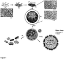
- FIG. 1 An exemplary process according to the present invention is illustrated in Figure 1 .
- the kaolinite particles ( Figure 1A ) are first chemically modified in order to provide them with a functionality suitable for initiation of atom-transfer polymerization. To this end, the particles are treated with (3-aminopropyl) triethoxysilane ( Figure 1B ) to provide free amino groups.
- alkyl bromide groups are immobilized on the free amino groups by treatment of the particles with ⁇ -bromoisobutyryl bromide ( Figure 1C ).
- an emulsion consisting of a solution of a hydrophilic monomer and a solution of a hydrophobic monomer was prepared to which initiator-modified kaolinite particles were added ( Figure 1D ).
- the two solutions should have a difference in surface energy, not be miscible with each other and should thus form a liquid-liquid interface.
- the premodified kaolinite particle should have a surface energy value between the two solutions and therefore localize at the interface between the two solutions. Due to their flattened shape, the kaolinite-based initiator-modified particles adsorb strongly at the liquid-liquid interface. The particle can readily turn around the axis which goes through their flattened sides, while flipping of the particle is hardly possible because considerable energy excess is required.
- the hydrophilic and hydrophobic monomers are then polymerized and immobilized on opposite sides of Janus particles when the polymerization was started in both aqueous and non-aqueous phases.
- the hydrophilic and/or monomers can be chosen according to the desired use of the Janus particles.
- a significant advantage of the process of the present invention is that substantially any monomer may be selected which may be polymerized by ATRP.
- the monomers to be polymerized and immobilized on the opposite sides should be selected such that they have a different solubility in the respective phases forming the liquid-liquid interface.
- Janus particles are amphiphilic colloidal particles that are generally known and described in the literature. Such particles are often referred to as “Janus” particles and may vary in shape, for example, from spherical to egg-like (ellipsoid), "snowman” and dumb-bell (peanut-shaped).
- the term "Janus particles” means an inorganic core particle with a polymer shell wherein the polymeric composition of the polymer shell is different between two different sides of the core particle.
- the particle produced by the present invention has a different polymeric composition on opposite sides of the particle.
- the Janus particles are hybrid Janus particles.
- the core particles for use in the present invention will generally have a height which is smaller than the length scale of the crystals.
- Typical lengths of the core particles are from about 1 to about 50 ⁇ m, preferably from 2 to about 20 ⁇ m.
- Typical heights are about 1 ⁇ m.
- the ratio of the length of a shape to its height is generally referred to as aspect ratio.
- the aspect ratio of the core particles ranges from 1 to 25, preferably from 2 to 15, more preferably from 5 to 10. If core particles having this aspect ratio are used, they absorb strongly at the liquid-liquid interface and flipping of the particle over the interface is hardly possible. Consequently, each side is only decorated with polymerized monomers soluble in the phase that this side is exposed to.
- Preferred core particles have a platelet or disk-like shape. Particles having such a shape are usually of a high aspect ratio.
- the core particles used preferably consist of an inorganic material, more preferably the material of the core particles is kaolinite.
- Kaolinite is a clay formed by alumosilicate particles with flattened disk-like shape and is extremely abundant in nature.
- the particle size of kaolinite for use in the present invention is preferably between 50 nm and 5 ⁇ m, more preferably between 100 nm and 2 ⁇ m.
- Layered-silicate kaolinites have two opposing basal planes, the tetrahedral (TS) and the octahedral (OS) surface.
- Preferred core particles consist mainly of kaolinite since this material is easily available for a low price and has high aspect ratios which are both advantageous features for the use in the present invention.
- the core particles of the desired size are first separated by sedimentation in water for 2 days. Separation may be performed by using grain size separation according to the Atterberg method.
- the conventional Atterberg method is used for separating grain size fractions according to their settling velocity. After the sample was poured into a sedimentation cylinder, deionized water was added up to the desired settling height. The closed cylinder was shaken until the suspension was homogeneous. When the necessary settling time for a given equivalent diameter (e.g., 2 ⁇ m) was reached (calculated according to Stokes law), the supernatant suspension (e.g., only material ⁇ 2 ⁇ m) was decanted and dried.
- equivalent diameter e.g., 2 ⁇ m
- the core particles of a defined size are subsequently purified. This may be done by the EDTA method to remove calcium and magnesium carbonates.
- the kaolinite particles are stirred in an EDTA solution, washed in water and dried.
- deferration of the particles is conducted via the dithionite-citrate-bicarbonate (DCB) method.
- DCB dithionite-citrate-bicarbonate
- kaolinite particles are stirred in a citrate-bicarbonate solution and then heated in a water bath, after which dithionite was added and the solution further incubated. The thus treated particles are collected by centrifugation washed with the citrate-bicarbonate solution and water, and then dried.
- ready-to-use kaolinite particles are modified with an aminating agent to introduce amino groups on the surface of the core particle.
- an aminating agent any aminating agent may suitably be used in the process of the invention.
- aminating agents comprising polylysine or aminoalkylsilanes, such as gamma-aminopropylsilane (GAPS) (e.g., ⁇ -aminopropyl trimethoxysilane, N-(beta- aminoethyl)- ⁇ -aminopropyl trimethoxysilane, N-(beta-aminoethyl)- ⁇ -aminopropyl triethoxysilane or N'-(beta-aminoethyl)- ⁇ -aminopropyl methoxysilane).
- GAPS gamma-aminopropylsilane
- a particularly preferred aminating agent is (3-aminopropyl)triethoxysilane (APS).
- the aminating step may be done by mixing the particles for 7.5% solution of APS in ethanol. The particles are then purified by a centrifugation/redispersion process in ethanol and dried.
- ATRP initiator groups are immobilized on the particle surface.
- alkyl halides are used in the present invention.
- alkyl bromides are used in this step.
- ⁇ -bromoisobutyril bromide is used as alkyl halide.
- ⁇ -bromoisobutyril is preferably immobilized on the particle from its solution in the presence of triethylamine at room temperature under constant stirring for 2 hours.
- Kaolinite particles are then purified by centrifugation/redispersion in dichloromethane, water and ethanol and dried. As a result of this step, premodified core particles having ATRP initiator groups on their surface are obtained.
- a solution A comprising a solvent S1 and a monomer M1 which is soluble in said solvent S1
- a solution B comprising a solvent S2 and a monomer M2 which is soluble in said solvent S2, wherein S1 and S2 are not miscible with each other to form a homogeneous solution, is provided.
- S1 and S2 have a different degree of hydrophilicity. According to another preferred embodiment S1 is more hydrophilic than S2.
- hydrophobic refers to the ability of a chemical compound or moiety to be dissolved / dispersed in or interact with fats, oils, lipids, and non-polar solvents or solvents of moderate polarity, such as hexane or toluene.
- hydrophilic refers to the ability of a chemical compound or moiety to be dissolved / dispersed in or interact with water and other polar substances.
- more hydrophilic refers to an increased hydrophilic character of one chemical compound or mixture of compounds in comparison to another chemical compound or mixture of compounds.
- a chemical compound which is more hydrophilic than a second chemical compound has a higher solubility in water (expressed in g/100g at room temperature) than the second chemical compound.
- any method as known in the art may be employed.
- An example of such a method is performed as follows: a known amount of water - for example, 100g - is put in a container. Then the substance whose solubility is to be determined is added until, even after vigorous and prolonged stirring (i.e. with a 15 mm stir-bar at 120 rpm for 15 minutes at 20°C), some of that substance does not dissolve in the water.
- Such a solution is saturated with the solute once it contains as much dissolved solute as possible at that temperature.
- the amount of dissolved solute corresponds to the solubility of the dissolved substance at the specified temperature in that solvent.
- solubility of liquid solvents in water the amount of the substance exceeding the solubility will form a separate phase to the saturated aqueous solution over time. Examples for the solubility of various solvents in water (expressed in g/100g) are given in Table 1. Table 1.
- the solvent or solvent mixture S1 is water or an aqueous solution, or ionic liquid, in particular S1 is water.
- the solvent or solvent mixture S2 comprises an organic solvent, such as trimethylpentane, ethanol, tetrahydrofurane (THF), pentane, cyclopentane, hexane, cyclohexane, benzene, toluene, anisole or other organic solvents known in the art, in particular anisole.
- organic solvent such as trimethylpentane, ethanol, tetrahydrofurane (THF), pentane, cyclopentane, hexane, cyclohexane, benzene, toluene, anisole or other organic solvents known in the art, in particular anisole.
- the solvent or solvent mixture S1 is immiscible with the solvent or solvent mixture S2 to form a homogeneous solution.
- a solvent or solvent mixture S1 which is immiscible with a solvent or solvent mixture S2 to form a homogeneous solution it is meant that the mixture of the two is not homogeneous after mixing and settle into separate liquid phases or layers of different composition over time.
- the degree of hydrophilicity of substances used in the present invention may also be expressed as the value of surface energy of the respective substance.
- the surface energy of a liquid may be determined by any of the methods as known in the art (see for example David B. Thiessen, et. al.. "Surface Tension Measurement.”Copyright 2000 CRC Press LLC; accessible on http://dsp-book.narod.ru/MISH/CH31.PDF ).
- the surface energy of a liquid as used in the present invention is determined directly by using tensiometry or the pendant drops method.
- S1 and S2 preferably have different values of surface energy, more preferably S1 has a higher surface energy than S2.
- the surface energy of S1 is about 10 mJ/m 2 higher than the surface energy of S2, more preferably the surface energy of S1 is about 20 mJ/m 2 higher than the surface energy of S2, even more preferably the surface energy of S1 is about 30 mJ/m 2 higher than the surface energy of S2.
- the treated core particle should be such that it localizes at the interface of solution A and solution B.
- the value of surface energy of the treated core particle obtained in the step of immobilizing an alkyl halide on the surface of the core particle is between the values of surface energy of solvent S1 and solvent S2. If this requirement is fulfilled, the treated core particle will energetically be driven to localize at the interface between S1 and S2.
- S1 may have a surface energy of about 70 mJ/m 2 , S2 of about 30 mJ/m 2 (determined by direct measurement) and the treated core particle of about 40 mJ/m 2 (calculated from contact angle data).
- soluble means that more than 0.1 g of a substance are soluble in 100 ml of the respective solvent to form a homogeneous solution, preferably more than 0.5 g are soluble, more preferably more than 1 g are soluble therein.
- insoluble means that less than 0.1 g of a substance are soluble in 100 ml of the respective solvent to form a homogeneous solution, preferably less than 0.05 g are soluble, more preferably less than 0.01 g are soluble therein.
- monomer M1 any monomer may be used which is soluble in solvent S1.
- monomer M1 is soluble in solvent S1 and insoluble in solvent S2.
- examples of the monomer M1 which may be used in the present invention are dimethylaminoethyl methacrylate (DMAEMA) or N-isopropylacrylamide (NIPAM).
- DMAEMA dimethylaminoethyl methacrylate
- NIPAM N-isopropylacrylamide
- other water-soluble monomers or monomers soluble in the respective solvent S1 may also be used.
- monomer M2 any monomer may be used which is soluble in solvent S2.
- monomer M2 is soluble in solvent S2 and insoluble in solvent S1.
- examples of the monomer M1 which may be used in the present invention is lauryl methacrylate.
- other water-insoluble monomers or monomers soluble in the respective solvent S2 may also be used.
- an emulsion of solution A and solution B is prepared with the treated core particle having immobilized alkyl halides on the particle surface.
- solution A and solution B are emulsified before the treated core particle is added to the obtained emulsion.
- the treated core particle is introduced into solution A before emulsifying with solution B, alternatively the treated core particle is introduced into solution B before emulsifying with solution A.
- the emulsion obtained from emulsifying solution A and solution B is an oil-in-water emulsion.
- oil-in-water emulsion as used herein means an emulsion in which the more hydrophobic phase is the dispersed liquid and the more hydrophilic phase is the continuous phase.
- the dispersed phase forms small droplets inside the continuous phase.
- the more hydrophilic phase is an aqueous solution and the more hydrophobic phase is an organic solvent, in a preferred embodiment the aqueous solution is water, in another preferred embodiment the organic solvent is anisole.
- the solutions may be mixed by a screw mixer, high-shear mixer, disperser or other mixing equipment suitable for the mixing step.
- One example for the mixing step is mixing in an Ultra-Turax mixer (IKA Laboratory Equipment, Staufen, Germany) at 13500 rpm for 2 minutes.
- the process of the present invention further comprises a step of initiating the polymerization of monomer M1 at the surface of the core particle facing solvent S1 and of monomer M2 at the surface of the core particle facing solvent S2.
- the polymerization of the monomers on the separate surfaces of the core particle facing the respective solvents is preferably initiated concomitantly.
- the step of initiating the polymerization of monomer M1 and initiating the polymerization of monomer M2 takes place in the same emulsion.
- the polymerization of the monomers occurs by radical polymerization, in particular the polymerization occurs by Atom Transfer Radical Polymerization (ATRP).
- ATRP is a technique which is commonly known in the art and its details are readily apparent to the skilled person. Further information may be taken, inter alia, from “ Controlled/Living Radical Polymerization: Progress in ATRP", Krzysztof Matyjaszewski, 2009, Oxford Univ Pr, ISBN: 978-0841269958 .
- any initiator may be used which is able to initiate the polymerization reaction and is soluble in solvent S1, preferably ⁇ -bromoisobutyric acid is used as an initiator in bulk.
- any initiator may be used which is able to initiate the polymerization reaction and is soluble in solvent S2, preferably ethyl ⁇ -bromoisobutyrate is used as an initiator in bulk.
- the mixture containing the solvent S1, the monomer M1, the initiator and optionally a catalyst and a reducing agent and the mixture containing the solvent S2, the monomer M2, the initiator and optionally a catalyst and a reducing agent are prepared separately and mixed with the treated core particle to initiate the polymerization of the monomers on the respective surfaces of the treated core particle.
- the polymerization is preferably conducted for 1 to 3 hours, preferably while stirring at a speed of 1100 to 1400 rpm.
- the polymerization reaction is conducted at a temperature of 60 to 80°C.
- the process of the present invention further comprises a step of separating the Janus particles.
- the separation is conducted after the polymerization reaction has terminated.
- the polymerization reaction has terminated when more than 90% of the monomer have been polymerized.
- the Janus particles are collected by centrifugation and may be washed in different solvents (DMF, toluene, ethanol, water). Any suitable separation method may be used to separate the Janus particles of the present invention from the polymerization solution/polymerization emulsion.
- solvents DMF, toluene, ethanol, water.
- the present invention provides Janus particles obtainable by the process of the present invention.
- the present invention further provides Janus particles with a polymer shell wherein one surface of the particle is covered with a different polymer than the other surface.
- the grafted polymers on at least one surface of the particle form polymer brush structures, in particular the grafted polymers on both surfaces form polymer brush structures.
- Polymer chains are able to form so-called brush structures if they are grafted to a surface with a high grafting density, i.e. if the distance between the grafted polymer chains (grafting points) is lower than the radius of gyration (Rg) of grafted polymer coils in ⁇ conditions (R g ⁇ ⁇ 5 nm; Iyer, K. S. et al., Macromolecules 2003, 36, 6519-6526 and lonov, L. et al., Langmuir 2005, 21, 8711-8716 ).
- the grafted polymers are considered to form brush structures if they have a grafting density of 0.1 chains/nm 2 or more.
- the average of the grafting densities of polymers on the two surfaces of the core particle is greater than 0.05 chains/nm 2 , in particular greater than 0.1 chains/nm 2 .
- the grafting density of the polymers on one of the surfaces of the core particle is greater than 0.05 chains/nm 2 , in particular greater than 0.1 chains/nm 2 .
- the grafting density of the polymers on each of the surfaces of the core particle particle is greater than 0.05 chains/nm 2 , in particular greater than 0.1 chains/nm 2 .
- This invention further provides but does not claim the use of the Janus particles for coatings with self-healing, anti-soiling, anti-fouling, anti-fogging and/or anti-icing properties, in particular for coatings having anti-icing properties.
- the synthesized Janus particle can be successfully applied for the design of coatings with anti-ice properties.
- adhesion of the ice to hydrophobic surfaces (such as PDMS or PLMA polymers) and to surfaces made of Janus particles (covered with PEGMA/PDMS and PDMAEMA/PLMA) is comparable to each other and clearly lower (about 3 times) than adhesion of ice to hydrophilic surfaces (such as PEGMA or PDMAEMA polymers).
- surfaces made of amphiphilic (hydrophobic/hydrophilic) Janus particles combine low freezing points of hydrophilic polymeric surfaces and low ice adhesion intrinsic to hydrophobic surfaces.
- This invention further provides the use of Atom Transfer Radical Polymerization (ATRP) for the preparation of Janus particles.
- ATRP Atom Transfer Radical Polymerization
- the invention also defines that ATRP of different monomers occurs in the same emulsion at different surfaces of a particle.
- an aspect is provided but does not claim the use of an oil/water emulsion for the simultaneous covering of two surfaces of a particle with different polymers.
- the oil/water emulsion is an oil-in-water emulsion.
- the value of surface energy of the particle is between the values of surface energy of the different phases of the emulsion.
- the degree of hydrophilicity of the particle is between the degree of hydrophilicity of the different phases of the emulsion.
- Ethanol abs. (EtOH, VWR, 99.9%), 3-aminopropyltriethoxysilane (APS, ABCR, 97%), ⁇ -bromoisobutyryl bromide (Aldrich, 98%), ⁇ -bromoisobutyric acid (BiBA, Aldrich, 98%), anhydrous dichloromethane (Fluka), triethylamine (Fluka), copper(II) bromide (Aldrich, 99.999%), tin(II) 2-ethylhexanoate (Aldrich, 95%), tris(2-pyridylmethyl)amine (TPMA, Aldrich, 98%), N,N,N',N",N"-Pentamethyldiethylenetriamine (PMDTA, Aldrich, 99%), N,N- dimethylformamide (DMF, Aldrich, 99.8%), ethyl ⁇
- Methyl methacrylate (Aldrich) and styrene (Aldrich) were passed through acidic, neutral and basic aluminium oxides prior to the polymerization.
- tri(n-butyl)tin hydride (97%, Aldrich) and tetrahydrofurane (99.9%, Aldrich) were used as received.
- Lauryl methacrylate (LMA, Aldrich), 2-(dimethylamino)ethyl methacrylate (DMAEMA, Aldrich) and oligo(ethylene glycol) methyl ether methacrylate (OEGMA, Aldrich) were filtered prior to the polymerization through acidic, neutral and basic aluminium oxides respectively. Millipore water was obtained from Milli-Q (Millipore). Conductivity: 0.055 ⁇ S/cm.
- SEM Scanning Electron Microscopy
- SEM scanning electron microscopy
- SE secondary electron
- samples were coated with platinum (3.5 nm) using a Leica EM SCD500 sputter coater.
- Transmission Electron Microscopy (TEM) and Cryo-TEM Transmission Electron Microscopy (TEM) images and cryogenic TEM images were taken with a Libra 120 cryo-TEM from Carl Zeiss NTS GmbH equipped with a LaB6 source. The acceleration voltage was 120kV and the energy filter with an energy window of 15 eV was used.
- the kaolinite JP sample for cryo-TEM was prepared as follows. First, PDMAEMA was stained (quaternized) with CH 3 I to enhance the contrast in TEM. Then the JPs were dispersed in water (0.5 mg/ml) by ultrasonication for 20 minutes and left to settle overnight. Prior to the analysis 3.5 ⁇ l of the sample were taken from the upper part, blotted and vitrified in liquid ethane at -178°C. Ultimately, an approx. 200 nm thick ice film was examined in the TEM. Lamellas for TEM investigations were cut from kaolinite samples with a Focused Ion Beam (FIB).
- FIB Focused Ion Beam
- AFM Atomic Force Microscopy
- the wafer was annealed for 20 minutes at 150°C in a vacuum oven in order to chemically graft PGMA.
- the obtained PGMA layer thickness was 7 nm.
- a dispersion of kaolinite JPs was prepared in ethanol (1mg/ml) and a few drops were deposited onto a PGMA-coated wafer.
- the wafer was again annealed at 150°C for two hours in a vacuum oven. Multilayers were then removed by ultrasonication.
- AFM measurements under water Atomic force microscopy images were taken with a Bruker Dimension® IconTM AFM (Bruker, USA). Contact mode in fluid was used to capture force-distance curves from kaolinite samples.
- Bruker's Dimension® IconTM is equipped with ScanAsystTM automatic image optimization technology, which enables easier, faster, and more consistent results.
- the ScanAsystTM option was used for topographical measurements with a Si 3 N 4 cantilever with a spring constant of 0.7 N/m.
- For force-distance measurements a Si 3 N 4 cantilever with a spring constant of 0.02 N/m was used.
- the "Point & Shoot" option was utilized for kaolinite samples to accurately trigger force measurements at desired locations.
- Electrolyte solutions have been prepared from 0.1 molar KCI, using 0.1 molar HCI and KOH to adjust the pH value. Thus, measurements were carried out at pH 2, 6 and 10 in DI water and at the same pH values in 10 -3 and 10 -1 molar KCI.
- the wafer was rinsed with DI water or the electrolyte solution by placing a certain amount of it (approx. 0.5-1 ml) between the sample and the probe holder with a syringe, then removing it with a tissue and placing another portion of the solution (or water). The procedure was repeated at least 3 times and then the sample was left to equilibrate in the solution for 20 minutes. In all measurements, AFM probes were first brought into contact with the substrate. When the AFM cantilever was withdrawn from the contact, the force was measured between the probe and the sample.
- Electrokinetic measurements The pH-dependent electrokinetic measurements (via electrophoresis) of the particles in dispersion were carried out with a Zetasizer Nano ZS from Malvern Instruments Ltd. and an MPT-2 autotitrator. For all measurements, the particles were suspended in a solution of 10 -3 M KCI in water (10 mg/24 ml or 0.42 mg/ml). The pH of the prepared suspensions was controlled by adding 0.1 M KOH or HCl aqueous solutions. Three measurements were recorded for each sample at each pH value.
- Thermogravimetric Analysis (TGA). Thermogravimetric analysis (TGA) measurements have been conducted on a TGA Q 5000IR device from TA Instruments Co. The chosen measurement conditions were a temperature span up to 800°C and measurement under air.
- FTIR-ATR Spectroscopy FTIR-ATR Spectroscopy. FTIR-ATR spectra were taken with an IFS 55 (Bruker, Germany) spectrometer for all prepared systems. Moreover, FTIR-ATR spectroscopy was used for determination of grafted amount of polymer. Details of the calibration procedure are given elsewhere ( Berger, S., et al., 2008. Macromolecules 41, 9669-9676 ). Briefly, the grafted amount was estimated using calibration curves plotted from the absorbency spectra of the samples, made from a mixture of the polymer and particles (50 mg).
- FTIR spectra of Janus particles contain characteristic bands of both polymers (for instance): PDMAEMA (at 2850 cm-1) and PLMA (at 2770 cm-1) that is the direct evidence for successful grafting of both polymers.
- PDMAEMA at 2850 cm-1
- PLMA at 2770 cm-1
- Optical Microscopy Optical microscopy images were taken with an Olympus BX51 microscope equipped with an Olympus UC30 camera and recorded with an analySIS docu software (Olympus Soft Imaging Solutions GmBH).
- Kaolinite particles (Fluka) were used as received without further purification. They were separated by sedimentation in DI water for 2 days. 100 nm - 2 ⁇ m large particles are separated using grain size separation (Atterberg method). To estimate the sand (>63 ⁇ m), silt (2-63 ⁇ m), and clay ( ⁇ 2 ⁇ m) fraction in the cuttings, these fractions were separated by sieving and settling methods (Atterberg method).
- the conventional Atterberg method is used for separating grain size fractions according to their settling velocity. After the sample was poured into a sedimentation cylinder, deionized water was added up to the desired settling height. The closed cylinder was shaken until the suspension was homogeneous. When the necessary settling time for a given equivalent diameter (e.g., 2 ⁇ m) was reached (calculated according to Stokes law), the supernatant suspension (e.g., only material ⁇ 2 ⁇ m) was decanted and dried.
- equivalent diameter e.g. 2 ⁇ m
- Kaolinite was purified after separation by the EDTA method to remove calcium and magnesium carbonates. Briefly, a certain amount of kaolinite particles was stirred in a 0.1 molar EDTA solution for 2 hours, then collected by centrifugation, washed in water several times via centrifugation/redispersion and dried under vacuum at 60°C. Deferration was conducted via the dithionite-citrate-bicarbonate (DCB) method. In short, a certain amount of kaolinite particles purified by the EDTA method was stirred in a citrate-bicarbonate solution and then heated in a water bath at 75°C, after which dithionite was added in two portions. The mixture was allowed to stir for 10 more minutes and the particles were then collected by centrifugation. Further, the collected particles were washed 3 times in the citrate-bicarbonate solution and 3 times in water, and then dried under vacuum at 60°C.
- DCB dithionite-citrate-bicarbonate
- Purified and dried kaolinite particles were then modified with (3-aminopropyl)triethoxysilane (APS) to introduce amino groups onto the surface. This was done by mixing the particles for 12 hours in a 7.5% solution of APS in ethanol. The particles were then purified by a centrifugation/redispersion process in ethanol for 6 times and dried in vacuum at 60 °C.
- APS (3-aminopropyl)triethoxysilane
- the ATRP initiator (a-bromoisobutyril bromide) is immobilized on the particle surface from its solution in dry dichloromethane (0.7 ml Brln in 35 ml DCM) in the presence of triethylamine (1.4 ml). The reaction is carried out at room temperature under constant stirring for 2 hours. Kaolinite particles are then purified by centrifugation/redispersion in DCM, water and ethanol and dried under vacuum.
- a water-soluble monomer for instance DMAEMA, NIPAM or OEGMA
- DMAEMA dimethyl methacrylate
- NIPAM dimethyl methacrylate
- PMDTA N,N,N',N',N"-Pentamethyldiethylenetriamine
- a 2-neck round-bottom flask with initiator-modified kaolinite and the water-soluble ATRP mixture is put in a water bath heated to 70-80°C and continuously purged with Ar during the whole polymerization process.
- the oil phase ATRP mixture consists of lauryl methacrylate as a water-insoluble monomer, anisole as a solvent, copper (II) bromide and tris(2-pyridylmethyl)amine (TPMA) as a catalyst, ethyl ⁇ -bromoisobutyrate (EBiB) as an initiator in bulk and tin 2-ethylhexanoate as a reducing agent.
- This mixture is introduced to the water phase and mixing by a mechanical stirrer is started.
- the simultaneous ATRPs are conducted for 1-3 hours at 1100-1400 rpm mixing speed. After polymerization the obtained bi-component amphiphilic kaolinite Janus particles are collected by centrifugation and washed in different solvents (DMF, toluene, ethanol, water).
- Mono-component kaolinite Janus particles with PDMAEMA and PLMA shells were prepared as described above, the only difference being the absence of one of the monomers.
- pure anisole was taken as an oil phase, and for the synthesis of PLMA/Br JPs pure water as a water phase.
- Kaolinite-based Janus particles with two polymers which have a similar polarity (such as PMMA and PS) were synthesized as follows. First, mono-component Janus particles with PMMA were prepared using the same procedure as for the PLMA/Br mono-component JPs. The acquired particles were washed 8 times in different solvents (toluene, chloroform, THF) and dried under reduced pressure.
- a dehalogenation step was then conducted to remove bromine from the grafted particles.
- PMMA/Br JPs 350 mg were dispersed in 25 ml of anisole by ultrasonication, followed by the addition of 40 ⁇ l of PMDTA and 23 ⁇ l of EBiB. The mixture was purged with Ar for 40 minutes.
- the mixture was degassed by freeze-pump-backfilling with N 2 three times. 34 mg CuBr were added via septum and the freeze-pump-backfilling cycle was repeated one more time.
- the test tube was transferred to an oil bath heated to 100°C and 200 ⁇ l of tri(n-butyl)tin hydride were injected into the mixture with a syringe. The mixture was stirred overnight in the oil bath at 600 rpm. The particles were then collected by centrifugation and washed with anisole and toluene.
- the ATRP-initiator was immobilized onto the uncovered side of the particles using the procedure described above.
- the second polymer (PS) was then grafted from the initiator-modified side of the kaolinite particles.
- Fully-covered kaolinite particles were synthesized by using the kaolinite particles modified with the ATRP-initiator and performing the ATRP in a similar way as described for the grafting of PS.
- PDMAEMA and PLMA were taken as monomers for this purpose and, as a result, kaolinite particles fully-covered with PDMAEMA and fully-covered with PLMA were prepared.
- the molecular weight of polymer obtained in solution is comparable to that of grafted polymer chains.
- the amount of grafted polymer was determined by TGA to be 20 wt. %.
- the estimated value of grafting density was ca. 0.11 chains/nm 2 which is comparable to the previously reported value of grafting density obtained using AGRET-ATRP on SiO 2 substrate.
- ⁇ chains / nm 2 f pol 1 ⁇ f pol N A M n S BET
- paraffin droplets have a spherical shape after cooling to room temperature and crystallization.
- the surface of obtained paraffin (wax) droplets are fully covered by flattened kaolinite particles (see magnifications of step D, upper right corner of Figure 1 ). This behavior can fully be explained by considering the surface tension of water, oil and Br-modified particles which are 72 mJ/m 2 , 28 mJ/m 2 and 40 mJ/m 2 .
- the surface tension of Br-modified particles is between values of surface tension of liquids and their segregation between liquids is energetically favorable.
- thermogravimetric analysis and streaming potential measurements were conducted for mono-competent particles (for comparison) and the inventive particles as described above.
- IEP isoelectric point
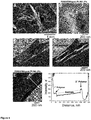
- the polymer-modified particles have a smoother shape ( Figure 4A ) than native ones because of the polymer shell.
- a shell of swollen PDMAEMA in water can also be seen around the PDMAEMA/PLMA Janus particles by using cryo-EM ( Figure 4B ).
- each layer was found to be in the range of ca 30 nm, i.e. comparable to the results of TGA and FTIR. Thus, based on scanning and transmission electron microscopy observation, we can conclude that grafting of polymers to both sides of the kaolinite particles was successful.
- PLMA is hydrophobic and uncharged.
- PDMAEMA is hydrophilic and positively charged.
- PAA is hydrophilic and negatively charged. PAA particles are strongly electrostatically stabilized and do not adsorb on any hydrophobic as well as hydrophilic uncharged or negative charged surface.
- PAA particles are strongly adsorbed on positively charged PDMAEMA surface due to electrostatic attraction. Therefore, the character of adsorption of PAA particles can be considered as an indication of the grafted polymer: PDMAEMA sides of Janus particles are covered by PAA particles, while PLMA ones are bald ( Figure 5a, b ).
- the grafted polymers PLMA and PDMAEMA have different adhesive properties.
- PDMAEMA is non-adhesive ( Figure 6A )
- PLMA is strongly adhesive ( Figure 6B ).
- a PGMA film was spincoated from a 2% THF solution at 2000 rpm on a Si wafer to a thickness of the resulting PGMA layer of 80 nm.
- the PGMA film was annealed at 150°C for 2h.
- Polymer-modified kaolinite Janus particles ware deposited on the PGMA surface by drying their ethanol dispersion (2 mass %)
- the adhesion measurements under water revealed different adhesion properties of Janus-particles layers ( Figure 6 ).
- the synthesized hairy Janus particles can be further used for the fabrication of materials with controlled adhesion properties and especially anti-fouling materials.
- composite layers with controlled adhesive/non-adhesive behavior could be designed.
- a composite blend was prepared from the suspension of PS and PMMA with a ratio of 30:70 in THF solution (1:10) and 5 wt% of polymer-kaolinite Janus particles.
- the suspension was mixed during 15 min at 13500 rpm using Ultra-Turax.
- ca. 4 mm thick films were prepared by casting technique. Solvent was evaporated during 24 h in vacuum oven at 70°C.
- the final film thickness of prepared composite blend was measured to be 400 ⁇ m.
- the obtained thick film was investigated using SEM (images are shown in Figure 8 ).
- the lamellas for TEM investigations were cut from composite kaolinite samples with a Focused Ion Beam (FIB).
- the film thickness for TEM investigations was 150 nm.
- Particles are seen as bright dots around circles in SEM mages and as dark lines in TEM images. The observations show that particles segregate at the interface between the polymers that, as expected, must provide better compatibilization of blends and must reinforce them.
- inventive Janus particles may also be used for the stabilization of polymer blends.
- the inventive Janus particle can be successfully applied for the design of coatings with anti-ice properties.
- electrokinetic as well as wetting properties of the obtained layers were studied.
- the reference surfaces made of one sort of polymer on fully covered particles were investigated.
- the prepared coatings consisting of fully covered (as reference sample) and Janus particles were characterized by streaming potential measurements ( Fig. 8 ).
- the contact angle measurements revealed the chemical heterogeneity of the coatings.
- the advancing contact angle measured on the coating made of Janus particles is in between the contact angles measured with surfaces of fully covered particles.
- the receding contact angle measured on the coating made of Janus particles is higher than the angles measured for the fully covered particles (Table 1).
- Table 1 Summary of wetting behavior measured on coatings formed of fully covered (FC) PDMAEMA and PLMA as well as Janus (PDMAEMA/PLMA) particles.
- the experiments were performed in a chamber under controlled temperature and humidity levels (under 80% of relative humidity and temperature range from +20°C to - 20°C, cooling rate 0.5°C).
- adhesion of ice to hydrophobic surfaces (PDMS or PLMA) and surfaces made of Janus particles (PEGMA-PDMS and PDMAEMA-PLMA) is similar and clearly lower (about 3 times) then adhesion of the ice to hydrophilic surfaces (PEGMA, PDMAEMA).
Landscapes
- Chemical & Material Sciences (AREA)
- Organic Chemistry (AREA)
- Dispersion Chemistry (AREA)
- Chemical Kinetics & Catalysis (AREA)
- Polymerisation Methods In General (AREA)
- Graft Or Block Polymers (AREA)
Claims (9)
- Verfahren zur Herstellung von Janus-Teilchen, umfassend die folgenden Schritte:a) Behandeln eines Kernteilchens mit einem aminierenden Mittel, wobei Aminogruppen auf der Oberfläche des Kernteilchens eingebracht werden,b) Immobilisieren eines Alkylhalogenids auf der Oberfläche des Kernteilchens,c) Bereitstellen einer Lösung A, umfassend ein Lösungsmittel S1 und ein Monomer M1, welches in dem Lösungsmittel S1 löslich ist,
und einer Lösung B, umfassend ein Lösungsmittel S2 und ein Monomer M2, welches in dem Lösungsmittel S2 löslich ist,
wobei S1 und S2 nicht miteinander mischbar sind, um eine homogene Lösung zu bilden,d) Herstellen einer Emulsion von Lösung A und Lösung B mit dem behandelten von Schritt b) erhaltenen Kernteilchen,e) Initiieren der Polymerisation von Monomer M1 an der Oberfläche des Kernteilchens, welche Lösungsmittel S1 zugewandt ist, und von Monomer M2 an der Oberfläche des Kernteilchens, welche Lösungsmittel S2 zugewandt ist, wobei Polymerisation der Monomere durch Atomübertragungsradikalpolymerisation (ATRP) auftritt, undf) Abtrennen der Janus-Teilchen. - Verfahren gemäß Anspruch 1, wobei das behandelte Kernteilchen, welches zu der Emulsion in Schritt d) gegeben wird, an der Grenzfläche von Lösung A und Lösung B lokalisiert ist, bevor Schritt e) durchgeführt wird.
- Verfahren gemäß Anspruch 1 oder 2, wobei das Kernmaterial eine plättchen- oder scheibenförmige Form aufweist und/oder wobei das Kernmaterial ein anorganisches Material ist, wobei das Kernmaterial bevorzugt Kaolinit ist.
- Verfahren gemäß einem der vorhergehenden Ansprüche, wobei der Wert der Oberflächenenergie des behandelten in Schritt b) erhaltenen Kernteilchens zwischen den Werten für die Oberflächenenergie von Lösungsmittel S1 und S2 liegt und/oder wobei S1 und S2 ein unterschiedliches Ausmaß von Hydrophilie aufweisen, wobei insbesondere S1 stärker hydrophil als S2 ist.
- Verfahren gemäß einem der vorhergehenden Ansprüche, wobei S1 ein wässriges Lösungsmittel ist, wobei insbesondere S1 Wasser ist, und/oder wobei S2 ein organisches Lösungsmittel ist, wobei insbesondere S2 Anisol ist.
- Verfahren gemäß einem der vorhergehenden Ansprüche, wobei die Hydrophilie des behandelten in Schritt b) erhaltenen Kernteilchens zwischen dem Ausmaß von Hydrophilie von S1 und dem Ausmaß von Hydrophilie von S2 liegt.
- Verfahren gemäß einem der vorhergehenden Ansprüche, wobei die in Schritt d) erhaltene Emulsion eine Öl-in-Wasser-Emulsion ist.
- Verfahren gemäß einem der vorhergehenden Ansprüche, wobei Initiieren der Polymerisation von Monomer M1 und Initiieren der Polymerisation von Monomer M2 in derselben Emulsion stattfindet.
- Verwendung von Atomübertragungsradikalpolymerisation (ATRP) für die Herstellung von Janus-Teilchen, wobei die Atomübertragungsradikalpolymerisation (ATRP) von unterschiedlichen Monomeren in derselben Emulsion an unterschiedlichen Oberflächen eines Teilchens auftritt.
Priority Applications (5)
| Application Number | Priority Date | Filing Date | Title |
|---|---|---|---|
| EP14153410.7A EP2902103B1 (de) | 2014-01-31 | 2014-01-31 | Verfahren zum herstellen von janusteilchen mit polymerschalen |
| PT141534107T PT2902103T (pt) | 2014-01-31 | 2014-01-31 | Um processo para preparar partículas janus com invólucros poliméricos |
| ES14153410T ES2748118T3 (es) | 2014-01-31 | 2014-01-31 | Proceso para preparar partículas de Janus con cubiertas poliméricas |
| PL14153410T PL2902103T3 (pl) | 2014-01-31 | 2014-01-31 | Sposób wytwarzania cząstek Janusa z otoczkami polimerowymi |
| HK15111087.4A HK1210090B (en) | 2015-11-11 | A process to prepare janus particles with polymer shells |
Applications Claiming Priority (1)
| Application Number | Priority Date | Filing Date | Title |
|---|---|---|---|
| EP14153410.7A EP2902103B1 (de) | 2014-01-31 | 2014-01-31 | Verfahren zum herstellen von janusteilchen mit polymerschalen |
Publications (2)
| Publication Number | Publication Date |
|---|---|
| EP2902103A1 EP2902103A1 (de) | 2015-08-05 |
| EP2902103B1 true EP2902103B1 (de) | 2019-07-03 |
Family
ID=50030108
Family Applications (1)
| Application Number | Title | Priority Date | Filing Date |
|---|---|---|---|
| EP14153410.7A Active EP2902103B1 (de) | 2014-01-31 | 2014-01-31 | Verfahren zum herstellen von janusteilchen mit polymerschalen |
Country Status (4)
| Country | Link |
|---|---|
| EP (1) | EP2902103B1 (de) |
| ES (1) | ES2748118T3 (de) |
| PL (1) | PL2902103T3 (de) |
| PT (1) | PT2902103T (de) |
Families Citing this family (12)
| Publication number | Priority date | Publication date | Assignee | Title |
|---|---|---|---|---|
| CN105440218B (zh) * | 2014-08-22 | 2018-11-30 | 中国科学院化学研究所 | 有机/无机杂化Janus颗粒的可控批量制备方法 |
| RU2659254C2 (ru) * | 2016-12-19 | 2018-06-29 | Федеральное государственное бюджетное образовательное учреждение высшего образования "Московский государственный университет имени М.В. Ломоносова" (МГУ) | Способ получения янусовских неорганических частиц |
| CN107930544B (zh) * | 2017-11-27 | 2019-12-13 | 陕西师范大学 | 磁响应性负载型Janus多级孔SiO2复合微球及其制备方法 |
| CN108671859B (zh) * | 2018-06-08 | 2020-10-13 | 陕西师范大学 | 基于溶菌酶纳米薄膜制备Janus颗粒的方法 |
| IT201800006709A1 (it) * | 2018-06-27 | 2019-12-27 | Metodo di fabbricazione di particelle Giano e loro applicazione cosmetica. | |
| CN108855214B (zh) * | 2018-06-29 | 2021-01-29 | 深圳大学 | 金属催化剂及其制备方法 |
| CN113694824B (zh) * | 2020-05-20 | 2023-04-07 | 中国石油天然气股份有限公司 | 一种双面异性纳米片及其制备方法 |
| CN114057961B (zh) * | 2020-07-29 | 2022-11-18 | 清华大学 | 一种聚合物双链/无机纳米颗粒复合Janus材料及其制备方法 |
| CN112892430B (zh) * | 2021-01-15 | 2022-08-23 | 江苏大学 | 一种Pickering乳液构建封装离子液体萃取材料的方法及其应用 |
| CN113731491B (zh) * | 2021-10-15 | 2023-11-10 | 辽宁大学 | 一种基于雪人形Janus复合粒子为载体的仿酶催化剂的制备方法和应用 |
| CN114014370B (zh) * | 2021-11-05 | 2023-06-23 | 珠海复旦创新研究院 | 一种多重响应性Janus四氧化三铁纳米颗粒及其制备方法 |
| CN114058353B (zh) * | 2021-12-02 | 2022-08-09 | 中国石油大学(北京) | 一种Janus改性二硫化钼纳米颗粒及其制备方法与驱油材料 |
Family Cites Families (4)
| Publication number | Priority date | Publication date | Assignee | Title |
|---|---|---|---|---|
| CN102211753A (zh) * | 2010-04-08 | 2011-10-12 | 中国科学院化学研究所 | 表面具有多重性质的复合材料及其制备方法 |
| CN102653580B (zh) * | 2011-03-01 | 2016-02-17 | 河北工业大学 | 一种Janus结构复合乳胶粒子的制备方法 |
| CN102304204B (zh) * | 2011-05-20 | 2014-09-10 | 中科院广州化学有限公司 | 一种含氟双功能性微球及其应用 |
| GB201117304D0 (en) * | 2011-10-07 | 2011-11-16 | Univ Warwick | Use |
-
2014
- 2014-01-31 PT PT141534107T patent/PT2902103T/pt unknown
- 2014-01-31 ES ES14153410T patent/ES2748118T3/es active Active
- 2014-01-31 PL PL14153410T patent/PL2902103T3/pl unknown
- 2014-01-31 EP EP14153410.7A patent/EP2902103B1/de active Active
Non-Patent Citations (1)
| Title |
|---|
| None * |
Also Published As
| Publication number | Publication date |
|---|---|
| ES2748118T3 (es) | 2020-03-13 |
| HK1210090A1 (en) | 2016-04-15 |
| PT2902103T (pt) | 2019-10-18 |
| EP2902103A1 (de) | 2015-08-05 |
| PL2902103T3 (pl) | 2020-01-31 |
Similar Documents
| Publication | Publication Date | Title |
|---|---|---|
| EP2902103A1 (de) | Janusteilchen mit Polymerschalen | |
| Kirillova et al. | Platelet Janus particles with hairy polymer shells for multifunctional materials | |
| US10874991B2 (en) | Functional filters for hydrophobic liquid/hydrophilic liquid separations | |
| Zhou et al. | Cellulose nanocrystals/fluorinated polyacrylate soap-free emulsion prepared via RAFT-assisted Pickering emulsion polymerization | |
| Zgheib et al. | Cerium oxide encapsulation by emulsion polymerization using hydrophilic macroRAFT agents | |
| Qiao et al. | Nitroxide-mediated polymerization-induced self-assembly of block copolymers at the surface of silica particles: toward new hybrid morphologies | |
| US20200263025A1 (en) | A Core-Shell Nanoparticle | |
| Czarnecki et al. | Hybrid Silicon‐Based Organic/Inorganic Block Copolymers with Sol–Gel Active Moieties: Synthetic Advances, Self‐Assembly and Applications in Biomedicine and Materials Science | |
| Bourgeat-Lami et al. | Nucleation of polystyrene latex particles in the presence of γ-methacryloxypropyltrimethoxysilane: Functionalized silica particles | |
| EP2288449B1 (de) | Hybridteilchen im nanobereich | |
| Ruhland et al. | Nanoscale hybrid silica/polymer Janus particles with a double-responsive hemicorona | |
| Nasiri et al. | Stimuli-responsive behavior of smart copolymers-grafted magnetic nanoparticles: Effect of sequence of copolymer blocks | |
| Silva et al. | Investigation of the adsorption of amphipathic macroraft agents onto montmorillonite clay | |
| van Wijk et al. | Formation of hybrid poly (styrene-co-maleic anhydride)–silica microcapsules | |
| Zhao et al. | One-pot formation of monodisperse polymer@ SiO2 core–shell nanoparticles via surfactant-free emulsion polymerization using an adaptive silica precursor polymer | |
| CN105777998A (zh) | 锥形Janus颗粒、制备方法与其应用 | |
| Sun et al. | The effect of steric repulsion between highly branched hydrophilic blocks on inverse cubic mesophase formation in block copolymers | |
| Yang et al. | Novel associative nanoparticles grafted with hydrophobically modified zwitterionic polymer brushes for the rheological control of aqueous polymer gel fluids | |
| HK1210090B (en) | A process to prepare janus particles with polymer shells | |
| Li et al. | What is the role of PEO chains in the assembly of core-corona supraparticles in aqueous dispersions? | |
| Nehache et al. | Self-assembly of PS-PNaSS-PS triblock copolymers from solution to the solid state | |
| Zhao et al. | Reversible addition-fragmentation chain transfer polymerization from surfaces | |
| Kirillova et al. | Programmed assembly of oppositely charged homogeneously decorated and Janus particles | |
| Fujii et al. | Surface characterization of nanoparticles carrying pH-responsive polymer hair | |
| Bourgeat-Lami | Hybrid organic/inorganic particles |
Legal Events
| Date | Code | Title | Description |
|---|---|---|---|
| PUAI | Public reference made under article 153(3) epc to a published international application that has entered the european phase |
Free format text: ORIGINAL CODE: 0009012 |
|
| 17P | Request for examination filed |
Effective date: 20140131 |
|
| AK | Designated contracting states |
Kind code of ref document: A1 Designated state(s): AL AT BE BG CH CY CZ DE DK EE ES FI FR GB GR HR HU IE IS IT LI LT LU LV MC MK MT NL NO PL PT RO RS SE SI SK SM TR |
|
| AX | Request for extension of the european patent |
Extension state: BA ME |
|
| 17P | Request for examination filed |
Effective date: 20160204 |
|
| RBV | Designated contracting states (corrected) |
Designated state(s): AL AT BE BG CH CY CZ DE DK EE ES FI FR GB GR HR HU IE IS IT LI LT LU LV MC MK MT NL NO PL PT RO RS SE SI SK SM TR |
|
| REG | Reference to a national code |
Ref country code: HK Ref legal event code: DE Ref document number: 1210090 Country of ref document: HK |
|
| STAA | Information on the status of an ep patent application or granted ep patent |
Free format text: STATUS: EXAMINATION IS IN PROGRESS |
|
| 17Q | First examination report despatched |
Effective date: 20161220 |
|
| GRAP | Despatch of communication of intention to grant a patent |
Free format text: ORIGINAL CODE: EPIDOSNIGR1 |
|
| STAA | Information on the status of an ep patent application or granted ep patent |
Free format text: STATUS: GRANT OF PATENT IS INTENDED |
|
| INTG | Intention to grant announced |
Effective date: 20190206 |
|
| GRAS | Grant fee paid |
Free format text: ORIGINAL CODE: EPIDOSNIGR3 |
|
| GRAA | (expected) grant |
Free format text: ORIGINAL CODE: 0009210 |
|
| STAA | Information on the status of an ep patent application or granted ep patent |
Free format text: STATUS: THE PATENT HAS BEEN GRANTED |
|
| AK | Designated contracting states |
Kind code of ref document: B1 Designated state(s): AL AT BE BG CH CY CZ DE DK EE ES FI FR GB GR HR HU IE IS IT LI LT LU LV MC MK MT NL NO PL PT RO RS SE SI SK SM TR |
|
| REG | Reference to a national code |
Ref country code: GB Ref legal event code: FG4D |
|
| REG | Reference to a national code |
Ref country code: CH Ref legal event code: EP Ref country code: AT Ref legal event code: REF Ref document number: 1150301 Country of ref document: AT Kind code of ref document: T Effective date: 20190715 |
|
| REG | Reference to a national code |
Ref country code: IE Ref legal event code: FG4D |
|
| REG | Reference to a national code |
Ref country code: DE Ref legal event code: R096 Ref document number: 602014049339 Country of ref document: DE |
|
| REG | Reference to a national code |
Ref country code: CH Ref legal event code: NV Representative=s name: VALIPAT S.A. C/O BOVARD SA NEUCHATEL, CH Ref country code: SE Ref legal event code: TRGR |
|
| REG | Reference to a national code |
Ref country code: PT Ref legal event code: SC4A Ref document number: 2902103 Country of ref document: PT Date of ref document: 20191018 Kind code of ref document: T Free format text: AVAILABILITY OF NATIONAL TRANSLATION Effective date: 20190927 |
|
| REG | Reference to a national code |
Ref country code: NL Ref legal event code: FP |
|
| REG | Reference to a national code |
Ref country code: LT Ref legal event code: MG4D |
|
| PG25 | Lapsed in a contracting state [announced via postgrant information from national office to epo] |
Ref country code: LT Free format text: LAPSE BECAUSE OF FAILURE TO SUBMIT A TRANSLATION OF THE DESCRIPTION OR TO PAY THE FEE WITHIN THE PRESCRIBED TIME-LIMIT Effective date: 20190703 Ref country code: HR Free format text: LAPSE BECAUSE OF FAILURE TO SUBMIT A TRANSLATION OF THE DESCRIPTION OR TO PAY THE FEE WITHIN THE PRESCRIBED TIME-LIMIT Effective date: 20190703 Ref country code: BG Free format text: LAPSE BECAUSE OF FAILURE TO SUBMIT A TRANSLATION OF THE DESCRIPTION OR TO PAY THE FEE WITHIN THE PRESCRIBED TIME-LIMIT Effective date: 20191003 Ref country code: NO Free format text: LAPSE BECAUSE OF FAILURE TO SUBMIT A TRANSLATION OF THE DESCRIPTION OR TO PAY THE FEE WITHIN THE PRESCRIBED TIME-LIMIT Effective date: 20191003 Ref country code: FI Free format text: LAPSE BECAUSE OF FAILURE TO SUBMIT A TRANSLATION OF THE DESCRIPTION OR TO PAY THE FEE WITHIN THE PRESCRIBED TIME-LIMIT Effective date: 20190703 |
|
| PG25 | Lapsed in a contracting state [announced via postgrant information from national office to epo] |
Ref country code: RS Free format text: LAPSE BECAUSE OF FAILURE TO SUBMIT A TRANSLATION OF THE DESCRIPTION OR TO PAY THE FEE WITHIN THE PRESCRIBED TIME-LIMIT Effective date: 20190703 Ref country code: IS Free format text: LAPSE BECAUSE OF FAILURE TO SUBMIT A TRANSLATION OF THE DESCRIPTION OR TO PAY THE FEE WITHIN THE PRESCRIBED TIME-LIMIT Effective date: 20191103 Ref country code: GR Free format text: LAPSE BECAUSE OF FAILURE TO SUBMIT A TRANSLATION OF THE DESCRIPTION OR TO PAY THE FEE WITHIN THE PRESCRIBED TIME-LIMIT Effective date: 20191004 Ref country code: LV Free format text: LAPSE BECAUSE OF FAILURE TO SUBMIT A TRANSLATION OF THE DESCRIPTION OR TO PAY THE FEE WITHIN THE PRESCRIBED TIME-LIMIT Effective date: 20190703 Ref country code: AL Free format text: LAPSE BECAUSE OF FAILURE TO SUBMIT A TRANSLATION OF THE DESCRIPTION OR TO PAY THE FEE WITHIN THE PRESCRIBED TIME-LIMIT Effective date: 20190703 |
|
| REG | Reference to a national code |
Ref country code: ES Ref legal event code: FG2A Ref document number: 2748118 Country of ref document: ES Kind code of ref document: T3 Effective date: 20200313 |
|
| PG25 | Lapsed in a contracting state [announced via postgrant information from national office to epo] |
Ref country code: TR Free format text: LAPSE BECAUSE OF FAILURE TO SUBMIT A TRANSLATION OF THE DESCRIPTION OR TO PAY THE FEE WITHIN THE PRESCRIBED TIME-LIMIT Effective date: 20190703 |
|
| PG25 | Lapsed in a contracting state [announced via postgrant information from national office to epo] |
Ref country code: RO Free format text: LAPSE BECAUSE OF FAILURE TO SUBMIT A TRANSLATION OF THE DESCRIPTION OR TO PAY THE FEE WITHIN THE PRESCRIBED TIME-LIMIT Effective date: 20190703 Ref country code: EE Free format text: LAPSE BECAUSE OF FAILURE TO SUBMIT A TRANSLATION OF THE DESCRIPTION OR TO PAY THE FEE WITHIN THE PRESCRIBED TIME-LIMIT Effective date: 20190703 Ref country code: DK Free format text: LAPSE BECAUSE OF FAILURE TO SUBMIT A TRANSLATION OF THE DESCRIPTION OR TO PAY THE FEE WITHIN THE PRESCRIBED TIME-LIMIT Effective date: 20190703 |
|
| PG25 | Lapsed in a contracting state [announced via postgrant information from national office to epo] |
Ref country code: SK Free format text: LAPSE BECAUSE OF FAILURE TO SUBMIT A TRANSLATION OF THE DESCRIPTION OR TO PAY THE FEE WITHIN THE PRESCRIBED TIME-LIMIT Effective date: 20190703 Ref country code: IS Free format text: LAPSE BECAUSE OF FAILURE TO SUBMIT A TRANSLATION OF THE DESCRIPTION OR TO PAY THE FEE WITHIN THE PRESCRIBED TIME-LIMIT Effective date: 20200224 Ref country code: SM Free format text: LAPSE BECAUSE OF FAILURE TO SUBMIT A TRANSLATION OF THE DESCRIPTION OR TO PAY THE FEE WITHIN THE PRESCRIBED TIME-LIMIT Effective date: 20190703 |
|
| REG | Reference to a national code |
Ref country code: DE Ref legal event code: R097 Ref document number: 602014049339 Country of ref document: DE |
|
| PLBE | No opposition filed within time limit |
Free format text: ORIGINAL CODE: 0009261 |
|
| STAA | Information on the status of an ep patent application or granted ep patent |
Free format text: STATUS: NO OPPOSITION FILED WITHIN TIME LIMIT |
|
| PG2D | Information on lapse in contracting state deleted |
Ref country code: IS |
|
| 26N | No opposition filed |
Effective date: 20200603 |
|
| PG25 | Lapsed in a contracting state [announced via postgrant information from national office to epo] |
Ref country code: MC Free format text: LAPSE BECAUSE OF FAILURE TO SUBMIT A TRANSLATION OF THE DESCRIPTION OR TO PAY THE FEE WITHIN THE PRESCRIBED TIME-LIMIT Effective date: 20190703 Ref country code: SI Free format text: LAPSE BECAUSE OF FAILURE TO SUBMIT A TRANSLATION OF THE DESCRIPTION OR TO PAY THE FEE WITHIN THE PRESCRIBED TIME-LIMIT Effective date: 20190703 |
|
| REG | Reference to a national code |
Ref country code: BE Ref legal event code: MM Effective date: 20200131 |
|
| PG25 | Lapsed in a contracting state [announced via postgrant information from national office to epo] |
Ref country code: LU Free format text: LAPSE BECAUSE OF NON-PAYMENT OF DUE FEES Effective date: 20200131 |
|
| PG25 | Lapsed in a contracting state [announced via postgrant information from national office to epo] |
Ref country code: BE Free format text: LAPSE BECAUSE OF NON-PAYMENT OF DUE FEES Effective date: 20200131 |
|
| PG25 | Lapsed in a contracting state [announced via postgrant information from national office to epo] |
Ref country code: IE Free format text: LAPSE BECAUSE OF NON-PAYMENT OF DUE FEES Effective date: 20200131 |
|
| REG | Reference to a national code |
Ref country code: AT Ref legal event code: UEP Ref document number: 1150301 Country of ref document: AT Kind code of ref document: T Effective date: 20190703 |
|
| PGFP | Annual fee paid to national office [announced via postgrant information from national office to epo] |
Ref country code: NL Payment date: 20210120 Year of fee payment: 8 Ref country code: PT Payment date: 20210120 Year of fee payment: 8 Ref country code: FR Payment date: 20210120 Year of fee payment: 8 Ref country code: CZ Payment date: 20210119 Year of fee payment: 8 Ref country code: CH Payment date: 20210122 Year of fee payment: 8 Ref country code: IT Payment date: 20210129 Year of fee payment: 8 |
|
| PGFP | Annual fee paid to national office [announced via postgrant information from national office to epo] |
Ref country code: SE Payment date: 20210122 Year of fee payment: 8 Ref country code: DE Payment date: 20210128 Year of fee payment: 8 Ref country code: AT Payment date: 20210119 Year of fee payment: 8 Ref country code: ES Payment date: 20210217 Year of fee payment: 8 Ref country code: PL Payment date: 20210128 Year of fee payment: 8 Ref country code: GB Payment date: 20210122 Year of fee payment: 8 |
|
| PG25 | Lapsed in a contracting state [announced via postgrant information from national office to epo] |
Ref country code: MT Free format text: LAPSE BECAUSE OF FAILURE TO SUBMIT A TRANSLATION OF THE DESCRIPTION OR TO PAY THE FEE WITHIN THE PRESCRIBED TIME-LIMIT Effective date: 20190703 Ref country code: CY Free format text: LAPSE BECAUSE OF FAILURE TO SUBMIT A TRANSLATION OF THE DESCRIPTION OR TO PAY THE FEE WITHIN THE PRESCRIBED TIME-LIMIT Effective date: 20190703 |
|
| PG25 | Lapsed in a contracting state [announced via postgrant information from national office to epo] |
Ref country code: MK Free format text: LAPSE BECAUSE OF FAILURE TO SUBMIT A TRANSLATION OF THE DESCRIPTION OR TO PAY THE FEE WITHIN THE PRESCRIBED TIME-LIMIT Effective date: 20190703 |
|
| REG | Reference to a national code |
Ref country code: DE Ref legal event code: R119 Ref document number: 602014049339 Country of ref document: DE |
|
| REG | Reference to a national code |
Ref country code: CH Ref legal event code: PL |
|
| REG | Reference to a national code |
Ref country code: NL Ref legal event code: MM Effective date: 20220201 |
|
| REG | Reference to a national code |
Ref country code: AT Ref legal event code: MM01 Ref document number: 1150301 Country of ref document: AT Kind code of ref document: T Effective date: 20220131 |
|
| GBPC | Gb: european patent ceased through non-payment of renewal fee |
Effective date: 20220131 |
|
| REG | Reference to a national code |
Ref country code: SE Ref legal event code: EUG |
|
| PG25 | Lapsed in a contracting state [announced via postgrant information from national office to epo] |
Ref country code: SE Free format text: LAPSE BECAUSE OF NON-PAYMENT OF DUE FEES Effective date: 20220201 Ref country code: PT Free format text: LAPSE BECAUSE OF NON-PAYMENT OF DUE FEES Effective date: 20220801 Ref country code: NL Free format text: LAPSE BECAUSE OF NON-PAYMENT OF DUE FEES Effective date: 20220201 Ref country code: GB Free format text: LAPSE BECAUSE OF NON-PAYMENT OF DUE FEES Effective date: 20220131 Ref country code: DE Free format text: LAPSE BECAUSE OF NON-PAYMENT OF DUE FEES Effective date: 20220802 Ref country code: CZ Free format text: LAPSE BECAUSE OF NON-PAYMENT OF DUE FEES Effective date: 20220131 Ref country code: AT Free format text: LAPSE BECAUSE OF NON-PAYMENT OF DUE FEES Effective date: 20220131 |
|
| PG25 | Lapsed in a contracting state [announced via postgrant information from national office to epo] |
Ref country code: FR Free format text: LAPSE BECAUSE OF NON-PAYMENT OF DUE FEES Effective date: 20220131 |
|
| PG25 | Lapsed in a contracting state [announced via postgrant information from national office to epo] |
Ref country code: LI Free format text: LAPSE BECAUSE OF NON-PAYMENT OF DUE FEES Effective date: 20220131 Ref country code: CH Free format text: LAPSE BECAUSE OF NON-PAYMENT OF DUE FEES Effective date: 20220131 |
|
| PG25 | Lapsed in a contracting state [announced via postgrant information from national office to epo] |
Ref country code: IT Free format text: LAPSE BECAUSE OF NON-PAYMENT OF DUE FEES Effective date: 20220131 |
|
| REG | Reference to a national code |
Ref country code: ES Ref legal event code: FD2A Effective date: 20230410 |
|
| PG25 | Lapsed in a contracting state [announced via postgrant information from national office to epo] |
Ref country code: ES Free format text: LAPSE BECAUSE OF NON-PAYMENT OF DUE FEES Effective date: 20220201 |
|
| PG25 | Lapsed in a contracting state [announced via postgrant information from national office to epo] |
Ref country code: PL Free format text: LAPSE BECAUSE OF NON-PAYMENT OF DUE FEES Effective date: 20220131 |