EP2899521A1 - Volume-compressible capacitive flat flexible sensor mat for measuring pressure or pressure distributions and/or for measuring or detecting deformations - Google Patents
Volume-compressible capacitive flat flexible sensor mat for measuring pressure or pressure distributions and/or for measuring or detecting deformations Download PDFInfo
- Publication number
- EP2899521A1 EP2899521A1 EP15152552.4A EP15152552A EP2899521A1 EP 2899521 A1 EP2899521 A1 EP 2899521A1 EP 15152552 A EP15152552 A EP 15152552A EP 2899521 A1 EP2899521 A1 EP 2899521A1
- Authority
- EP
- European Patent Office
- Prior art keywords
- elastomer
- layer
- mat
- sensor
- sensor mat
- Prior art date
- Legal status (The legal status is an assumption and is not a legal conclusion. Google has not performed a legal analysis and makes no representation as to the accuracy of the status listed.)
- Granted
Links
- 238000009826 distribution Methods 0.000 title claims abstract description 30
- 229920001971 elastomer Polymers 0.000 claims abstract description 188
- 239000000806 elastomer Substances 0.000 claims abstract description 188
- 239000011148 porous material Substances 0.000 claims abstract description 39
- 239000000758 substrate Substances 0.000 claims abstract description 8
- 230000002829 reductive effect Effects 0.000 claims abstract description 6
- 230000000295 complement effect Effects 0.000 claims abstract description 4
- 230000009467 reduction Effects 0.000 claims abstract description 3
- 239000010410 layer Substances 0.000 claims description 245
- 239000000463 material Substances 0.000 claims description 26
- 239000007789 gas Substances 0.000 claims description 20
- 230000000737 periodic effect Effects 0.000 claims description 15
- 239000012530 fluid Substances 0.000 claims description 12
- 239000000843 powder Substances 0.000 claims description 10
- 239000007788 liquid Substances 0.000 claims description 9
- 239000011241 protective layer Substances 0.000 claims description 6
- 239000000499 gel Substances 0.000 claims description 4
- 239000000126 substance Substances 0.000 claims description 4
- 239000012620 biological material Substances 0.000 claims description 3
- 239000011800 void material Substances 0.000 claims description 3
- 239000013536 elastomeric material Substances 0.000 abstract description 10
- 238000005259 measurement Methods 0.000 description 21
- 239000002245 particle Substances 0.000 description 15
- 102100040428 Chitobiosyldiphosphodolichol beta-mannosyltransferase Human genes 0.000 description 14
- 238000004519 manufacturing process Methods 0.000 description 14
- 238000000576 coating method Methods 0.000 description 13
- 229920002595 Dielectric elastomer Polymers 0.000 description 12
- 239000011248 coating agent Substances 0.000 description 12
- -1 polydimethylsiloxane Polymers 0.000 description 9
- OKTJSMMVPCPJKN-UHFFFAOYSA-N Carbon Chemical compound [C] OKTJSMMVPCPJKN-UHFFFAOYSA-N 0.000 description 8
- 230000036961 partial effect Effects 0.000 description 8
- 239000003990 capacitor Substances 0.000 description 7
- 230000035945 sensitivity Effects 0.000 description 7
- 229920002943 EPDM rubber Polymers 0.000 description 6
- 238000005325 percolation Methods 0.000 description 6
- 238000009530 blood pressure measurement Methods 0.000 description 5
- 230000008859 change Effects 0.000 description 5
- 230000006835 compression Effects 0.000 description 5
- 238000007906 compression Methods 0.000 description 5
- 238000001514 detection method Methods 0.000 description 5
- RTZKZFJDLAIYFH-UHFFFAOYSA-N Diethyl ether Chemical compound CCOCC RTZKZFJDLAIYFH-UHFFFAOYSA-N 0.000 description 4
- XEEYBQQBJWHFJM-UHFFFAOYSA-N Iron Chemical compound [Fe] XEEYBQQBJWHFJM-UHFFFAOYSA-N 0.000 description 4
- 239000004743 Polypropylene Substances 0.000 description 4
- 208000004210 Pressure Ulcer Diseases 0.000 description 4
- 208000027418 Wounds and injury Diseases 0.000 description 4
- 238000004458 analytical method Methods 0.000 description 4
- 230000008901 benefit Effects 0.000 description 4
- 238000004132 cross linking Methods 0.000 description 4
- 229910052751 metal Inorganic materials 0.000 description 4
- 239000002184 metal Substances 0.000 description 4
- RYGMFSIKBFXOCR-UHFFFAOYSA-N Copper Chemical compound [Cu] RYGMFSIKBFXOCR-UHFFFAOYSA-N 0.000 description 3
- 229920000459 Nitrile rubber Polymers 0.000 description 3
- 206010052428 Wound Diseases 0.000 description 3
- 125000003118 aryl group Chemical group 0.000 description 3
- 150000001875 compounds Chemical class 0.000 description 3
- 229910052802 copper Inorganic materials 0.000 description 3
- 239000010949 copper Substances 0.000 description 3
- 206010012601 diabetes mellitus Diseases 0.000 description 3
- 239000006260 foam Substances 0.000 description 3
- 239000011159 matrix material Substances 0.000 description 3
- 230000000284 resting effect Effects 0.000 description 3
- VSKJLJHPAFKHBX-UHFFFAOYSA-N 2-methylbuta-1,3-diene;styrene Chemical compound CC(=C)C=C.C=CC1=CC=CC=C1.C=CC1=CC=CC=C1 VSKJLJHPAFKHBX-UHFFFAOYSA-N 0.000 description 2
- 206010011985 Decubitus ulcer Diseases 0.000 description 2
- 244000043261 Hevea brasiliensis Species 0.000 description 2
- VHOQXEIFYTTXJU-UHFFFAOYSA-N Isobutylene-isoprene copolymer Chemical compound CC(C)=C.CC(=C)C=C VHOQXEIFYTTXJU-UHFFFAOYSA-N 0.000 description 2
- 206010033892 Paraplegia Diseases 0.000 description 2
- 239000004698 Polyethylene Substances 0.000 description 2
- 239000004642 Polyimide Substances 0.000 description 2
- 229920000265 Polyparaphenylene Polymers 0.000 description 2
- BQCADISMDOOEFD-UHFFFAOYSA-N Silver Chemical compound [Ag] BQCADISMDOOEFD-UHFFFAOYSA-N 0.000 description 2
- 239000002174 Styrene-butadiene Substances 0.000 description 2
- GWEVSGVZZGPLCZ-UHFFFAOYSA-N Titan oxide Chemical compound O=[Ti]=O GWEVSGVZZGPLCZ-UHFFFAOYSA-N 0.000 description 2
- 239000000853 adhesive Substances 0.000 description 2
- 230000001070 adhesive effect Effects 0.000 description 2
- HSFWRNGVRCDJHI-UHFFFAOYSA-N alpha-acetylene Natural products C#C HSFWRNGVRCDJHI-UHFFFAOYSA-N 0.000 description 2
- 229910052782 aluminium Inorganic materials 0.000 description 2
- XAGFODPZIPBFFR-UHFFFAOYSA-N aluminium Chemical compound [Al] XAGFODPZIPBFFR-UHFFFAOYSA-N 0.000 description 2
- 238000013459 approach Methods 0.000 description 2
- NTXGQCSETZTARF-UHFFFAOYSA-N buta-1,3-diene;prop-2-enenitrile Chemical compound C=CC=C.C=CC#N NTXGQCSETZTARF-UHFFFAOYSA-N 0.000 description 2
- 229910052799 carbon Inorganic materials 0.000 description 2
- 239000002041 carbon nanotube Substances 0.000 description 2
- 229910021393 carbon nanotube Inorganic materials 0.000 description 2
- 229910052729 chemical element Inorganic materials 0.000 description 2
- 229920001940 conductive polymer Polymers 0.000 description 2
- 238000010276 construction Methods 0.000 description 2
- 229920001577 copolymer Polymers 0.000 description 2
- 230000002596 correlated effect Effects 0.000 description 2
- 230000000875 corresponding effect Effects 0.000 description 2
- 238000013461 design Methods 0.000 description 2
- 239000004205 dimethyl polysiloxane Substances 0.000 description 2
- 235000013870 dimethyl polysiloxane Nutrition 0.000 description 2
- 230000000694 effects Effects 0.000 description 2
- 239000012799 electrically-conductive coating Substances 0.000 description 2
- 239000007772 electrode material Substances 0.000 description 2
- 150000002148 esters Chemical class 0.000 description 2
- 238000005187 foaming Methods 0.000 description 2
- 239000011888 foil Substances 0.000 description 2
- PCHJSUWPFVWCPO-UHFFFAOYSA-N gold Chemical compound [Au] PCHJSUWPFVWCPO-UHFFFAOYSA-N 0.000 description 2
- 229910052737 gold Inorganic materials 0.000 description 2
- 239000010931 gold Substances 0.000 description 2
- 229910021389 graphene Inorganic materials 0.000 description 2
- 229910002804 graphite Inorganic materials 0.000 description 2
- 239000010439 graphite Substances 0.000 description 2
- 229910052742 iron Inorganic materials 0.000 description 2
- 230000000670 limiting effect Effects 0.000 description 2
- 150000002739 metals Chemical class 0.000 description 2
- 238000000034 method Methods 0.000 description 2
- 239000000203 mixture Substances 0.000 description 2
- 229920003052 natural elastomer Polymers 0.000 description 2
- 229920001194 natural rubber Polymers 0.000 description 2
- 229920000435 poly(dimethylsiloxane) Polymers 0.000 description 2
- 229920001197 polyacetylene Polymers 0.000 description 2
- 229920000767 polyaniline Polymers 0.000 description 2
- 229920001721 polyimide Polymers 0.000 description 2
- 229920001155 polypropylene Polymers 0.000 description 2
- 229920000128 polypyrrole Polymers 0.000 description 2
- 229920000123 polythiophene Polymers 0.000 description 2
- 229920002635 polyurethane Polymers 0.000 description 2
- 239000004814 polyurethane Substances 0.000 description 2
- 229910052709 silver Inorganic materials 0.000 description 2
- 239000004332 silver Substances 0.000 description 2
- 239000007787 solid Substances 0.000 description 2
- 238000005507 spraying Methods 0.000 description 2
- 229920003048 styrene butadiene rubber Polymers 0.000 description 2
- 229920001935 styrene-ethylene-butadiene-styrene Polymers 0.000 description 2
- 229920002449 FKM Polymers 0.000 description 1
- PPBRXRYQALVLMV-UHFFFAOYSA-N Styrene Natural products C=CC1=CC=CC=C1 PPBRXRYQALVLMV-UHFFFAOYSA-N 0.000 description 1
- 230000006978 adaptation Effects 0.000 description 1
- 238000002266 amputation Methods 0.000 description 1
- 238000003491 array Methods 0.000 description 1
- JRPBQTZRNDNNOP-UHFFFAOYSA-N barium titanate Chemical compound [Ba+2].[Ba+2].[O-][Ti]([O-])([O-])[O-] JRPBQTZRNDNNOP-UHFFFAOYSA-N 0.000 description 1
- 229910002113 barium titanate Inorganic materials 0.000 description 1
- 230000009286 beneficial effect Effects 0.000 description 1
- 230000005540 biological transmission Effects 0.000 description 1
- 230000015572 biosynthetic process Effects 0.000 description 1
- FACXGONDLDSNOE-UHFFFAOYSA-N buta-1,3-diene;styrene Chemical compound C=CC=C.C=CC1=CC=CC=C1.C=CC1=CC=CC=C1 FACXGONDLDSNOE-UHFFFAOYSA-N 0.000 description 1
- MTAZNLWOLGHBHU-UHFFFAOYSA-N butadiene-styrene rubber Chemical compound C=CC=C.C=CC1=CC=CC=C1 MTAZNLWOLGHBHU-UHFFFAOYSA-N 0.000 description 1
- YACLQRRMGMJLJV-UHFFFAOYSA-N chloroprene Chemical compound ClC(=C)C=C YACLQRRMGMJLJV-UHFFFAOYSA-N 0.000 description 1
- 239000004020 conductor Substances 0.000 description 1
- 230000001276 controlling effect Effects 0.000 description 1
- 230000006378 damage Effects 0.000 description 1
- 230000007423 decrease Effects 0.000 description 1
- 230000001419 dependent effect Effects 0.000 description 1
- 230000003203 everyday effect Effects 0.000 description 1
- 239000004744 fabric Substances 0.000 description 1
- 230000002349 favourable effect Effects 0.000 description 1
- 229920001973 fluoroelastomer Polymers 0.000 description 1
- 238000000265 homogenisation Methods 0.000 description 1
- 229920006168 hydrated nitrile rubber Polymers 0.000 description 1
- 229920002681 hypalon Polymers 0.000 description 1
- 230000006872 improvement Effects 0.000 description 1
- 239000011261 inert gas Substances 0.000 description 1
- 238000001746 injection moulding Methods 0.000 description 1
- 208000014674 injury Diseases 0.000 description 1
- 239000012212 insulator Substances 0.000 description 1
- 230000003993 interaction Effects 0.000 description 1
- 230000001788 irregular Effects 0.000 description 1
- HFGPZNIAWCZYJU-UHFFFAOYSA-N lead zirconate titanate Chemical compound [O-2].[O-2].[O-2].[O-2].[O-2].[Ti+4].[Zr+4].[Pb+2] HFGPZNIAWCZYJU-UHFFFAOYSA-N 0.000 description 1
- 229910052451 lead zirconate titanate Inorganic materials 0.000 description 1
- 238000004643 material aging Methods 0.000 description 1
- 239000012528 membrane Substances 0.000 description 1
- 238000012986 modification Methods 0.000 description 1
- 230000004048 modification Effects 0.000 description 1
- 238000012544 monitoring process Methods 0.000 description 1
- 238000000465 moulding Methods 0.000 description 1
- CXQXSVUQTKDNFP-UHFFFAOYSA-N octamethyltrisiloxane Chemical compound C[Si](C)(C)O[Si](C)(C)O[Si](C)(C)C CXQXSVUQTKDNFP-UHFFFAOYSA-N 0.000 description 1
- 230000000399 orthopedic effect Effects 0.000 description 1
- 238000000059 patterning Methods 0.000 description 1
- 238000004987 plasma desorption mass spectroscopy Methods 0.000 description 1
- 229920000636 poly(norbornene) polymer Polymers 0.000 description 1
- 229920000573 polyethylene Polymers 0.000 description 1
- 229920000098 polyolefin Polymers 0.000 description 1
- 229920001296 polysiloxane Polymers 0.000 description 1
- 238000009700 powder processing Methods 0.000 description 1
- 230000002265 prevention Effects 0.000 description 1
- 238000012545 processing Methods 0.000 description 1
- 238000007650 screen-printing Methods 0.000 description 1
- 230000009528 severe injury Effects 0.000 description 1
- 239000000243 solution Substances 0.000 description 1
- 210000002023 somite Anatomy 0.000 description 1
- 125000006850 spacer group Chemical group 0.000 description 1
- 230000006641 stabilisation Effects 0.000 description 1
- 238000011105 stabilization Methods 0.000 description 1
- 230000003068 static effect Effects 0.000 description 1
- 238000005728 strengthening Methods 0.000 description 1
- 239000011115 styrene butadiene Substances 0.000 description 1
- 229920000468 styrene butadiene styrene block copolymer Polymers 0.000 description 1
- 229920001169 thermoplastic Polymers 0.000 description 1
- 229920002725 thermoplastic elastomer Polymers 0.000 description 1
- 229920002803 thermoplastic polyurethane Polymers 0.000 description 1
- 239000004416 thermosoftening plastic Substances 0.000 description 1
- 239000004408 titanium dioxide Substances 0.000 description 1
- 230000000007 visual effect Effects 0.000 description 1
Images


Classifications
-
- G—PHYSICS
- G01—MEASURING; TESTING
- G01L—MEASURING FORCE, STRESS, TORQUE, WORK, MECHANICAL POWER, MECHANICAL EFFICIENCY, OR FLUID PRESSURE
- G01L1/00—Measuring force or stress, in general
- G01L1/14—Measuring force or stress, in general by measuring variations in capacitance or inductance of electrical elements, e.g. by measuring variations of frequency of electrical oscillators
- G01L1/142—Measuring force or stress, in general by measuring variations in capacitance or inductance of electrical elements, e.g. by measuring variations of frequency of electrical oscillators using capacitors
- G01L1/146—Measuring force or stress, in general by measuring variations in capacitance or inductance of electrical elements, e.g. by measuring variations of frequency of electrical oscillators using capacitors for measuring force distributions, e.g. using force arrays
-
- G—PHYSICS
- G01—MEASURING; TESTING
- G01B—MEASURING LENGTH, THICKNESS OR SIMILAR LINEAR DIMENSIONS; MEASURING ANGLES; MEASURING AREAS; MEASURING IRREGULARITIES OF SURFACES OR CONTOURS
- G01B7/00—Measuring arrangements characterised by the use of electric or magnetic techniques
- G01B7/16—Measuring arrangements characterised by the use of electric or magnetic techniques for measuring the deformation in a solid, e.g. by resistance strain gauge
- G01B7/22—Measuring arrangements characterised by the use of electric or magnetic techniques for measuring the deformation in a solid, e.g. by resistance strain gauge using change in capacitance
Definitions
- the invention relates to a volume-compressible capacitive flat flexible sensor mat for measuring pressure or pressure distributions and / or for measuring or detecting deformations on flexible sheet-like substrates, which sensor mat has at least two electrodes, between which the electrical capacitance can be measured, and is designed in such a way that at a pressure load of the sensor mat, the electrical capacitance measurably - and, if necessary, also spatially resolved - increases.
- planar refers solely to the two-dimensional extent of the sensor mat so that the sensor mat has two outer surface sides / surfaces, on at least one of which the sensor mat is the pressure to be measured or detected or the one to be measured / detected Deformation can be suspended.
- the term “planar” is not to be understood as limiting to a planar geometric shape of this surface side or to a flat / thin configuration of the sensor mat, although such embodiments are also included. The same applies to elements of the sensor mat, which are referred to below as "flat”.
- the present invention is directed to an improvement of the sensor sensitivity for minor changes in pressure or deformation at a simple and inexpensive from the production ago, but at the same time in terms of adaptability to the requirements of the particular application - such as a required spatial resolution - more powerful design of the sensor.
- a measuring platform is shown with a lower planar, conductive plate and a dielectric lying on this plate.
- the upper side of the measuring platform has projections which taper in the direction of the dielectric and are electrically conductive on their upper side and deform elastically when force is applied, whereby the surface resting on the dielectric increases, which leads to an increase in capacity.
- a capacitive pressure sensor for applications in aviation which is used for a surface detection of pressure distributions on an uneven surface, for. B. on a support surface of an aircraft model, is suitable.
- This capacitive pressure sensor consists of a thin polydimethylsiloxane layer with an aluminum coating on its back and ridges on its front, with the ridges resting on a copper-coated thin polyimide substrate.
- the raised PDMS layer acts as a dielectric with a low spring constant between two electrodes. Thanks to the at least unique flexibility of the polyimide substrate, the use of the sensor on curved rigid surfaces is enabled, but not on resilient substrates.
- the present invention is also directed to planar sensors for detecting or measuring pressure or pressure distributions of a fluid medium on a surface.
- fluid media are here gases and liquids, but also to understand disperse solids such as free-flowing materials and powders.
- the air flow is called at aircraft wings. In this way, stalls can be detected.
- An example of a pressure sensor for liquids is a level sensor, which determines approximately the amount of liquid in a container.
- Piezoelectric pressure sensors can not measure static but only dynamic pressure signals.
- the existing pressure sensors are more suitable for measurements on small surfaces. Moreover, these are not very cost effective solutions.
- Capacity changes up to more than 100% are possible. This increase in capacity can be detected by a simple measuring method in a manner known to those skilled in the art.
- volume-compressible capacitive flat flexible sensor mat according to the invention may in particular have the configuration according to claim 1.
- the flat flexible volumenkompressible sensor mat according to the invention (hereinafter also referred to briefly as a mat) therefore represents a capacitor or - in the case of several pairs of electrodes - a system of several capacitors, whose / their capacity (possibly each) of the surface of the electrodes and their distance depends on each other.
- this volume is compressible and therefore can be relatively easily compressed.
- the distance between the electrodes is reduced, if necessary locally, and, depending on the electrode geometry, in specific embodiments, at the same time also its area is increased, which leads to a significant increase in the invention between the electrodes - possibly locally or spatially resolved - measured capacity leads.
- the one or more cavities / pores are gas filled in a simple case, e.g. B. with air or an inert gas. If the sensor mat is compressed, the gas - depending on the embodiment - escape from the (outwardly open) cavities / pores laterally from the mat at their ends or remain in (closed to the outside) cavities and the pressure due to the high compressibility of the Giving in gas. There are also combinations of these two possibilities in a mat possible.
- non-gaseous substances may be in the cavities or fill them, such. Compressible solids, such as foams, or fabrics suitable for escape from the mat, such as liquids.
- a dielectric elastomeric film consists of a highly stretchable elastomeric film, which is coated on both sides with equally strong elastic electrodes. The electrodes retain sufficient electrical conductivity even at high elongation.
- Such a dielectric elastomeric film thus has the form of a capacitor whose capacitance depends on the area of the electrodes and the thickness of the elastomeric film therebetween. If the dielectric elastomer film is stretched, the electrode area increases and, at the same time, the electrode spacing decreases. Both lead to an increase in capacity. Thus, the dielectric elastomeric film acts as a capacitive strain sensor.
- the compressible cavities / pores serve to reduce the electrode spacing of a pair of electrodes and thus the detectable capacitance change at a low pressure loading of the mat - such. B. at a local pressure increase or a local deformation such as compression - significantly higher.
- the electrode spacing in the unloaded state of the mat and thus the accessible measuring range and the measuring sensitivity in most embodiments, are not directly dictated by the thickness of the elastomeric material which is volume-compressible because of the cavities / pores, in contrast to that from the above Publication by Riedl et al. known capacitive pressure sensor, which also has cavities between the elevations of the dielectric layer.
- the distance of the measuring electrodes in the unloaded state of the mat possibly locally - significantly smaller than the total thickness of the sensor mat / elastomer mat and can - depending on the embodiment - z. B. amount to only a fraction of the mat thickness.
- the construction of the invention remains without loss of elastic properties (modulus of elasticity, possibly lateral extensibility, etc.) of the mat, because according to the invention, at least one of the measuring electrodes - at least in part - even as a with Elevations / cavities or pores provided and thus volume-compressible elastomer layer configured and involved in a compressive load of the sensor to a considerable extent on its compressibility.
- the at least two electrodes or electrode layers may each extend over the entire surface of the mat or an elastomer layer in a flat sensor mat according to the invention.
- an electrode layer may be a laterally structured electrode layer with a plurality of electrodes arranged in different surface segments of the mat and electrically independent or electrically interconnected / coupled for the purpose of a spatially resolved pressure or deformation measurement by means of a plurality of electrode pairs distributed over the entire surface of the mat act.
- electrode arrays can be arranged on the elevations / projections of the profile of the first elastomer layer, which, for example, are connected to one another in series by the profile of the layer, electrically conductive strips or can even be electrically driven individually. More specific examples of these different options follow below.
- electrodes / electrode layers will be referred to below, which "cover” an elastomer layer, “extend” along it, “fill in” it complete “covering”, “coating”, “filling” etc. of the respective surface / layer with a continuous conductive electrode layer / electrode always primarily a partial, z.
- Suitable materials, chemical elements and compounds are given below.
- the term "completely electrically conductive" is not intended to exclude a lateral structuring of the electrode formed by the respective elastomer layer for the formation of electrodes which are electrically independent of one another in the sensor mat surface. Rather, the term “complete” refers primarily to the thickness of the respective elastomer layer.
- the electrical conductivity can be produced, for example, by filling in the elastomer matrix with conductive particles having a particle density above the percolation threshold. Suitable materials, chemical elements and compounds are given below.
- a measuring electrode according to the invention which represents or comprises a completely electrically conductive volume-compressible elastomer layer with protrusions (variant a)) or with pores (variant b)) protruding into cavities, should also have a deformability which is sufficient for the function of the sensor mat (depending on the application, if necessary also lateral extensibility, see below) without any disadvantage for the electrical conductivity.
- This can be z. B. can be achieved with a correspondingly far above the percolation threshold density of the electrically conductive particles. The same applies mutatis mutandis to the embodiments according to variant a), in which an uneven profile of a dielectric elastomer layer is covered with an electrode.
- a sensor mat according to the invention preferably one and the same elastomer material is used in the one or more elastomer layers.
- This is advantageous on the one hand because of the simplicity of production, on the other hand because of the identical properties, such.
- two or more different elastomeric materials can also be combined within one elastomeric layer or for different elastomeric layers in a sensor mat.
- differently crosslinked elastomer materials can be used in a sensor mat according to the invention, i. H.
- elastomeric material which is crosslinked to different degrees and thereby forms areas or elements with different hardness in the sensor.
- elastomer material
- combinations of several different elastomer materials should always be understood as being included. Suitable materials and chemical compounds are given below.
- the invention proposes two alternative approaches to the design of the sensor mat, variant a) and variant b), which are explained in more detail below.
- the sensor mat has two flat elastomer layers which are arranged one above the other in the direction of the surface of the mat.
- a first of these elastomer layers has on those of its two surfaces, which faces the second elastomer layer, an uneven profile with ridges / projections and / or depressions.
- this first elastomer layer is completely electrically conductive or is coated on the profile side with a conductive and optionally structured layer, preferably a stretchable one, and thus forms one of the two electrodes.
- the second elastomeric layer has either a flat or a likewise uneven profile on that of its two surfaces facing the first elastomeric layer, while its other surface or a part thereof is covered with an electrically conductive electrode layer, which may also be stretchable and possibly structured is, which forms the - if appropriate - second measuring electrode. If present, said uneven profile of the second elastomeric layer to the profile of the first elastomer layer is partially complementary, ie when superimposing the two profiles for producing the sensor mat, the elevations and depressions of the two elastomer layers engage each other, as for example in the Fig.
- At least part of the elevations functioning as elastic spacers between the two elastomer layers are either conductive or coated with a conductive layer, preferably extensible, as described in more detail below.
- These elastomer elevations of the first elastomer layer are in particular measuring electrodes or parts thereof which, in the unloaded state of the mat, protrude into the cavities according to the invention between the two elastomer layers and can deflect into these cavities when the mat is subjected to pressure and should also (cf. Fig. 1c and 2c ).
- a pressure load of the sensor mat therefore usually not only the electrode spacing, but also the geometry and - especially in the case of a second elastomeric layer with a flat profile - due to the compression and concomitant compression also changes the area of (possibly Local) electrode on / in the first elastomer layer, which also contributes to an increase in capacity.
- the inventive sensor mat according to variant b) is a flat volume-compressible elastomer mat with pores in the interior and at least two electrode layers, at least one of which is at least partially made of porous elastomer material.
- the elastomer mat according to this variant thus contains at least one porous elastomer layer; through the pores in the elastomer mat, this becomes volume-compressible and can therefore be compressed relatively easily.
- nonporous elastomer layers to be present in a mat according to variant b) such as when it should be useful in meeting specific mechanical requirements for stability, lateral extensibility, strength, etc. of the mat in an application.
- the elastomer mat has a foam structure which according to the invention is electrically conductive up to a certain thickness on one of its surface sides, while an electrically insulating porous elastomer layer or partial layer is always present between the two measuring electrodes of the respective capacitor.
- the measuring electrode on the other mat surface can either be a conductive porous elastomer layer or can comprise only a thin electrically conductive coating of the mat.
- the elastomer mat in all cases according to variant b) on one of its surface sides on a porous elastomer layer which is completely - and possibly laterally structured - electrically conductive and - optionally covered with further electrically conductive and / or protective layers - as a the two measuring electrodes of the capacitor acts.
- a porous elastomer layer which is completely - and possibly laterally structured - electrically conductive and - optionally covered with further electrically conductive and / or protective layers - as a the two measuring electrodes of the capacitor acts.
- an electrically insulating - usually porous - elastomer layer or partial layer is between the two measuring electrodes of the capacitor according to the invention also an electrically insulating - usually porous - elastomer layer or partial layer.
- the measuring electrode on the other surface of the sensor mat can either likewise constitute / comprise a conductive porous elastomer layer or else be a thin electrically conductive coating of the mat (production
- a porous elastomeric electrode in the mat according to the variant b) of the invention can, for.
- dielectric electrically insulating porous elastomer layer in the mat or otherwise mechanically connected.
- the same materials are usually used for the elastomer layer and for the electrode layer. Their chemical similarity improves the adhesion of the two components.
- the electrically conductive layer before foaming and complete crosslinking without adhesive or other fastening means with an adjacent dielectric elastomer layer can be homogeneously connected, which is also usually not foamed, whereupon both layers are foamed together in a production advantageous manner and networked.
- a completely electrically conductive porous elastomer layer can be produced as a partial layer of an otherwise electrically insulating porous elastomer layer, for example by a one-sided supply of conductive particles to such a total layer during their production.
- the term "partial layer" generally refers to the thickness of the overall layer, so that the resulting total elastomer layer is electrically conductive up to a certain thickness and moreover electrically insulating.
- the porosity can be open or closed. To the side edges of the elastomer mat out the pores can be opened, z. B. interconnected, be. The latter may even be desirable for the lateral escape of gases from the sensor mat at the pressure load.
- pores are randomly distributed in their size and their spatial distribution.
- the pores are usually z. B. rounded or formed rounded in their boundary areas. They usually arise in the production or crosslinking of the matrix of the elastomer mat.
- Both open and closed pores may be present in one and the same elastomer mat according to variant b).
- the presence of open pores in all layers makes the mat gas-permeable and thus breathable, which is advantageous for domestic applications (in chairs or beds), for car seats and especially for medical purposes (as a pressure-ulcer for preventing bedsores and the like) ,
- One or more nonporous top or intermediate layers may be used on one or both sides of a porous elastomeric layer, for example to improve the adhesion of an electrode layer to a dielectric elastomer layer or to better separate an electrically conductive layer from an adjacent insulating elastomer layer or for mechanical strengthening. Stabilization of the mat.
- the pores closed in the elastomer mat towards its surface sides in addition to pores completely enclosed therein, it may in particular also be open to a lateral edge of the elastomer mat, for example tube-like cavities.
- a hose-like cavity can be open to the outside, in particular on its two ends on the respective side edge of the flat elastomer mat.
- an electrically non-conductive porous elastomer layer often carries a thin non-porous intermediate layer on one or both of its surface sides, so that e.g. B. the electrode material during coating can not penetrate into a surface side next to the closed pores also present open pores.
- the intermediate layer is made of an elastomeric material, whereby, inter alia, the closure of the pores can be ensured to the surface sides of the elastomer mat out.
- the sensor mat has a configuration according to variant a), in which the electrode layer, which is located on the outside of the second elastomer layer, and in the case of the presence of a (separate) electrode layer on the profile of the first elastomer layer also this electrode layer, in turn consists of / consist of an electrically conductive porous elastomer layer or comprise / include such.
- the electrode layer (s) may have any shape or feature, singly or in combination, described in this application text in connection with variant b).
- the senor mat has a configuration according to variant a) wherein either the first elastomer layer is porous, regardless of whether it is continuously made of electrically conductive material or covered with an electrode layer, and / or the second, non-conductive elastomer layer is porous.
- the electrodes applied to the profile surfaces should be able to follow the intended deformations of the respective elastomer layer without impairing the electrical conductivity, ie. H. possibly considerably (about 3% or 5% per local area) or even strong (10% per local area or more) to be extensible etc.
- the elevations on the mutually facing surfaces of the two elastomer layers are strongly deformed (in particular sprained) in a defined manner, as a result of which the respective two electrode layers, which form a possibly local electrode pair, for example, have their own electrical supply lines provided for capacitance measurement approach and thereby increases the capacity of this pair of electrodes drastically.
- the elevations in the profile of an elastomer layer may have varying shape with each other, for. B. have different height or thickness, resulting in certain applications, such. B. at along the surface of the sensor mat varying demands on their mechanical stability or sensor sensitivity, may be favorable.
- the surface profile (s) of one or more elastomer layer (s) in the sensor mat according to variant b) according to the invention is / are preferably periodically formed.
- a periodic distribution of the profile elevations or depressions over the surface contributes to a homogenization of the sensor sensitivity over its surface and to the accuracy of the pressure or deformation measurement.
- the periodicity may be one-dimensional, more preferably two-dimensional.
- a hexagonal arrangement of profile elevations / columns in the surface may be present (cf. Fig. 5 ), which is also preferably periodic.
- the respective - possibly periodic - surface profile may be formed in a simple case by rectangularly formed webs, steps or columns or, if appropriate, in vertical cross section have a sine or other waveform or a trapezoidal or triangular shape.
- Non-periodic profiles may be beneficial in applications where the pressure measurement and stability requirements vary along the area of the sensor mat.
- the periodicity or non-periodicity of the profile elevations may be correlated / correlated with the patterning of the electrode layers, which will be discussed below.
- the periodicity or a non-periodic distribution of profile increases can be both one-dimensional and two-dimensional.
- a central effect of the volume-compressible capacitive flexible (and possibly laterally stretchable) flat sensor mat according to both variants of the invention is that pressure distributions or deformations / deformations and / or contact pressures sensibly and over a large area, as fine as required after the location dissolved , can be measured (or detected).
- some, more preferably all elevations on at least one of the two elastomer layers are preferably formed as webs with an aspect ratio of height to thickness / width / diameter of at least 1.
- the narrower the increase the more sensitive the sensor mat can react to pressure, in particular because larger cavity volumes can be created in the manufacture of the mat between narrow elevations.
- a columnar shape may be present, for example having a circular, oval, rectangular, etc. cross-section, with a height-to-thickness / diameter aspect ratio of at least 1.
- the tread depth for one or possibly both elastomer layers may generally be 0.3 or more of the total thickness of the respective elastomer layer, preferably at least 0.5, particularly preferably at least 0.7.
- the continuous or uninterrupted elastomer layer is essentially a carrier layer and therefore primarily serves the mechanical stability, the cohesion and possibly the extensibility of the sensor mat. For the functionality of the sensor mat as a pressure and deformation sensor, however, as strongly pronounced profile increases in relation to the total thickness of the elastomer layer are advantageous.
- the entire cavity between the elevations or around the elevations created when the two elastomer layers are combined in variant a) and present in the finished sensor mat without pressure loading preferably has at least the volume occupied by the elevations themselves.
- the pore volume is preferably at least equal to the volume of the entire elastomeric material of the mat without pores.
- pores are always present, which are shot in the elastomer mat towards its two surface sides.
- an electrically non-conductive porous elastomer layer preferably carries a thin non-porous intermediate layer on one or both of its surface sides, so that, for B. the electrode material during coating does not penetrate into the open pores also present on a surface side next to the closed pores can.
- the intermediate layer is made of an elastomeric material, which among other things, the closure of the pores is ensured to the surface sides of the elastomer mat out.
- the thickness of the sensor mat according to both variants is preferably 10 mm or less in total, preferably it is less than 5 mm, particularly preferably less than 3 mm. This also applies to the thickness of the respective elastomer layer in variant a), which can be selected in particular even thinner, for example below 2.5 mm, preferably below 1.5 mm.
- the elastomer layer Due to the elasticity of the elastomer layer (s), it is possible with the sensor mat according to the invention to ensure a more or less strong extensibility of the sensor mat along the mat surface as required. This is for applications on compliant / deformable documents such. B. on beds, seats or heavily uneven documents, of particular importance on which the flat sensor mat is not only compressed by the support in the vertical direction but also usually noticeably stretched in the horizontal direction or is pressed into recesses.
- a sensor mat according to the invention preferably ensures a certain extensibility along the mat surface (hereinafter also referred to as lateral extensibility) which, depending on the requirements of the application, relates to a local partial area or to the total area of the mat, for example 1% or more, in particular May be 3% or more, preferably 5% or more, more preferably 10% or even more.
- lateral extensibility a certain extensibility along the mat surface
- the electrodes or thin electrode layers provided according to the invention for capacitance measurement as well as completely electrically conductive elastomer layers should also be made stretchable at least in accordance with the required lateral extensibility of the sensor mat. This can be done with thin electrode coatings, for example by the application of electrically conductive particles having a density well above the percolation threshold on an elastomer layer of the sensor mat.
- the particles can be z. B. in a concentrated form as a powder with a suitable adhesive or as a paste, alternatively in a carrier medium, such as. As a gel or an elastomer matrix and applied to the carrier medium on the elastomer layer, for. B. be gerakelt.
- the pressure applied to the sensor can be measured spatially resolved at different locations, ie in different surface segments of the flat sensor mat.
- the respective electrode layer is in this case electrically separated from each other or with each other connected, divided into different electrode pairs substructures divided.
- a simple case arises in this way along the surface of the sensor mat a one- or two-dimensional, in particular periodic, sensor array. But it can also be another, z. B. irregular, arrangement of multiple sensor surfaces, ie electrode pairs, are present.
- the choice of a specific geometry of such surface structuring of the electrode layers depends on the requirements of the application, such.
- the realization of a desired structuring pattern can be done in a manner known per se, for.
- the spraying or a screen printing instead of a mask can be used for this purpose.
- the sensor mat according to the invention preferably has at least two pairs of electrodes in different surface segments. Particularly preferred is a one- or two-dimensional periodic array arrangement of electrode pairs over the sensor surface. This can be both simplest to manufacture and read, also is achieved by a periodic arrangement, a uniform subdivision of the surface of the sensor most easily.
- nonconductive protective layers can be provided on one or more of the electrode layers for mechanical and / or electrical protection of the respective electrode to the outside.
- a capacitance measuring device suitable for measuring the capacitance between the at least two electrodes.
- the capacitance measuring device represents electrical leads, such as metal wire connections, to the at least two electrodes or electrical connections for this.
- voltage can be applied and current measured between the electrodes.
- the capacitance measurement can also be carried out by radio transmission.
- the capacity measuring device one or more, z. B. arranged in the sensor mat, transponder.
- the electrode layers or the electrodes conductive particles of carbon such as graphite, graphene or carbon nanotubes, metals such as aluminum, iron, copper, silver or gold or conductive polymers such as polyaniline, polyacetylene, polypyrrole, polyparaphenylene or Polythiophene or a combination thereof.
- the particle density should be - if necessary - above the percolation threshold.
- the elastomer layer or one of the elastomer layers may include silicone, fluorosilicone, polyurethane (PUR), polynorbornene, natural rubber (NR), styrene-butadiene (SBR), isobutylene-isoprene (IIR), ethylene-propylene-diene terpolymer (EPDM / EPM), poly-chlorobutadiene (CR), chlorosulfonated polyethylene (CSM), acrylonitrile-butadiene (NBR), hydrogenated acrylonitrile-butadiene (HNBR), a fluororubber such as Viton, a thermoplastic elastomer such as thermoplastic styrene copolymers (styrene-butadiene-styrene - (SBS-), styrene-ethylene-butadiene-styrene (SEBS), styrene-ethylene-propylene-sty
- the elastomer layer or one of the elastomer layers may be electrically polarizable particles such as barium titanate, lead zirconate titanate or titanium dioxide and / or electrically conductive particles of carbon such as graphite, graphene or carbon nanotubes, metals such as iron, copper, silver or gold or conductive polymers such as polyaniline, polyacetylene, Polypyrrole, polyparaphenylene or polythiophene or an organic modification to increase the permittivity.
- the particle density of the electrically conductive particles must remain below the percolation threshold in non-electrically conductive elastomer layers, or else particles coated with an insulator are used.
- Electrode layers or elastomer layers may be produced in the sensor mat according to the invention, for example by doctoring, molding, injection molding or spraying.
- a sensor mat according to the invention can be used in a pressure sensor or a pressure sensor array, strain sensor or strain sensor array, strain sensor or strain sensor array, wherein the change in capacitance between the at least two electrodes is measured.
- a sensor or such a sensor array can directly for controlling an airbag or other device, eg. B. the pressure control in alternating pressure mattresses are used.
- the sensor or the SensorArray can also be equipped in particular with a display for preferably graphical display of the measured pressure or deformation distribution on the sensor, for. B. for visual monitoring.
- the sensor / sensor array may be provided with computer-readable software for such display so that the print or deformation distribution on an external PC or laptop may be viewed, for example, at a later time.
- a further aspect of the invention is a receptacle for fluid media such as liquids, gases, powders, free-flowing materials or disperse materials or for compliant media such as gels or biological materials, which receptacle in one of its bottom, top or side walls a sensor mat according to the invention such that when a fluid or compliant medium is received in the receptacle, the sensor mat can measure or indicate the pressure exerted by the fluid or compliant medium.
- An inventive receptacle may in particular have the embodiment according to claim 14.
- the sensor mat in the receptacle can be inseparably integrated or removable from the receptacle - z. B. as a lid or as a removable floor - be formed.
- the flexible sensor mat can be used as a measuring cover for gas pressure (difference) measurement for stored in the receptacle gas according to the invention.
- the invention is also directed to a use of the sensor according to the invention as a flexible pressure sensor or as a sensor array for measuring area pressure distributions such as on or in seats, beds, mattresses, shoes, carpets, shelves, showcases, floors or other documents as well as for use as Deformation and deformation sensor or as a level sensor, gas pressure or gas pressure difference sensor or fluid pressure contact sensor.
- FIG. 1a schematically shows the structure of a first embodiment of the sensor mat according to the invention according to variant a) in cross section.
- the illustrated volumenkompressible flexible sensor mat 1 consists of two superposed elastomer layers 2, 2 ', which are not yet merged in this figure (exploded view), ie the mat is in a non-finished (manufacturing) state.
- the first elastomer layer 2 according to the invention is in the above sense - ie divided by lateral structuring into several individual electrodes in the mat surface-completely electrically conductive and thus represents one of the two measuring electrodes 3 (schematically indicated here by black color).
- On its the second Elastomer layer 2 'side facing web-shaped elevations 4 can be seen.
- the second elastomeric layer 2 ' is not itself electrically conductive; it has on its outer side with respect to the first elastomer layer 2, a thin electrode layer / electrode coating 3 (again shown schematically black) and on its inner side facing the first elastomer layer web-shaped elevations 4 '.
- Profile elevations 4, 4 'of the two elastomer layers can intermesh, but are still separated from one another here.
- the two elastomer layers are in Fig. 1a not yet joined, ie the mat is in a non-finished (manufacturing) state.
- the profiles 4, 4 'shown in this example are one-dimensionally periodic with rectangular (ridge-shaped) elevations, but which can also be shaped and / or distributed differently, eg. B. two-dimensional periodic or aperiodic.
- the elastomer layer 2 in this example may alternatively also comprise a nonconductive elastomer layer having a profile applied to / disposed on its profile side, preferably in the above shown laterally stretchable - electrode layer / electrode coating 3 represent.
- FIG. 1b schematically shows the structure of the same volume-compressible flexible sensor mat 1 in the assembled, ie finished state in which the elevations 4, 4 'in the superimposed elastomer layers 2, 2' interlock, but are not compressed. They lie only with their end surfaces on the other elastomeric layer. The mat 1 is not loaded here or not deformed. Between the elevations 4, 4 'are gas-filled cavities 5, in which the conductive or insulating elastomeric material of the two elastomer layers 2 and 2' can escape during compression of the mat 1.
- Figure 1c is the sensor mat 1 of the invention FIG. 1b compressed by the application of a pressure, wherein the interlocking elevations 4, 4 'on the two elastomer layers 2, 2' are compressed by the pressure on the sensor mat 1 in a defined manner.
- the volume of the cavities 5 is reduced accordingly.
- the representation is again schematic.
- FIGS. 2a to 2c show a second embodiment of the sensor mat according to the invention 1 according to variant a) in cross section. This is different from the one in Fig. 1
- FIGS. 3a to 3c show a third embodiment of the sensor mat according to the invention 1 according to variant a) in cross section. This is different from the one in Fig. 1 only by the fact that all profile increases 4 are on the first elastomeric layer 2 and are conductive (or, alternatively, wear a conductive coating: not shown).
- the second, dielectric elastomer layer 6, however, is flat on its surface facing the first elastomer layer 2. Incidentally, the above applies to the FIG. 1 Completed accordingly.
- FIGS. 4a to 4c show a fourth embodiment of the sensor mat according to the invention 1 according to variant a) in cross section. This is different from the one in Fig. 3 Example shown only in that the profile increases 4 of the first elastomer layer 2 not here web-shaped, but are trapezoidal with a tapered to the second elastomer layer 6 in cross section are formed.
- FIG. 5 schematically shows the first, electrically conductive elastomer layer 2 according to a fifth embodiment of the sensor mat according to the invention 1 according to variant a) in the plan view.
- the view is directed to the profile side of the elastomer layer 2.
- the profile elevations 4 - which are purely illustrative columns with a constant circular cross-section - are arranged hexagonal and electrically conductive. When compressing the sensor mat they are compressed.
- the second dielectric elastomer layer 2 ', 6 may in particular have a planar profile or else have hexagonally distributed elevations 4'.
- the first elastomer layer 2 instead of being completely conductive in the above sense, may alternatively represent a non-conductive elastomer layer which carries an electrode coating 3 on its profile side (not shown).
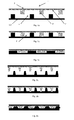
- FIG. 6a schematically shows the structure of a first embodiment of the sensor mat according to the invention according to variant b) in cross section and in an exploded view.
- the illustrated volumenkompressible flexible sensor mat 1 consists of two superimposed elastomer layers 6 and 7.
- the two elastomer layers 6 and 7 are in Fig. 6a not yet joined, ie the mat is in a non-finished (manufacturing) state (exploded view).
- a first, according to variant b) of the invention provided electrically conductive elastomer layer 7 (one of the two measuring electrodes) is porous and thus volume compressible. It is complete in the above sense - d. H. optionally additionally divided by lateral structuring into a plurality of electrodes in the mat surface - formed electrically conductive and thus represents an electrode (schematically indicated by black color).
- Another, second elastomer layer 6 is not electrically conductive; it has on its outside with respect to the first elastomer layer 7 a thin electrode layer 3 (schematically, i.e. not to scale, shown in black).
- lateral structuring of one or both electrodes 3 and 7, ie a division along the mat surface into electrically independent or mutually coupled / connected local electrodes, is also possible in this example (not shown).
- FIG. 6b shows schematically the structure of the same volume-compressible flexible sensor mat 1 in the assembled, ie finished state, in which the two elastomer layers 6 and 7 touch, but are not compressed.
- the mat 1 is not loaded here or not deformed.
- the first elastomeric layer (electrode) 7 are gas-filled pores 5 from which the gas can escape during compression of the mat 1 (open porosity) or in which it is compressed (closed porosity).
- FIGS. 7a and 7b show a second embodiment of the sensor mat according to the invention 1 according to variant b) in cross section. This is different from the one in Fig. 6 shown example in that not only the first elastomer layer 7 (electrode) is porous, but also the second elastomer layer 8 (dielectric) is porous.
- the second elastomer layer 8 contains on its side facing away from the first elastomer layer 7 side, a conductive coating 3 (counter electrode).
- FIGS. 8a and 8b show a third embodiment of the sensor mat according to the invention 1 according to variant b) in cross section. This is different from the one in Fig. 7 Example shown only in that both electrodes 3 and 7 of the two elastomer layers 7 and 8 on their respective side facing away from the other elastomer layer side - ie outside the finished sensor mat in Fig. 8b - Have a non-conductive protective layer 9.
- FIG. 9 shows top views of a sensor mat according to the invention 1 with a structured square electrode surface 3, which forms a one-dimensional rectangular array 10.
- the electrodes 3 are aligned on an upper side surface of the mat 1 along the image plane and in Fig. 9b ), the counter electrodes 3 on the back of the sensor mat 1 are aligned transversely thereto.
- a separate pressure measurement on the individual two-dimensionally distributed electrode fields 10, 11 see. Fig. 10 ).
- the FIGS. 9a and 9b can serve as examples of a plan view from above or from below onto a sensor mat according to the invention both according to variant a) and according to variant b), ie with the structured electrode layers 3 arranged on both sides on an elastomer mat 1.
- FIG. 10 shows a projecting plan view of a sensor mat according to the invention 1 as in FIG. 9 , which is covered on both sides in each case with a one-dimensionally structured electrode surface 3, which form a two-dimensional electrode pair array 11. This is a separate contact and thus capacitance measurement on the individual electrode fields 11th allows.
- FIG. 9 this figure can also be seen as an example of the sensor mat 1 according to both variants according to the invention.
Landscapes
- Physics & Mathematics (AREA)
- General Physics & Mathematics (AREA)
- Engineering & Computer Science (AREA)
- Power Engineering (AREA)
- Force Measurement Appropriate To Specific Purposes (AREA)
Abstract
Die Erfindung betrifft eine volumenkompressible kapazitive flächige flexible Sensormatte zur Messung/Erfassung von Druck oder Deformationen bzw. deren Verteilung auf flexiblen flächigen Unterlagen, die mindestens zwei Elektroden aufweist, zwischen denen die elektrische Kapazität gemessen werden kann, und entweder
(a) eine flächige Elastomermatte darstellt, die aus zwei in Richtung senkrecht zu der Matte übereinander angeordneten Elastomerschichten zusammengesetzt ist, dergestalt dass
(i) eine erste Elastomerschicht auf ihrer der zweiten Elastomerschicht zugewandten Flächenseite ein unebenes Profil mit Erhöhungen und/oder Vertiefungen aufweist, wobei das Profil mit einer Elektrodenschicht bedeckt ist oder die erste Elastomerschicht vollständig elektrisch leitfähig ausgebildet ist,
(ii) die zweite Elastomerschicht auf ihrer der ersten Elastomerschicht zugewandten Flächenseite entweder ein ebenes Profil oder ein unebenes Profil mit Erhöhungen aufweist, das zum Profil der ersten Elastomerschicht teilweise komplementär ist, während ihre andere, von der ersten Elastomerschicht abgewandte Flächenseite mit einer Elektrodenschicht bedeckt ist, wobei
(iii) in einem entlasteten Zustand der Sensormatte zwischen den Elastomerschichten in den Bereichen zwischen den Erhöhungen mindestens ein Hohlraum vorliegt, in den das Elastomermaterial beim Zusammendrücken der Sensormatte ausweichen kann,
oder
(b) eine flächige Elastomermatte mit darin angeordneten Poren darstellt, wobei sich die mindestens zwei Elektroden in Form elektrisch leitfähiger Elektrodenschichten entlang der beiden Flächenseiten der Matte erstrecken und mindestens eine der Elektroden eine elektrisch leitfähig ausgebildete poröse Elastomerschicht oder einen elektrisch leitfähig ausgebildeten Teil einer porösen Elastomerschicht umfasst, dergestalt, dass bei einer Druckbelastung der Sensormatte infolge einer damit einhergehenden Reduktion des Volumens des mindestens einen Hohlraums bzw. der Poren der Abstand zwischen den mindestens zwei Elektroden verringert wird, derart dass sich dadurch die elektrische Kapazität messbar erhöht.

(A) represents a flat elastomer mat, which is composed of two in the direction perpendicular to the mat superimposed elastomer layers, such that
(i) a first elastomer layer has an uneven profile with elevations and / or depressions on its surface side facing the second elastomer layer, wherein the profile is covered with an electrode layer or the first elastomer layer is completely electrically conductive,
(ii) the second elastomer layer has on its surface facing the first elastomeric layer either a planar profile or an uneven profile with ridges which is partially complementary to the profile of the first elastomeric layer while its other surface side remote from the first elastomeric layer is covered with an electrode layer , in which
(iii) in a relieved state of the sensor mat between the elastomeric layers in the areas between the elevations there is at least one cavity into which the elastomeric material can escape when the sensor mat is compressed,
or
(B) represents a flat elastomer mat with pores therein, wherein the at least two electrodes extend in the form of electrically conductive electrode layers along the two surface sides of the mat and at least one of the electrodes an electrically conductive porous elastomer layer or an electrically conductive formed part of a porous elastomer layer comprises, in such a way that is reduced at a pressure load of the sensor mat due to a concomitant reduction in the volume of the at least one cavity or the pores, the distance between the at least two electrodes, such that thereby increases the electrical capacitance measurably.
Description
Die Erfindung betrifft eine volumenkompressible kapazitive flächige flexible Sensormatte zur Messung von Druck oder Druckverteilungen und/oder zur Messung oder Detektion von Deformationen auf flexiblen flächigen Unterlagen, welche Sensormatte mindestens zwei Elektroden aufweist, zwischen denen die elektrische Kapazität gemessen werden kann, und dergestalt ausgebildet ist, dass bei einer Druckbelastung der Sensormatte sich die elektrische Kapazität messbar - und bei Bedarf auch ortsaufgelöst - erhöht.The invention relates to a volume-compressible capacitive flat flexible sensor mat for measuring pressure or pressure distributions and / or for measuring or detecting deformations on flexible sheet-like substrates, which sensor mat has at least two electrodes, between which the electrical capacitance can be measured, and is designed in such a way that at a pressure load of the sensor mat, the electrical capacitance measurably - and, if necessary, also spatially resolved - increases.
Der Begriff "flächig" deutet im Rahmen der vorliegenden Erfindung allein auf die zweidimensionale Ausdehnung der Sensormatte hin, sodass die Sensormatte über zwei äußere Flächenseiten/Oberflächen verfügt, auf mindestens einer von welchen die Sensormatte dem zu messenden/detektierenden Druck oder der zu messenden/detektierenden Deformation ausgesetzt werden kann. Der Begriff "flächig" soll jedoch nicht als einschränkend auf eine ebene geometrische Form dieser Flächenseite oder auf eine flache/dünne Ausgestaltung der Sensormatte verstanden werden, wenngleich solche Ausführungsformen auch mitumfasst sind. Das Gleiche gilt auch für Elemente der Sensormatte, die im Folgenden als "flächig" bezeichnet werden.In the context of the present invention, the term "planar" refers solely to the two-dimensional extent of the sensor mat so that the sensor mat has two outer surface sides / surfaces, on at least one of which the sensor mat is the pressure to be measured or detected or the one to be measured / detected Deformation can be suspended. However, the term "planar" is not to be understood as limiting to a planar geometric shape of this surface side or to a flat / thin configuration of the sensor mat, although such embodiments are also included. The same applies to elements of the sensor mat, which are referred to below as "flat".
Gegenüber bekannten Druck- und Deformationssensoren richtet sich die vorliegende Erfindung auf eine Verbesserung der Sensorempfindlichkeit für geringfügige Druck- oder Deformationsänderungen bei einer von der Herstellung her einfachen und günstigen, aber zugleich hinsichtlich der Anpassungsfähigkeit an die Erfordernisse der jeweiligen Anwendung - wie etwa an eine erforderliche Ortsauflösung - leistungsfähigeren Konstruktion des Sensors.Compared to known pressure and deformation sensors, the present invention is directed to an improvement of the sensor sensitivity for minor changes in pressure or deformation at a simple and inexpensive from the production ago, but at the same time in terms of adaptability to the requirements of the particular application - such as a required spatial resolution - more powerful design of the sensor.
In vielen verschiedenen Situationen ist es beispielsweise erforderlich, auf einer flexiblen, d. h. nachgiebigen/verformbaren, flächigen Unterlage die von einem aufliegenden Körper auf die Unterlage ausgeübte Druckverteilung zu messen. Dies ist in solchen Anwendungen besonders relevant, bei denen der Druck auf die Unterlage durch das Gewicht einer Person erzeugt wird.For example, in many different situations it is necessary to work on a flexible, d. H. flexible / deformable, flat surface to measure the pressure distribution exerted by an overlying body on the pad. This is particularly relevant in those applications where the pressure on the pad is created by the weight of a person.
Ein Beispiel mit großer technischer Bedeutung ist die Sensorik in einem Autositz, mit der die Druckverteilung der darauf sitzenden Person registriert wird. Damit kann nicht nur die Belegung des Sitzes erkannt, sondern auch das Gewicht der Person ermittelt und zusätzlich die Verteilung ihres Gewichtes auf der Sitzfläche erfasst werden. Die Kenntnis dieser Daten kann bei einem Unfall eine erhebliche Bedeutung für die Ansteuerung eines Airbags haben. Durch eine auf die Größe, das Gewicht und/oder die aktuelle Sitzposition abgestimmte Auslösung des Airbags kann z. B. zwischen einem Kind und einem Erwachsenen unterschieden werden und Verletzungen können unter Umständen vermieden oder verringert werden.An example of great technical importance is the sensor system in a car seat, with which the pressure distribution of the person sitting on it is registered. This not only detects the occupancy of the seat, but also determines the weight of the person and in addition the distribution of their weight on the seat can be detected. The knowledge of this data can have a significant importance for the control of an airbag in an accident. By tuned to the size, weight and / or the current seating position triggering the airbag z. B. between a child and an adult can be distinguished and injuries can be avoided or reduced under certain circumstances.
Ein weiterer wichtiger Anwendungsfall für ein solches Sensorsystem zur Messung einer flächigen Druckverteilung ist die Auflage einer bewegungsunfähigen Person in einem Bett. Hier ist es erforderlich, Stellen mit hoher Druckbelastung des Körpers zu erkennen und gezielt zu entlasten, da andernfalls schwer heilende Wunden entstehen können (Dekubitus). Eine ähnliche Situation ergibt sich für einen Querschnittsgelähmten auf der Sitzfläche seines Rollstuhls. Weiterhin ist es beispielsweise für Diabetes-Patienten sehr wichtig, beim Stehen die Druckverteilung des Fußes im Schuh zu erfassen, da auch hier schwere Schäden bis hin zur Erfordernis einer Amputation entstehen können.Another important application for such a sensor system for measuring a two-dimensional pressure distribution is the placement of a person unable to move in a bed. Here it is necessary to detect areas with high pressure load of the body and to relieve targeted, otherwise hard-healing wounds may arise (pressure ulcers). A similar situation arises for a paraplegic on the seat of his wheelchair. Furthermore, it is very important, for example for diabetic patients, to detect the pressure distribution of the foot in the shoe when standing, since severe damage up to the requirement for amputation can also occur here.
Für die Messung eines mechanischen Druckes stehen eine große Auswahl von Messmethoden und entsprechende Sensoren zur Verfügung. Wenn jedoch die Druckverteilung auf einer großen Fläche erfasst werden soll, ist dies mit einem hohen Aufwand verbunden, denn dafür muss eine Vielzahl von Sensoren eingesetzt werden. Noch schwieriger zu realisieren ist die Druckmessung auf einer flexiblen, d. h. nachgiebigen/verformbaren, Unterlage, weil die Sensoranordnung der Verformung der Unterlage folgen und sich dabei in der Regel in gewissen Grenzen auch lateral dehnen muss.For the measurement of a mechanical pressure, a large selection of measuring methods and corresponding sensors are available. However, if the pressure distribution on a large area to be detected, this is associated with a lot of effort, because a variety of sensors must be used. Even more difficult to realize is the pressure measurement on a flexible, d. H. compliant / deformable, pad, because the sensor assembly to follow the deformation of the pad and thereby usually has to stretch laterally within certain limits.
Druck- und Deformationssensoren sind aus dem Stand der Technik bekannt. So offenbart
Bisher stehen nur wenige Sensorsysteme zur Verfügung, mit denen Druckverteilungen auf flexiblen Unterlagen prinzipiell gemessen werden können, z. B. auf der Messung der Leitfähigkeit basierende Systeme. Diese sind jedoch technisch äußerst aufwendig, dementsprechend kostspielig und können daher das breite Feld der alltäglichen Anwendungen, von welchem in den obigen Beispielen nur ein Teil aufgezeigt wurde, nicht oder nur sehr eingeschränkt bedienen.So far, only a few sensor systems are available with which pressure distribution on flexible documents can be measured in principle, z. B. on the measurement of conductivity based systems. However, these are technically extremely expensive, therefore expensive and therefore can not or only very limited serve the broad field of everyday applications, of which in the above examples only a part has been shown.
In einem Beitrag auf
In einer Veröffentlichung von
Neben Sensoren zur verbesserten Messung bzw. Detektion von Druck oder Druck- und/oder Deformationsverteilungen auf flexiblen flächigen Unterlagen richtet sich die vorliegende Erfindung auch auf flächige Sensoren zur Erfassung oder Messung von Druck oder Druckverteilungen eines fluiden Mediums an einer Oberfläche. Als fluide Medien sind hier Gase und Flüssigkeiten, aber auch disperse Feststoffe wie rieselfähige Materialien und Pulver zu verstehen. Als Beispiel für die großflächige Messung der Luftdruckverteilung an einer Oberfläche wird die Luftströmung an Flugzeugtragflächen genannt. Auf diese Weise können Strömungsabrisse erkannt werden. Ein Beispiel für einen Drucksensor für Flüssigkeiten bildet ein Füllstandssensor, der etwa die Flüssigkeitsmenge in einem Behälter ermittelt. Schließlich möchte man bei der Verarbeitung von Pulvern mitunter wissen, welchen Druck eine Pulvermischung auf die Unterlage ausübt, denn dieser Druck ergibt sich aufgrund von Wechselwirkungskräften zwischen den Pulverpartikeln nicht einfach aus dem Gewicht des auf der Unterlage aufliegenden Pulvers.In addition to sensors for improved measurement or detection of pressure or pressure and / or deformation distributions on flexible sheet-like documents, the present invention is also directed to planar sensors for detecting or measuring pressure or pressure distributions of a fluid medium on a surface. As fluid media are here gases and liquids, but also to understand disperse solids such as free-flowing materials and powders. As an example of the large-scale measurement of the air pressure distribution on a surface, the air flow is called at aircraft wings. In this way, stalls can be detected. An example of a pressure sensor for liquids is a level sensor, which determines approximately the amount of liquid in a container. Finally, when processing powders, one sometimes wants to know what pressure a powder mixture exerts on the substrate, because this pressure does not simply result from the weight of the powder resting on the substrate due to interaction forces between the powder particles.
Für die Druckmessung von fluiden Medien gibt es Sensoren, die mit verschiedenen Messprinzipien arbeiten. Zu nennen sind Dehnmessstreifen und auch kapazitive Sensoren, die verformbare Metallmembranen als Elektroden enthalten. Piezoelektrische Drucksensoren können keine statischen, sondern nur dynamische Drucksignale messen. Die bestehenden Drucksensoren eignen sich eher zur Messung auf kleinen Flächen. Zudem handelt es sich nicht um sehr kostengünstige Lösungen.For the pressure measurement of fluid media, there are sensors that work with different measuring principles. These include strain gauges and capacitive sensors that contain deformable metal membranes as electrodes. Piezoelectric pressure sensors can not measure static but only dynamic pressure signals. The existing pressure sensors are more suitable for measurements on small surfaces. Moreover, these are not very cost effective solutions.
Die eingangs genannte Aufgabe der Erfindung wird durch eine volumenkompressible, kapazitive, flächige, flexible Sensormatte gelöst, die mindestens zwei Elektroden aufweist, zwischen denen die elektrische Kapazität gemessen werden kann, und entweder
- (a) eine flächige Elastomermatte darstellt, die aus zwei in Richtung aus der Sensormatte (d. h. im weitesten Sinne "senkrecht" auf eine lokale Sensormattenfläche) übereinander (z. B. im weitesten Sinne "parallel" zueinander) angeordneten - und in der Regel an einer oder mehreren Punktstellen aneinander anliegenden - Elastomerschichten zusammengesetzt ist, dergestalt dass
- (i) eine erste Elastomerschicht auf ihrer der zweiten Elastomerschicht zugewandten Flächenseite/Oberfläche ein unebenes Profil mit Erhöhungen/Vorsprüngen und/oder Vertiefungen/Ausnehmungen aufweist, wobei das Profil mit einer - vorzugsweise lateral dehnbaren - Elektrodenschicht bedeckt ist oder aber die erste Elastomerschicht vollständig elektrisch leitfähig ausgebildet ist und somit eine Elektrode bildet,
- (ii) die zweite Elastomerschicht, die selbst in der Regel nicht elektrisch leitend (d. h. vielmehr dielektrisch) ist, auf ihrer der ersten Elastomerschicht zugewandten Flächenseite/Oberfläche entweder ein ebenes Profil oder ein unebenes Profil mit Erhöhungen/Vorsprüngen bzw. Vertiefungen/Ausnehmungen aufweist, das zum Profil der ersten Elastomerschicht teilweise komplementär ist, während ihre andere, von der ersten Elastomerschicht abgewandte Flächenseite/Oberfläche mit einer - vorzugsweise lateral dehnbaren - Elektrodenschicht bedeckt ist, wobei
- (iii) in einem entlasteten Zustand der Sensormatte zwischen den Elastomerschichten in den Bereichen zwischen den Erhöhungen bzw. um die Erhöhungen herum mindestens ein Hohlraum vorliegt, in den das Elastomermaterial beim Zusammendrücken der Sensormatte ausweichen kann,
- (b) eine flächige Elastomermatte mit darin angeordneten Poren darstellt, die eine oder mehrere - in der Regel in Richtung aus der Sensormatte (d. h. im weitesten Sinne "senkrecht" auf eine lokale Sensormattenfläche) übereinander (z. B. im weitesten Sinne "parallel" zueinander) angeordnete - flächige poröse Elastomerschicht(en) aufweist, wobei sich die mindestens zwei Elektroden in Form elektrisch leitfähiger Elektrodenschichten entlang der beiden Flächenseiten der Elastomermatte erstrecken
und wobei mindestens eine dieser Elektroden eine vollständig elektrisch leitfähig ausgebildete poröse Elastomerschicht oder einen vollständig elektrisch leitfähig ausgebildeten Teil (etwa eine Teilschicht) einer porösen Elastomerschicht darstellt oder umfasst,
- (a) represents a two-dimensional elastomer mat, which from two in the direction of the sensor mat (ie in the broadest sense "perpendicular" to a local sensor mat surface) on top of each other (eg, in the broadest sense "parallel") arranged - and usually at one or more point locations of adjoining elastomer layers is composed in such a way that
- (i) a first elastomeric layer has an uneven profile with elevations / projections and / or depressions / recesses on its surface side / surface facing the second elastomeric layer, the profile being covered with an electrode layer, preferably laterally expandable, or the first elastomer layer being completely electrically conductive is conductive and thus forms an electrode,
- (ii) the second elastomer layer, which itself is generally not electrically conductive (ie rather dielectric), has on its surface facing the first elastomer layer / surface either a flat profile or an uneven profile with elevations / protrusions or recesses, which is partially complementary to the profile of the first elastomeric layer, while its other surface side / surface facing away from the first elastomeric layer is covered with an electrode layer, preferably laterally expandable, wherein
- (iii) in a relieved state of the sensor mat between the elastomer layers in the areas between the elevations or around the elevations there is at least one cavity into which the elastomer material can escape when the sensor mat is compressed,
- (b) represents a flat elastomer mat with pores disposed therein, one or more - usually in the direction of the sensor mat (ie in the broadest sense "perpendicular" to a local sensor mat surface) on top of each other (eg, in the broadest sense "parallel" to each other) arranged - having surface porous elastomer layer (s), wherein the at least two electrodes extend in the form of electrically conductive electrode layers along the two surface sides of the elastomer mat
and wherein at least one of these electrodes is or comprises a completely electrically conductive porous elastomer layer or a completely electrically conductive part (for example a partial layer) of a porous elastomer layer,
Kapazitätsänderungen bis über 100 % sind dabei möglich. Diese Kapazitätserhöhung kann mit einem einfachen Messverfahren in einer dem Fachmann bekannten Weise erfasst werden.Capacity changes up to more than 100% are possible. This increase in capacity can be detected by a simple measuring method in a manner known to those skilled in the art.
Die volumenkompressible kapazitive flächige flexible Sensormatte nach der Erfindung kann insbesondere die Ausgestaltung gemäß Anspruch 1 besitzen.The volume-compressible capacitive flat flexible sensor mat according to the invention may in particular have the configuration according to
Die erfindungsgemäße flächige flexible volumenkompressible Sensormatte (im Folgende auch kurz als Matte bezeichnet) stellt daher einen Kondensator oder - bei mehreren Elektrodenpaaren - ein System von mehreren Kondensatoren dar, dessen/deren Kapazität (ggf. jeweils) von der Fläche der Elektroden und von deren Abstand zueinander abhängt. Durch die in der Matte vorgesehenen Hohlräume/Poren wird diese volumenkompressibel und kann daher relativ leicht zusammengedrückt werden. Durch das Verformen/Zusammendrücken der erfindungsgemäßen Sensormatte in Richtung senkrecht zu der/den Elastomerschichten wird der Abstand zwischen den Elektroden - ggf. lokal - verringert und je nach Elektrodengeometrie in spezifischen Ausgestaltungen ggf. zugleich auch deren Fläche vergrößert, was zu einem erfindungsgemäß deutlichen Anstieg der zwischen den Elektroden - ggf. lokal bzw. ortsaufgelöst - gemessenen Kapazität führt.The flat flexible volumenkompressible sensor mat according to the invention (hereinafter also referred to briefly as a mat) therefore represents a capacitor or - in the case of several pairs of electrodes - a system of several capacitors, whose / their capacity (possibly each) of the surface of the electrodes and their distance depends on each other. By provided in the mat cavities / pores, this volume is compressible and therefore can be relatively easily compressed. By deforming / compressing the sensor mat according to the invention in the direction perpendicular to the elastomer layer (s), the distance between the electrodes is reduced, if necessary locally, and, depending on the electrode geometry, in specific embodiments, at the same time also its area is increased, which leads to a significant increase in the invention between the electrodes - possibly locally or spatially resolved - measured capacity leads.
Der oder die Hohlräume/Poren sind in einem einfachen Fall gasgefüllt, z. B. mit Luft oder einem inerten Gas. Wenn die Sensormatte zusammengedrückt wird, kann das Gas - je nach Ausführungsform - aus den (nach außen offenen) Hohlräumen/Poren seitlich aus der Matte an ihren Stirnseiten entweichen oder aber in (nach außen geschlossenen) Hohlräumen verbleiben und dem Druck durch die hohe Kompressibilität des Gases nachgeben. Es sind auch Kombinationen dieser beiden Möglichkeiten in einer Matte möglich. In spezifischen Ausführungsformen können sich darüber hinaus auch nicht gasförmige Stoffe in den Hohlräumen befinden oder diese ausfüllen, wie z. B. komprimierbare Feststoffe, wie etwa Schaumstoffe, oder zum Entweichen aus der Matte geeignete Stoffe, wie etwa Flüssigkeiten. Dabei hängt die Kompressibilität von der Härte des verwendeten Elastomers sowie vom Volumenverhältnis der Hohlräume bzw. Poren und des Elastomermaterials ab. Vorteile der erfindungsgemäßen Sensormatte im Hinblick auf die Empfindlichkeit einer Druck- bzw. Deformationsmessung und auf den zugänglichen Messbereich werden zunächst einmal aus dem Vergleich mit dielektrischen Elastomerfolien deutlich, welche bereits bekannt sind. Eine dielektrische Elastomerfolie besteht aus einer stark dehnbaren Elastomerfolie, die beidseitig mit ebenfalls stark dehnbaren Elektroden beschichtet ist. Die Elektroden behalten auch bei einer hohen Dehnung eine ausreichende elektrische Leitfähigkeit bei. Eine solche dielektrische Elastomerfolie hat damit die Form eines Kondensators, dessen Kapazität von der Fläche der Elektroden und der Dicke der dazwischen liegenden Elastomerfolie abhängt. Wird die dielektrische Elastomerfolie gedehnt, so vergrößert sich die Elektrodenfläche und verringert sich zugleich der Elektrodenabstand. Beides führt zu einer Kapazitätserhöhung. Damit wirkt die dielektrische Elastomerfolie wie ein kapazitiver Dehnungssensor.The one or more cavities / pores are gas filled in a simple case, e.g. B. with air or an inert gas. If the sensor mat is compressed, the gas - depending on the embodiment - escape from the (outwardly open) cavities / pores laterally from the mat at their ends or remain in (closed to the outside) cavities and the pressure due to the high compressibility of the Giving in gas. There are also combinations of these two possibilities in a mat possible. In specific embodiments, in addition, non-gaseous substances may be in the cavities or fill them, such. Compressible solids, such as foams, or fabrics suitable for escape from the mat, such as liquids. The compressibility depends on the hardness of the elastomer used and on the volume ratio of the cavities or pores and the elastomer material. Advantages of the sensor mat according to the invention with regard to the sensitivity of a pressure or deformation measurement and to the accessible measuring range are first of all clear from the comparison with dielectric elastomer foils, which are already known. A dielectric elastomeric film consists of a highly stretchable elastomeric film, which is coated on both sides with equally strong elastic electrodes. The electrodes retain sufficient electrical conductivity even at high elongation. Such a dielectric elastomeric film thus has the form of a capacitor whose capacitance depends on the area of the electrodes and the thickness of the elastomeric film therebetween. If the dielectric elastomer film is stretched, the electrode area increases and, at the same time, the electrode spacing decreases. Both lead to an increase in capacity. Thus, the dielectric elastomeric film acts as a capacitive strain sensor.
Bei der Auflage einer dielektrischen Elastomerfolie auf einer nachgiebigen Unterlage, wie z. B. einem Sitz, ist die sich bei einer Druckbelastung einstellende Dehnung der Folie jedoch äußerst gering und damit die Empfindlichkeit einer Kapazitätsmessung kaum ausreichend. Das hängt damit zusammen, dass die dielektrische Elastomerfolie weitgehend volumeninkompressibel ist. Beim Zusammendrücken der Folie weicht das Elastomermaterial zur Seite aus, wodurch sich die Folienfläche vergrößert. Dies ist allerdings mit einem hohen mechanischen Widerstand verbunden, d. h. der Sensor reagiert auf mechanischen Druck auf die Folie nur äußerst unempfindlich.When applying a dielectric elastomeric film on a resilient base, such. As a seat, which is at a pressure load adjusting elongation of the film, however, extremely low and thus the sensitivity of a capacitance measurement is hardly sufficient. This is due to the fact that the dielectric elastomer film is largely volume incompressible. When compressing the film, the elastomeric material deviates to the side, which increases the film surface. However, this is associated with a high mechanical resistance, i. H. The sensor reacts very insensitive to mechanical pressure on the film.
Bei einer erfindungsgemäßen Sensormatte für nachgiebige Unterlagen dienen demgegenüber die zusammendrückbaren Hohlräume/Poren dazu, dass die Verringerung des Elektrodenabstands eines Elektrodenpaares und damit die erfassbare Kapazitätsänderung bei einer geringen Druckbelastung der Matte - wie z. B. bei einer lokalen Druckerhöhung oder einer lokalen Deformation wie Stauchung - erheblich höher ausfällt.In a sensor mat according to the invention for yielding documents on the other hand, the compressible cavities / pores serve to reduce the electrode spacing of a pair of electrodes and thus the detectable capacitance change at a low pressure loading of the mat - such. B. at a local pressure increase or a local deformation such as compression - significantly higher.
Ferner ist bei der Sensormatte nach der Erfindung der Elektrodenabstand im unbelasteten Zustand der Matte und damit der zugängliche Messbereich und die Messempfindlichkeit in den meisten Ausgestaltungen nicht unmittelbar durch die Dicke des wegen der Hohlräume/Poren volumenkompressiblen Elastomermaterials vorgegeben, im Unterschied etwa zu dem aus der obigen Veröffentlichung von Riedl et al. bekannten kapazitiven Drucksensor, der ebenfalls Hohlräume zwischen den Erhöhungen der dielektrischen Schicht aufweist. Vielmehr ist bei der erfindungsgemäßen Sensormatte der Abstand der Messelektroden im entlasteten Zustand der Matte - ggf. lokal - deutlich kleiner als die Gesamtdicke der Sensormatte/Elastomermatte und kann - je nach Ausführungsform - z. B. nur einen Bruchteil der Mattendicke betragen. Die erfindungsgemäße Konstruktion bleibt jedoch ganz ohne Einbuße bei den elastischen Eigenschaften (Elastizitätsmodul, ggf. laterale Dehnbarkeit etc.) der Matte, weil nach der Erfindung mindestens eine der Messelektroden - zumindest zum Teil - selbst als eine mit Erhöhungen/Hohlräumen bzw. Poren versehene und dadurch volumenkompressible Elastomerschicht ausgestaltet und bei einer Druckbelastung des Sensors zu einem erheblichen Teil an seiner Komprimierbarkeit beteiligt ist. Daraus resultiert unter anderem eine vorteilhafte Entkopplung/Freiheit bei der Einstellung/Wahl von elektrischen einerseits und mechanischen andererseits Eigenschaften der Sensormatte. Mit anderen Worten kann eine diese Eigenschaften betreffende Anpassung des erfindungsgemäßen Sensors an die jeweilige Anwendung in einem sehr breiten Intervall durch eine einfache Geometrieänderung (etwa Dicke, Porengröße oder Profilform) bei den elektrisch leitenden und/oder isolierenden Elastomerschichten erfolgen, d. h. ohne eine grundsätzliche Änderung der Sensorkonstruktion und damit äußerst kostengünstig und flexibel.Furthermore, in the sensor mat according to the invention, the electrode spacing in the unloaded state of the mat, and thus the accessible measuring range and the measuring sensitivity in most embodiments, are not directly dictated by the thickness of the elastomeric material which is volume-compressible because of the cavities / pores, in contrast to that from the above Publication by Riedl et al. known capacitive pressure sensor, which also has cavities between the elevations of the dielectric layer. Rather, in the sensor mat according to the invention, the distance of the measuring electrodes in the unloaded state of the mat - possibly locally - significantly smaller than the total thickness of the sensor mat / elastomer mat and can - depending on the embodiment - z. B. amount to only a fraction of the mat thickness. However, the construction of the invention remains without loss of elastic properties (modulus of elasticity, possibly lateral extensibility, etc.) of the mat, because according to the invention, at least one of the measuring electrodes - at least in part - even as a with Elevations / cavities or pores provided and thus volume-compressible elastomer layer configured and involved in a compressive load of the sensor to a considerable extent on its compressibility. This results inter alia in an advantageous decoupling / freedom in the setting / choice of electrical on the one hand and mechanical properties of the other sensor mat. In other words, an adaptation of the sensor according to the invention to the respective application in a very wide interval by a simple change in geometry (such as thickness, pore size or profile shape) in the electrically conductive and / or insulating elastomer layers, ie without a fundamental change of Sensor construction and thus extremely cost-effective and flexible.
Die mindestens zwei Elektroden bzw. Elektrodenschichten können sich in einer erfindungsgemäßen flächigen Sensormatte in einem einfachen Fall jeweils über die gesamte Fläche der Matte bzw. einer Elastomerschicht erstrecken. Es können jedoch Elektroden/Elektrodenschichten eingesetzt werden, die sich nur über eine bestimmte Teilfläche der Sensormatte erstrecken. Ferner kann es sich bei einer Elektrodenschicht um eine lateral strukturierte Elektrodenschicht mit mehreren in verschiedenen Flächensegmenten der Matte angeordneten und voneinander elektrisch unabhängigen oder elektrisch miteinander verbundenen/gekoppelten Elektroden zum Zwecke einer ortsaufgelösten Druck- bzw. Deformationsmessung mittels dementsprechend mehrerer über die Gesamtfläche der Matte verteilter Elektrodenpaare handeln. So können Elektrodenarrays auf den Erhöhungen/Vorsprüngen des Profils der ersten Elastomerschicht angeordnet sein, die beispielsweise reihenweise durch dem Profil der Schicht folgende, elektrisch leitende Streifen miteinander verbunden sind oder sogar einzeln elektrisch angesteuert werden können. Genauere Beispiele für diese verschiedenen Möglichkeiten folgen weiter unten. Bei der Beschreibung spezifischer Ausgestaltungen wird im Folgenden der Einfachheit halber meist von "Elektroden/Elektrodenschichten" die Rede sein, die eine Elastomerschicht "bedecken", sich entlang dieser "erstrecken", diese "ausfüllen" etc.. Dabei soll in allen Fällen neben einer vollständigen "Bedeckung", "Beschichtung", "Ausfüllung" etc. der jeweiligen Fläche/Schicht mit einer durchgehenden leitfähigen Elektrodenschicht/Elektrode stets in erster Linie eine teilweise, z. B. lokale, Bedeckung, Beschichtung, Ausfüllung etc. dieser Fläche/Schicht mit der Elektrode bzw. eine Bedeckung/Beschichtung/Ausfüllung mit einer wie angegeben lateral strukturierten Elektrode als möglich und als für die Erfindung besonders wichtig verstanden werden, ohne dass jedes Mal explizit darauf hingewiesen wird. Geeignete Materialien, chemische Elemente und Verbindungen sind weiter unten angegeben.In a simple sensor case, the at least two electrodes or electrode layers may each extend over the entire surface of the mat or an elastomer layer in a flat sensor mat according to the invention. However, it is possible to use electrodes / electrode layers which only extend over a specific partial area of the sensor mat. Furthermore, an electrode layer may be a laterally structured electrode layer with a plurality of electrodes arranged in different surface segments of the mat and electrically independent or electrically interconnected / coupled for the purpose of a spatially resolved pressure or deformation measurement by means of a plurality of electrode pairs distributed over the entire surface of the mat act. Thus, electrode arrays can be arranged on the elevations / projections of the profile of the first elastomer layer, which, for example, are connected to one another in series by the profile of the layer, electrically conductive strips or can even be electrically driven individually. More specific examples of these different options follow below. In the description of specific embodiments, for the sake of simplicity, the term "electrodes / electrode layers" will be referred to below, which "cover" an elastomer layer, "extend" along it, "fill in" it complete "covering", "coating", "filling" etc. of the respective surface / layer with a continuous conductive electrode layer / electrode always primarily a partial, z. As local, covering, coating, filling, etc. of this surface / layer with the electrode or a cover / coating / filling with a laterally structured as indicated electrode as possible and as particularly important for the invention understood without each time explicitly is pointed out. Suitable materials, chemical elements and compounds are given below.
Insbesondere soll der Begriff "vollständig elektrisch leitfähig" eine laterale Strukturierung der durch die jeweilige Elastomerschicht gebildeten Elektrode zur Ausbildung von in der Sensormattenfläche elektrisch voneinander unabhängigen Elektroden nicht ausschließen. Vielmehr bezieht sich der Begriff "vollständig" in erster Linie auf die Dicke der betreffenden Elastomerschicht. Die elektrische Leitfähigkeit kann beispielsweise durch das Ausfüllen der Elastomermatrix mit leitfähigen Partikeln mit einer Partikeldichte oberhalb der Perkolationsschwelle hergestellt werden. Geeignete Materialien, chemische Elemente und Verbindungen werden weiter unten angegeben.In particular, the term "completely electrically conductive" is not intended to exclude a lateral structuring of the electrode formed by the respective elastomer layer for the formation of electrodes which are electrically independent of one another in the sensor mat surface. Rather, the term "complete" refers primarily to the thickness of the respective elastomer layer. The electrical conductivity can be produced, for example, by filling in the elastomer matrix with conductive particles having a particle density above the percolation threshold. Suitable materials, chemical elements and compounds are given below.
Eine erfindungsgemäße Messelektrode, die eine vollständig elektrisch leitfähige volumenkompressible Elastomerschicht mit in Hohlräume ragenden Erhöhungen (Variante a)) bzw. mit Poren (Variante b)) darstellt oder umfasst, sollte ferner über eine für die Funktion der Sensormatte ausreichende Verformbarkeit (je nach Anwendung ggf. auch laterale Dehnbarkeit, siehe unten) ganz ohne Nachteil für die elektrische Leitfähigkeit verfügen. Dies kann z. B. mit einer entsprechend weit über der Perkolationsschwelle liegenden Dichte der elektrisch leitfähigen Partikel erreicht werden. Das Gleiche gilt entsprechend auch für die Ausführungsformen nach Variante a), bei denen ein unebenes Profil einer dielektrischen Elastomerschicht mit einer Elektrode bedeckt ist.A measuring electrode according to the invention, which represents or comprises a completely electrically conductive volume-compressible elastomer layer with protrusions (variant a)) or with pores (variant b)) protruding into cavities, should also have a deformability which is sufficient for the function of the sensor mat (depending on the application, if necessary also lateral extensibility, see below) without any disadvantage for the electrical conductivity. This can be z. B. can be achieved with a correspondingly far above the percolation threshold density of the electrically conductive particles. The same applies mutatis mutandis to the embodiments according to variant a), in which an uneven profile of a dielectric elastomer layer is covered with an electrode.
Bei einer Sensormatte nach der Erfindung wird in der einen oder den mehreren Elastomerschichten vorzugsweise überall ein und dasselbe Elastomermaterial verwendet. Dies ist von Vorteil zum einen wegen der Einfachheit der Herstellung, zum anderen wegen der identischen Eigenschaften, wie z. B. des Elastizitätsmoduls, der Temperaturabhängigkeit, der Materialalterung etc., von aus einem und demselben Elastomermaterial gefertigten Teilen des Sensors. Es können aber bei Bedarf auch zwei oder mehr verschiedene Elastomermaterialien innerhalb einer Elastomerschicht oder für jeweils verschiedene Elastomerschichten in einer Sensormatte kombiniert werden. Ebenfalls können in einer erfindungsgemäßen Sensormatte unterschiedlich stark vernetzte Elastomermaterialien verwendet werden, d. h. das gleiche Elastomermaterial, welches unterschiedlich stark vernetzt wird und dadurch Bereiche oder Elemente mit unterschiedlicher Härte im Sensor ausbildet. Wenn in der nachfolgenden Beschreibung der Kürze wegen die Rede von "dem/einem Elastomer(material)" ist, sollen stets auch Kombinationen mehrerer unterschiedlicher Elastomermaterialien (bzw. mit unterschiedlichen Vernetzungsgraden/Härten) als mitumfasst verstanden werden. Geeignete Materialien und chemische Verbindungen sind weiter unten angegeben.In a sensor mat according to the invention, preferably one and the same elastomer material is used in the one or more elastomer layers. This is advantageous on the one hand because of the simplicity of production, on the other hand because of the identical properties, such. As the modulus of elasticity, the temperature dependence, the material aging, etc., made of one and the same elastomeric material parts of the sensor. However, if desired, two or more different elastomeric materials can also be combined within one elastomeric layer or for different elastomeric layers in a sensor mat. Likewise, differently crosslinked elastomer materials can be used in a sensor mat according to the invention, i. H. the same elastomeric material, which is crosslinked to different degrees and thereby forms areas or elements with different hardness in the sensor. In the following description, for brevity, the term "elastomer (material)" is used, and combinations of several different elastomer materials (or with different degrees of crosslinking / curing) should always be understood as being included. Suitable materials and chemical compounds are given below.
Zur Lösung der eingangs genannten Aufgabe und zur Erzielung der teilweise oben und mit weiteren Einzelheiten auch nachfolgend angegebenen technischen Wirkungen schlägt die Erfindung zwei alternative Lösungsansätze für die Ausgestaltung der Sensormatte vor, Variante a) und Variante b), die im Folgenden ausführlicher erläutert werden.To achieve the object mentioned above and to achieve the technical effects partially given above and with further details, the invention proposes two alternative approaches to the design of the sensor mat, variant a) and variant b), which are explained in more detail below.
Bei der Variante a) weist die Sensormatte zwei flächige Elastomerschichten auf, die in Richtung aus der Fläche der Matte übereinander angeordnet sind. Eine erste dieser Elastomerschichten weist auf derjenigen ihrer beiden Oberflächen, die der zweiten Elastomerschicht zugewandt ist, ein unebenes Profil mit Erhöhungen/Vorsprüngen und/oder Vertiefungen auf. Diese erste Elastomerschicht ist im obigen Sinne vollständig elektrisch leitfähig oder auf der Profilseite mit einer - vorzugsweise dehnbaren - leitfähigen und ggf. strukturierten Schicht beschichtet und bildet damit eine der beiden Elektroden. Die zweite Elastomerschicht weist auf derjenigen ihrer beiden Oberflächen, die der ersten Elastomerschicht zugewandt ist, entweder ein ebenes oder ein ebenfalls unebenes Profil auf, während ihre andere Oberfläche oder ein Teil davon mit einer - vorzugsweise ebenfalls dehnbaren und ggf. strukturierten - elektrisch leitfähigen Elektrodenschicht bedeckt ist, die die - ggf. jeweilige - zweite Messelektrode bildet. Falls vorhanden, ist das genannte unebene Profil der zweiten Elastomerschicht zum Profil der ersten Elastomerschicht teilweise komplementär, d. h. beim Übereinanderlegen der beiden Profile zur Herstellung der Sensormatte greifen die Erhöhungen und Vertiefungen der beiden Elastomerschichten ineinander, wie es z.B. in den
Die erfindungsgemäße Sensormatte gemäß Variante b) stellt eine flächige volumenkompressible Elastomermatte mit Poren in deren Innerem und mindestens zwei Elektrodenschichten, von denen mindestens eine zumindest teilweise aus porösem Elastomermaterial ist, dar. Die Elastomermatte nach dieser Variante enthält somit mindestens eine poröse Elastomerschicht; durch die Poren in der Elastomermatte wird diese volumenkompressibel und kann daher relativ leicht zusammengedrückt werden. Es können grundsätzlich auch nichtporöse Elastomerschichten in einer Matte nach Variante b) enthalten sein, etwa wenn es zur Erfüllung spezifischer mechanischer Anforderungen an die Stabilität, laterale Dehnbarkeit, Festigkeit etc. der Matte in einer Anwendung zweckdienlich sein sollte.The inventive sensor mat according to variant b) is a flat volume-compressible elastomer mat with pores in the interior and at least two electrode layers, at least one of which is at least partially made of porous elastomer material. The elastomer mat according to this variant thus contains at least one porous elastomer layer; through the pores in the elastomer mat, this becomes volume-compressible and can therefore be compressed relatively easily. In principle, it is also possible for nonporous elastomer layers to be present in a mat according to variant b) such as when it should be useful in meeting specific mechanical requirements for stability, lateral extensibility, strength, etc. of the mat in an application.
In einem einfachen Fall hat die Elastomermatte eine Schaumstruktur, die erfindungsgemäß auf einer ihrer Flächenseiten bis zu einer gewissen Dicke elektrisch leitfähig ist, während zwischen den beiden Messelektroden des jeweiligen Kondensators stets auch eine elektrisch isolierende poröse Elastomerschicht oder Teilschicht vorliegt. Die Messelektrode auf der anderen Mattenfläche kann dabei entweder ebenfalls eine leitfähige poröse Elastomerschicht sein/umfassen oder lediglich eine dünne elektrisch leitende Beschichtung der Matte darstellen.In a simple case, the elastomer mat has a foam structure which according to the invention is electrically conductive up to a certain thickness on one of its surface sides, while an electrically insulating porous elastomer layer or partial layer is always present between the two measuring electrodes of the respective capacitor. The measuring electrode on the other mat surface can either be a conductive porous elastomer layer or can comprise only a thin electrically conductive coating of the mat.
Allgemeiner weist die Elastomermatte in allen Fällen nach der Variante b) auf einer ihrer Flächenseiten eine poröse Elastomerschicht auf, die vollständig - und ggf. lateral strukturiert - elektrisch leitend ist und - ggf. mit weiteren elektrisch leitenden und/oder schützenden Schichten bedeckt - als eine der beiden Messelektroden des Kondensators fungiert. In allen Fällen nach Variante b) liegt zwischen den beiden Messelektroden des erfindungsgemäßen Kondensators auch eine elektrisch isolierende - in der Regel poröse - Elastomerschicht oder Teilschicht. Die Messelektrode auf der anderen Oberfläche der Sensormatte kann dabei entweder ebenfalls eine leitfähige poröse Elastomerschicht darstellen/umfassen oder aber eine dünne elektrisch leitende Beschichtung der Matte sein (Herstellungsmöglichkeiten für dünne Elektrodenschichten werden weiter unten angegeben).More generally, the elastomer mat in all cases according to variant b) on one of its surface sides on a porous elastomer layer which is completely - and possibly laterally structured - electrically conductive and - optionally covered with further electrically conductive and / or protective layers - as a the two measuring electrodes of the capacitor acts. In all cases according to variant b) is between the two measuring electrodes of the capacitor according to the invention also an electrically insulating - usually porous - elastomer layer or partial layer. The measuring electrode on the other surface of the sensor mat can either likewise constitute / comprise a conductive porous elastomer layer or else be a thin electrically conductive coating of the mat (production options for thin electrode layers are specified below).
Eine poröse Elastomerelektrode in der Matte nach der Variante b) der Erfindung kann z. B. als eine separate, im obigen Sinne vollständig elektrisch leitfähige Elastomerschicht hergestellt werden und in einem fertigen Zustand (d. h. nach abgeschlossener Schäumung und Vernetzung) mit einer elektrisch isolierenden (dielektrischen) porösen Elastomerschicht in der Matte verklebt oder anderweitig mechanisch verbunden werden. Hierbei werden in der Regel dieselben Materialien für die Elastomerschicht und für die Elektrodenschicht eingesetzt. Deren chemische Ähnlichkeit verbessert dabei die Haftung der beiden Komponenten. Stattdessen kann die elektrisch leitfähige Schicht vor dem Verschäumen und vollständigen Vernetzen ohne Kleber oder sonstige Befestigungsmittel mit einer angrenzenden dielektrischen Elastomerschicht homogen verbunden werden, die ebenfalls in der Regel noch nicht verschäumt ist, worauf beide Schichten in fertigungstechnisch vorteilhafter Weise gemeinsam verschäumt und vernetzt werden. Alternativ kann eine im obigen Sinne vollständig elektrisch leitende poröse Elastomerschicht als Teilschicht einer ansonsten elektrisch isolierenden porösen Elastomerschicht hergestellt werden, etwa durch eine einseitige Zufuhr leitfähiger Partikel zu einer derartigen Gesamtschicht bei deren Herstellung. Der Begriff "Teilschicht" bezieht sich in der Regel auf die Dicke der Gesamtschicht, sodass die erhaltene Elastomergesamtschicht bis zu einer bestimmten Dicke elektrisch leitfähig und darüber hinaus elektrisch isolierend ist.A porous elastomeric electrode in the mat according to the variant b) of the invention can, for. Example, as a separate, in the above sense completely electrically conductive elastomer layer are prepared and glued in a finished state (ie after completion of foaming and crosslinking) with an electrically insulating (dielectric) porous elastomer layer in the mat or otherwise mechanically connected. In this case, the same materials are usually used for the elastomer layer and for the electrode layer. Their chemical similarity improves the adhesion of the two components. Instead, the electrically conductive layer before foaming and complete crosslinking without adhesive or other fastening means with an adjacent dielectric elastomer layer can be homogeneously connected, which is also usually not foamed, whereupon both layers are foamed together in a production advantageous manner and networked. Alternatively, in the above sense, a completely electrically conductive porous elastomer layer can be produced as a partial layer of an otherwise electrically insulating porous elastomer layer, for example by a one-sided supply of conductive particles to such a total layer during their production. The term "partial layer" generally refers to the thickness of the overall layer, so that the resulting total elastomer layer is electrically conductive up to a certain thickness and moreover electrically insulating.
In allen Fällen nach der Variante b) kann das Dickenverhältnis der (einseitig oder beidseitig in der erfindungsgemäßen Sensormatte vorliegenden) elektrisch leitenden zu den (im Inneren der Matte angeordneten) elektrisch isolierenden porösen Elastomerschichten z. B. 1:1, 2:1, 1:2, in spezifischen Ausführungsformen auch 3:1, 4:1, 5:1 oder sogar mehr, oder aber 1:3, 1:4, 1:5 oder noch weniger betragen.In all cases according to variant b), the thickness ratio of the (electrically conductive on one side or both sides present in the sensor mat according to the invention) to the (inside the mat arranged) electrically insulating porous elastomer layers z. B. 1: 1, 2: 1, 1: 2, in specific embodiments, 3: 1, 4: 1, 5: 1 or even more, or 1: 3, 1: 4, 1: 5 or even less ,
Die Porosität kann offen oder geschlossen sein. Zu den Seitenrändern der Elastomermatte hin können die Poren geöffnet, z. B. untereinander verbunden, sein. Letzteres kann zum seitlichen Entweichen von Gasen aus der Sensormatte bei deren Druckbelastung sogar erwünscht sein. Im Unterschied zu künstlich strukturierten Hohlräumen nach der Variante a) der Erfindung sind Poren in ihrer Größe und ihrer räumlichen Verteilung statistisch verteilt. Die Poren sind in der Regel z. B. rundlich oder in ihren Grenzbereichen abgerundet ausgebildet. Sie entstehen meist bei der Herstellung bzw. Vernetzung der Matrix der Elastomermatte.The porosity can be open or closed. To the side edges of the elastomer mat out the pores can be opened, z. B. interconnected, be. The latter may even be desirable for the lateral escape of gases from the sensor mat at the pressure load. In contrast to artificially structured cavities according to variant a) of the invention, pores are randomly distributed in their size and their spatial distribution. The pores are usually z. B. rounded or formed rounded in their boundary areas. They usually arise in the production or crosslinking of the matrix of the elastomer mat.
Es können in einer und derselben Elastomermatte nach Variante b) sowohl offene als auch geschlossene Poren vorliegen. Das Vorhandensein offener Poren in allen Schichten macht die Matte gasdurchlässig und damit atmungsaktiv, was für Anwendungen im häuslichen Bereich (in Stühlen oder Betten), für Autositze und insbesondere für medizinische Zwecke (als Sensormatte zur Vermeidung von Dekubitus u.dgl.) von Vorteil ist.Both open and closed pores may be present in one and the same elastomer mat according to variant b). The presence of open pores in all layers makes the mat gas-permeable and thus breathable, which is advantageous for domestic applications (in chairs or beds), for car seats and especially for medical purposes (as a pressure-ulcer for preventing bedsores and the like) ,
Eine oder mehrere nichtporöse Deck- oder Zwischenschichten können auf einer oder auf beiden Flächenseiten einer porösen Elastomerschicht eingesetzt werden, beispielsweise zur Verbesserung der Haftung einer Elektrodenschicht auf einer dielektrischen Elastomerschicht oder zur besseren Trennung einer elektrisch leitenden von einer angrenzenden isolierenden Elastomerschicht bzw. zur mechanischen Festigung/Stabilisierung der Matte.One or more nonporous top or intermediate layers may be used on one or both sides of a porous elastomeric layer, for example to improve the adhesion of an electrode layer to a dielectric elastomer layer or to better separate an electrically conductive layer from an adjacent insulating elastomer layer or for mechanical strengthening. Stabilization of the mat.
Bei den in der Elastomermatte zu deren Flächenseiten hin geschlossenen Poren kann es sich neben vollständig darin eingeschlossenen Poren insbesondere auch um zu einem Seitenrand der Elastomermatte hin geöffnete, beispielsweise schlauchartige Hohlräume handeln. Ein schlauchartiger Hohlraum kann insbesondere auf seinen beiden Enden am jeweiligen Seitenrand der flächigen Elastomermatte nach außen offen sein. Durch eine derartige seitliche Öffnung eines Hohlraums kann z. B. die Luft beim Zusammendrücken der Sensormatte daraus entweichen und beim Entlasten der Matte wieder hineindringen.In the case of the pores closed in the elastomer mat towards its surface sides, in addition to pores completely enclosed therein, it may in particular also be open to a lateral edge of the elastomer mat, for example tube-like cavities. A hose-like cavity can be open to the outside, in particular on its two ends on the respective side edge of the flat elastomer mat. By such a lateral opening of a cavity z. B. escape the air when squeezing the sensor mat from it and penetrate again when relieving the mat.
Insbesondere im Falle einer offenen Porosität trägt eine elektrisch nicht leitende poröse Elastomerschicht häufig eine dünne nichtporöse Zwischenschicht auf einer oder auf beiden ihren Flächenseiten, sodass z. B. das Elektrodenmaterial beim Beschichten nicht in die an einer Flächenseite neben den geschlossenen Poren ebenfalls vorhandenen offenen Poren eindringen kann. In der Regel wird auch die Zwischenschicht aus einem Elastomermaterial gefertigt, wodurch unter anderem die Geschlossenheit der Poren zu den Flächenseiten der Elastomermatte hin gewährleistet werden kann.In particular, in the case of an open porosity, an electrically non-conductive porous elastomer layer often carries a thin non-porous intermediate layer on one or both of its surface sides, so that e.g. B. the electrode material during coating can not penetrate into a surface side next to the closed pores also present open pores. In general, the intermediate layer is made of an elastomeric material, whereby, inter alia, the closure of the pores can be ensured to the surface sides of the elastomer mat out.
In besonderen Ausführungsformen der Erfindung besitzt die Sensormatte eine Ausgestaltung gemäß Variante a), bei der die Elektrodenschicht, die sich auf der Außenseite der zweiten Elastomerschicht befindet, und im Falle des Vorhandenseins einer (separaten) Elektrodenschicht auf dem Profil der ersten Elastomerschicht auch diese Elektrodenschicht, ihrerseits aus einer elektrisch leitfähig ausgebildeten porösen Elastomerschicht besteht/bestehen oder eine solche umfasst/umfassen. In diesen Ausgestaltungen der Erfindung kann bzw. können die Elektrodenschicht(en) jede Form und jedes Merkmal - einzeln oder in Kombination - besitzen, das in diesem Anmeldetext im Zusammenhang mit der Variante b) beschrieben wird.In particular embodiments of the invention, the sensor mat has a configuration according to variant a), in which the electrode layer, which is located on the outside of the second elastomer layer, and in the case of the presence of a (separate) electrode layer on the profile of the first elastomer layer also this electrode layer, in turn consists of / consist of an electrically conductive porous elastomer layer or comprise / include such. In these embodiments of the invention, the electrode layer (s) may have any shape or feature, singly or in combination, described in this application text in connection with variant b).
In weiteren besonderen Ausführungsformen der Erfindung, die mit den im vorherigen Absatz beschriebenen Ausführungsformen kombinierbar sind, statt dessen aber auch separat realisiert werden können, besitzt die Sensormatte eine Ausgestaltung gemäß Variante a) worin entweder die erste Elastomerschicht porös ist, und zwar unabhängig davon, ob sie durchgehend aus elektrisch leitendem Material besteht oder mit einer Elektrodenschicht bedeckt ist, und/oder die zweite, nichtleitende Elastomerschicht porös ist.In further particular embodiments of the invention, which can be combined with the embodiments described in the previous paragraph, but can also be realized separately, the sensor mat has a configuration according to variant a) wherein either the first elastomer layer is porous, regardless of whether it is continuously made of electrically conductive material or covered with an electrode layer, and / or the second, non-conductive elastomer layer is porous.
In jedem Falle sollten die auf Profiloberflächen aufgetragenen Elektroden den bestimmungsgemäßen Verformungen der jeweiligen Elastomerschicht ohne Beeinträchtigung der elektrischen Leitfähigkeit folgen können, d. h. ggf. beträchtlich (etwa 3% oder 5% pro lokale Fläche) oder sogar stark (10% pro lokale Fläche oder mehr) dehnbar sein etc. Anwendbar sind z. B. Herstellungsmethoden wie bei stark dehnbaren dielektrischen Elastomerfolien. Das Gleiche gilt für bestimmungsgemäße Verformungen, ggf. auch Dehnungen, einer vollständig leitfähigen Elastomerschicht, d. h. auch hier sollte die Überschreitung der Perkolationsschwelle der Partikeldichte dementsprechend ausreichend hoch sein, um erforderliche Dehnbarkeitswerte von 3%, 5% oder sogar 10% pro Fläche oder mehr zu erreichen.In any case, the electrodes applied to the profile surfaces should be able to follow the intended deformations of the respective elastomer layer without impairing the electrical conductivity, ie. H. possibly considerably (about 3% or 5% per local area) or even strong (10% per local area or more) to be extensible etc. Applicable z. B. Manufacturing methods as with highly stretchable dielectric elastomeric films. The same applies to intended deformations, possibly even strains, of a completely conductive elastomer layer, d. H. Again, exceeding the percolation threshold of particle density should therefore be sufficiently high to achieve required extensibility values of 3%, 5% or even 10% per area or more.
Beim Zusammendrücken der Sensormatte werden die Erhöhungen auf den einander zugewandten Oberflächen der beiden Elastomerschichten in einer definierten Weise stark verformt (insbesondere verstaucht), wodurch sich die entsprechenden zwei Elektrodenschichten, die ein ggf. lokales Elektrodenpaar beispielsweise mit eigenen zur Kapazitätsmessung vorgesehenen elektrischen Zuleitungen bilden, insgesamt annähern und sich dadurch die Kapazität dieses Elektrodenpaares drastisch erhöht.When the sensor mat is compressed, the elevations on the mutually facing surfaces of the two elastomer layers are strongly deformed (in particular sprained) in a defined manner, as a result of which the respective two electrode layers, which form a possibly local electrode pair, for example, have their own electrical supply lines provided for capacitance measurement approach and thereby increases the capacity of this pair of electrodes drastically.
In allen Fällen nach der Variante a) der erfindungsgemäßen Sensormatte können die Erhöhungen im Profil einer Elastomerschicht untereinander variierende Form besitzen, z. B. unterschiedliche Höhe oder Dicke haben, was für bestimmte Anwendungen, wie z. B. bei entlang der Fläche der Sensormatte variierenden Anforderungen an deren mechanische Stabilität oder die Sensorempfindlichkeit, günstig sein kann.In all cases according to the variant a) of the sensor mat according to the invention, the elevations in the profile of an elastomer layer may have varying shape with each other, for. B. have different height or thickness, resulting in certain applications, such. B. at along the surface of the sensor mat varying demands on their mechanical stability or sensor sensitivity, may be favorable.
Einfachheitshalber wird im Folgenden und in den Figuren jedoch überwiegend und rein beispielhaft von untereinander identisch oder ähnlich ausgebildeten Erhöhungen/Vertiefungen ausgegangen. Darüber hinaus ist/sind das/die Oberflächenprofil(e) einer/der Elastomerschicht(en) in der erfindungsgemäßen Sensormatte nach Variante b) vorzugsweise periodisch ausgebildet. Eine periodische Verteilung der Profil-Erhöhungen bzw. -Vertiefungen über die Fläche trägt zu einer Vergleichmäßigung der Sensorempfindlichkeit über seine Fläche und zur Genauigkeit der Druck- oder Deformationsmessung bei. Die Periodizität kann eindimensional, besonders bevorzugt zweidimensional sein. Alternativ zu einer ein- oder zweidimensionalen periodischen (insbesondere arrayförmigen) Anordnung kann eine hexagonale Anordnung von Profilerhöhungen/Säulen in der Fläche vorliegen (vgl.
Das jeweilige - ggf. periodische - Oberflächenprofil kann in einem einfachen Fall durch rechtwinklig ausgebildete Stege, Stufen oder Säulen gebildet sein oder, falls geeignet, im vertikalen Querschnitt eine Sinus- oder andere Wellenform oder aber eine Trapez- oder Dreiecksform aufweisen. Nicht periodische Profile können bei Anwendungen von Vorteil sein, bei denen die Anforderungen an die Druckmessung und die Stabilität entlang der Fläche der Sensormatte variieren. Die Periodizität bzw. Nichtperiodizität der Profilerhöhungen kann in einem Zusammenhang/ einer Korrelation mit der Strukturierung der Elektrodenschichten stehen, auf die weiter unten eingegangen wird. Die Periodizität bzw. eine nichtperiodische Verteilung der Profilerhöhungen kann sowohl eindimensional als auch zweidimensional sein.The respective - possibly periodic - surface profile may be formed in a simple case by rectangularly formed webs, steps or columns or, if appropriate, in vertical cross section have a sine or other waveform or a trapezoidal or triangular shape. Non-periodic profiles may be beneficial in applications where the pressure measurement and stability requirements vary along the area of the sensor mat. The periodicity or non-periodicity of the profile elevations may be correlated / correlated with the patterning of the electrode layers, which will be discussed below. The periodicity or a non-periodic distribution of profile increases can be both one-dimensional and two-dimensional.
Eine zentrale Wirkung der volumenkompressiblen kapazitiven flexiblen (und ggf. lateral dehnbaren) flächigen Sensormatte nach beiden Varianten der Erfindung besteht darin, dass damit Druckverteilungen bzw. Deformationen/Verformungen und/oder Auflagedrücke sensibel und großflächig, bei Bedarf so fein wie erforderlich nach dem Ort aufgelöst, gemessen (bzw. detektiert) werden können. Durch den erfindungsgemäßen Einsatz von Elastomermaterialien für sämtliche tragenden flexiblen Schichten der Sensormatte werden zugleich eine einfache und kostengünstige Herstellung (z. B. aus einem und demselben Material), eine sehr hohe Druckempfindlichkeit durch eine geeignete Strukturierung der Elastomerschicht(en) und deren Poren/Hohlräume/Erhöhungen sowie eine gewisse oder bei Bedarf sogar eine beträchtliche laterale Dehnbarkeit (von über 3%, über 5% oder sogar über 10% pro Fläche, siehe unten) eines lokalen Bereichs oder des gesamten Sensors ermöglicht. Ein wesentlicher Vorteil ist dabei die mechanische Flexibilität der Matte, denn auch Druckverteilungen auf verformbaren Unterlagen wie Sitzflächen oder Betten können damit ermittelt werden, problemlos gerade im Dauereinsatz. Ein besonderer Vorteil aus der Sicht der niedrigen Herstellungskosten ist zudem der einfache Aufbau, ferner die wenig aufwendige Messelektronik, was die erfindungsgemäße Sensormatte auch für Massenanwendungen nutzbar macht.A central effect of the volume-compressible capacitive flexible (and possibly laterally stretchable) flat sensor mat according to both variants of the invention is that pressure distributions or deformations / deformations and / or contact pressures sensibly and over a large area, as fine as required after the location dissolved , can be measured (or detected). The use according to the invention of elastomeric materials for all load-bearing flexible layers of the sensor mat simultaneously results in simple and cost-effective production (eg from one and the same material), very high pressure sensitivity through suitable structuring of the elastomer layer (s) and their pores / cavities Raises and a certain or, if necessary, even considerable lateral extensibility (over 3%, over 5% or even over 10% per area, see below) of a local area or the entire sensor. A key advantage here is the mechanical flexibility of the mat, because even pressure distribution on deformable documents such as seats or beds can be determined so easily, especially in continuous use. A particular advantage from the point of view of low production costs is also the simple structure, also the less expensive measuring electronics, which makes the sensor mat according to the invention also useful for mass applications.
Mögliche Anwendungen der Erfindung sind:
- Registrierung der Sitzbelegung, des Gewichtes und der Sitzposition von Fahrzeuginsassen im Automobil zur Steuerung des Airbags etc.;
- Erfassung der Druckverteilung von bewegungsunfähigen bettlägerigen Patienten zur Verhinderung von schwer heilenden Wunden (Dekubitus);
- Messung der Druckverteilung von querschnittsgelähmten Personen beim Sitzen im Rollstuhl zur Vermeidung von Wunden;
- Detektion der Druckverteilung im Schuh, z. B. bei Diabetes-Patienten oder auch für orthopädische Analysen;
- Sensorflächen auf Fußböden zur Detektion von darauf tretenden Personen für Sicherheitszwecke;
- Analyse des Schlafverhaltens durch die Registrierung von Bewegungen in Betten;
- Flexible Waagen oder andere flexible Drucksensoren;
- Sensorflächen auf lastempfindlichen Flächen wie Ausstellungs- oder Vitrinenböden etc. zur Detektion bzw. Messung der Druckverteilung, Deformation und/oder Gesamtlast;
- Messung von Flüssigkeitsdrücken, etwa als Füllstandssensor zur Messung der Füllhöhe von Flüssigkeiten, z. B. in Tanks oder anderen Behältern;
- Messung von Gasdrücken, z. B. an Flugzeugtragflächen, oder von Differenzdrücken von Gasen;
- Messung von Auflagedrücken von dispersen Stoffen wie Pulvern und rieselfähigen Materialien, z. B. in Silos oder bei der Pulververarbeitung.
- Registration of seat occupancy, weight and seating position of vehicle occupants in the automobile to control the airbag, etc .;
- Recording the pressure distribution of immobile bedridden patients for the prevention of hard-healing wounds (bedsores);
- Measuring the pressure distribution of paraplegics when sitting in a wheelchair to avoid wounds;
- Detection of the pressure distribution in the shoe, z. In diabetes patients or for orthopedic analysis;
- Sensor surfaces on floors for the detection of persons walking on it for security purposes;
- Analysis of sleep behavior by registering movements in beds;
- Flexible scales or other flexible pressure sensors;
- Sensor surfaces on load-sensitive surfaces such as exhibition or display case floors, etc. for the detection or measurement of the pressure distribution, deformation and / or total load;
- Measurement of fluid pressures, such as a level sensor for measuring the level of liquids, z. In tanks or other containers;
- Measurement of gas pressures, z. On aircraft wings, or differential pressures of gases;
- Measurement of contact pressures of disperse substances such as powders and pourable materials, eg. B. in silos or powder processing.
Aus den sehr breiten technischen Anwendungsgebieten lässt sich eine entsprechend hohe wirtschaftliche Bedeutung der Erfindung ableiten. Allein das Anwendungsgebiet der Sitzbelegungsanalyse im Fahrzeug zeigt einen Markt auf, der sehr hohe Umsätze generieren kann.From the very broad technical fields of application, a correspondingly high economic importance of the invention can be derived. The field of application of seat occupancy analysis in the vehicle alone reveals a market that can generate very high revenues.
Bevorzugte Ausführungsformen der Erfindung sind in den abhängigen Ansprüchen und in der nachfolgenden Beschreibung angegeben.Preferred embodiments of the invention are indicated in the dependent claims and in the following description.
Bei der erfindungsgemäßen Variante a) sind vorzugsweise einige, besonders bevorzugt alle Erhöhungen auf mindestens einer der beiden Elastomerschichten als Stege mit einem Aspektverhältnis von Höhe zu Dicke/Breite/Durchmesser von mindestens 1 ausgebildet. Je höher die Erhöhung, desto größer ist in der Regel die absolute Abstandsänderung zwischen den Elektroden beim Zusammendrücken der Sensormatte. Auch je schmaler die Erhöhung, desto empfindlicher kann die Sensormatte auf Druck reagieren, insbesondere weil zwischen schmalen Erhöhungen größere Hohlraumvolumina bei der Herstellung der Matte geschaffen werden können. Alternativ zu der Stegform kann eine Säulenform, beispielsweise mit einem kreisförmigen, ovalen, rechteckigen etc. Querschnitt, mit einem Aspektverhältnis von Höhe zu Dicke/Durchmesser von mindestens 1 vorliegen.In variant (a) according to the invention, some, more preferably all elevations on at least one of the two elastomer layers are preferably formed as webs with an aspect ratio of height to thickness / width / diameter of at least 1. The higher the increase, the larger the rule is the absolute change in distance between the electrodes when the sensor mat is compressed. Also, the narrower the increase, the more sensitive the sensor mat can react to pressure, in particular because larger cavity volumes can be created in the manufacture of the mat between narrow elevations. As an alternative to the web shape, a columnar shape may be present, for example having a circular, oval, rectangular, etc. cross-section, with a height-to-thickness / diameter aspect ratio of at least 1.
Es kann eine sich mit steigendem Abstand von der zugehörigen Elastomerschicht verjüngende Form der Stege bzw. Säulen gewählt werden, was beispielsweise für die mechanische Stabilität der Matte von Vorteil sein kann.It can be chosen with increasing distance from the associated elastomer layer shape of the webs or columns, which may be advantageous for example for the mechanical stability of the mat.
Die Profiltiefe kann bei einer oder ggf. bei beiden Elastomerschichten in der Regel 0,3 oder mehr der Gesamtdicke der jeweiligen Elastomerschicht betragen, vorzugsweise mindestens 0,5, besonders bevorzugt mindestens 0,7. Die durchgehende bzw. ununterbrochene Elastomerschicht ist im Wesentlichen eine Trägerschicht und dient daher vor allem der mechanischen Stabilität, dem Zusammenhalt und ggf. der Dehnbarkeit der Sensormatte. Für die Funktionalität der Sensormatte als Druck- und Verformungssensor sind dabei jedoch möglichst stark ausgeprägte Profilerhöhungen im Verhältnis zur Gesamtdicke der Elastomerschicht von Vorteil.The tread depth for one or possibly both elastomer layers may generally be 0.3 or more of the total thickness of the respective elastomer layer, preferably at least 0.5, particularly preferably at least 0.7. The continuous or uninterrupted elastomer layer is essentially a carrier layer and therefore primarily serves the mechanical stability, the cohesion and possibly the extensibility of the sensor mat. For the functionality of the sensor mat as a pressure and deformation sensor, however, as strongly pronounced profile increases in relation to the total thickness of the elastomer layer are advantageous.
Der beim Zusammenfügen der beiden Elastomerschichten bei der Variante a) entstehende und in der fertigen Sensormatte ohne Druckbelastung vorliegende gesamte Hohlraum zwischen den Erhöhungen bzw. um die Erhöhungen herum hat vorzugsweise mindestens das Volumen, welches von den Erhöhungen selbst eingenommen wird. Je größer das entsprechende relative Hohlraumvolumen ist, desto stärker lassen sich die Erhöhungen stauchen, d. h. umso empfindlicher wird die Kapazitätsmessung und somit die Verformungs- oder Druckermittlung. Das Gleiche gilt entsprechend auch für die Variante b). Auch hier ist das Porenvolumen vorzugsweise mindestens gleich dem Volumen des gesamten Elastomermaterials der Matte ohne Poren.The entire cavity between the elevations or around the elevations created when the two elastomer layers are combined in variant a) and present in the finished sensor mat without pressure loading preferably has at least the volume occupied by the elevations themselves. The larger the corresponding relative void volume, the stronger the bumps can be, ie. H. the more sensitive becomes the capacitance measurement and thus the deformation or pressure determination. The same applies accordingly to variant b). Again, the pore volume is preferably at least equal to the volume of the entire elastomeric material of the mat without pores.
In einer spezifischen Ausführungsform nach der Variante b) sind stets Poren vorhanden, welche in der Elastomermatte zu deren beiden Flächenseiten hin geschossen sind. Insbesondere im Falle einer offenen Porosität trägt eine elektrisch nicht leitende poröse Elastomerschicht vorzugsweise eine dünne nichtporöse Zwischenschicht auf einer oder auf beiden ihren Flächenseiten, sodass z. B. das Elektrodenmaterial beim Beschichten nicht in die an einer Flächenseite neben den geschlossenen Poren ebenfalls vorhandenen offenen Poren eindringen kann. In der Regel wird auch die Zwischenschicht aus einem Elastomermaterial gefertigt, wodurch unter anderem die Geschlossenheit der Poren zu den Flächenseiten der Elastomermatte hin gewährleistet wird.In a specific embodiment according to variant b), pores are always present, which are shot in the elastomer mat towards its two surface sides. In particular, in the case of an open porosity, an electrically non-conductive porous elastomer layer preferably carries a thin non-porous intermediate layer on one or both of its surface sides, so that, for B. the electrode material during coating does not penetrate into the open pores also present on a surface side next to the closed pores can. In general, the intermediate layer is made of an elastomeric material, which among other things, the closure of the pores is ensured to the surface sides of the elastomer mat out.
Vorzugsweise beträgt die Dicke der Sensormatte nach beiden Varianten insgesamt 10 mm oder weniger, bevorzugt liegt sie unter 5 mm, besonders bevorzugt unter 3 mm. Dies gilt auch für die Dicke der jeweiligen Elastomerschicht bei der Variante a), die insbesondere noch dünner, etwa unter 2,5 mm, vorzugsweise unter 1,5 mm, gewählt werden kann.The thickness of the sensor mat according to both variants is preferably 10 mm or less in total, preferably it is less than 5 mm, particularly preferably less than 3 mm. This also applies to the thickness of the respective elastomer layer in variant a), which can be selected in particular even thinner, for example below 2.5 mm, preferably below 1.5 mm.
Aufgrund der Elastizität der Elastomerschicht(en) besteht bei der erfindungsgemäßen Sensormatte die Möglichkeit, eine je nach Bedarf mehr oder minder starke Dehnbarkeit der Sensormatte entlang der Mattenfläche zu gewährleisten. Dies ist für Anwendungen auf nachgiebigen/verformbaren Unterlagen, wie z. B. auf Betten, Sitzflächen oder stark unebenen Unterlagen, von besonderer Bedeutung, auf denen die flächige Sensormatte durch die Auflage nicht nur in senkrechter Richtung gestaucht sondern in der Regel auch merkbar in waagerechter Richtung gedehnt wird bzw. in Vertiefungen eingedrückt wird.Due to the elasticity of the elastomer layer (s), it is possible with the sensor mat according to the invention to ensure a more or less strong extensibility of the sensor mat along the mat surface as required. This is for applications on compliant / deformable documents such. B. on beds, seats or heavily uneven documents, of particular importance on which the flat sensor mat is not only compressed by the support in the vertical direction but also usually noticeably stretched in the horizontal direction or is pressed into recesses.
Daher ist bei einer Sensormatte nach der Erfindung vorzugsweise eine gewisse Dehnbarkeit entlang der Mattenfläche (im Folgenden auch als laterale Dehnbarkeit bezeichnet) gewährleistet, die je nach Erfordernissen der Anwendung auf eine lokale Teilfläche oder auf die Gesamtfläche der Matte bezogen beispielsweise 1% oder mehr, insbesondere 3% oder mehr, vorzugsweise 5% oder mehr, besonders bevorzugt 10% oder sogar noch mehr betragen kann.Therefore, a sensor mat according to the invention preferably ensures a certain extensibility along the mat surface (hereinafter also referred to as lateral extensibility) which, depending on the requirements of the application, relates to a local partial area or to the total area of the mat, for example 1% or more, in particular May be 3% or more, preferably 5% or more, more preferably 10% or even more.
Auch die erfindungsgemäß zur Kapazitätsmessung vorgesehenen Elektroden bzw. dünne Elektrodenschichten wie auch vollständig elektrisch leitfähige Elastomerschichten sollen zumindest entsprechend der erforderlichen lateralen Dehnbarkeit der Sensormatte dehnbar ausgestaltet sein. Dies kann bei dünnen Elektrodenbeschichtungen beispielsweise durch das Aufbringen von elektrisch leitfähigen Partikeln mit einer Dichte deutlich oberhalb der Perkolationsschwelle auf eine Elastomerschicht der Sensormatte erfolgen. Die Partikel können dabei z. B. in einer konzentrierten Form als Pulver mit einem geeigneten Kleber bzw. als Paste aufgetragen werden, alternativ in einem Trägermedium, wie z. B. einem Gel oder einer Elastomer-Matrix verteilt sein und mit dem Trägermedium auf die Elastomerschicht aufgebracht, z. B. aufgerakelt werden. Entsprechendes gilt für die leitfähigen Elastomerschichten nach der Erfindung, wie oben bereits erwähnt.The electrodes or thin electrode layers provided according to the invention for capacitance measurement as well as completely electrically conductive elastomer layers should also be made stretchable at least in accordance with the required lateral extensibility of the sensor mat. This can be done with thin electrode coatings, for example by the application of electrically conductive particles having a density well above the percolation threshold on an elastomer layer of the sensor mat. The particles can be z. B. in a concentrated form as a powder with a suitable adhesive or as a paste, alternatively in a carrier medium, such as. As a gel or an elastomer matrix and applied to the carrier medium on the elastomer layer, for. B. be gerakelt. The same applies to the conductive elastomer layers according to the invention, as already mentioned above.
In allen Fällen und Varianten nach der Erfindung wird vorzugsweise durch eine Strukturierung der Elektrodenfelder/Elektroden/Elektrodenschichten erreicht, dass der auf dem Sensor anliegende Druck ortsaufgelöst an verschiedenen Stellen, d. h. in verschiedenen Flächensegmenten der flächigen Sensormatte, gemessen werden kann. Die jeweilige Elektrodenschicht ist in diesem Fall in elektrisch voneinander getrennte oder miteinander verbundene, zu verschiedenen Elektrodenpaaren gehörende Unterstrukturen unterteilt. In einem einfachen Fall entsteht auf diese Weise entlang der Fläche der Sensormatte ein ein-oder zweidimensionales, insbesondere periodisches, Sensorarray. Es kann aber auch eine andere, z. B. unregelmäßige, Anordnung von mehreren Sensorflächen, d. h. Elektrodenpaaren, vorliegen.In all cases and variants according to the invention, it is preferably achieved by structuring the electrode fields / electrodes / electrode layers that the pressure applied to the sensor can be measured spatially resolved at different locations, ie in different surface segments of the flat sensor mat. The respective electrode layer is in this case electrically separated from each other or with each other connected, divided into different electrode pairs substructures divided. In a simple case arises in this way along the surface of the sensor mat a one- or two-dimensional, in particular periodic, sensor array. But it can also be another, z. B. irregular, arrangement of multiple sensor surfaces, ie electrode pairs, are present.
Die Wahl einer konkreten Geometrie einer solchen Flächen-Strukturierung der Elektrodenschichten hängt von den Erfordernissen der Anwendung ab, wie z. B. von der erforderlichen Feinheit der Ortsauflösung der zu detektierenden bzw. zu messenden Druckverteilung oder von der Art und Form der erwarteten Druck- oder Deformationsverteilung in der Sensormattenfläche. Die Realisierung eines gewünschten Strukturierungsmusters kann in einer an sich bekannten Weise erfolgen, z. B. durch mithilfe einer Maske erfolgendes Auftragen von Elektrodenschichten auf die zu elektrodierende Oberfläche. Auch das Aufsprühen oder ein Siebdruck statt einer Maske können hierzu verwendet werden.The choice of a specific geometry of such surface structuring of the electrode layers depends on the requirements of the application, such. Example of the required fineness of the spatial resolution of the pressure distribution to be detected or to be measured or of the nature and shape of the expected pressure or deformation distribution in the sensor mat surface. The realization of a desired structuring pattern can be done in a manner known per se, for. Example by applying a mask by applying electrode layers on the surface to be electrodoped. Also, the spraying or a screen printing instead of a mask can be used for this purpose.
Vorzugsweise weist die erfindungsgemäße Sensormatte mindestens zwei Paare von Elektroden in verschiedenen Flächensegmenten auf. Besonders bevorzugt ist eine ein- oder zweidimensionale periodische Array-Anordnung von Elektrodenpaaren über die Sensorfläche. Diese lässt sich sowohl am einfachsten herstellen als auch auslesen, zudem ist durch eine periodische Anordnung eine gleichmäßige Unterteilung der Fläche des Sensors am einfachsten realisiert.The sensor mat according to the invention preferably has at least two pairs of electrodes in different surface segments. Particularly preferred is a one- or two-dimensional periodic array arrangement of electrode pairs over the sensor surface. This can be both simplest to manufacture and read, also is achieved by a periodic arrangement, a uniform subdivision of the surface of the sensor most easily.
Während in der Regel, z. B. im Fall von bettlägerigen Patienten, eine Ortsauflösung von 0,01 bis 0,1 Elektrodenpaar pro cm2 bereits ausreichen kann, sind mit der erfindungsgemäßen Sensormatte auch erheblich feinere Ortsauflösungen von über 1 cm-2 möglich.While usually, for. B. in the case of bedridden patients, a spatial resolution of 0.01 to 0.1 electrode pair per cm 2 may already be sufficient, with the sensor mat according to the invention also significantly finer spatial resolutions of about 1 cm -2 are possible.
In allen Fällen der Erfindung können darüber hinaus nichtleitfähige Schutzschichten auf einer oder mehreren der Elektrodenschichten zum mechanischen und/oder elektrischen Schutz der jeweiligen Elektrode nach außen vorgesehen werden.In all cases of the invention, furthermore, nonconductive protective layers can be provided on one or more of the electrode layers for mechanical and / or electrical protection of the respective electrode to the outside.
In einer Sensormatte nach der Erfindung kann eine zur Messung der Kapazität zwischen den mindestens zwei Elektroden geeignete Kapazitätsmesseinrichtung vorgesehen sein. Die Kapazitätsmesseinrichtung stellt in einem einfachen Fall elektrische Zuleitungen, wie etwa Metalldrahtverbindungen, zu den mindestens zwei Elektroden oder elektrische Anschlüsse hierfür dar. Damit können zwischen den Elektroden beispielsweise Spannung angelegt und Strom gemessen werden. Alternativ kann die Kapazitätsmessung auch per Funkübertragung erfolgen. In diesem Fall kann die Kapazitätsmesseinrichtung einen oder mehrere, z. B. in der Sensormatte angeordnete, Transponder aufweisen.In a sensor mat according to the invention, a capacitance measuring device suitable for measuring the capacitance between the at least two electrodes can be provided. In a simple case, the capacitance measuring device represents electrical leads, such as metal wire connections, to the at least two electrodes or electrical connections for this. For example, voltage can be applied and current measured between the electrodes. Alternatively, the capacitance measurement can also be carried out by radio transmission. In this case, the capacity measuring device one or more, z. B. arranged in the sensor mat, transponder.
Bei allen Ausgestaltungen der erfindungsgemäßen Sensormatte können die Elektrodenschichten bzw. die Elektroden leitfähige Partikel aus Kohlenstoff wie Graphit, Graphen oder Carbon Nanotubes, aus Metallen wie Aluminium, Eisen, Kupfer, Silber oder Gold oder aus leitfähigen Polymeren wie Polyanilin, Polyacetylen, Polypyrrol, Polyparaphenylen oder Polythiophen oder eine Kombination daraus enthalten. Die Partikeldichte sollte dabei - ggf. deutlich - oberhalb der Perkolationsschwelle liegen.In all embodiments of the sensor mat according to the invention, the electrode layers or the electrodes conductive particles of carbon such as graphite, graphene or carbon nanotubes, metals such as aluminum, iron, copper, silver or gold or conductive polymers such as polyaniline, polyacetylene, polypyrrole, polyparaphenylene or Polythiophene or a combination thereof. The particle density should be - if necessary - above the percolation threshold.
Die Elastomerschicht bzw. eine der Elastomerschichten kann/können Silicon, Fluorsilicon, Polyurethan (PUR), Polynorbornen, Naturkautschuk (NR), Styrol-Butadien (SBR), Isobutylen-Isopren (IIR), Ethylen-Propylen-Dien-Terpolymer (EPDM/EPM), Poly-Chlorbutadien (CR), Chlorsulfoniertes Polyethylen (CSM), Acrylnitril-Butadien (NBR), Hydriertes Acrylnitril-Butadien (HNBR), einen Fluorkautschuk wie Viton, ein thermoplastisches Elastomer wie thermoplastische Styrol-Copolymere (Styrol-Butadien-Styrol- (SBS-), Styrol-Ethylen-Butadien-Styrol- (SEBS-), Styrol-Ethylen-Propylen-Styrol- (SEPS-), Styrol-Ethylen-Ethylen-Propylen-Styrol- (SEEPS-) oder Styrol-Isopren-Styrol- (SIS-) Copolymer), teilvernetzte Blends auf Polyolefin-Basis (aus Ethylen-Propylen-Dien-Kautschuk und Polypropylen (EPDM/PP), aus Nitril-Butadien-Kautschuk und Polypropylen (NBR/PP) oder aus Ethylen-Propylen-Dien-Kautschuk und Polyethylen(EPDM/PE)) oder thermoplastische Urethan-Copolymere (aromatisches Hartsegment und Ester-Weichsegment (TPU-ARES), aromatisches Hartsegment und Ether-Weichsegment (TPU-ARET) oder aromatisches Hartsegment und Ester/Ether-Weichsegment (TPU-AREE)) enthalten. Sie kann/können aus einem dieser Materialien bestehen. Kombinationen von zwei oder mehr verschiedenen diesen Materialien in einer Elastomerschicht sind ebenfalls möglich.The elastomer layer or one of the elastomer layers may include silicone, fluorosilicone, polyurethane (PUR), polynorbornene, natural rubber (NR), styrene-butadiene (SBR), isobutylene-isoprene (IIR), ethylene-propylene-diene terpolymer (EPDM / EPM), poly-chlorobutadiene (CR), chlorosulfonated polyethylene (CSM), acrylonitrile-butadiene (NBR), hydrogenated acrylonitrile-butadiene (HNBR), a fluororubber such as Viton, a thermoplastic elastomer such as thermoplastic styrene copolymers (styrene-butadiene-styrene - (SBS-), styrene-ethylene-butadiene-styrene (SEBS), styrene-ethylene-propylene-styrene (SEPS), styrene-ethylene-ethylene-propylene-styrene (SEEPS) or styrene-isoprene Styrene (SIS) copolymer), partially crosslinked polyolefin-based blends (from ethylene-propylene-diene rubber and polypropylene (EPDM / PP), from nitrile-butadiene rubber and polypropylene (NBR / PP) or from ethylene- Propylene-diene rubber and polyethylene (EPDM / PE)) or thermoplastic urethane copolymers (hard aromatic segment and ester softgels nt (TPU-ARES), aromatic hard segment and ether soft segment (TPU-ARET) or aromatic hard segment and ester / ether soft segment (TPU-AREE)). It can consist of one of these materials. Combinations of two or more different of these materials in an elastomer layer are also possible.
Die Elastomerschicht bzw. eine der Elastomerschichten kann elektrisch polarisierbare Partikel wie Bariumtitanat, Bleizirkonattitanat oder Titandioxid und/oder elektrisch leitfähige Partikel aus Kohlenstoff wie Graphit, Graphen oder Carbon Nanotubes, Metalle wie Eisen, Kupfer, Silber oder Gold oder leitfähige Polymere wie Polyanilin, Polyacetylen, Polypyrrol, Polyparaphenylen oder Polythiophen oder eine organische Modifizierung zur Erhöhung der Permittivität enthalten. Die Partikeldichte der elektrisch leitenden Partikel muss dabei bei nicht elektrisch leitfähigen Elastomerschichten unterhalb der Perkolationsschwelle bleiben, oder aber man verwendet mit einem Isolator beschichtete Partikel.The elastomer layer or one of the elastomer layers may be electrically polarizable particles such as barium titanate, lead zirconate titanate or titanium dioxide and / or electrically conductive particles of carbon such as graphite, graphene or carbon nanotubes, metals such as iron, copper, silver or gold or conductive polymers such as polyaniline, polyacetylene, Polypyrrole, polyparaphenylene or polythiophene or an organic modification to increase the permittivity. The particle density of the electrically conductive particles must remain below the percolation threshold in non-electrically conductive elastomer layers, or else particles coated with an insulator are used.
Sämtliche Einzelkombinationen aus diesen drei Listen in einer erfindungsgemäßen Sensormatte sind möglich und sollen daher als offenbart gelten.All individual combinations of these three lists in a sensor mat according to the invention are possible and should therefore be regarded as disclosed.
Elektrodenschichten bzw. Elastomerschichten können bei der erfindungsgemäßen Sensormatte beispielsweise durch Rakeln, Formgießen, Spritzgießen bzw. Sprühen hergestellt sein.Electrode layers or elastomer layers may be produced in the sensor mat according to the invention, for example by doctoring, molding, injection molding or spraying.
Eine Sensormatte nach der Erfindung kann in einem Drucksensor oder einem Drucksensor-Array, Dehnungssensor oder Dehnungssensor-Array, Verformungssensor oder Verformungssensor-Array verwendet werden, wobei die Veränderung der Kapazität zwischen den mindestens zwei Elektroden gemessen wird. Ein solcher Sensor bzw. ein solches Sensorarray kann direkt zur Ansteuerung eines Airbags oder eines anderen Geräts, z. B. der Drucksteuerung bei Wechseldruckmatratzen verwendet werden. Der Sensor bzw. das SensorArray kann aber auch insbesondere mit einem Display zur vorzugsweise graphischen Anzeige der gemessenen Druck- oder Deformationsverteilung auf dem Sensor ausgerüstet sein, z. B. zur visuellen Überwachung. Alternativ kann der/das Sensor/Sensorarray mit einer computerlesbaren Software zu einer solchen Anzeige ausgestattet sein, sodass die Druck- oder Deformationsverteilung an einem externen PC oder Laptop beispielsweise zu einem späteren Zeitpunkt eingesehen werden kann.A sensor mat according to the invention can be used in a pressure sensor or a pressure sensor array, strain sensor or strain sensor array, strain sensor or strain sensor array, wherein the change in capacitance between the at least two electrodes is measured. Such a sensor or such a sensor array can directly for controlling an airbag or other device, eg. B. the pressure control in alternating pressure mattresses are used. The sensor or the SensorArray can also be equipped in particular with a display for preferably graphical display of the measured pressure or deformation distribution on the sensor, for. B. for visual monitoring. Alternatively, the sensor / sensor array may be provided with computer-readable software for such display so that the print or deformation distribution on an external PC or laptop may be viewed, for example, at a later time.
Ein weiterer Aspekt der Erfindung ist ein Aufnahmebehälter für fluide Medien wie Flüssigkeiten, Gase, Pulver, rieselfähige Materialien oder disperse Stoffe oder für nachgiebige Medien wie Gele oder biologische Materialien, welcher Aufnahmebehälter in einer seiner Boden-, Decken-oder Seitenwände eine Sensormatte nach der Erfindung aufweist, dergestalt dass bei der Aufnahme eines fluiden bzw. nachgiebigen Mediums im Aufnahmebehälter die Sensormatte den vom fluiden bzw. nachgiebigen Medium ausgeübten Druck messen bzw. angeben kann. Ein erfindungsgemäßer Aufnahmebehälter kann insbesondere die Ausgestaltung gemäß Anspruch 14 haben.A further aspect of the invention is a receptacle for fluid media such as liquids, gases, powders, free-flowing materials or disperse materials or for compliant media such as gels or biological materials, which receptacle in one of its bottom, top or side walls a sensor mat according to the invention such that when a fluid or compliant medium is received in the receptacle, the sensor mat can measure or indicate the pressure exerted by the fluid or compliant medium. An inventive receptacle may in particular have the embodiment according to claim 14.
Bei einem solchen Aufnahmebehälter kann die Sensormatte im Aufnahmebehälter untrennbar integriert sein oder aber vom Aufnahmebehälter abnehmbar - z. B. als Deckel oder als abnehmbarer Boden - ausgebildet sein.In such a receptacle, the sensor mat in the receptacle can be inseparably integrated or removable from the receptacle - z. B. as a lid or as a removable floor - be formed.
Beispielsweise kann die flexible Sensormatte als Messdeckel zur Gasdruck(differenz)messung für im erfindungsgemäßen Aufnahmebehälter aufbewahrtes Gas eingesetzt werden.For example, the flexible sensor mat can be used as a measuring cover for gas pressure (difference) measurement for stored in the receptacle gas according to the invention.
Die Erfindung richtet sich auch auf eine Verwendung des erfindungsgemäßen Sensors als flexibler Drucksensor oder als Sensorarray zur Messung von flächigen Druckverteilungen wie beispielsweise auf oder in Sitzen, Betten, Matratzen, Schuhen, Teppichen, Regalen, Vitrinen, Fußböden oder anderen Unterlagen sowie auf eine Verwendung als Deformations- und Verformungssensor oder als Füllstandssensor, Gasdruck- oder Gasdruckdifferenzsensor oder Auflagedrucksensor für fluide Medien.The invention is also directed to a use of the sensor according to the invention as a flexible pressure sensor or as a sensor array for measuring area pressure distributions such as on or in seats, beds, mattresses, shoes, carpets, shelves, showcases, floors or other documents as well as for use as Deformation and deformation sensor or as a level sensor, gas pressure or gas pressure difference sensor or fluid pressure contact sensor.
Weitere Vorteile der Erfindung werden nachfolgend anhand der in den Figuren und der zugehörigen Beschreibung dargestellten Ausführungsbeispiele erläutert. Diese sollen keine beschränkende Wirkung für den Erfindungsgegenstand haben, sondern als konkrete Beispiele dafür dienen. Die darin gezeigten/beschriebenen Merkmale können auch in anderen als den explizit genannten Kombinationen in einem Sensor nach der Erfindung vorliegen und/oder mit den weiter oben genannten Merkmalen kombiniert werden. Insbesondere sind die Figuren schematische Darstellungen, die nicht maßstabsgetreu zu lesen sind.Further advantages of the invention will be explained below with reference to the embodiments illustrated in the figures and the associated description. These should have no limiting effect on the subject invention, but serve as specific examples. The features shown / described therein can also be used in other than explicitly mentioned combinations are present in a sensor according to the invention and / or combined with the features mentioned above. In particular, the figures are schematic representations that are not to scale.
Es zeigen:
-
Fig. 1a ) Explosionsdarstellung (im Querschnitt) einer erfindungsgemäßen Sensormatte nach Variante a) mit periodischen stegförmigen Profilerhöhungen einer gleichbleibenden Dicke auf beiden Elastomerschichten (Ausführungsbeispiel 1 zu Variante a)); -
Fig. 1b ) Querschnittsdarstellung der Sensormatte ausFig. 1a ) in einem fertigen/zusammengesetzten Zustand ohne Druckbelastung/Deformation; -
Fig. 1c ) Querschnittsdarstellung der Sensormatte ausFig. 1b ) in einem belasteten/komprimierten Zustand; -
Fig. 2a ) Ausführungsbeispiel wie inFig. 1a ), jedoch mit trapezförmigen statt stegförmigen Profilen bei den beiden Elastomerschichten (Ausführungsbeispiel 2 zu Variante a)); -
Fig. 2b ) Querschnittsdarstellung der Sensormatte ausFig. 2a ) in einem fertigen/zusammengesetzten Zustand ohne Druckbelastung/Deformation; -
Fig. 2c ) Querschnittsdarstellung der Sensormatte ausFig. 2b ) in einem belasteten/komprimierten Zustand; -
Fig. 3a ) Ausführungsbeispiel wie inFig. 1a ), bei dem jedoch allein die erste (elektrisch leitfähige) Elastomerschicht Profilerhöhungen trägt, während die zweite (dielektrische) Elastomerschicht ein ebenes Profil besitzt (Ausführungsbeispiel 3 zu Variante a)); -
Fig. 3b ) Querschnittsdarstellung der Sensormatte ausFig. 3a ) in einem fertigen/zusammengesetzten Zustand ohne Druckbelastung/Deformation; -
Fig. 3c ) Querschnittsdarstellung der Sensormatte ausFig. 3b ) in einem belasteten/komprimierten Zustand; -
Fig. 4a ) Ausführungsbeispiel wie inFig. 3a ), jedoch mit einem trapezförmigen statt dem stegförmigen Profil (Ausführungsbeispiel 4 zu Variante a)); -
Fig. 4b ) Querschnittsdarstellung der Sensormatte ausFig. 4a ) in einem fertigen/zusammengesetzten Zustand ohne Druckbelastung/Deformation; -
Fig. 4c ) Querschnittsdarstellung der Sensormatte ausFig. 4b ) in einem belasteten/komprimierten Zustand; -
Fig. 5 ) Aufsicht auf die erste Elastomerschicht einer erfindungsgemäßen Sensormatte nach Variante a) mit hexagonal angeordneten elektrisch leitfähigen Profilerhöhungen (Ausführungsbeispiel 5 zu Variante a)); -
Fig. 6a ) Explosionsdarstellung (im Querschnitt) einer erfindungsgemäßen Sensormatte nach Variante b) mit einer porösen Elastomer-Elektrode (Ausführungsbeispiel 1 zu Variante b)); -
Fig. 6b ) Querschnittsdarstellung der Sensormatte ausFig. 6a ) in einem fertigen/zusammengesetzten Zustand ohne Druckbelastung/Deformation; -
Fig. 7a ) Explosionsdarstellung (im Querschnitt) einer erfindungsgemäßen Sensormatte nach Variante b) mit poröser Elektrode und porösem Dielektrikum (Ausführungsbeispiel 2 zu Variante b)); -
Fig. 7b ) Querschnittsdarstellung der Sensormatte ausFig. 7a ) in einem fertigen/zusammengesetzten Zustand ohne Druckbelastung/Deformation; -
Fig. 8a ) Explosionsdarstellung (im Querschnitt) einer erfindungsgemäßen Sensormatte nach Variante b) mit poröser Elektrode und porösem Dielektrikum mit außenseitigen isolierenden Schutzschichten (Ausführungsbeispiel 3 zu Variante b)); -
Fig. 8b) Querschnittsdarstellung der Sensormatte ausFig. 8a ) in einem fertigen/zusammengesetzten Zustand ohne Druckbelastung/Deformation; -
Fig. 9a ) Draufsicht auf eine eindimensional periodische Längs-Strukturierung einer Elektrodenschicht in einer erfindungsgemäßen Sensormatte nach Variante a) oder b); -
Fig. 9b ) Draufsicht auf eine eindimensional periodische Quer-Strukturierung einer der inFig. 9a ) dargestellten Elektrodenschicht gegenüberliegenden Elektrodenschicht derselben Sensormatte; -
Fig. 10 ) Draufsicht auf eine Sensormatte, die wie inFiguren 9a ) und9b ) gezeigt auf ihren beiden Flächenseiten mit jeweils einer eindimensional strukturierten Elektrodenschicht bedeckt ist.
-
Fig. 1a ) Exploded view (in cross-section) of a sensor mat according to the invention according to variant a) with periodic ridge-shaped profile increases a constant thickness on both elastomer layers (Embodiment 1 to variant a)); -
Fig. 1b ) Cross-sectional view of the sensor matFig. 1a ) in a finished / assembled state without pressure load / deformation; -
Fig. 1c ) Cross-sectional view of the sensor matFig. 1b ) in a loaded / compressed state; -
Fig. 2a ) Embodiment as inFig. 1a ), but with trapezoidal instead of web-shaped profiles in the two elastomer layers (Embodiment 2 to variant a)); -
Fig. 2b ) Cross-sectional view of the sensor matFig. 2a ) in a finished / assembled state without pressure load / deformation; -
Fig. 2c ) Cross-sectional view of the sensor matFig. 2b ) in a loaded / compressed state; -
Fig. 3a ) Embodiment as inFig. 1a ), in which, however, only the first (electrically conductive) elastomer layer carries profile increases, while the second (dielectric) elastomer layer has a planar profile (embodiment 3 to variant a)); -
Fig. 3b ) Cross-sectional view of the sensor matFig. 3a ) in a finished / assembled state without pressure load / deformation; -
Fig. 3c ) Cross-sectional view of the sensor matFig. 3b ) in a loaded / compressed state; -
Fig. 4a ) Embodiment as inFig. 3a ), but with a trapezoidal instead of the web-shaped profile (Embodiment 4 to variant a)); -
Fig. 4b ) Cross-sectional view of the sensor matFig. 4a ) in a finished / assembled state without pressure load / deformation; -
Fig. 4c ) Cross-sectional view of the sensor matFig. 4b ) in a loaded / compressed state; -
Fig. 5 ) View of the first elastomer layer of a sensor mat according to the invention according to variant a) with hexagonally arranged electrically conductive profile elevations (embodiment 5 to variant a)); -
Fig. 6a ) Exploded view (in cross-section) of a sensor mat according to the invention according to variant b) with a porous elastomer electrode (embodiment 1 to variant b)); -
Fig. 6b ) Cross-sectional view of the sensor matFig. 6a ) in a finished / assembled state without pressure load / deformation; -
Fig. 7a ) Exploded view (in cross-section) of a sensor mat according to the invention according to variant b) with a porous electrode and a porous dielectric (embodiment 2 to variant b)); -
Fig. 7b ) Cross-sectional view of the sensor matFig. 7a ) in a finished / assembled state without pressure load / deformation; -
Fig. 8a ) Exploded view (in cross-section) of a sensor mat according to the invention according to variant b) with a porous electrode and a porous dielectric with insulating protective layers on the outside (exemplary embodiment 3 to variant b)); -
Fig. 8b) Cross-sectional view of the sensor mat offFig. 8a ) in a finished / assembled state without pressure load / deformation; -
Fig. 9a ) Top view of a one-dimensional periodic longitudinal structuring of an electrode layer in a sensor mat according to the invention according to variant a) or b); -
Fig. 9b ) Top view of a one-dimensional periodic cross-structuring of one of the inFig. 9a ) electrode layer opposite electrode layer of the same sensor mat; -
Fig. 10 ) Top view of a sensor mat as inFIGS. 9a ) and9b ) is covered on its two surface sides, each with a one-dimensionally structured electrode layer.
- 1 erfindungsgemäße Sensormatte1 sensor mat according to the invention
- 2 elektrisch leitfähige erste Elastomerschicht mit einem unebenen Profil2 electrically conductive first elastomer layer with an uneven profile
- 2' dielektrische zweite Elastomerschicht mit einem unebenen Profil2 'dielectric second elastomer layer with an uneven profile
- 3 ggf. strukturierte Elektrodenschicht (als dünne Beschichtung oder als vollständig elektrisch leitende (dicke) Elastomerschicht ausgestaltet)3 optionally structured electrode layer (designed as a thin coating or as a completely electrically conductive (thick) elastomer layer)
- 4, 4' Erhöhung, Profil einer Elastomerschicht4, 4 'increase, profile of an elastomer layer
- 5 Hohlräume bzw. Poren5 cavities or pores
- 6 dielektrische zweite Elastomerschicht mit einem ebenen Profil6 dielectric second elastomer layer with a planar profile
- 7 poröse elektrisch leitfähige Elastomerschicht7 porous electrically conductive elastomer layer
- 8 poröse dielektrische Elastomerschicht8 porous dielectric elastomer layer
- 9 elektrisch isolierende Schutzschicht auf einer Elektrode9 electrically insulating protective layer on an electrode
- 10 eindimensionales Elektroden-Array10 one-dimensional electrode array
- 11 zweidimensional auslesbares Elektroden-Array11 two-dimensionally readable electrode array
Zur Auflösung der Kapazitätsmessung nach dem Ort ist jeweils eine laterale Strukturierung einer oder beider Elektroden 3, d. h. eine Aufteilung entlang der Mattenfläche in elektrisch unabhängige oder miteinander gekoppelte/verbundene lokale Elektroden möglich (nicht gezeigt). Profilerhöhungen 4, 4' der beiden Elastomerschichten können ineinandergreifen, sind hier aber noch voneinander getrennt. Die beiden Elastomerschichten sind in
In
Wie in den obigen Ausführungsbeispielen, kann auch hier die erste Elastomerschicht 2 statt im obigen Sinne vollständig leitfähig zu sein alternativ eine nichtleitende Elastomerschicht darstellen, die eine Elektrodenbeschichtung 3 auf deren Profilseite trägt (nicht gezeigt).As in the above exemplary embodiments, the
Eine erste, gemäß Variante b) der Erfindung vorgesehene elektrisch leitfähige Elastomerschicht 7 (eine der beiden Messelektroden) ist porös und damit volumenkompressibel. Sie ist im obigen Sinne vollständig - d. h. gegebenenfalls zusätzlich durch laterale Strukturierung in mehrere Elektroden in der Mattenfläche unterteilt - elektrisch leitfähig ausgebildet und stellt somit eine Elektrode dar (schematisch durch schwarze Farbe angedeutet). Eine weitere, zweite Elastomerschicht 6 ist nicht elektrisch leitend; sie weist auf ihrer Außenseite bezüglich der ersten Elastomerschicht 7 eine dünne Elektrodenschicht 3 (schematisch, d. h. nicht maßstabsgetreu, schwarz gezeigt) auf.A first, according to variant b) of the invention provided electrically conductive elastomer layer 7 (one of the two measuring electrodes) is porous and thus volume compressible. It is complete in the above sense - d. H. optionally additionally divided by lateral structuring into a plurality of electrodes in the mat surface - formed electrically conductive and thus represents an electrode (schematically indicated by black color). Another,
Zur Auflösung der Kapazitätsmessung nach dem Ort ist auch in diesem Beispiel, wie bei den vorangehenden Figuren, jeweils eine laterale Strukturierung einer oder beider Elektroden 3 und 7, d. h. eine Aufteilung entlang der Mattenfläche in elektrisch unabhängige oder miteinander gekoppelte/verbundene lokale Elektroden möglich (nicht gezeigt).In order to resolve the capacitance measurement according to the location, lateral structuring of one or both
Claims (15)
dergestalt, dass bei einer Druckbelastung der Sensormatte infolge einer damit einhergehenden Reduktion des Volumens des mindestens einen Hohlraums bzw. der Poren der Abstand zwischen den mindestens zwei Elektroden verringert wird, derart dass sich dadurch die elektrische Kapazität messbar erhöht.
in such a way that at a pressure load of the sensor mat as a result of a concomitant reduction in the volume of the at least one cavity or the Pores the distance between the at least two electrodes is reduced, so that thereby increases the electrical capacitance measurably.
Applications Claiming Priority (1)
| Application Number | Priority Date | Filing Date | Title |
|---|---|---|---|
| DE102014201434.4A DE102014201434B4 (en) | 2014-01-27 | 2014-01-27 | Volume-compressible capacitive flat flexible sensor mat for measuring pressure or pressure distributions and / or for measuring or detecting deformations |
Publications (2)
| Publication Number | Publication Date |
|---|---|
| EP2899521A1 true EP2899521A1 (en) | 2015-07-29 |
| EP2899521B1 EP2899521B1 (en) | 2017-08-30 |
Family
ID=52391885
Family Applications (1)
| Application Number | Title | Priority Date | Filing Date |
|---|---|---|---|
| EP15152552.4A Active EP2899521B1 (en) | 2014-01-27 | 2015-01-26 | Volume-compressible capacitive flat flexible sensor mat for measuring pressure or pressure distributions and/or for measuring or detecting deformations |
Country Status (2)
| Country | Link |
|---|---|
| EP (1) | EP2899521B1 (en) |
| DE (1) | DE102014201434B4 (en) |
Cited By (19)
| Publication number | Priority date | Publication date | Assignee | Title |
|---|---|---|---|---|
| CN105738013A (en) * | 2016-02-02 | 2016-07-06 | 上海交通大学 | High-sensitivity pressure sensor and manufacturing method thereof |
| WO2017025952A1 (en) * | 2015-08-09 | 2017-02-16 | 2Breathe Technologies Ltd. | Flexible capacitive pressure sensor and respiration monitor using the same |
| CN107741287A (en) * | 2017-11-06 | 2018-02-27 | 佛山融芯智感科技有限公司 | A kind of integrated force sensor |
| CN109323782A (en) * | 2018-10-26 | 2019-02-12 | 河北工业大学 | A kind of non-array formula super capacitor formula touch sensor and application |
| CN109533000A (en) * | 2018-12-14 | 2019-03-29 | 吉林大学 | A kind of intelligent human-machine interaction steering wheel arrangement and methods for using them with tactilely-perceptible |
| CN109724722A (en) * | 2019-03-14 | 2019-05-07 | 瑞昌芯迈科技有限公司 | A kind of pressure acquisition device |
| CN110678724A (en) * | 2017-09-20 | 2020-01-10 | 崇实大学校产学协力团 | Pressure sensor having concave-convex portion and method for manufacturing the same |
| FR3086857A1 (en) | 2018-10-03 | 2020-04-10 | Aurore Guillerme | DEVICE FOR CONTROLLING THE PARTIAL LOAD FOR THE PHYSIO-THERAPEUTIC REHABILITATION OF A LOWER LIMB |
| CN111059999A (en) * | 2019-12-31 | 2020-04-24 | 苏州能斯达电子科技有限公司 | Flexible bending sensor and manufacturing method thereof |
| CN112556895A (en) * | 2020-11-27 | 2021-03-26 | 合肥艾创微电子科技有限公司 | Flexible pressure sensor, preparation method, sensing system and flexible electronic skin |
| CN113232031A (en) * | 2021-01-20 | 2021-08-10 | 北京航空航天大学 | Novel electronic skin with adjustable pressure sensing range |
| EP3879589A1 (en) | 2020-03-12 | 2021-09-15 | FRAUNHOFER-GESELLSCHAFT zur Förderung der angewandten Forschung e.V. | Electromechanical transducer and its use |
| CN113483921A (en) * | 2021-05-21 | 2021-10-08 | 重庆大学 | Three-dimensional flexible touch sensor |
| CN113768317A (en) * | 2020-06-09 | 2021-12-10 | 八乐梦床业株式会社 | Mattress and sensor system |
| WO2022002598A1 (en) * | 2020-06-30 | 2022-01-06 | Fraunhofer-Gesellschaft zur Förderung der angewandten Forschung e.V. | Electroactive elastomer transducer, method for producing electroactive elastomer transducers, use of electroactive elastomer actuators and/or electroactive elastomer stack actuators, and planar electrode body |
| WO2022033842A2 (en) | 2020-08-13 | 2022-02-17 | Tdk Electronics Ag | Piezoelectric transducer and method for adjusting the electromechanical properties of a piezoelectric transducer |
| CN114279599A (en) * | 2021-12-27 | 2022-04-05 | 北京京东方技术开发有限公司 | Flexible pressure sensor, flexible pressure strain sensing assembly and pressure detection method |
| CN114563116A (en) * | 2020-11-03 | 2022-05-31 | 兰州大学 | Sensor array for pressure damage detection |
| CN115560884A (en) * | 2022-10-13 | 2023-01-03 | 南京高华科技股份有限公司 | Touch pressure sensor and preparation method thereof |
Families Citing this family (8)
| Publication number | Priority date | Publication date | Assignee | Title |
|---|---|---|---|---|
| DE102016107533A1 (en) | 2016-04-22 | 2017-10-26 | Fraunhofer-Gesellschaft zur Förderung der angewandten Forschung e.V. | Elastomer-based capacitive control and operating element |
| DE102018203193A1 (en) | 2018-03-02 | 2019-09-05 | Fraunhofer-Gesellschaft zur Förderung der angewandten Forschung e.V. | Flexible handheld portable control for controlling an electrically controllable device and uses thereof |
| DE102019206670A1 (en) * | 2019-05-09 | 2020-11-12 | Fraunhofer-Gesellschaft zur Förderung der angewandten Forschung e.V. | Capacitive sensor system and method for multimodal and / or location-selective measurement of forces, deformations and / or object proximity |
| JP7265411B2 (en) * | 2019-05-16 | 2023-04-26 | マクセルクレハ株式会社 | Pressure sensor sheet and pressure sensor |
| DE102020105312A1 (en) * | 2020-02-28 | 2021-09-02 | Bia Kunststoff- Und Galvanotechnik Gmbh & Co. Kg | Control element with galvanized surface and force-sensitive sensors |
| RU2759176C1 (en) * | 2020-12-08 | 2021-11-09 | Федеральное государственное бюджетное образовательное учреждение высшего образования "Петрозаводский государственный университет" | Capacitance strain gauge |
| RU2759175C1 (en) * | 2020-12-08 | 2021-11-09 | Федеральное государственное бюджетное образовательное учреждение высшего образования "Петрозаводский государственный университет" | Capacitance strain gauge |
| EP4067837B1 (en) | 2021-03-31 | 2024-08-07 | Düperthal Sicherheitstechnik GmbH & Co.KG | Safety device, in particular safety cabinet |
Citations (6)
| Publication number | Priority date | Publication date | Assignee | Title |
|---|---|---|---|---|
| DE2448298A1 (en) | 1974-10-10 | 1976-04-22 | Bayer Ag | INORGANIC COLORFUL PIGMENTS WITH LOW FLOCCULATION |
| DE3841243A1 (en) | 1988-12-07 | 1990-06-13 | Brunner Wolfgang | Measuring arrangement, preferably in the form of a measuring platform |
| DE102007022872A1 (en) * | 2007-05-14 | 2008-11-20 | Fraunhofer-Gesellschaft zur Förderung der angewandten Forschung e.V. | Tactile sensor for measuring pressure distributions, has sensor cell formed by contact surface between two electrically conductive work pieces, where two sensor cells are present at distance from each other |
| US20100033196A1 (en) | 2008-08-08 | 2010-02-11 | Tokai Rubber Industries, Ltd. | Capacitive sensor |
| US20100282000A1 (en) * | 2009-05-06 | 2010-11-11 | Xsensor Technology Corporation | Dielectric textured elastomer in a pressure mapping system |
| DE102009055121A1 (en) * | 2009-12-22 | 2011-06-30 | Robert Bosch GmbH, 70469 | Sensing surface element e.g. plaster in medical area, has two capacitive sensors comprising two capacitor surfaces formed as partial regions of conductive layers and completely formed by non-conductive layer and conductive layers |
Family Cites Families (1)
| Publication number | Priority date | Publication date | Assignee | Title |
|---|---|---|---|---|
| US3875481A (en) * | 1973-10-10 | 1975-04-01 | Uniroyal Inc | Capacitive weighing mat |
-
2014
- 2014-01-27 DE DE102014201434.4A patent/DE102014201434B4/en active Active
-
2015
- 2015-01-26 EP EP15152552.4A patent/EP2899521B1/en active Active
Patent Citations (6)
| Publication number | Priority date | Publication date | Assignee | Title |
|---|---|---|---|---|
| DE2448298A1 (en) | 1974-10-10 | 1976-04-22 | Bayer Ag | INORGANIC COLORFUL PIGMENTS WITH LOW FLOCCULATION |
| DE3841243A1 (en) | 1988-12-07 | 1990-06-13 | Brunner Wolfgang | Measuring arrangement, preferably in the form of a measuring platform |
| DE102007022872A1 (en) * | 2007-05-14 | 2008-11-20 | Fraunhofer-Gesellschaft zur Förderung der angewandten Forschung e.V. | Tactile sensor for measuring pressure distributions, has sensor cell formed by contact surface between two electrically conductive work pieces, where two sensor cells are present at distance from each other |
| US20100033196A1 (en) | 2008-08-08 | 2010-02-11 | Tokai Rubber Industries, Ltd. | Capacitive sensor |
| US20100282000A1 (en) * | 2009-05-06 | 2010-11-11 | Xsensor Technology Corporation | Dielectric textured elastomer in a pressure mapping system |
| DE102009055121A1 (en) * | 2009-12-22 | 2011-06-30 | Robert Bosch GmbH, 70469 | Sensing surface element e.g. plaster in medical area, has two capacitive sensors comprising two capacitor surfaces formed as partial regions of conductive layers and completely formed by non-conductive layer and conductive layers |
Non-Patent Citations (2)
| Title |
|---|
| BÖSE ET AL., SENSOREN UND MESSSYSTEME, 2010 |
| RIEDL, IEEE SENSORS 2010 CONFERENCE, 2010 |
Cited By (29)
| Publication number | Priority date | Publication date | Assignee | Title |
|---|---|---|---|---|
| WO2017025952A1 (en) * | 2015-08-09 | 2017-02-16 | 2Breathe Technologies Ltd. | Flexible capacitive pressure sensor and respiration monitor using the same |
| US9655549B2 (en) | 2015-08-09 | 2017-05-23 | 2Breathe Technologies Ltd. | Flexible capacitive pressure sensor and respiration monitor using the same |
| CN108027289A (en) * | 2015-08-09 | 2018-05-11 | 2博瑞斯技术有限公司 | Flexible capacitive pressure sensor and the respiration monitor using the flexibility capacitive pressure sensor |
| JP2018529943A (en) * | 2015-08-09 | 2018-10-11 | 2ブリーズ テクノロジーズ リミテッド. | Capacitive flexible pressure sensor and respiratory monitor using it |
| CN105738013B (en) * | 2016-02-02 | 2018-07-13 | 上海交通大学 | A kind of high sensitivity pressure type sensor and preparation method thereof |
| CN105738013A (en) * | 2016-02-02 | 2016-07-06 | 上海交通大学 | High-sensitivity pressure sensor and manufacturing method thereof |
| CN110678724A (en) * | 2017-09-20 | 2020-01-10 | 崇实大学校产学协力团 | Pressure sensor having concave-convex portion and method for manufacturing the same |
| CN107741287A (en) * | 2017-11-06 | 2018-02-27 | 佛山融芯智感科技有限公司 | A kind of integrated force sensor |
| FR3086857A1 (en) | 2018-10-03 | 2020-04-10 | Aurore Guillerme | DEVICE FOR CONTROLLING THE PARTIAL LOAD FOR THE PHYSIO-THERAPEUTIC REHABILITATION OF A LOWER LIMB |
| CN109323782A (en) * | 2018-10-26 | 2019-02-12 | 河北工业大学 | A kind of non-array formula super capacitor formula touch sensor and application |
| CN109323782B (en) * | 2018-10-26 | 2023-09-08 | 河北工业大学 | Non-array super-capacitor type touch sensor and application thereof |
| CN109533000A (en) * | 2018-12-14 | 2019-03-29 | 吉林大学 | A kind of intelligent human-machine interaction steering wheel arrangement and methods for using them with tactilely-perceptible |
| CN109724722B (en) * | 2019-03-14 | 2023-11-10 | 瑞昌芯迈科技有限公司 | Pressure acquisition device |
| CN109724722A (en) * | 2019-03-14 | 2019-05-07 | 瑞昌芯迈科技有限公司 | A kind of pressure acquisition device |
| CN111059999A (en) * | 2019-12-31 | 2020-04-24 | 苏州能斯达电子科技有限公司 | Flexible bending sensor and manufacturing method thereof |
| EP3879589A1 (en) | 2020-03-12 | 2021-09-15 | FRAUNHOFER-GESELLSCHAFT zur Förderung der angewandten Forschung e.V. | Electromechanical transducer and its use |
| DE102020203208A1 (en) | 2020-03-12 | 2021-09-16 | Fraunhofer-Gesellschaft zur Förderung der angewandten Forschung eingetragener Verein | Electromechanical converter and its use |
| CN113768317A (en) * | 2020-06-09 | 2021-12-10 | 八乐梦床业株式会社 | Mattress and sensor system |
| WO2022002598A1 (en) * | 2020-06-30 | 2022-01-06 | Fraunhofer-Gesellschaft zur Förderung der angewandten Forschung e.V. | Electroactive elastomer transducer, method for producing electroactive elastomer transducers, use of electroactive elastomer actuators and/or electroactive elastomer stack actuators, and planar electrode body |
| DE102020121337A1 (en) | 2020-08-13 | 2022-02-17 | Tdk Electronics Ag | Piezoelectric transducer and method for adjusting the electromechanical properties of a piezoelectric transducer |
| WO2022033842A2 (en) | 2020-08-13 | 2022-02-17 | Tdk Electronics Ag | Piezoelectric transducer and method for adjusting the electromechanical properties of a piezoelectric transducer |
| CN114563116A (en) * | 2020-11-03 | 2022-05-31 | 兰州大学 | Sensor array for pressure damage detection |
| CN114563116B (en) * | 2020-11-03 | 2023-02-03 | 兰州大学 | Sensor array for pressure damage detection |
| CN112556895A (en) * | 2020-11-27 | 2021-03-26 | 合肥艾创微电子科技有限公司 | Flexible pressure sensor, preparation method, sensing system and flexible electronic skin |
| CN113232031A (en) * | 2021-01-20 | 2021-08-10 | 北京航空航天大学 | Novel electronic skin with adjustable pressure sensing range |
| CN113483921A (en) * | 2021-05-21 | 2021-10-08 | 重庆大学 | Three-dimensional flexible touch sensor |
| CN114279599A (en) * | 2021-12-27 | 2022-04-05 | 北京京东方技术开发有限公司 | Flexible pressure sensor, flexible pressure strain sensing assembly and pressure detection method |
| CN115560884A (en) * | 2022-10-13 | 2023-01-03 | 南京高华科技股份有限公司 | Touch pressure sensor and preparation method thereof |
| CN115560884B (en) * | 2022-10-13 | 2024-04-02 | 南京高华科技股份有限公司 | Touch pressure sensor and preparation method thereof |
Also Published As
| Publication number | Publication date |
|---|---|
| EP2899521B1 (en) | 2017-08-30 |
| DE102014201434B4 (en) | 2016-10-13 |
| DE102014201434A1 (en) | 2015-07-30 |
Similar Documents
| Publication | Publication Date | Title |
|---|---|---|
| EP2899521B1 (en) | Volume-compressible capacitive flat flexible sensor mat for measuring pressure or pressure distributions and/or for measuring or detecting deformations | |
| DE102012107581B4 (en) | Volume compressible flexible capacitive sensor mat made of an elastomer composite for the detection of pressure and deformation | |
| DE69812448T2 (en) | Sensor system with a conductive fabric | |
| DE69603077T2 (en) | PRINTED SWITCHING DEVICE | |
| EP1581787B1 (en) | Pressure sensor comprising an elastic sensor layer with a microstructured surface | |
| WO2005121729A1 (en) | Textile capacitive pressure sensor | |
| DE112018000027T5 (en) | Body pressure switch, vehicle seat, vehicle and method for processing a body pressure switch | |
| EP2492137B1 (en) | Occupation detection device for detecting whether a motor vehicle seat is occupied | |
| DE102009055121A1 (en) | Sensing surface element e.g. plaster in medical area, has two capacitive sensors comprising two capacitor surfaces formed as partial regions of conductive layers and completely formed by non-conductive layer and conductive layers | |
| EP3879589A1 (en) | Electromechanical transducer and its use | |
| DE10212023A1 (en) | Sensor cell, especially for use in the sensor mat of a motor vehicle seat, has a piezoelectric resistance element with at least one additional contact so that two resistance measurements are made | |
| EP1969332A2 (en) | Measuring device | |
| EP1053455A1 (en) | Pressure sensitive surface sensor | |
| DE102011080149A1 (en) | Capacitor e.g. plate-type capacitor, for use in e.g. generator utilized for conversion of mechanical energy into electrical energy, has dielectric layer, where gas-filled volumes are arranged in pores of dielectric layer | |
| DE102015000480B4 (en) | Operating device for a motor vehicle with different operating areas and motor vehicle | |
| EP3835613B1 (en) | Rubber spring with an integrated load sensor in a spring system of a vehicle | |
| EP3736541A1 (en) | Capacitive sensor system and method for multimodal and / or location-selective measurement of forces, deformations and / or object proximity | |
| DE102019006692B4 (en) | Design device for the variable design of an interior of a vehicle and vehicle | |
| DE102014103441B4 (en) | Force plate | |
| AT504959B1 (en) | MEASURING DEVICE | |
| DE102016120849B4 (en) | Input device with an array of force sensors | |
| DE202015004254U1 (en) | Pressure-sensitive textile sensor surface | |
| DE102019118449A1 (en) | Tire tread detection module and device | |
| DE10011312B4 (en) | pressure sensor | |
| DE102019114185B4 (en) | Tactile sensor element |
Legal Events
| Date | Code | Title | Description |
|---|---|---|---|
| PUAI | Public reference made under article 153(3) epc to a published international application that has entered the european phase |
Free format text: ORIGINAL CODE: 0009012 |
|
| 17P | Request for examination filed |
Effective date: 20150126 |
|
| AK | Designated contracting states |
Kind code of ref document: A1 Designated state(s): AL AT BE BG CH CY CZ DE DK EE ES FI FR GB GR HR HU IE IS IT LI LT LU LV MC MK MT NL NO PL PT RO RS SE SI SK SM TR |
|
| AX | Request for extension of the european patent |
Extension state: BA ME |
|
| 17P | Request for examination filed |
Effective date: 20151221 |
|
| RBV | Designated contracting states (corrected) |
Designated state(s): AL AT BE BG CH CY CZ DE DK EE ES FI FR GB GR HR HU IE IS IT LI LT LU LV MC MK MT NL NO PL PT RO RS SE SI SK SM TR |
|
| 17Q | First examination report despatched |
Effective date: 20160126 |
|
| GRAP | Despatch of communication of intention to grant a patent |
Free format text: ORIGINAL CODE: EPIDOSNIGR1 |
|
| STAA | Information on the status of an ep patent application or granted ep patent |
Free format text: STATUS: GRANT OF PATENT IS INTENDED |
|
| INTG | Intention to grant announced |
Effective date: 20170308 |
|
| RBV | Designated contracting states (corrected) |
Designated state(s): AL AT BE BG CH CY CZ DK EE ES FI FR GB GR HR HU IE IS IT LI LT LU LV MC MK MT NL NO PL PT RO RS SE SI SK SM TR |
|
| REG | Reference to a national code |
Ref country code: DE Ref legal event code: R108 |
|
| GRAS | Grant fee paid |
Free format text: ORIGINAL CODE: EPIDOSNIGR3 |
|
| GRAA | (expected) grant |
Free format text: ORIGINAL CODE: 0009210 |
|
| STAA | Information on the status of an ep patent application or granted ep patent |
Free format text: STATUS: THE PATENT HAS BEEN GRANTED |
|
| AK | Designated contracting states |
Kind code of ref document: B1 Designated state(s): AL AT BE BG CH CY CZ DK EE ES FI FR GB GR HR HU IE IS IT LI LT LU LV MC MK MT NL NO PL PT RO RS SE SI SK SM TR |
|
| REG | Reference to a national code |
Ref country code: GB Ref legal event code: FG4D Free format text: NOT ENGLISH |
|
| REG | Reference to a national code |
Ref country code: CH Ref legal event code: EP |
|
| REG | Reference to a national code |
Ref country code: AT Ref legal event code: REF Ref document number: 924017 Country of ref document: AT Kind code of ref document: T Effective date: 20170915 |
|
| REG | Reference to a national code |
Ref country code: IE Ref legal event code: FG4D Free format text: LANGUAGE OF EP DOCUMENT: GERMAN |
|
| REG | Reference to a national code |
Ref country code: NL Ref legal event code: MP Effective date: 20170830 |
|
| REG | Reference to a national code |
Ref country code: LT Ref legal event code: MG4D |
|
| REG | Reference to a national code |
Ref country code: FR Ref legal event code: PLFP Year of fee payment: 4 |
|
| PG25 | Lapsed in a contracting state [announced via postgrant information from national office to epo] |
Ref country code: SE Free format text: LAPSE BECAUSE OF FAILURE TO SUBMIT A TRANSLATION OF THE DESCRIPTION OR TO PAY THE FEE WITHIN THE PRESCRIBED TIME-LIMIT Effective date: 20170830 Ref country code: HR Free format text: LAPSE BECAUSE OF FAILURE TO SUBMIT A TRANSLATION OF THE DESCRIPTION OR TO PAY THE FEE WITHIN THE PRESCRIBED TIME-LIMIT Effective date: 20170830 Ref country code: LT Free format text: LAPSE BECAUSE OF FAILURE TO SUBMIT A TRANSLATION OF THE DESCRIPTION OR TO PAY THE FEE WITHIN THE PRESCRIBED TIME-LIMIT Effective date: 20170830 Ref country code: FI Free format text: LAPSE BECAUSE OF FAILURE TO SUBMIT A TRANSLATION OF THE DESCRIPTION OR TO PAY THE FEE WITHIN THE PRESCRIBED TIME-LIMIT Effective date: 20170830 Ref country code: NO Free format text: LAPSE BECAUSE OF FAILURE TO SUBMIT A TRANSLATION OF THE DESCRIPTION OR TO PAY THE FEE WITHIN THE PRESCRIBED TIME-LIMIT Effective date: 20171130 |
|
| PG25 | Lapsed in a contracting state [announced via postgrant information from national office to epo] |
Ref country code: RS Free format text: LAPSE BECAUSE OF FAILURE TO SUBMIT A TRANSLATION OF THE DESCRIPTION OR TO PAY THE FEE WITHIN THE PRESCRIBED TIME-LIMIT Effective date: 20170830 Ref country code: LV Free format text: LAPSE BECAUSE OF FAILURE TO SUBMIT A TRANSLATION OF THE DESCRIPTION OR TO PAY THE FEE WITHIN THE PRESCRIBED TIME-LIMIT Effective date: 20170830 Ref country code: IS Free format text: LAPSE BECAUSE OF FAILURE TO SUBMIT A TRANSLATION OF THE DESCRIPTION OR TO PAY THE FEE WITHIN THE PRESCRIBED TIME-LIMIT Effective date: 20171230 Ref country code: ES Free format text: LAPSE BECAUSE OF FAILURE TO SUBMIT A TRANSLATION OF THE DESCRIPTION OR TO PAY THE FEE WITHIN THE PRESCRIBED TIME-LIMIT Effective date: 20170830 Ref country code: GR Free format text: LAPSE BECAUSE OF FAILURE TO SUBMIT A TRANSLATION OF THE DESCRIPTION OR TO PAY THE FEE WITHIN THE PRESCRIBED TIME-LIMIT Effective date: 20171201 Ref country code: BG Free format text: LAPSE BECAUSE OF FAILURE TO SUBMIT A TRANSLATION OF THE DESCRIPTION OR TO PAY THE FEE WITHIN THE PRESCRIBED TIME-LIMIT Effective date: 20171130 |
|
| PG25 | Lapsed in a contracting state [announced via postgrant information from national office to epo] |
Ref country code: NL Free format text: LAPSE BECAUSE OF FAILURE TO SUBMIT A TRANSLATION OF THE DESCRIPTION OR TO PAY THE FEE WITHIN THE PRESCRIBED TIME-LIMIT Effective date: 20170830 |
|
| PG25 | Lapsed in a contracting state [announced via postgrant information from national office to epo] |
Ref country code: CZ Free format text: LAPSE BECAUSE OF FAILURE TO SUBMIT A TRANSLATION OF THE DESCRIPTION OR TO PAY THE FEE WITHIN THE PRESCRIBED TIME-LIMIT Effective date: 20170830 Ref country code: RO Free format text: LAPSE BECAUSE OF FAILURE TO SUBMIT A TRANSLATION OF THE DESCRIPTION OR TO PAY THE FEE WITHIN THE PRESCRIBED TIME-LIMIT Effective date: 20170830 Ref country code: DK Free format text: LAPSE BECAUSE OF FAILURE TO SUBMIT A TRANSLATION OF THE DESCRIPTION OR TO PAY THE FEE WITHIN THE PRESCRIBED TIME-LIMIT Effective date: 20170830 Ref country code: PL Free format text: LAPSE BECAUSE OF FAILURE TO SUBMIT A TRANSLATION OF THE DESCRIPTION OR TO PAY THE FEE WITHIN THE PRESCRIBED TIME-LIMIT Effective date: 20170830 |
|
| PG25 | Lapsed in a contracting state [announced via postgrant information from national office to epo] |
Ref country code: SK Free format text: LAPSE BECAUSE OF FAILURE TO SUBMIT A TRANSLATION OF THE DESCRIPTION OR TO PAY THE FEE WITHIN THE PRESCRIBED TIME-LIMIT Effective date: 20170830 Ref country code: EE Free format text: LAPSE BECAUSE OF FAILURE TO SUBMIT A TRANSLATION OF THE DESCRIPTION OR TO PAY THE FEE WITHIN THE PRESCRIBED TIME-LIMIT Effective date: 20170830 Ref country code: SM Free format text: LAPSE BECAUSE OF FAILURE TO SUBMIT A TRANSLATION OF THE DESCRIPTION OR TO PAY THE FEE WITHIN THE PRESCRIBED TIME-LIMIT Effective date: 20170830 Ref country code: IT Free format text: LAPSE BECAUSE OF FAILURE TO SUBMIT A TRANSLATION OF THE DESCRIPTION OR TO PAY THE FEE WITHIN THE PRESCRIBED TIME-LIMIT Effective date: 20170830 |
|
| PLBE | No opposition filed within time limit |
Free format text: ORIGINAL CODE: 0009261 |
|
| STAA | Information on the status of an ep patent application or granted ep patent |
Free format text: STATUS: NO OPPOSITION FILED WITHIN TIME LIMIT |
|
| 26N | No opposition filed |
Effective date: 20180531 |
|
| PG25 | Lapsed in a contracting state [announced via postgrant information from national office to epo] |
Ref country code: SI Free format text: LAPSE BECAUSE OF FAILURE TO SUBMIT A TRANSLATION OF THE DESCRIPTION OR TO PAY THE FEE WITHIN THE PRESCRIBED TIME-LIMIT Effective date: 20170830 |
|
| PG25 | Lapsed in a contracting state [announced via postgrant information from national office to epo] |
Ref country code: MT Free format text: LAPSE BECAUSE OF FAILURE TO SUBMIT A TRANSLATION OF THE DESCRIPTION OR TO PAY THE FEE WITHIN THE PRESCRIBED TIME-LIMIT Effective date: 20170830 |
|
| PG25 | Lapsed in a contracting state [announced via postgrant information from national office to epo] |
Ref country code: LU Free format text: LAPSE BECAUSE OF NON-PAYMENT OF DUE FEES Effective date: 20180126 |
|
| REG | Reference to a national code |
Ref country code: IE Ref legal event code: MM4A |
|
| REG | Reference to a national code |
Ref country code: BE Ref legal event code: MM Effective date: 20180131 |
|
| PG25 | Lapsed in a contracting state [announced via postgrant information from national office to epo] |
Ref country code: BE Free format text: LAPSE BECAUSE OF NON-PAYMENT OF DUE FEES Effective date: 20180131 |
|
| PG25 | Lapsed in a contracting state [announced via postgrant information from national office to epo] |
Ref country code: IE Free format text: LAPSE BECAUSE OF NON-PAYMENT OF DUE FEES Effective date: 20180126 |
|
| PG25 | Lapsed in a contracting state [announced via postgrant information from national office to epo] |
Ref country code: MC Free format text: LAPSE BECAUSE OF FAILURE TO SUBMIT A TRANSLATION OF THE DESCRIPTION OR TO PAY THE FEE WITHIN THE PRESCRIBED TIME-LIMIT Effective date: 20170830 |
|
| PG25 | Lapsed in a contracting state [announced via postgrant information from national office to epo] |
Ref country code: TR Free format text: LAPSE BECAUSE OF FAILURE TO SUBMIT A TRANSLATION OF THE DESCRIPTION OR TO PAY THE FEE WITHIN THE PRESCRIBED TIME-LIMIT Effective date: 20170830 |
|
| PG25 | Lapsed in a contracting state [announced via postgrant information from national office to epo] |
Ref country code: PT Free format text: LAPSE BECAUSE OF FAILURE TO SUBMIT A TRANSLATION OF THE DESCRIPTION OR TO PAY THE FEE WITHIN THE PRESCRIBED TIME-LIMIT Effective date: 20170830 |
|
| PG25 | Lapsed in a contracting state [announced via postgrant information from national office to epo] |
Ref country code: CY Free format text: LAPSE BECAUSE OF FAILURE TO SUBMIT A TRANSLATION OF THE DESCRIPTION OR TO PAY THE FEE WITHIN THE PRESCRIBED TIME-LIMIT Effective date: 20170830 Ref country code: HU Free format text: LAPSE BECAUSE OF FAILURE TO SUBMIT A TRANSLATION OF THE DESCRIPTION OR TO PAY THE FEE WITHIN THE PRESCRIBED TIME-LIMIT; INVALID AB INITIO Effective date: 20150126 Ref country code: MK Free format text: LAPSE BECAUSE OF NON-PAYMENT OF DUE FEES Effective date: 20170830 |
|
| PG25 | Lapsed in a contracting state [announced via postgrant information from national office to epo] |
Ref country code: AL Free format text: LAPSE BECAUSE OF FAILURE TO SUBMIT A TRANSLATION OF THE DESCRIPTION OR TO PAY THE FEE WITHIN THE PRESCRIBED TIME-LIMIT Effective date: 20170830 |
|
| REG | Reference to a national code |
Ref country code: AT Ref legal event code: MM01 Ref document number: 924017 Country of ref document: AT Kind code of ref document: T Effective date: 20200126 |
|
| PG25 | Lapsed in a contracting state [announced via postgrant information from national office to epo] |
Ref country code: AT Free format text: LAPSE BECAUSE OF NON-PAYMENT OF DUE FEES Effective date: 20200126 |
|
| P01 | Opt-out of the competence of the unified patent court (upc) registered |
Effective date: 20230524 |
|
| PGFP | Annual fee paid to national office [announced via postgrant information from national office to epo] |
Ref country code: GB Payment date: 20240124 Year of fee payment: 10 Ref country code: CH Payment date: 20240202 Year of fee payment: 10 |
|
| PGFP | Annual fee paid to national office [announced via postgrant information from national office to epo] |
Ref country code: FR Payment date: 20240123 Year of fee payment: 10 |