EP2899019A1 - Thermisches Verbindungselement und Verfahren zu dessen Herstellung - Google Patents
Thermisches Verbindungselement und Verfahren zu dessen Herstellung Download PDFInfo
- Publication number
- EP2899019A1 EP2899019A1 EP15000172.5A EP15000172A EP2899019A1 EP 2899019 A1 EP2899019 A1 EP 2899019A1 EP 15000172 A EP15000172 A EP 15000172A EP 2899019 A1 EP2899019 A1 EP 2899019A1
- Authority
- EP
- European Patent Office
- Prior art keywords
- carbon fibers
- cfrp
- sections
- connecting element
- matrix
- Prior art date
- Legal status (The legal status is an assumption and is not a legal conclusion. Google has not performed a legal analysis and makes no representation as to the accuracy of the status listed.)
- Granted
Links
Images
Classifications
-
- F—MECHANICAL ENGINEERING; LIGHTING; HEATING; WEAPONS; BLASTING
- F28—HEAT EXCHANGE IN GENERAL
- F28F—DETAILS OF HEAT-EXCHANGE AND HEAT-TRANSFER APPARATUS, OF GENERAL APPLICATION
- F28F21/00—Constructions of heat-exchange apparatus characterised by the selection of particular materials
- F28F21/02—Constructions of heat-exchange apparatus characterised by the selection of particular materials of carbon, e.g. graphite
-
- B—PERFORMING OPERATIONS; TRANSPORTING
- B32—LAYERED PRODUCTS
- B32B—LAYERED PRODUCTS, i.e. PRODUCTS BUILT-UP OF STRATA OF FLAT OR NON-FLAT, e.g. CELLULAR OR HONEYCOMB, FORM
- B32B9/00—Layered products comprising a layer of a particular substance not covered by groups B32B11/00 - B32B29/00
- B32B9/005—Layered products comprising a layer of a particular substance not covered by groups B32B11/00 - B32B29/00 comprising one layer of ceramic material, e.g. porcelain, ceramic tile
- B32B9/007—Layered products comprising a layer of a particular substance not covered by groups B32B11/00 - B32B29/00 comprising one layer of ceramic material, e.g. porcelain, ceramic tile comprising carbon, e.g. graphite, composite carbon
-
- B—PERFORMING OPERATIONS; TRANSPORTING
- B23—MACHINE TOOLS; METAL-WORKING NOT OTHERWISE PROVIDED FOR
- B23P—METAL-WORKING NOT OTHERWISE PROVIDED FOR; COMBINED OPERATIONS; UNIVERSAL MACHINE TOOLS
- B23P15/00—Making specific metal objects by operations not covered by a single other subclass or a group in this subclass
- B23P15/26—Making specific metal objects by operations not covered by a single other subclass or a group in this subclass heat exchangers or the like
-
- B—PERFORMING OPERATIONS; TRANSPORTING
- B32—LAYERED PRODUCTS
- B32B—LAYERED PRODUCTS, i.e. PRODUCTS BUILT-UP OF STRATA OF FLAT OR NON-FLAT, e.g. CELLULAR OR HONEYCOMB, FORM
- B32B15/00—Layered products comprising a layer of metal
- B32B15/20—Layered products comprising a layer of metal comprising aluminium or copper
-
- B—PERFORMING OPERATIONS; TRANSPORTING
- B32—LAYERED PRODUCTS
- B32B—LAYERED PRODUCTS, i.e. PRODUCTS BUILT-UP OF STRATA OF FLAT OR NON-FLAT, e.g. CELLULAR OR HONEYCOMB, FORM
- B32B27/00—Layered products comprising a layer of synthetic resin
- B32B27/06—Layered products comprising a layer of synthetic resin as the main or only constituent of a layer, which is next to another layer of the same or of a different material
- B32B27/08—Layered products comprising a layer of synthetic resin as the main or only constituent of a layer, which is next to another layer of the same or of a different material of synthetic resin
-
- B—PERFORMING OPERATIONS; TRANSPORTING
- B32—LAYERED PRODUCTS
- B32B—LAYERED PRODUCTS, i.e. PRODUCTS BUILT-UP OF STRATA OF FLAT OR NON-FLAT, e.g. CELLULAR OR HONEYCOMB, FORM
- B32B27/00—Layered products comprising a layer of synthetic resin
- B32B27/18—Layered products comprising a layer of synthetic resin characterised by the use of special additives
-
- B—PERFORMING OPERATIONS; TRANSPORTING
- B32—LAYERED PRODUCTS
- B32B—LAYERED PRODUCTS, i.e. PRODUCTS BUILT-UP OF STRATA OF FLAT OR NON-FLAT, e.g. CELLULAR OR HONEYCOMB, FORM
- B32B3/00—Layered products comprising a layer with external or internal discontinuities or unevennesses, or a layer of non-planar shape; Layered products comprising a layer having particular features of form
- B32B3/02—Layered products comprising a layer with external or internal discontinuities or unevennesses, or a layer of non-planar shape; Layered products comprising a layer having particular features of form characterised by features of form at particular places, e.g. in edge regions
- B32B3/06—Layered products comprising a layer with external or internal discontinuities or unevennesses, or a layer of non-planar shape; Layered products comprising a layer having particular features of form characterised by features of form at particular places, e.g. in edge regions for securing layers together; for attaching the product to another member, e.g. to a support, or to another product, e.g. groove/tongue, interlocking
-
- B—PERFORMING OPERATIONS; TRANSPORTING
- B32—LAYERED PRODUCTS
- B32B—LAYERED PRODUCTS, i.e. PRODUCTS BUILT-UP OF STRATA OF FLAT OR NON-FLAT, e.g. CELLULAR OR HONEYCOMB, FORM
- B32B3/00—Layered products comprising a layer with external or internal discontinuities or unevennesses, or a layer of non-planar shape; Layered products comprising a layer having particular features of form
- B32B3/02—Layered products comprising a layer with external or internal discontinuities or unevennesses, or a layer of non-planar shape; Layered products comprising a layer having particular features of form characterised by features of form at particular places, e.g. in edge regions
- B32B3/08—Layered products comprising a layer with external or internal discontinuities or unevennesses, or a layer of non-planar shape; Layered products comprising a layer having particular features of form characterised by features of form at particular places, e.g. in edge regions characterised by added members at particular parts
-
- F—MECHANICAL ENGINEERING; LIGHTING; HEATING; WEAPONS; BLASTING
- F28—HEAT EXCHANGE IN GENERAL
- F28F—DETAILS OF HEAT-EXCHANGE AND HEAT-TRANSFER APPARATUS, OF GENERAL APPLICATION
- F28F21/00—Constructions of heat-exchange apparatus characterised by the selection of particular materials
- F28F21/06—Constructions of heat-exchange apparatus characterised by the selection of particular materials of plastics material
- F28F21/065—Constructions of heat-exchange apparatus characterised by the selection of particular materials of plastics material the heat-exchange apparatus employing plate-like or laminated conduits
-
- B—PERFORMING OPERATIONS; TRANSPORTING
- B32—LAYERED PRODUCTS
- B32B—LAYERED PRODUCTS, i.e. PRODUCTS BUILT-UP OF STRATA OF FLAT OR NON-FLAT, e.g. CELLULAR OR HONEYCOMB, FORM
- B32B2255/00—Coating on the layer surface
- B32B2255/20—Inorganic coating
- B32B2255/205—Metallic coating
-
- B—PERFORMING OPERATIONS; TRANSPORTING
- B32—LAYERED PRODUCTS
- B32B—LAYERED PRODUCTS, i.e. PRODUCTS BUILT-UP OF STRATA OF FLAT OR NON-FLAT, e.g. CELLULAR OR HONEYCOMB, FORM
- B32B2262/00—Composition or structural features of fibres which form a fibrous or filamentary layer or are present as additives
- B32B2262/10—Inorganic fibres
- B32B2262/106—Carbon fibres, e.g. graphite fibres
-
- B—PERFORMING OPERATIONS; TRANSPORTING
- B32—LAYERED PRODUCTS
- B32B—LAYERED PRODUCTS, i.e. PRODUCTS BUILT-UP OF STRATA OF FLAT OR NON-FLAT, e.g. CELLULAR OR HONEYCOMB, FORM
- B32B2307/00—Properties of the layers or laminate
- B32B2307/30—Properties of the layers or laminate having particular thermal properties
- B32B2307/302—Conductive
-
- B—PERFORMING OPERATIONS; TRANSPORTING
- B32—LAYERED PRODUCTS
- B32B—LAYERED PRODUCTS, i.e. PRODUCTS BUILT-UP OF STRATA OF FLAT OR NON-FLAT, e.g. CELLULAR OR HONEYCOMB, FORM
- B32B2307/00—Properties of the layers or laminate
- B32B2307/70—Other properties
- B32B2307/718—Weight, e.g. weight per square meter
-
- B—PERFORMING OPERATIONS; TRANSPORTING
- B32—LAYERED PRODUCTS
- B32B—LAYERED PRODUCTS, i.e. PRODUCTS BUILT-UP OF STRATA OF FLAT OR NON-FLAT, e.g. CELLULAR OR HONEYCOMB, FORM
- B32B2605/00—Vehicles
- B32B2605/18—Aircraft
-
- Y—GENERAL TAGGING OF NEW TECHNOLOGICAL DEVELOPMENTS; GENERAL TAGGING OF CROSS-SECTIONAL TECHNOLOGIES SPANNING OVER SEVERAL SECTIONS OF THE IPC; TECHNICAL SUBJECTS COVERED BY FORMER USPC CROSS-REFERENCE ART COLLECTIONS [XRACs] AND DIGESTS
- Y10—TECHNICAL SUBJECTS COVERED BY FORMER USPC
- Y10T—TECHNICAL SUBJECTS COVERED BY FORMER US CLASSIFICATION
- Y10T29/00—Metal working
- Y10T29/49—Method of mechanical manufacture
- Y10T29/4935—Heat exchanger or boiler making
Definitions
- the invention relates to a thermal connection element, in particular for a space instrument, a satellite, a means of transport or a machine component, and a method for its production.
- Thermal connection elements serve the thermal coupling of two components for heat transfer.
- the connecting elements are designed to be flexible in order to allow a relative movement of the components connected to one another by the connecting element.
- the transport of heat through solids is particularly important in space applications, such as a space instrument or a satellite, because of the lack of medium air of heat transport can be done mainly on the solids, radiation or multi-phase systems. Also in the environment of transport, such as vehicles, or in mechanical engineering, such requirements.
- Flexible, thermal fasteners are usually made of metals, such as copper or aluminum realized.
- metals such as copper or aluminum realized.
- multilayer strips of metal foils can be produced and joined together in order to be able to provide flexibility about an axis.
- a sufficiently large cross-sectional area is provided in order to ensure the heat transport through such a connecting element.
- the advantage of such compounds is the ease of processing metals.
- the disadvantage is a relatively high specific gravity in relation to the conductivity. While copper has a higher thermal conductivity compared to aluminum, the density is greater at the same time. A resulting higher weight is particularly disadvantageous in space applications.
- Thermally highly conductive carbon fibers are also known whose conductivities in the fiber direction with respect to their thermal conductivity are three to four times higher than those of aluminum. Such fibers can carry more heat with significantly less weight.
- the production of a thermal, flexible connecting element is difficult due to the brittleness of the individual carbon fibers.
- a strong clamping of the brittle carbon fibers which is required for a good heat transfer between the connecting element and the components coupled to the connecting element, leads to a severe damage to at least individual carbon fibers, so that they can no longer contribute to a heat conduction. Since carbon fiber damage can also cause contamination, which is particularly problematic in aerospace applications, carbon fiber fasteners have not yet been brought to maturity.
- the connecting element comprises a number of stacked carbon fiber reinforced plastic layers (hereinafter CFRP layers), each of the CFRP layers being made of a plurality of thermally conductive layers Carbon fibers embedded in a matrix.
- CFRP layers are freed from the material of the matrix at at least two sections, in particular opposite end sections, so that the carbon fibers of a respective CFRP layer are exposed in the at least two sections.
- the exposed portions of the carbon fibers are provided with an associated metallization, via which the connecting element is connected to a thermally conductive connection element.
- CFRP layers are for example plate-shaped or foil-shaped.
- Such a thermal connecting element has a high thermal conductivity at the same time low density and mechanical flexibility of the component.
- By embedding the carbon fibers in a matrix material no impurities can be produced in a fraction of a single one of the carbon fibers.
- the metallization of the exposed portions of the carbon fibers By the metallization of the exposed portions of the carbon fibers, a good heat-conducting connection with a respective thermally conductive connecting element is possible.
- the exposed portions of the carbon fibers are end portions of the carbon fibers.
- the carbon fibers extend unidirectionally in a direction from a first of the end portions to a second of the end portions.
- the plate-like elements ideally have a thickness of less than 0.15 mm. This results in addition to the good thermal conductivity of the connecting element and a high flexibility of the connecting element about the axis transverse to the fiber direction.
- the thickness of the exposed portions of a respective CFRP layer on between 50% and 70%, in particular about 60% of the thickness of a non-exposed portion of the respective CFRP layer.
- the fiber volume content of an unexposed portion of a respective CFRP layer is between 50% and 70%, in particular about 60%. In other words, this means that the connecting element is completely or almost completely freed from the material of the matrix in the region of the exposed sections.
- the metallization at the exposed portions has according to a further advantageous embodiment, a thickness of about 5 microns to 20 microns.
- the metallization is formed according to an expedient embodiment of copper.
- other metallic materials such as gold, silver, and alloys thereof, are conceivable.
- the metallization surrounds the individual carbon fibers at the exposed sections.
- a further improved heat transfer results from the fact that the carbon fibers surrounded by the metallization of at least one CFRP layer are firmly bonded to one another.
- the entire ply package can be bonded to one another in a material-locking manner in the region of the end sections in a thermally conductive manner.
- the carbon fibers have a high thermal conductivity in the fiber direction.
- a known under the name K13D2U carbon fiber material Mitsubishi can be used, which has about 800 W / mK one of the highest thermal conductivity of a carbon fiber on the world market.
- connection elements are each connected in a materially bonded manner to the assigned metallized sections.
- a particularly good heat transfer from the connection elements results on the metallized, exposed carbon fibers.
- the connection elements can be detached from the non-destructive layer package provided with the metallization.
- steps b), c) and d) need not be performed in the order given (b-c-d), but may also be carried out in a different order.
- steps c) and d) may be reversed in order.
- step d), according to which the stacking of the number of CFRP layers to a layer package, can already be carried out before step b.
- the removal of the material of the matrix according to step b) can be carried out optionally by chemical dissolution or by thermal dissolution.
- chemical dissolution for example, a solution of hydrochloric acid can be used in order to free the predetermined sections, in particular end sections, of a respective CFRP layer from the matrix material.
- a thermal release can be done for example by means of laser.
- the metallization of the exposed portions according to step c) is carried out according to an expedient embodiment by electroplating, in particular with copper.
- the cohesive connection according to step d) is produced by soldering.
- the metallized sections of the carbon fibers of a respective layer, but also of different CFK layers can be reliably connected to one another.
- a reliable heat transfer to the thermally conductive connection element can be ensured on account of the greatly enlarged contact area or the thermally active volume.
- the generation of the number of CFRP layers with a unidirectional fiber orientation of the carbon fibers and the impregnation with a material of the matrix is carried out according to a further advantageous embodiment preferably in the fiber winding process with a winding tool.
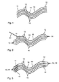
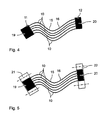
- FIGS. 1 to 5 show successive manufacturing steps for producing a flexible, thermal connecting element according to the invention.
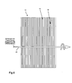
- Figure 6 shows a plan view of a CFK film or plate, which is used for the production of the connecting element according to the invention.
- thermal connections that allow the heat flow between different points of the spacecraft component. In this way, overheating or undercooling of structure and individual components can be avoided.
- Flexible thermal fasteners are made, for example, as multilayer strips of metal foils. These are flexible about an axis and have a sufficiently large cross-sectional area to ensure the heat transfer through the connecting element.
- the advantage of such fasteners is the ease of processing.
- a disadvantage is the relatively high specific gravity in relation to the conductivity.
- the connecting element 1 is bendable, so that it can be used well in space applications, such as space instruments or satellites, for heat transport. This allows the heat exchange between two components which are connected to one another via one or more connecting elements 1, realize relatively low loss.
- the structure of the connector 1 is based on the consideration that the thermal conductivity of a carbon fiber reinforced composite material is several times higher than that of copper or aluminum. At the same time, however, the weight of CFRP compared to metals is much lower.
- the connecting element 1 proposed according to the invention uses thermally highly conductive carbon fibers whose conductance in the fiber direction is three to four times as high as that of aluminum. This makes it possible to provide fasteners with low mass, high dimensional stability, good thermal conductivity and versatile uses.
- a connection element can be used not only in aerospace components, but generally in all such instruments, where a high dimensional stability in the foreground such as telescopic structures, optical banks, waveguides, antenna reflectors and structures, etc.
- the manufacture of the connecting element 1 is as follows. First, a number of CFRP layers 10 are provided. Each of the CFK layers 10 consists of a plurality of thermally conductive carbon fibers 15 which are embedded in a matrix material 16. Suitable carbon fibers are, for example, the carbon fibers Mitsubishi known under the name K13D2U. These have a thermal conductivity of about 800 W / mK in the fiber direction. Alternatively, the known under the name K1100 fibers could be used, which although has a much higher conductivity of 1100 W / mK, but is no longer produced and thus on the world market is no longer available. As the material of the matrix, a resin having a low rigidity and a high heat conductivity can be used. There are for example doped resin systems with carbon modifications such as carbon nanotubes, graphite or graphene into consideration.
- the carbon fibers 15 are unidirectional, i. aligned in one direction.
- the production of a CFRP layer is effected by impregnation with the material of the matrix in the fiber winding process with a plate tool.
- a carbon fiber roving can be wound on a core.
- the impregnation of the roving is carried out by means of resin application on the tool.
- the rovings are pressed with a tool lid to a tool core. About spacers, a defined layer thickness or a defined fiber volume content can be adjusted.
- a respective CFRP layer has a dimension of 100 x 150 mm with a thickness of ideally less than 0.15 mm.
- a total of five CFRP layers 10 are arranged one above the other in the embodiment.
- the carbon fibers 15 of a respective CFK layer 10 extend into Fig. 1 and in all other figures from a first end portion 11 to a second end portion 12.
- the flexibility of the ply package or stack present transversely to the fiber direction is visualized by the undulating course in the plane of the drawing.
- a next processing step the in Fig. 2 is shown, the respective end portions 11, 12 of all CFRP layers 10 are freed from the material of the matrix 16, so that the carbon fibers 15 of a respective CFRP layer in these sections 13, 14 are exposed.
- the exposure of the fiber ends of the matrix can be done by means of chemical dissolution (for example by means of hydrochloric acid solution) or thermal dissolution by means of laser beam.
- After removal of the matrix material about 60% of the layer thickness remains, with a fiber volume content of the untreated CFRP layer 10 of likewise 60%. Tests have shown that both chemical and thermal dissolution of the matrix material do not damage the carbon fibers.
- the dissolution of the matrix material 16 is schematically indicated by a laser beam 30 of the uppermost CFK layer 10.
- exposing the fiber ends of the carbon fibers of a respective CFRP layer could also be done prior to stacking the plurality of CFRP layers 10.
- the processing steps, in the Figures 1 and 2 are shown, also done in reverse order.
- a metallization of the exposed end sections 13, 14 takes place.
- first of all a galvanic copper plating of the exposed end sections 13, 14 of the carbon fibers 15 is carried out. It is sufficient if the layer thickness achieved in this case is up to about 20 microns.
- the end faces of the carbon fibers 15 are covered with the metal layer.
- a soldering of the pre-metallized fiber ends in this case, in a first intermediate step, first the metallized carbon fiber ends of a respective CFRP layer 10 can be thermally bonded to one another. It is expedient if the soldering of the metallized ends of the carbon fibers takes place over a plurality of CFRP layers 10. This results in the in Fig. 4 illustrated thermal connection 19 and 20 at the opposite end portions 11, 12 of the ply package.
- the connecting elements 21, 22 can be connected to the associated thermal connection 19, 20, for example, by a soldering, possibly combined with a clamping. Via the connecting elements 21, 22 is then a connection to the thermally and / or mechanically coupled to each other components, for example, a space instrument to make.
- a connecting element 1 produced in this way has a high performance at low density with mechanical flexibility of the component. This is realized through the use of carbon fibers with high heat transfer capability. A contamination problem due to fiber breakage in the production is minimized by the embedding of the carbon fibers in a matrix material or excluded. Characterized in that the end faces of the carbon fibers are in contact with the metallization, a loss-free entry or discharge of heat in or out of the fiber ends is made possible.
- Figure 6 shows a plan view of one of the CFK layers 10 in the form of a film or plate, from which the unidirectional course of the carbon fibers 15 in the matrix 16 emerges.
- the bending axis (reference numeral 23) is shown.
Landscapes
- Engineering & Computer Science (AREA)
- Mechanical Engineering (AREA)
- Physics & Mathematics (AREA)
- Thermal Sciences (AREA)
- General Engineering & Computer Science (AREA)
- Chemical & Material Sciences (AREA)
- Ceramic Engineering (AREA)
- Manufacture Of Alloys Or Alloy Compounds (AREA)
- Cooling Or The Like Of Semiconductors Or Solid State Devices (AREA)
- Laminated Bodies (AREA)
Abstract
Description
- Die Erfindung betrifft ein thermisches Verbindungselement, insbesondere für ein Raumfahrtinstrument, einen Satelliten, ein Verkehrsmittel oder ein Maschinenbauelement, sowie ein Verfahren zu dessen Herstellung.
- Thermische Verbindungselemente dienen der thermischen Kopplung zweier Komponenten zur Wärmeübertragung. Häufig sind die Verbindungselemente flexibel gestaltet, um eine Relativbewegung der miteinander durch das Verbindungselement verbundenen Komponenten zu erlauben.
- Der Wärmetransport über Feststoffe ist insbesondere bei Raumfahrtanwendungen, wie zum Beispiel einem Raumfahrtinstrument oder einem Satelliten von Bedeutung, da wegen des fehlenden Mediums Luft der Wärmetransport hauptsächlich über die Feststoffe, Strahlung oder Mehrphasensysteme erfolgen kann. Auch im Umfeld von Verkehrsmitteln, wie zum Beispiel Fahrzeugen, oder im Maschinenbau finden sich solche Anforderungen.
- Flexible, thermische Verbindungselemente werden in der Regel aus Metallen, wie zum Beispiel Kupfer oder Aluminium, realisiert. Dazu können beispielsweise mehrlagige Streifen aus Metallfolien hergestellt und miteinander verbunden werden, um eine Biegsamkeit um eine Achse bereitstellen zu können. Gleichzeitig wird eine ausreichend große Querschnittsfläche bereitgestellt, um den Wärmetransport durch ein solches Verbindungselement zu gewährleisten. Der Vorteil solcher Verbindungen liegt in der einfachen Verarbeitbarkeit von Metallen. Der Nachteil besteht in einem verhältnismäßig hohen spezifischen Gewicht im Verhältnis zur Leitfähigkeit. Während Kupfer im Vergleich zu Aluminium eine höhere Wärmeleitfähigkeit aufweist, ist gleichzeitig die Dichte größer. Ein sich hieraus ergebendes, höheres Gewicht ist insbesondere bei Raumfahrtanwendungen von Nachteil.
- Es sind ferner thermisch hoch leitende Kohlenstofffasern bekannt, deren Leitwerte in Faserrichtung bezüglich ihrer Wärmeleitfähigkeit drei- bis viermal so hoch wie von Aluminium sind. Solche Fasern können mehr Wärme bei deutlich weniger Gewicht transportieren. Allerdings ist die Herstellung eines thermischen, flexiblen Verbindungselements aufgrund der Sprödigkeit der einzelnen Kohlenstofffasern schwierig. Beispielsweise führt eine starke Klemmung der spröden Kohlenstofffasern, welche für eine gute Wärmeübertragung zwischen dem Verbindungselement und den mit dem Verbindungselement gekoppelten Komponenten erforderlich ist, zu einer starken Schädigung zumindest einzelner Kohlenstofffasern, so dass diese nicht mehr zu einer Wärmeleitung beitragen können. Da von einer Schädigung von Kohlenstofffasern zudem Verunreinigungen ausgehen können, welche vor allem bei Raumfahrtanwendungen problematisch sind, wurden aus Kohlenstofffasern bestehende Verbindungselemente bislang nicht zur Produktreife gebracht.
- Es ist Aufgabe der vorliegenden Erfindung, ein thermisches Verbindungselement anzugeben, dessen gewichtsspezifische Wärmeleitfähigkeit signifikant höher ist als bei einem Bauteil aus konventionellen Werkstoffen. Ferner soll ein Verfahren zur Herstellung eines solchen thermischen Verbindungselements angegeben werden.
- Diese Aufgaben werden gelöst durch ein thermisches Verbindungselement gemäß den Merkmalen des Patentanspruches 1 sowie ein Verfahren zur Herstellung gemäß den Merkmalen des Patentanspruches 13. Vorteilhafte Ausgestaltungen ergeben sich aus den abhängigen Patentansprüchen.
- Es wird ein thermisches Verbindungselement vorgeschlagen, das insbesondere für die Verwendung in einem Raumfahrtinstrument, einem Satelliten, einem Verkehrsmittel (wie zum Beispiel einem Kraftfahrzeug) oder einem Maschinenbauelement vorgesehen ist. Das Verbindungselement umfasst eine Anzahl an übereinander gestapelten kohlenstofffaserverstärkten Kunststofflagen (nachfolgend: CFK-Lagen), wobei jede der CFK-Lagen aus einer Mehrzahl an wärmeleitenden Kohlenstofffasern besteht, die in einer Matrix eingebettet sind. Die CFK-Lagen sind an zumindest zwei Abschnitten, insbesondere gegenüberliegenden Endabschnitten, von dem Material der Matrix befreit, so dass die Kohlenstofffasern einer jeweiligen CFK-Lage in den zumindest zwei Abschnitten freigelegt sind. Die freigelegten Abschnitte der Kohlenstofffasern sind mit einer zugeordneten Metallisierung versehen, über die das Verbindungselement mit einem thermisch leitenden Anschlusselement verbunden ist.
- Als Material der Matrix kann ein Harz verwendet werden, das eine möglichst geringe Steifigkeit und eine hohe Wärmeleitfähigkeit aufweist. Es kommen beispielsweise dotierte Harzsysteme mit Kohlenstoffmodifikationen wie Carbon-Nano-Tubes, Graphit oder Graphen in Betracht. Die CFK-Lagen sind beispielsweise platten- oder folienförmig ausgebildet.
- Ein solches thermisches Verbindungselement weist eine hohe Wärmeleitfähigkeit bei gleichzeitig geringer Dichte und mechanischer Flexibilität des Bauteils auf. Durch das Einbetten der Kohlenstofffasern in ein Matrixmaterial können bei einem Bruch von einzelnen der Kohlenstofffasern keine Verunreinigungen entstehen. Durch die Metallisierung und die thermisch leitenden Anschlusselemente, welche insbesondere aus einem herkömmlichen Metall bestehen, kann ein weitestgehend verlustfreier Eintrag bzw. Austrag von Wärme in das bzw. aus dem thermische(n) Verbindungselement und genauer in die bzw. an den Kohlenstofffasern der CFK-Lagen erfolgen. Durch die Metallisierung der freigelegten Abschnitte der Kohlenstofffasern ist eine gut wärmeleitende Verbindung mit einem jeweiligen thermisch leitenden Anschlusselement möglich.
- Gemäß einer zweckmäßigen Ausgestaltung sind die freigelegten Abschnitte der Kohlenstofffasern Endabschnitte der Kohlenstofffasern. Dabei erstrecken sich die Kohlenstofffasern unidirektional in einer Richtung von einem ersten der Endabschnitte zu einem zweiten der Endabschnitte. Die platten- bzw. folienartigen Elemente haben idealerweise eine Dicke von unter 0,15 mm. Hierdurch ergibt sich neben der guten thermischen Leitfähigkeit des Verbindungselements auch eine hohe Biegsamkeit des Verbindungselements um die Achse quer zur Faserrichtung.
- Gemäß einer weiteren Ausgestaltung weist die Dicke der freigelegten Abschnitte einer jeweiligen CFK-Lage zwischen 50 % und 70 %, insbesondere etwa 60 % der Dicke eines nicht freigelegten Abschnitts der jeweiligen CFK-Lage auf.
- Gemäß einer weiteren Ausgestaltung beträgt der Faservolumengehalt eines nicht freigelegten Abschnitts einer jeweiligen CFK-Lage zwischen 50 % und 70 %, insbesondere etwa 60 %. Dies bedeutet mit anderen Worten, dass das Verbindungselement im Bereich der freigelegten Abschnitte vollständig oder nahezu vollständig von dem Material der Matrix befreit ist.
- Die Metallisierung an den freigelegten Abschnitten weist gemäß einer weiteren zweckmäßigen Ausgestaltung eine Dicke von etwa 5 µm bis 20 µm auf. Durch das Vorsehen der Metallisierung an den freigelegten Abschnitten kann ein guter Wärmeanschluss zu den jeweiligen Anschlusselementen erzielt werden.
- Die Metallisierung ist gemäß einer zweckmäßigen Ausgestaltung aus Kupfer gebildet. Grundsätzlich sind jedoch auch andere, metallische Materialien, wie zum Beispiel Gold, Silber, und Legierungen davon, vorstellbar.
- Um einen besonders guten thermischen Übergang zwischen der Metallisierung und den Kohlenstofffasern der CFK-Lage(n) zu erzielen, ist es zweckmäßig, wenn die Metallisierung die einzelnen Kohlenstofffasern an den freigelegten Abschnitten umgibt. Ein weiter verbesserter Wärmeübergang ergibt sich dadurch, dass die mit der Metallisierung umgebenen Kohlenstofffasern zumindest einer CFK-Lage stoffschlüssig miteinander verbunden sind. Insbesondere kann das gesamte Lagenpaket stoffschlüssig im Bereich der Endabschnitte thermisch leitend miteinander verbunden sein.
- Für eine weiter optimierte Wärmeeinleitung in die Kohlenstofffasern ist es zweckmäßig, wenn die Metallisierung an Stirnflächen der von der Matrix freigelegten Kohlenstofffasern grenzt.
- Es ist bevorzugt, wenn die Kohlenstofffasern in Faserrichtung eine hohe Wärmeleitfähigkeit aufweisen. Beispielsweise kann ein unter dem Namen K13D2U bekanntes Kohlenstofffasermaterial der Firma Mitsubishi eingesetzt werden, welches mit ca. 800 W/mK eine der höchsten Wärmeleitfähigkeiten einer Kohlenstofffaser auf dem Weltmarkt aufweist.
- Es ist weiterhin zweckmäßig, wenn die Anschlusselemente jeweils stoffschlüssig mit den zugeordneten metallisierten Abschnitten verbunden sind. Bei dieser Ausgestaltung ergibt sich ein besonders guter Wärmeübergang von den Anschlusselementen auf die metallisierten, freigelegten Kohlenstofffasern. Im Fall einer rein kraftschlüssigen Verbindung, insbesondere durch Klemmung, können die Anschlusselemente zerstörungsfrei von dem mit der Metallisierung versehenen Lagenpaket gelöst werden.
- Es wird weiter ein Verfahren zur Herstellung eines thermischen Verbindungselements der oben beschriebenen Art vorgeschlagen. Dieses umfasst die folgenden Schritte:
- a) Bereitstellen einer Anzahl an CFK-Lagen, wobei jede der CFK-Lagen aus einer Mehrzahl an wärmeleitenden Kohlenstofffasern besteht, die in einer Matrix eingebettet sind;
- b) Entfernen des Materials der Matrix an zumindest zwei Abschnitten, insbesondere gegenüberliegenden Endabschnitten, jeder der Anzahl von CFK-Lagen, so dass die Kohlenstofffasern einer jeweiligen CFK-Lage in diesen Abschnitten freigelegt sind;
- c) Metallisieren der freigelegten Abschnitte;
- d) Stapeln der mit einer Metallisierung versehenen Abschnitte der Anzahl an CFK-Lagen zu einem Lagenpaket und Herstellen einer stoffschlüssigen Verbindung der metallisierten Abschnitte zumindest mancher der Anzahl an CFK-Lagen;
- e) Verbinden der metallisierten Abschnitte mit einem zugeordneten thermisch leitenden Anschlusselement.
- Insbesondere die Schritte b), c) und d) müssen nicht in der angegebenen Reihenfolge (b-c-d) durchgeführt werden, sondern können auch in einer davon abweichenden Reihenfolge ausgeführt werden. Beispielsweise können die Schritte c) und d) in ihrer Reihenfolge vertauscht werden. Ebenso kann Schritt d), gemäß dem das Stapeln der Anzahl an CFK-Lagen zu einem Lagenpaket erfolgt, bereits vor Schritt b durchgeführt werden.
- Das Entfernen des Materials der Matrix gemäß Schritt b) kann wahlweise durch chemisches Lösen oder durch thermisches Lösen erfolgen. Beim chemischen Lösen kann beispielsweise eine Salzsäurelösung verwendet werden, um die vorgegebenen Abschnitte, insbesondere Endabschnitte, einer jeweiligen CFK-Lage von dem Matrix-Material zu befreien. Ein thermisches Lösen kann beispielsweise mittels Laser erfolgen.
- Das Metallisieren der freigelegten Abschnitte gemäß Schritt c) erfolgt gemäß einer zweckmäßigen Ausgestaltung durch Galvanisieren, insbesondere mit Kupfer.
- Es ist zweckmäßig, wenn die stoffschlüssige Verbindung gemäß Schritt d) durch Löten hergestellt wird. Hierdurch können die metallisierten Abschnitte der Kohlenstofffasern einer jeweiligen Lage, aber auch von unterschiedlichen CFK-Lagen, zuverlässig miteinander verbunden werden. Darüber hinaus kann durch die Steuerung der Menge des auf- bzw. eingebrachten Lots ein sicherer Wärmeübergang zu dem thermisch leitenden Anschlusselement aufgrund der stark vergrößerten Kontaktfläche bzw. des thermisch aktiven Volumens sichergestellt werden.
- Gemäß einer weiteren Ausgestaltung des Verfahrens wird das, bevorzugt aus Metall bestehende, Anschlusselement mit dem zugeordneten metallisierten Endabschnitt durch Stoffschluss, insbesondere durch Löten, verbunden; eventuell kombiniert mit einer Verbindung durch Kraftschluss. Dadurch, dass der Kraftschluss zu einem, duktile Eigenschaften aufweisenden Lot erfolgt, kann die Gefahr der Beschädigung der Kohlenstofffasern aufgrund der durch das Anschlusselement eingeleiteten Kraft stark reduziert oder sogar vollständig eliminiert werden.
- Die Erzeugung der Anzahl an CFK-Lagen mit einer unidirektionalen Faserausrichtung der Kohlenstofffasern und die Tränkung mit einem Material der Matrix erfolgt gemäß einer weiteren zweckmäßigen Ausgestaltung bevorzugt im Faserwickelverfahren mit einem Wickelwerkzeug.
- Die Erfindung wird nachfolgend näher anhand eines Ausführungsbeispiels in der Zeichnung erläutert.
- Die
Figuren 1 bis 5 zeigen aufeinanderfolgende Herstellungsschritte zum Herstellen eines erfindungsgemäßen flexiblen, thermischen Verbindungselements.
Fig.6 zeigt eine Draufsicht auf eine CFK-Folie oder -platte, welche zur Herstellung des erfindungsgemäßen Verbindungselements verwendet wird. - Bei der thermalen Auslegung von Raumfahrtkomponenten, wie zum Beispiel Raumfahrtinstrumenten oder Satelliten, ist es erforderlich, thermische Verbindungen vorzusehen, die den Wärmefluss zwischen verschiedenen Punkten der Raumfahrtkomponente ermöglichen. Auf diese Weise können Überhitzungen oder Unterkühlungen von Struktur und Einzelkomponenten vermieden werden. Gegenwärtig werden solche thermische Verbindungen mit festen oder flexiblen Bauteilelementen gelöst, die aus konventionellen hoch wärmeleitfähigen Werkstoffen, wie Aluminium oder Kupfer, bestehen. Kupfer weist eine mehr als doppelt so hohe Wärmeleitfähigkeit als Aluminium auf, allerdings beträgt die Dichte von Kupfer mehr als das Dreifache der Dichte von Aluminium. Es ergibt sich insgesamt ein etwas besseres Verhältnis von Dichte zu Wärmeleitfähigkeit für Aluminium (ρ/αAlu = 17,3 kgK/Wm2 und ρ/αKupfer = 22,2 kgK/Wm2).
- Flexible thermische Verbindungselemente werden zum Beispiel als mehrlagige Streifen aus Metallfolien hergestellt. Diese sind um eine Achse biegsam und verfügen über eine ausreichend große Querschnittsfläche, um den Wärmetransport durch das Verbindungselement zu gewährleisten. Der Vorteil solcher Verbindungselemente liegt in der einfachen Verarbeitbarkeit. Ein Nachteil ist das relativ hohe spezifische Gewicht im Verhältnis zur Leitfähigkeit.
- Anhand der nachfolgenden Figuren wird die Herstellung eines erfindungsgemäßen flexiblen, thermischen Verbindungselements 1 mit im Vergleich zu herkömmlichen Verbindungselementen höherer gewichtsspezifischer Wärmeleitfähigkeit beschrieben. Gleichzeitig ist das Verbindungselement 1 biegeweich, so dass es sich in Raumfahrtanwendungen, wie zum Beispiel bei Raumfahrtinstrumenten oder Satelliten, gut zum Wärmetransport einsetzen lässt. Damit lässt sich der Wärmeaustausch zwischen zwei Komponenten, welche über ein oder mehrere Verbindungselemente 1 miteinander verbunden sind, verhältnismäßig verlustarm realisieren.
- Die Struktur des Verbindungselements 1 basiert auf der Überlegung, dass die Wärmeleitfähigkeit eines kohlefaserverstärkten Verbundwerkstoffs um ein mehrfaches höher als die von Kupfer oder Aluminium ist. Gleichzeitig ist jedoch das Gewicht von CFK gegenüber Metallen wesentlich geringer.
- Das erfindungsgemäß vorgeschlagene Verbindungselement 1 nutzt thermisch hoch leitende Kohlenstofffasern, deren Leitwerte in Faserrichtung drei- bis viermal so hoch wie das von Aluminium ist. Hierdurch lassen sich Verbindungselemente mit geringer Masse, hoher Formstabilität, guter thermischer Leitfähigkeit sowie vielseitigen Verwendungsmöglichkeiten bereitstellen. Ein solches Verbindungselement kann nicht nur in Raumfahrtkomponenten, sondern allgemein bei all solchen Instrumenten zum Einsatz kommen, wo eine hohe Formstabilität im Vordergrund steht, wie zum Beispiel bei Teleskopstrukturen, optischen Banken, Wellenleitern, Antennenreflektoren und -strukturen usw.
- Die Herstellung des Verbindungselements 1 ist wie folgt. Zunächst wird eine Anzahl an CFK-Lagen 10 bereitgestellt. Jede der CFK-Lagen 10 besteht aus einer Mehrzahl an wärmeleitenden Kohlenstofffasern 15, die in einem Matrixmaterial 16 eingebettet sind. Geeignete Kohlenstofffasern sind beispielsweise die unter dem Namen K13D2U bekannten Kohlenstofffasern der Firma Mitsubishi. Diese weisen in Faserrichtung eine Wärmeleitfähigkeit von ca. 800 W/mK auf. Alternativ könnten die unter dem Namen K1100 bekannten Fasern verwendet werden, welche zwar eine deutlich höhere Leitfähigkeit von 1100 W/mK aufweist, allerdings nicht mehr produziert wird und somit auf dem Weltmarkt nicht mehr verfügbar ist. Als Material der Matrix kann ein Harz verwendet werden, das eine geringe Steifigkeit und eine hohe Wärmeleitfähigkeit aufweist. Es kommen beispielsweise dotierte Harzsysteme mit Kohlenstoffmodifikationen wie Carbon-Nano-Tubes, Graphit oder Graphen in Betracht.
- In jeder der CFK-Lagen 10 sind die Kohlenstofffasern 15 unidirektional, d.h. in einer Richtung ausgerichtet. Die Erzeugung einer CFK-Lage erfolgt durch Tränkung mit dem Material der Matrix im Faserwickelverfahren mit einem Plattenwerkzeug. Hierzu kann im Rahmen des Herstellungsprozesses ein Kohlenstofffaser-Roving auf einen Kern gewickelt werden. Die Tränkung des Rovings wird mittels Harzauftrag am Werkzeug durchgeführt. Nach der Wicklung werden die Rovings mit einem Werkzeugdeckel an einen Werkzeugkern gepresst. Über Abstandsstücke kann eine definierte Schichtdicke bzw. ein definierter Faservolumengehalt eingestellt werden.
- Eine jeweilige CFK-Lage hat beispielsweise eine Abmessung von 100 x 150 mm bei einer Dicke von idealerweise unter 0,15 mm.
- Durch eine Minimierung der Faseranzahl in Dickenrichtung einer jeweiligen Platte kann eine höhere Biegsamkeit um die Achse quer zur Faserrichtung erzielt werden. Dies kann durch eine Aufspreizung des Faser-Rovings im Rahmen der Verarbeitung erreicht werden. Auch eine Änderung des Faserwinkels zur Wärmeflussrichtung hat eine Verringerung der Biegesteifigkeit um die Querachse zur Wärmeflussrichtung zur Folge. Eine Kombination dieser Ansätze ist möglich.
- Wie aus
Fig. 1 ersichtlich ist, werden im Ausführungsbeispiel insgesamt fünf CFK-Lagen 10 übereinander angeordnet. Die Kohlenstofffasern 15 einer jeweiligen CFK-Lage 10 erstrecken sich inFig. 1 sowie in allen anderen Figuren von einem ersten Endabschnitt 11 zu einem zweiten Endabschnitt 12. Lediglich zu Illustrationszwecken ist die quer zur Faserrichtung vorhandene Biegsamkeit des Lagenpakets bzw. -Stapels durch den wellenförmigen Verlauf in der Ebene der Zeichnung visualisiert. - In einem nächsten Verarbeitungsschritt, der in
Fig. 2 dargestellt ist, werden die jeweiligen Endabschnitte 11, 12 sämtlicher CFK-Lagen 10 vom Material der Matrix 16 befreit, so dass die Kohlenstofffasern 15 einer jeweiligen CFK-Lage in diesen Abschnitten 13, 14 freigelegt sind. Das Freilegen der Faserenden von der Matrix kann mittels chemischen Lösens (zum Beispiel mittels Salzsäurelösung) oder thermischen Lösens mittels Laserstrahl erfolgen. Nach dem Entfernen des Matrix-Materials verbleiben etwa 60 % der Schichtdicke erhalten, bei einem Faservolumengehalt der unbehandelten CFK-Lage 10 von ebenfalls 60 %. Anhand von Versuchen konnte festgestellt werden, dass sowohl durch chemisches als auch thermisches Lösen des Matrix-Materials keine Schädigungen an den Kohlenstofffasern entstehen. InFig. 3 ist das Lösen des Matrix-Materials 16 schematisch durch einen Laserstrahl 30 der obersten CFK-Lage 10 angedeutet. - Im Gegensatz zur vorangehenden Beschreibung könnte das Freilegen der Faserenden der Kohlenstofffasern einer jeweiligen CFK-Lage auch vor dem Stapeln der Mehrzahl an CFK-Lagen 10 erfolgen. Mit anderen Worten könnten die Verarbeitungsschritte, die in den
Figuren 1 und 2 dargestellt sind, auch in umgekehrter Reihenfolge erfolgen. - In einem nächsten Schritt (
Fig. 3 ) erfolgt ein Metallisieren der freigelegten Endabschnitte 13, 14. Hierzu wird zunächst eine galvanische Verkupferung der freigelegten Endabschnitten 13, 14 der Kohlenstofffasern 15 durchgeführt. Es ist ausreichend, wenn die hierbei erzielte Schichtdicke bis etwa 20 µm beträgt. Insbesondere werden bei der Galvanisierung auch die Stirnflächen der Kohlenstofffasern 15 mit der Metallschicht bedeckt. Anschließend erfolgt ein Verlöten der vormetallisierten Faserenden. Dabei können in einem ersten Zwischenschritt zunächst die metallisierten Kohlenstofffaserenden einer jeweiligen CFK-Lage 10 thermisch miteinander verbunden werden. Es ist zweckmäßig, wenn die Verlötung der metallisierten Enden der Kohlenstofffasern über mehrere CFK-Lagen 10 hinweg erfolgt. Hieraus ergibt sich die inFig. 4 dargestellte thermische Verbindung 19 bzw. 20 an den gegenüberliegenden Endabschnitten 11, 12 des Lagenpakets. - Schließlich wird in einem letzten Verarbeitungsschritt ein jeweiliges metallisches, da gut wärmeleitendes Anschlusselement 21, 22 mit den wie oben beschriebenen erzeugten, thermischen Verbindungen 19, 20 durch Stoffschluss ggf. kombiniert mit Kraftschluss, miteinander verbunden. Die Anschlusselemente 21, 22 können mit der zugeordneten thermischen Verbindung 19, 20 beispielsweise durch eine Lötung, ggf. kombiniert mit einer Klemmung, verbunden werden. Über die Anschlusselemente 21, 22 ist dann eine Verbindung zu den thermisch und/oder mechanisch miteinander zu koppelnden Komponenten, zum Beispiel eines Raumfahrtinstruments, vorzunehmen.
- Ein derart hergestelltes Verbindungselement 1 weist eine hohe Leistungsfähigkeit zu geringe Dichte bei mechanischer Flexibilität des Bauteils auf. Dies wird durch die Verwendung von Kohlenstofffasern mit hoher Wärmeübertragungsfähigkeit realisiert. Ein Verunreinigungsproblem durch Faserbruch im Rahmen der Herstellung ist durch die Einbettung der Kohlenstofffasern in ein Matrix-Material minimiert bzw. ausgeschlossen. Dadurch, dass die Stirnflächen der Kohlenstofffasern mit der Metallisierung in Kontakt stehen, wird ein verlustfreier Eintrag bzw. Austrag von Wärme in bzw. aus den Faserenden ermöglicht.
-
Fig.6 zeigt eine Draufsicht auf eine der CFK-Lagen 10 in Gestalt einer Folie oder Platte, aus der der unidirektionale Verlauf der Kohlenstofffasern 15 in der Matrix 16 hervorgeht. Zusätzlich ist die Biegeachse (Bezugszeichen 23) dargestellt. -
- 1
- Verbindungselement
- 10
- CFK-Lage
- 11
- erster (End)abschnitt der CFK-Lage 10
- 12
- zweiter (End)abschnitt der CFK-Lage 10
- 13
- erster, freigelegter Endabschnitt der CFK-Lage 10
- 14
- zweiter, freigelegter Endabschnitt der CFK-Lage 10
- 15
- Kohlenstofffasern
- 16
- Matrix
- 17
- Metallisierung in dem von der Matrix freigelegten ersten Endabschnitt 13
- 18
- Metallisierung in dem von der Matrix freigelegten zweiten Endabschnitt 14
- 19
- thermische Verbindung
- 20
- thermische Verbindung
- 21
- erstes Anschlusselement
- 22
- zweites Anschlusselement
- 23
- Biegeachse
- 30
- Laserstrahl
Claims (18)
- Thermisches Verbindungselement (1), insbesondere für ein Raumfahrtinstrument, einen Satelliten, ein Verkehrsmittel oder ein Maschinenbauelement, bei dem- eine Anzahl an übereinander gestapelten CFK-Lagen (10) vorgesehen ist, wobei jede der CFK-Lagen aus einer Mehrzahl an wärmeleitenden Kohlenstofffasern (15) besteht, die in einer Matrix (16) eingebettet sind;- die CFK-Lagen (10) an zumindest zwei Abschnitten (11, 12), insbesondere gegenüberliegenden Endabschnitten, von dem Material der Matrix (16) befreit sind, so dass die Kohlenstofffasern (15) einer jeweiligen CFK-Lage (10) in den zumindest zwei Abschnitten (11, 12) freigelegt sind;- die freigelegten Abschnitte (13, 14) der Kohlenstofffasern (15) mit einer zugeordneten Metallisierung (17, 18) versehen sind, über die das Verbindungselement (1) mit einem thermisch leitenden Anschlusselement (21, 22) verbunden ist.
- Verbindungselement nach Anspruch 1, bei dem die freigelegten Abschnitte (13, 14) der Kohlenstofffasern (15) Endabschnitte der Kohlenstofffasern (15) sind, wobei sich die Kohlenstofffasern (15) unidirektional in einer Richtung von einem ersten der Endabschnitte (13) zu einem zweiten der Endabschnitte (14) erstrecken.
- Verbindungselement nach Anspruch 1 oder 2, bei dem die CFK-Lagen (10)eine Dicke von unter 0,15 mm aufweisen.
- Verbindungselement nach einem der vorhergehenden Ansprüche, bei dem die Dicke der freigelegten Abschnitte (13, 14) einer jeweiligen CFK-Lage (10) zwischen 50 % und 70 %, insbesondere etwa 60 %, der Dicke eines nicht freigelegten Abschnitts der jeweiligen CFK-Lage (10) beträgt.
- Verbindungselement nach einem der vorhergehenden Ansprüche, bei dem der Faservolumengehalt eines nicht freigelegten Abschnitts einer jeweiligen CFK-Lage (10) zwischen 50 % und 70 %, insbesondere etwa 60 %, beträgt.
- Verbindungselement nach einem der vorhergehenden Ansprüche, bei dem die Metallisierung an den freigelegten Abschnitten (13, 14) eine Dicke von etwa 5 µm bis 20 µm aufweist.
- Verbindungselement nach einem der vorhergehenden Ansprüche, bei dem die Metallisierung (17, 18) aus Kupfer gebildet ist.
- Verbindungselement nach einem der vorhergehenden Ansprüche, bei dem die Metallisierung (17, 18) die einzelnen Kohlenstofffasern (15) an den freigelegten Abschnitten (13, 14) umgibt.
- Verbindungselement nach Anspruch 8, bei dem die mit der Metallisierung (17, 18) umgebenen Kohlenstofffasern (15) zumindest einer CFK-Lage (10) stoffschlüssig miteinander verbunden sind.
- Verbindungselement nach einem der vorhergehenden Ansprüche, bei dem die Metallisierung (17, 18) an Stirnflächen der von der Matrix (16) freigelegten Kohlenstofffasern (15) grenzt.
- Verbindungselement nach einem der vorhergehenden Ansprüche, bei dem die Kohlenstofffasern (15) in Faserrichtung eine Wärmeleitfähigkeit von mindestens etwa 800 W/mK, aufweisen.
- Verbindungselement nach einem der vorhergehenden Ansprüche, bei dem die Anschlusselemente (21, 22) jeweils stoffschlüssig, insbesondere durch Lötung und optional kombiniert mit einer kraftschlüssigen Verbindung, insbesondere durch Klemmung, mit den zugeordneten metallisierten Abschnitten (13, 14) verbunden sind.
- Verfahren zur Herstellung eines thermischen Verbindungselements (1), das gemäß einem der vorhergehenden Ansprüche ausgebildet ist, mit den folgenden Schritten:a) Bereitstellen einer Anzahl an CFK-Lagen (10), wobei jede der CFK-Lagen aus einer Mehrzahl an wärmeleitenden Kohlenstofffasern (15) besteht, die in einer Matrix (16) eingebettet sind;b) Entfernen des Materials der Matrix (16) an zumindest zwei Abschnitten (11, 12), insbesondere gegenüberliegenden Endabschnitten, jeder der Anzahl von CFK-Lagen (10), so dass die Kohlenstofffasern (15) einer jeweiligen CFK-Lage (10) in diesen Abschnitten freigelegt sind;c) Metallisieren der freigelegten Abschnitte (13, 14);d) Stapeln der mit einer Metallisierung (17, 18) versehenen Abschnitte (13, 14) der Anzahl an CFK-Lagen (10) zu einem Lagenpaket und Herstellen einer stoffschlüssigen Verbindung der metallisierten Abschnitte (13, 14) zumindest mancher der Anzahl an CFK-Lagen (10);e) Verbinden der metallisierten Abschnitte (13, 14) mit einem zugeordneten thermisch leitenden Anschlusselement (21, 22).
- Verfahren nach Anspruch 13, bei dem das Entfernen des Materials der Matrix (16) gemäß Schritt b) durch chemisches Lösen oder durch thermisches Lösen erfolgt.
- Verfahren nach Anspruch 13 oder 14, bei dem das Metallisieren der freigelegten Abschnitte (13, 14) gemäß Schritt c) durch Galvanisieren, insbesondere mit Kupfer, erfolgt.
- Verfahren nach einem der Ansprüche 13 bis 15, bei dem die stoffschlüssige Verbindung gemäß Schritt d) durch Löten hergestellt wird.
- Verfahren nach einem der Ansprüche 13 bis 16, bei dem das Anschlusselement (21, 22) mit dem zugeordneten metallisierten Endabschnitt (13, 14) durch Stoffschluss, insbesondere durch Löten, optional in Kombination mit Kraftschluss, insbesondere durch Klemmen, verbunden wird.
- Verfahren nach einem der Ansprüche 13 bis 17, bei dem die Erzeugung der Anzahl an CFK-Lagen (10) mit einer unidirektionalen Faserausrichtung der Kohlenstofffasern (15) und die Tränkung mit einem Material der Matrix (16) im Faserwickelverfahren mit einem Wickelwerkzeug erfolgt.
Applications Claiming Priority (1)
| Application Number | Priority Date | Filing Date | Title |
|---|---|---|---|
| DE102014000908.4A DE102014000908A1 (de) | 2014-01-28 | 2014-01-28 | Thermisches Verbindungselement und Verfahren zu dessen Herstellung |
Publications (2)
| Publication Number | Publication Date |
|---|---|
| EP2899019A1 true EP2899019A1 (de) | 2015-07-29 |
| EP2899019B1 EP2899019B1 (de) | 2018-04-25 |
Family
ID=52462780
Family Applications (1)
| Application Number | Title | Priority Date | Filing Date |
|---|---|---|---|
| EP15000172.5A Active EP2899019B1 (de) | 2014-01-28 | 2015-01-22 | Thermisches verbindungselement und verfahren zu dessen herstellung |
Country Status (3)
| Country | Link |
|---|---|
| US (1) | US10345054B2 (de) |
| EP (1) | EP2899019B1 (de) |
| DE (1) | DE102014000908A1 (de) |
Families Citing this family (9)
| Publication number | Priority date | Publication date | Assignee | Title |
|---|---|---|---|---|
| DE102017116033B4 (de) * | 2017-07-17 | 2021-08-26 | Deutsches Zentrum für Luft- und Raumfahrt e.V. | Verfahren zur Herstellung eines Faserhalbzeuges und eines Faserverbundbauteils sowie Faserverbundbauteil |
| EP3733527B1 (de) | 2017-12-29 | 2022-08-17 | Airbus Defence and Space SA | Thermischer verbinder mit hoher leitfähigkeit |
| US11931998B2 (en) | 2018-07-02 | 2024-03-19 | Rasei Limited | Moveable and wearable items, and systems and methods for monitoring or controlling such items |
| GB2571148B (en) * | 2018-07-02 | 2021-02-10 | Rasei Ltd | Movable items and wearable items worn by users of the same, and systems and methods for monitoring or controlling operation of movable items |
| US11248852B2 (en) * | 2020-07-06 | 2022-02-15 | Dell Products L.P. | Graphite thermal cable and method for implementing same |
| TWM603524U (zh) * | 2020-07-27 | 2020-11-01 | 華碩電腦股份有限公司 | 導熱裝置 |
| CN113412026B (zh) * | 2021-04-30 | 2022-11-25 | 北京化工大学 | 一种轻质柔性碳纤维/金属复合导热索的制备方法 |
| US12328845B2 (en) * | 2021-12-20 | 2025-06-10 | Meta Platforms Technologies, Llc | Thermal conduit for electronic device |
| IT202200012077A1 (it) | 2022-06-08 | 2023-12-08 | Weart S R L | Dispositivo aptico per l'applicazione di stimoli sensoriali |
Citations (2)
| Publication number | Priority date | Publication date | Assignee | Title |
|---|---|---|---|---|
| US4849858A (en) * | 1986-10-20 | 1989-07-18 | Westinghouse Electric Corp. | Composite heat transfer means |
| JP2001110952A (ja) * | 1999-10-04 | 2001-04-20 | Fujikura Rubber Ltd | 放熱装置 |
Family Cites Families (9)
| Publication number | Priority date | Publication date | Assignee | Title |
|---|---|---|---|---|
| US5390734A (en) * | 1993-05-28 | 1995-02-21 | Lytron Incorporated | Heat sink |
| JPH09262917A (ja) * | 1996-03-28 | 1997-10-07 | Mitsubishi Electric Corp | 伝熱素子 |
| US6060166A (en) * | 1998-02-05 | 2000-05-09 | Raytheon Company | Flexible graphite fiber thermal shunt |
| US5949650A (en) * | 1998-09-02 | 1999-09-07 | Hughes Electronics Corporation | Composite heat sink/support structure |
| US6246012B1 (en) * | 1999-03-24 | 2001-06-12 | Xerox Corporation | Electroplated conductive carbon fibers with adhesive |
| US7220131B1 (en) * | 2005-12-20 | 2007-05-22 | Xerox Corporation | Electromechanical device having a plurality of bundles of fibers for interconnecting two planar surfaces |
| JP2008205041A (ja) * | 2007-02-16 | 2008-09-04 | Toshiba Corp | 電子機器および熱伝導部材 |
| CN101346054B (zh) * | 2007-07-13 | 2010-05-26 | 清华大学 | 热界面材料、其制备方法及具有该热界面材料的封装体 |
| DE102011004801B4 (de) * | 2011-02-25 | 2013-11-07 | Fraunhofer-Gesellschaft zur Förderung der angewandten Forschung e.V. | Selektiv beschichtete CFK-Bauteile und Verfahren zu deren Herstellung |
-
2014
- 2014-01-28 DE DE102014000908.4A patent/DE102014000908A1/de not_active Ceased
-
2015
- 2015-01-22 EP EP15000172.5A patent/EP2899019B1/de active Active
- 2015-01-27 US US14/606,081 patent/US10345054B2/en active Active
Patent Citations (2)
| Publication number | Priority date | Publication date | Assignee | Title |
|---|---|---|---|---|
| US4849858A (en) * | 1986-10-20 | 1989-07-18 | Westinghouse Electric Corp. | Composite heat transfer means |
| JP2001110952A (ja) * | 1999-10-04 | 2001-04-20 | Fujikura Rubber Ltd | 放熱装置 |
Also Published As
| Publication number | Publication date |
|---|---|
| US20150211815A1 (en) | 2015-07-30 |
| US10345054B2 (en) | 2019-07-09 |
| EP2899019B1 (de) | 2018-04-25 |
| DE102014000908A1 (de) | 2015-07-30 |
Similar Documents
| Publication | Publication Date | Title |
|---|---|---|
| EP2899019B1 (de) | Thermisches verbindungselement und verfahren zu dessen herstellung | |
| DE3204231C2 (de) | Laminat mit einem Metall-Faser-Verbundmaterial und dessen Verwendung | |
| DE10066446B4 (de) | Verfahren zur Herstellung eines elektronischen Bauteils mit zwei Abstrahlungsbauteilen | |
| EP2509772B1 (de) | Verfahren zum anbinden eines faserverbundbauteils an ein strukturbauteil eines luft- und raumfahrzeuges und eine entsprechende anordnung | |
| DE69431909T2 (de) | Ein verstärktes verbindungselement von verbundstrukturen und verfahren zum verbinden von verbundteilen | |
| EP1746077A1 (de) | Metallbeschichtete Graphitfolie | |
| DE2824250C2 (de) | Trägerelektrode eines Halbleiterbauelements | |
| DE602004008685T2 (de) | Verbundwerkstoff und Verfahren zur Herstellung desselben | |
| DE112020002412T5 (de) | Übergang von metallischen gittern zum verbinden von faserverstärkten polymeren und metallischen strukturen | |
| DE112018005786T5 (de) | Plattiertes Material und Verfahren zu dessen Herstellung | |
| DE112017002505B4 (de) | Faservertärkter Schichtstoff, Verschlussvorrichtung und optisches Gerät | |
| DE102017119491A1 (de) | Verfahren und Vorrichtung zum Verschweißen von einem Duromer-Objekt mit einem weiteren Objekt über thermoplastische äußere Schichten | |
| DE69501768T2 (de) | Haltevorrichtung für Batterien | |
| DE102021120219A1 (de) | Batterieanordnung, Multifunktionsschicht und Verfahren zum Herstellen einer Batterieanordnung | |
| DE102020107240A1 (de) | Kompositverbindung zweier Bauteile | |
| EP1401636A2 (de) | Trennblech bzw. verfahren zur herstellung eines trennbleches für ein multilayerpresspaket | |
| WO2004030429A1 (de) | Verfahren zur herstellung von starr-flexiblen leiterplatten und leiterplatte mit mindestens einem starren bereich und mindestens einem flexiblen bereich | |
| DE102014103954A1 (de) | Verstärkungsstrukturen mit wärmeleitfähigkeitserhöhender Beschichtung in Harzmatrix und von Beschichtung getrennte elektrische Leiterstruktur | |
| WO2022053267A1 (de) | Kühlanordnung sowie batterieanordnung mit einem elastischen element zum beaufschlagen eines wärmeleitmediums mit einer kraft | |
| DE102013219404A1 (de) | Verfahren zur Herstellung von Bändern und Streifen aus zwei metallischen Materialien | |
| DE102024114273A1 (de) | Kern mit integriertem graphen und zugehörige verfahren für das wärmemanagement in leiterplatten | |
| DE102010042294A1 (de) | Verfahren zum Herstellen eines Verbundwerkstoffs und Verbundwerkstoff | |
| DE102024001023A1 (de) | Verfahren zur Herstellung einer Verbundanordnung und Verbundanordnung | |
| EP4403339A1 (de) | Verfahren zur herstellung eines hybridbauteils | |
| DE102014018304A1 (de) | Zellblock mit einem Zellstapel |
Legal Events
| Date | Code | Title | Description |
|---|---|---|---|
| PUAI | Public reference made under article 153(3) epc to a published international application that has entered the european phase |
Free format text: ORIGINAL CODE: 0009012 |
|
| 17P | Request for examination filed |
Effective date: 20150122 |
|
| AK | Designated contracting states |
Kind code of ref document: A1 Designated state(s): AL AT BE BG CH CY CZ DE DK EE ES FI FR GB GR HR HU IE IS IT LI LT LU LV MC MK MT NL NO PL PT RO RS SE SI SK SM TR |
|
| AX | Request for extension of the european patent |
Extension state: BA ME |
|
| 17P | Request for examination filed |
Effective date: 20151211 |
|
| RBV | Designated contracting states (corrected) |
Designated state(s): AL AT BE BG CH CY CZ DE DK EE ES FI FR GB GR HR HU IE IS IT LI LT LU LV MC MK MT NL NO PL PT RO RS SE SI SK SM TR |
|
| STAA | Information on the status of an ep patent application or granted ep patent |
Free format text: STATUS: EXAMINATION IS IN PROGRESS |
|
| 17Q | First examination report despatched |
Effective date: 20170724 |
|
| GRAP | Despatch of communication of intention to grant a patent |
Free format text: ORIGINAL CODE: EPIDOSNIGR1 |
|
| STAA | Information on the status of an ep patent application or granted ep patent |
Free format text: STATUS: GRANT OF PATENT IS INTENDED |
|
| INTG | Intention to grant announced |
Effective date: 20171122 |
|
| RAP1 | Party data changed (applicant data changed or rights of an application transferred) |
Owner name: AIRBUS DEFENCE AND SPACE GMBH |
|
| GRAA | (expected) grant |
Free format text: ORIGINAL CODE: 0009210 |
|
| GRAS | Grant fee paid |
Free format text: ORIGINAL CODE: EPIDOSNIGR3 |
|
| STAA | Information on the status of an ep patent application or granted ep patent |
Free format text: STATUS: THE PATENT HAS BEEN GRANTED |
|
| AK | Designated contracting states |
Kind code of ref document: B1 Designated state(s): AL AT BE BG CH CY CZ DE DK EE ES FI FR GB GR HR HU IE IS IT LI LT LU LV MC MK MT NL NO PL PT RO RS SE SI SK SM TR |
|
| REG | Reference to a national code |
Ref country code: GB Ref legal event code: FG4D Free format text: NOT ENGLISH |
|
| REG | Reference to a national code |
Ref country code: CH Ref legal event code: EP |
|
| REG | Reference to a national code |
Ref country code: AT Ref legal event code: REF Ref document number: 992430 Country of ref document: AT Kind code of ref document: T Effective date: 20180515 |
|
| REG | Reference to a national code |
Ref country code: IE Ref legal event code: FG4D Free format text: LANGUAGE OF EP DOCUMENT: GERMAN |
|
| REG | Reference to a national code |
Ref country code: DE Ref legal event code: R096 Ref document number: 502015003965 Country of ref document: DE |
|
| REG | Reference to a national code |
Ref country code: NL Ref legal event code: MP Effective date: 20180425 |
|
| REG | Reference to a national code |
Ref country code: LT Ref legal event code: MG4D |
|
| PG25 | Lapsed in a contracting state [announced via postgrant information from national office to epo] |
Ref country code: NL Free format text: LAPSE BECAUSE OF FAILURE TO SUBMIT A TRANSLATION OF THE DESCRIPTION OR TO PAY THE FEE WITHIN THE PRESCRIBED TIME-LIMIT Effective date: 20180425 |
|
| PG25 | Lapsed in a contracting state [announced via postgrant information from national office to epo] |
Ref country code: FI Free format text: LAPSE BECAUSE OF FAILURE TO SUBMIT A TRANSLATION OF THE DESCRIPTION OR TO PAY THE FEE WITHIN THE PRESCRIBED TIME-LIMIT Effective date: 20180425 Ref country code: NO Free format text: LAPSE BECAUSE OF FAILURE TO SUBMIT A TRANSLATION OF THE DESCRIPTION OR TO PAY THE FEE WITHIN THE PRESCRIBED TIME-LIMIT Effective date: 20180725 Ref country code: BG Free format text: LAPSE BECAUSE OF FAILURE TO SUBMIT A TRANSLATION OF THE DESCRIPTION OR TO PAY THE FEE WITHIN THE PRESCRIBED TIME-LIMIT Effective date: 20180725 Ref country code: PL Free format text: LAPSE BECAUSE OF FAILURE TO SUBMIT A TRANSLATION OF THE DESCRIPTION OR TO PAY THE FEE WITHIN THE PRESCRIBED TIME-LIMIT Effective date: 20180425 Ref country code: SE Free format text: LAPSE BECAUSE OF FAILURE TO SUBMIT A TRANSLATION OF THE DESCRIPTION OR TO PAY THE FEE WITHIN THE PRESCRIBED TIME-LIMIT Effective date: 20180425 Ref country code: ES Free format text: LAPSE BECAUSE OF FAILURE TO SUBMIT A TRANSLATION OF THE DESCRIPTION OR TO PAY THE FEE WITHIN THE PRESCRIBED TIME-LIMIT Effective date: 20180425 Ref country code: LT Free format text: LAPSE BECAUSE OF FAILURE TO SUBMIT A TRANSLATION OF THE DESCRIPTION OR TO PAY THE FEE WITHIN THE PRESCRIBED TIME-LIMIT Effective date: 20180425 |
|
| PG25 | Lapsed in a contracting state [announced via postgrant information from national office to epo] |
Ref country code: LV Free format text: LAPSE BECAUSE OF FAILURE TO SUBMIT A TRANSLATION OF THE DESCRIPTION OR TO PAY THE FEE WITHIN THE PRESCRIBED TIME-LIMIT Effective date: 20180425 Ref country code: HR Free format text: LAPSE BECAUSE OF FAILURE TO SUBMIT A TRANSLATION OF THE DESCRIPTION OR TO PAY THE FEE WITHIN THE PRESCRIBED TIME-LIMIT Effective date: 20180425 Ref country code: GR Free format text: LAPSE BECAUSE OF FAILURE TO SUBMIT A TRANSLATION OF THE DESCRIPTION OR TO PAY THE FEE WITHIN THE PRESCRIBED TIME-LIMIT Effective date: 20180726 Ref country code: RS Free format text: LAPSE BECAUSE OF FAILURE TO SUBMIT A TRANSLATION OF THE DESCRIPTION OR TO PAY THE FEE WITHIN THE PRESCRIBED TIME-LIMIT Effective date: 20180425 |
|
| PG25 | Lapsed in a contracting state [announced via postgrant information from national office to epo] |
Ref country code: PT Free format text: LAPSE BECAUSE OF FAILURE TO SUBMIT A TRANSLATION OF THE DESCRIPTION OR TO PAY THE FEE WITHIN THE PRESCRIBED TIME-LIMIT Effective date: 20180827 |
|
| REG | Reference to a national code |
Ref country code: DE Ref legal event code: R097 Ref document number: 502015003965 Country of ref document: DE |
|
| PG25 | Lapsed in a contracting state [announced via postgrant information from national office to epo] |
Ref country code: DK Free format text: LAPSE BECAUSE OF FAILURE TO SUBMIT A TRANSLATION OF THE DESCRIPTION OR TO PAY THE FEE WITHIN THE PRESCRIBED TIME-LIMIT Effective date: 20180425 Ref country code: EE Free format text: LAPSE BECAUSE OF FAILURE TO SUBMIT A TRANSLATION OF THE DESCRIPTION OR TO PAY THE FEE WITHIN THE PRESCRIBED TIME-LIMIT Effective date: 20180425 Ref country code: RO Free format text: LAPSE BECAUSE OF FAILURE TO SUBMIT A TRANSLATION OF THE DESCRIPTION OR TO PAY THE FEE WITHIN THE PRESCRIBED TIME-LIMIT Effective date: 20180425 Ref country code: CZ Free format text: LAPSE BECAUSE OF FAILURE TO SUBMIT A TRANSLATION OF THE DESCRIPTION OR TO PAY THE FEE WITHIN THE PRESCRIBED TIME-LIMIT Effective date: 20180425 Ref country code: SK Free format text: LAPSE BECAUSE OF FAILURE TO SUBMIT A TRANSLATION OF THE DESCRIPTION OR TO PAY THE FEE WITHIN THE PRESCRIBED TIME-LIMIT Effective date: 20180425 |
|
| PG25 | Lapsed in a contracting state [announced via postgrant information from national office to epo] |
Ref country code: SM Free format text: LAPSE BECAUSE OF FAILURE TO SUBMIT A TRANSLATION OF THE DESCRIPTION OR TO PAY THE FEE WITHIN THE PRESCRIBED TIME-LIMIT Effective date: 20180425 Ref country code: IT Free format text: LAPSE BECAUSE OF FAILURE TO SUBMIT A TRANSLATION OF THE DESCRIPTION OR TO PAY THE FEE WITHIN THE PRESCRIBED TIME-LIMIT Effective date: 20180425 |
|
| PLBE | No opposition filed within time limit |
Free format text: ORIGINAL CODE: 0009261 |
|
| STAA | Information on the status of an ep patent application or granted ep patent |
Free format text: STATUS: NO OPPOSITION FILED WITHIN TIME LIMIT |
|
| 26N | No opposition filed |
Effective date: 20190128 |
|
| PG25 | Lapsed in a contracting state [announced via postgrant information from national office to epo] |
Ref country code: SI Free format text: LAPSE BECAUSE OF FAILURE TO SUBMIT A TRANSLATION OF THE DESCRIPTION OR TO PAY THE FEE WITHIN THE PRESCRIBED TIME-LIMIT Effective date: 20180425 |
|
| PG25 | Lapsed in a contracting state [announced via postgrant information from national office to epo] |
Ref country code: MC Free format text: LAPSE BECAUSE OF FAILURE TO SUBMIT A TRANSLATION OF THE DESCRIPTION OR TO PAY THE FEE WITHIN THE PRESCRIBED TIME-LIMIT Effective date: 20180425 |
|
| REG | Reference to a national code |
Ref country code: CH Ref legal event code: PL |
|
| PG25 | Lapsed in a contracting state [announced via postgrant information from national office to epo] |
Ref country code: LU Free format text: LAPSE BECAUSE OF NON-PAYMENT OF DUE FEES Effective date: 20190122 |
|
| REG | Reference to a national code |
Ref country code: BE Ref legal event code: MM Effective date: 20190131 |
|
| REG | Reference to a national code |
Ref country code: IE Ref legal event code: MM4A |
|
| PG25 | Lapsed in a contracting state [announced via postgrant information from national office to epo] |
Ref country code: BE Free format text: LAPSE BECAUSE OF NON-PAYMENT OF DUE FEES Effective date: 20190131 Ref country code: AL Free format text: LAPSE BECAUSE OF FAILURE TO SUBMIT A TRANSLATION OF THE DESCRIPTION OR TO PAY THE FEE WITHIN THE PRESCRIBED TIME-LIMIT Effective date: 20180425 |
|
| PG25 | Lapsed in a contracting state [announced via postgrant information from national office to epo] |
Ref country code: CH Free format text: LAPSE BECAUSE OF NON-PAYMENT OF DUE FEES Effective date: 20190131 Ref country code: LI Free format text: LAPSE BECAUSE OF NON-PAYMENT OF DUE FEES Effective date: 20190131 |
|
| PG25 | Lapsed in a contracting state [announced via postgrant information from national office to epo] |
Ref country code: IE Free format text: LAPSE BECAUSE OF NON-PAYMENT OF DUE FEES Effective date: 20190122 |
|
| PG25 | Lapsed in a contracting state [announced via postgrant information from national office to epo] |
Ref country code: TR Free format text: LAPSE BECAUSE OF FAILURE TO SUBMIT A TRANSLATION OF THE DESCRIPTION OR TO PAY THE FEE WITHIN THE PRESCRIBED TIME-LIMIT Effective date: 20180425 |
|
| PG25 | Lapsed in a contracting state [announced via postgrant information from national office to epo] |
Ref country code: MT Free format text: LAPSE BECAUSE OF FAILURE TO SUBMIT A TRANSLATION OF THE DESCRIPTION OR TO PAY THE FEE WITHIN THE PRESCRIBED TIME-LIMIT Effective date: 20180425 |
|
| REG | Reference to a national code |
Ref country code: AT Ref legal event code: MM01 Ref document number: 992430 Country of ref document: AT Kind code of ref document: T Effective date: 20200122 |
|
| PG25 | Lapsed in a contracting state [announced via postgrant information from national office to epo] |
Ref country code: AT Free format text: LAPSE BECAUSE OF NON-PAYMENT OF DUE FEES Effective date: 20200122 Ref country code: CY Free format text: LAPSE BECAUSE OF FAILURE TO SUBMIT A TRANSLATION OF THE DESCRIPTION OR TO PAY THE FEE WITHIN THE PRESCRIBED TIME-LIMIT Effective date: 20180425 |
|
| PG25 | Lapsed in a contracting state [announced via postgrant information from national office to epo] |
Ref country code: IS Free format text: LAPSE BECAUSE OF FAILURE TO SUBMIT A TRANSLATION OF THE DESCRIPTION OR TO PAY THE FEE WITHIN THE PRESCRIBED TIME-LIMIT Effective date: 20180825 |
|
| PG25 | Lapsed in a contracting state [announced via postgrant information from national office to epo] |
Ref country code: HU Free format text: LAPSE BECAUSE OF FAILURE TO SUBMIT A TRANSLATION OF THE DESCRIPTION OR TO PAY THE FEE WITHIN THE PRESCRIBED TIME-LIMIT; INVALID AB INITIO Effective date: 20150122 |
|
| PG25 | Lapsed in a contracting state [announced via postgrant information from national office to epo] |
Ref country code: MK Free format text: LAPSE BECAUSE OF FAILURE TO SUBMIT A TRANSLATION OF THE DESCRIPTION OR TO PAY THE FEE WITHIN THE PRESCRIBED TIME-LIMIT Effective date: 20180425 |
|
| PGFP | Annual fee paid to national office [announced via postgrant information from national office to epo] |
Ref country code: GB Payment date: 20260123 Year of fee payment: 12 |
|
| PGFP | Annual fee paid to national office [announced via postgrant information from national office to epo] |
Ref country code: DE Payment date: 20260121 Year of fee payment: 12 |
|
| PGFP | Annual fee paid to national office [announced via postgrant information from national office to epo] |
Ref country code: FR Payment date: 20260123 Year of fee payment: 12 |