EP2898978A2 - Steckelement für ein Anschlusssystem eines Schweißbrenners - Google Patents
Steckelement für ein Anschlusssystem eines Schweißbrenners Download PDFInfo
- Publication number
- EP2898978A2 EP2898978A2 EP15155580.2A EP15155580A EP2898978A2 EP 2898978 A2 EP2898978 A2 EP 2898978A2 EP 15155580 A EP15155580 A EP 15155580A EP 2898978 A2 EP2898978 A2 EP 2898978A2
- Authority
- EP
- European Patent Office
- Prior art keywords
- welding
- plug
- coupling
- bolt
- connection
- Prior art date
- Legal status (The legal status is an assumption and is not a legal conclusion. Google has not performed a legal analysis and makes no representation as to the accuracy of the status listed.)
- Granted
Links
- 238000003466 welding Methods 0.000 title claims abstract description 142
- 230000008878 coupling Effects 0.000 claims abstract description 96
- 238000010168 coupling process Methods 0.000 claims abstract description 96
- 238000005859 coupling reaction Methods 0.000 claims abstract description 96
- 239000007789 gas Substances 0.000 description 29
- 238000005192 partition Methods 0.000 description 17
- 230000005540 biological transmission Effects 0.000 description 9
- 238000000034 method Methods 0.000 description 9
- 230000008569 process Effects 0.000 description 7
- 229910001369 Brass Inorganic materials 0.000 description 6
- 239000010951 brass Substances 0.000 description 6
- 230000008859 change Effects 0.000 description 6
- 230000007704 transition Effects 0.000 description 6
- 238000001816 cooling Methods 0.000 description 5
- 238000003860 storage Methods 0.000 description 5
- 230000008901 benefit Effects 0.000 description 4
- 239000007788 liquid Substances 0.000 description 3
- XLYOFNOQVPJJNP-UHFFFAOYSA-N water Substances O XLYOFNOQVPJJNP-UHFFFAOYSA-N 0.000 description 3
- XKRFYHLGVUSROY-UHFFFAOYSA-N Argon Chemical compound [Ar] XKRFYHLGVUSROY-UHFFFAOYSA-N 0.000 description 2
- 238000009434 installation Methods 0.000 description 2
- 239000000463 material Substances 0.000 description 2
- -1 CO 2 Substances 0.000 description 1
- 229910052786 argon Inorganic materials 0.000 description 1
- 230000000712 assembly Effects 0.000 description 1
- 238000000429 assembly Methods 0.000 description 1
- 238000007664 blowing Methods 0.000 description 1
- 239000004020 conductor Substances 0.000 description 1
- 230000000694 effects Effects 0.000 description 1
- 238000010891 electric arc Methods 0.000 description 1
- 230000005611 electricity Effects 0.000 description 1
- 239000000945 filler Substances 0.000 description 1
- 239000001307 helium Substances 0.000 description 1
- 229910052734 helium Inorganic materials 0.000 description 1
- SWQJXJOGLNCZEY-UHFFFAOYSA-N helium atom Chemical compound [He] SWQJXJOGLNCZEY-UHFFFAOYSA-N 0.000 description 1
- 239000011261 inert gas Substances 0.000 description 1
- 238000009413 insulation Methods 0.000 description 1
- 238000004519 manufacturing process Methods 0.000 description 1
- 239000012811 non-conductive material Substances 0.000 description 1
- 230000001681 protective effect Effects 0.000 description 1
- 238000005476 soldering Methods 0.000 description 1
Images


Classifications
-
- B—PERFORMING OPERATIONS; TRANSPORTING
- B23—MACHINE TOOLS; METAL-WORKING NOT OTHERWISE PROVIDED FOR
- B23K—SOLDERING OR UNSOLDERING; WELDING; CLADDING OR PLATING BY SOLDERING OR WELDING; CUTTING BY APPLYING HEAT LOCALLY, e.g. FLAME CUTTING; WORKING BY LASER BEAM
- B23K9/00—Arc welding or cutting
- B23K9/32—Accessories
- B23K9/323—Combined coupling means, e.g. gas, electricity, water or the like
-
- B—PERFORMING OPERATIONS; TRANSPORTING
- B23—MACHINE TOOLS; METAL-WORKING NOT OTHERWISE PROVIDED FOR
- B23K—SOLDERING OR UNSOLDERING; WELDING; CLADDING OR PLATING BY SOLDERING OR WELDING; CUTTING BY APPLYING HEAT LOCALLY, e.g. FLAME CUTTING; WORKING BY LASER BEAM
- B23K9/00—Arc welding or cutting
- B23K9/32—Accessories
-
- B—PERFORMING OPERATIONS; TRANSPORTING
- B23—MACHINE TOOLS; METAL-WORKING NOT OTHERWISE PROVIDED FOR
- B23K—SOLDERING OR UNSOLDERING; WELDING; CLADDING OR PLATING BY SOLDERING OR WELDING; CUTTING BY APPLYING HEAT LOCALLY, e.g. FLAME CUTTING; WORKING BY LASER BEAM
- B23K9/00—Arc welding or cutting
- B23K9/12—Automatic feeding or moving of electrodes or work for spot or seam welding or cutting
- B23K9/133—Means for feeding electrodes, e.g. drums, rolls, motors
Definitions
- the invention relates to a plug-in element of a connection system for a welding torch, which is connected via at least one hose package to the connection system, via the hose package a guided by a arranged on a motor plate feed unit welding wire and other media are guided to the welding torch.
- the hose assembly of a welding torch is provided with a plug which is connected to a coupling or a so-called central connection to the welding machine.
- a connection system With such a connection system, the welding current, the welding wire, a gas and control lines and other media are routed via the hose package to the welding torch.
- appropriate connections are provided in the coupling and in the plug. Similar couplings are also from the WO 2007/146963 A2 , of the CH 681 213 A5 or the DE 93 19 418 U1 known.
- the plug is fastened with a screw on the coupling, whereby an increased space requirement for the plug is required.
- the weight of the hose package must be borne by this screw.
- the current transmission takes place in the coupling, so that the coupling must be formed mainly of an electrically conductive material.
- the power transmission is usually carried out by screws, springs or a spring pressure, whereby no optimal power transfer is guaranteed. Consequently, it is necessary to isolate the coupling in order to prevent a current transfer to the housing - for example a welding device. This increases according to the design effort for the clutch and increased space requirements.
- connection systems disadvantageous that the flexibility is limited by the increased space requirement.
- the increased space requirement is also required for intermediate drives with longer hose packages.
- the increased space requirement also causes an increase in weight. This is important in automated systems, since, for example, the freedom of movement and ease of movement of a robot is restricted. Also, in automated systems, the laying of the hose package is difficult due to the increased space requirement of the plug when the hose assembly is at least partially laid in the robot arms.
- the object of the invention is to provide an improved plug-in element for a connection system of a welding torch.
- the plug element is provided at least with a bolt, at the free end of an inlet nozzle for a welding wire is arranged, wherein at least the bolt is formed for attachment to a connecting device formed by an end portion of the motor plate and wherein in Bolt a groove for a locking system of a power coupling is integrated.
- a part of a lever of a locking system engage in the groove of the bolt and additionally secure it.
- the pin can be clamped in a bushing of a current coupling on the one hand and on the other hand also fixed on the said groove, so that there is essentially a double protection against a change in the position of the plug element.
- the clamping and the securing take place via the groove together with a lever.
- the power coupling is provided with a passage and a locking system for a bolt, wherein the passage is formed as a connection for transmitting the welding current to the bolt.
- the advantage here is that the leadership of the bolt and the clamping with a constant force for power transmission, a compensation of manufacturing tolerances and a rapid burner change (for example, in a shift operation) allow. It is also advantageous that the lever serves as a control of the correct locking by this is tilted substantially over its dead center. In addition, the overcoming of the dead center is defined by the engagement of the lever in the groove in the bolt.
- the coupling device may be formed by a connecting device, which comprises an end wall and a partition of the motor plate, wherein the end wall is provided for receiving a coupling, and the connecting device is designed at least for guiding and positioning a bolt, and the connection system is independent of the housing ,
- the hose package is fastened substantially directly to the connection device of the motor plate, so that the welding wire is conveyed directly from the feed unit into the hose package.
- the bolt is centered and positioned in the connecting device such that a low-friction transition of the welding wire takes place.
- the connection system can be used extremely flexibly, since the hose package is fastened substantially directly to the connection device and thus the connection system is independent of the housing. That is, the coupling device is not attached to the housing. Thus, the weight of the hose package is also supported by the motor plate. But it is also advantageous that all mandatory media (electricity, welding wire, gas) can be transferred directly from the motor plate or the connection device to the hose package for an inert gas welding process.
- the motor plate alone, without additional measures, a coupling device.
- a plug-in element can be used, which is extremely space-saving.
- the hose package can be installed together with the plug-in element in a so-called hollow shaft robot.
- connection system is designed to save space by the two couplings and the one connector for all media.
- all media can be transferred to the smallest space.
- a quick change is possible by the one connector and at least the required contact properties are given through the connections of the connectors.
- a defined current contact is given by their own power coupling.
- the coupling represents an insulation between the current-carrying motor plate and the housing.
- the automatic gas connection to the clutch or directly with the plug element is advantageous after it has been attached to the end wall.
- the coupling is designed to transmit part of the media, wherein the coupling is designed for attachment to a connection device and the coupling is provided with a connection for transmitting the further media in the connection device.
- the additional media can be flexibly adapted to the requirements in the coupling and that the required stability for the coupling results from the attachment to the end face of the motor plate.
- the welding device 1 comprises a current source 2 with a power part 3, a control device 4 and a switching element 5 associated with the power part 3 or the control device 4.
- the switching element 5 or the control device 4 is connected to a control valve 6 which is arranged in a supply line 7 for a gas 8, in particular a protective gas, such as CO 2, helium or argon and the like., Between a gas storage 9 and a welding torch 10 and a burner is arranged.
- a wire feed device 11 which is customary for MIG / MAG welding, are controlled, via a supply line 12, a filler material or a welding wire 13 from a storage drum 14 and a wire reel in the region of the welding torch 10 is supplied.
- the wire feeder 11 as is known from the prior art, in the welding device 1, in particular in the base housing, is integrated and not, as in Fig. 1 shown, is designed as an accessory.
- the wire feeder 11 may supply the welding wire 13 or the additional material outside the welding torch 10 to the processing station, in which connection the Welding torch 10 is preferably arranged a non-consumable electrode, as is customary in TIG / TIG welding.
- the current for establishing an arc 15, in particular a working arc, between the non-consumable electrode, not shown, and a workpiece 16 is supplied via a welding line 17 from the power section 3 of the power source 2 to the welding torch 10, in particular the electrode, wherein the to be welded Workpiece 16, which is formed from several parts, via a further welding line 18 also with the welding device 1, in particular with the power source 2, is connected and thus via the arc 15 and the plasma jet formed for a process, a circuit can be constructed.
- the welding torch 10 can be connected via a cooling circuit 20 to a liquid container, in particular a water tank 21, whereby during commissioning of the welding torch 10 the cooling circuit 19, in particular a liquid arranged in the water tank 21 used liquid pump is started, and thus a cooling of the welding torch 10 can be effected.
- the welding device 1 further has an input and / or output device 22, via which the most varied welding parameters, operating modes or welding programs of the welding device 1 can be set or called up.
- the welding parameters, operating modes or welding programs set via the input and / or output device 22 are forwarded to the control device 4 and from this the individual components of the welding system or the welding device 1 are subsequently controlled or corresponding setpoint values for regulation or control are specified.
- the welding torch 10 can be designed as an air-cooled welding torch 10.
- connection system 27 is formed by the coupling device 24 and a plug-in element 34, wherein the coupling device 24, the connecting device 30, a clutch 35 and a power coupling 36 includes.
- the plug-in element 34 is attached to one end of the hose assembly 23, wherein at the other end of the welding torch 10 is attached. Accordingly, therefore, the plug element 34 (hereinafter also plug 34 called) when connecting the connection system 27 with the clutch 35, the connecting device 30 and the power coupling 36 is connected.
- connection system 27 is now from the synopsis of Fig. 2 to 11 seen.
- the connection system 27 has the task of providing the media required for a welding process, such as the welding current, the gas 8, control signals 40, the welding wire 13 and the like, to the welding torch 10, as is generally known from the prior art. Accordingly, for example, a line in the hose package 23 is provided for each of these media. Likewise, a connection is provided for each medium both in the coupling device 24 and in the plug 34.
- the connections of the coupling device 24 for the plug 34 are advantageously divided into different planes 31, 32, 33.
- the clutch 35 and the current coupling 36 are required, which are arranged in alignment one behind the other. This means that the transition of the different media takes place at different locations - ie the levels 31, 32, 33 -, in particular from the Fig. 2 to 4 seen.
- the welding wire 13 is in this case transmitted substantially directly from the arranged on the motor plate 28 feed unit 29 to the plug 34. It can also be said that the welding wire 13 conveyed by the advancing unit 29 is received by the plug 34 so that it can be guided via the hose package 23 to the welding torch 10. This is according to the invention already ensured by when a pin 37 of the plug 34 is positioned in the connection device 30. If the connection system 27 is used for a manual welding torch, it is essentially necessary to also transfer the other media.
- the coupling 35 and the power coupling 36 are provided, which are arranged on the connecting device 30 of the motor plate 28, so that the other media immediately after the welding wire 13 - seen in the direction of the welding torch 10 - can be transferred to the plug 34.
- the connecting device 30 has an end wall 38 and a partition wall 39, wherein the current coupling 36 is arranged between the end wall 38 and the partition wall 39 and the coupling 35 is fixed to the end wall 38.
- the power coupling 36 is on the motor plate 28 and the clutch 35 on the motor plate 28 attached.
- the passage 44 forms a connection to the connecting device 30, in which the welding current and the welding wire 13 are transmitted.
- the welding current is transmitted from the power coupling 36 via the pin 37 on the plug 34, ie immediately behind the clutch 35. Accordingly, from the viewpoint of the feed unit 29 of the welding wire 13 is received at the very rear of the plug 34 - namely substantially in the partition 39 of the connection device 30.
- connection for receiving the welding wire 13 results, on the one hand, from the arrangements of the coupling 35, end wall 38, current coupling 36, separating wall 39 and feed unit 29 and, secondly, from the plug 34.
- the plug 34 must therefore be designed in such a way that the media can be transmitted via the connections of the coupling device 24 divided on three planes 31, 32, 33 to the connections of the plug 34 corresponding to these connections. see in particular Fig. 2 . 3 and 11 ,
- the plug 34 is constructed substantially corresponding to the coupling 35, wherein instead of the passage 44 of the clutch 35, the bolt 37 is arranged on the plug 34.
- This bolt 37 essentially represents the connection for the welding current corresponding to the plug 34 and, with the inlet nozzle 45 arranged at the free end thereof, forms the connection for receiving the welding wire 13.
- connection system 27 when connecting the connection system 27 in a first step, the pin 37 of the plug 34 is guided through the passage 44 of the coupling 35, then through a recess 46 of the end wall 38 and subsequently through a passage 47 of the current coupling 36.
- the plug 34 is centered and held by the bolt 37 guided in the clutch 35, the end wall 38 and the power coupling 36, so that the plug 34 can be easily brought into the correct position according to a rotation protection in a second step.
- the twist protection is preferably formed by the connections of the air 42, the gas 8 and / or the data bus 43, since they are larger in comparison to the control signals 40. This ensures that none of these three connections is connected to a control signal 40.
- the terminals of the coupling 35 are connected to the corresponding terminals of the plug 34 in the first plane 31 and at the same time the pin 37 in a recess 48 of the partition wall 39 are positioned and centered. Accordingly, a kind of stop 56 is arranged in the recess 48 of the partition 39, so that only a part of the inlet nozzle 45 projects through the recess 48. As a result, the distance between the outlet of the welding wire 13 from two conveyor rollers of the feed unit 29 and the inlet nozzle 45 is reduced to a minimum or the conveyor rollers can be arranged immediately in front of the inlet nozzle 45, so that a precise guidance of the welding wire 13 is ensured.
- the recess 48 has two different diameters, wherein the larger diameter of the pin 37 and the smaller diameter, the inlet nozzle 45 - which is mounted so to speak floating in the bolt 37 - is centered.
- it is also defined by the length of the bolt 37 and the stop 56 when the connections of the media are correctly connected.
- the connection for receiving the welding wire 13 is completely formed. That is, the receptacle for the welding wire 13 is centered by those in the recess 48 of the partition wall 39
- Inlet nozzle 45 of the bolt 37 is aligned with the conveying axis of the welding wire 13, so that the welding wire 13 can be substantially automatically absorbed.
- all connections are connected, except for the complete transmission of the welding current, such as in particular Fig.
- the pin 37 has a diameter with which substantially a large area for the welding current can be transmitted.
- the bolt 37 can be used for almost all applications.
- the diameter of the bolt 37 must also be designed so that the weight of the plug element 34 can be held. This is essentially achieved by a diameter in the range of 17 mm. For example, the diameter is 17.31 mm.
- the transmission of the welding current is now such that the power coupling 36 - as in particular with reference to the Fig. 8 to 10 shown - is formed with a locking system 49, which must be open when connecting the connection system 27.
- the locking system 49 causes when closing, that the bolt 37 is substantially completely enclosed and clamped with a defined force, in particular in Fig. 10 shown.
- the locking system 49 substantially comprises a lever 50, which is preferably connected to a brass part 51 of the current coupling 36, wherein at least the brass part 51 is electrically conductive.
- the preferably one-piece brass part 51 is divided into a rigid part 52 and a flexible part 53, so to speak.
- the passage 47 for the bolt 37 is arranged in the region of the rigid part 52.
- the lever 50 on one side connects the flexible part 53 to the rigid part 52, so that upon actuation of the lever 50 due to an eccentric force, the diameter of the lead-through 47 is reduced and the pin 37 is clamped.
- the flexible member 53 also acts as a spring, whereby tolerance differences of the bolt 37 are compensated and the dead center of the locking system 49 can be overcome.
- the closed lever 50 may be considered substantially self-locking lever 50.
- the closed lever 50 also results in a surface which clamps the pin 37 and via which the welding current is transmitted to the pin 37. Corresponding the area is matched to the height of the welding current.
- the current coupling 36 is fastened on the inside to the end wall 38, wherein the supply line for the welding current is generally connected to the motor plate 28.
- the welding current is transmitted from the supply line via the motor plate 28 to the current coupling 36, so that ultimately the welding current can be transmitted to the pin 37.
- the supply line for the welding current for example, is connected directly to the current coupling 36.
- the passage 47 can be aligned during assembly.
- the lever 50 may also be shaped such that a part of the lever 50 - a counterpart 57 - when closing in a groove 54 of the bolt 37 engages and this additionally secures, as in detail Fig. 10 seen.
- the current coupling 36 is thus secured to the inside of the end wall 38, wherein the attachment is preferably via screws. These are connected from the outside - through the end wall 38 - with the thread in the rigid part 52 of the power coupling 36. Thus, no thread is provided in the end wall 38, whereby an exact alignment of the passage 47 is given.
- the passage 44 of the coupling 35 is formed as a guide for the pin 37 of the plug 34, wherein it is electrically insulating.
- This guide has a length of a few centimeters and forms the distance with the thickness of the end wall 38 between the first plane 31 and the second plane 32. In addition to the guide this distance also has the second effect that the connection leads for the terminals of the clutch 35 (such as control signals 40, data bus 43 and air 42) can be performed.
- the passage 44 is formed electrically conductive.
- an additional current transition in the implementation 44 done.
- a spring can be used, which surrounds the pin 37 and transfers the current to this.
- the distance from the center of the thread 41 to the center of the recess 46 of the end wall 38 is substantially 28 mm.
- the threads 41 are arranged substantially on a vertical through the center of the recess 46 of the end wall 38.
- the distance between the center of the recess of the end wall 38 and the center of the gas supply connection 55 is substantially 14 mm.
- the center of the gas supply connection 55 is arranged on a horizontal through the center of the recess 46 of the end wall 38.
- This arrangement of thread 41, recess 46 and gas supply connection 55 is essentially off Fig. 5 it can be seen, this being the usual installation position of the motor plate 28. Since here the motor plate 28 is shown as standing, so to speak, the vertical or the horizontal results as described above. If, accordingly, the motor plate 28 installed horizontally, the vertical or the horizontal is to be reversed.
- the inlet nozzle 45 and the pin 37 is correctly positioned and centered in the partition wall 39.
- the welding wire 13 can be received by the inlet nozzle 45 in a low-friction manner.
- the stop 56 in the partition wall 39 here also has the task to represent a noticeable end position of the plug 34 and to protect the other ports from overloading.
- connection system 27 is also for the data bus 43 of Meaning, since this is designed as a so-called high-speed data bus 43.
- a corresponding shield in the connector is required because in the immediate vicinity of the bolt 37, which leads a welding current of 500A, for example, is arranged.
- the transition from a high-speed cable of the data bus 43 to the connector takes place in the distance between the first plane 31 and the second level 32nd
- connection system 27 can also be used extremely flexibly by the connection device 30 of the motor plate 28.
- a so-called machine burner for robots can be connected directly to the connecting device 30 without a coupling 35 being required. This is because such a machine burner only requires a limited number of media.
- the gas 8 and the welding wire 13. These media can be transmitted via the connecting device 30 and the power coupling 36 to the plug 34.
- a shortened bolt 37 so that the gas port 8 of the plug 34 is directly connectable to the gas supply port 55, or an intermediate piece between the gas port 8 of the plug 34 and the gas supply port 55, are used.
- each of the hose package 23 can be attached to the adapter.
- the other media can be transferred accordingly via a separate interface and / or via the adapter.
- the interface is usually arranged next to the adapter.
- hose assemblies 23 could be connected to the connecting device 30, which are not provided with the plug 34 according to the invention.
- the plug element 34 is connected to the hose package 23.
- This connection between the plug-in element 34 and the hose package 23 represents a transition, which, however, may be designed differently: On the one hand, that the plug-in element 34 - as described in the exemplary embodiment - on a End of the hose package 23 is attached.
Landscapes
- Engineering & Computer Science (AREA)
- Physics & Mathematics (AREA)
- Plasma & Fusion (AREA)
- Mechanical Engineering (AREA)
- Arc Welding In General (AREA)
- Cable Accessories (AREA)
- Butt Welding And Welding Of Specific Article (AREA)
Abstract
Description
- Die Erfindung betrifft ein Steckelement eines Anschlusssystems für einen Schweißbrenner, welcher über zumindest ein Schlauchpaket mit dem Anschlusssystem verbunden ist, wobei über das Schlauchpaket ein von einer auf einer Motorplatte angeordneten Vorschubeinheit geförderter Schweißdraht und weitere Medien zum Schweißbrenner geführt sind.
- Aus der
CH 670 210 A5 WO 2007/146963 A2 , derCH 681 213 A5 DE 93 19 418 U1 bekannt. - Nachteilig ist hierbei, dass der Stecker mit einer Schraubverbindung an der Kupplung befestigt wird, wodurch ein erhöhter Platzbedarf für den Stecker erforderlich ist. Ebenso muss das Gewicht des Schlauchpakets durch diese Schraubverbindung getragen werden. Des Weiteren ist auch von Nachteil, dass die Stromübertragung in der Kupplung erfolgt, sodass die Kupplung hauptsächlich aus einem elektrisch leitfähigen Material gebildet werden muss. Zusätzlich erfolgt dabei die Stromübertragung meist durch Schrauben, Federn oder einer Federpressung, wodurch kein optimaler Stromübergang gewährleistet ist. Demzufolge ist es erforderlich, die Kupplung zu isolieren, um einen Stromübergang auf das Gehäuse - beispielsweise eines Schweißgerätes - zu verhindern. Dadurch wird entsprechend der konstruktive Aufwand für die Kupplung erhöht und der Platzbedarf gesteigert.
- Ebenso ist hierbei nachteilig, dass die Kupplung am Gehäuse befestigt wird, sodass auch die Kupplung einen erhöhten Platzbedarf verursacht. Hauptsächlich ist dies darauf zurückzuführen, dass die Kupplung einen Bolzen des Steckers vollständig aufnehmen muss, sodass ein Stromübergang gewährleistet ist. Zusätzlich wird der Platzbedarf auch noch dadurch erhöht, dass eine Führung für den Schweißdraht zwischen einer Motorplatte und der Kupplung im Gehäuse erforderlich ist.
- Somit ist bei derartigen Anschlusssystemen nachteilig, dass die Flexibilität durch den erhöhten Platzbedarf eingeschränkt wird. So ist auch bei Zwischenantrieben bei längeren Schlauchpaketen der erhöhte Platzbedarf erforderlich. Zusätzlich bewirkt der erhöhte Platzbedarf auch eine Gewichtserhöhung. Dies ist bei automatisierten Anlagen von Bedeutung, da beispielsweise die Bewegungsfreiheit und Leichtgängigkeit eines Roboters eingeschränkt wird. Auch wird bei automatisierten Anlagen die Verlegung des Schlauchpakets aufgrund des erhöhten Platzbedarfs des Steckers erschwert, wenn das Schlauchpaket zumindest teilweise in den Roboterarmen verlegt wird.
- Auch ist von Nachteil, dass eine Einlaufdüse für den Schweißdraht nicht im Anschlusssystem integriert ist. Das heißt, dass die Einlaufdüse beispielsweise ein Teil der Führung, welche sich zwischen der Motorplatte und der Kupplung befindet, ist. Daher ist ein aufwendiger Wechsel der Einlaufdüse erforderlich, da im Wesentlichen die Führung ausgebaut werden muss. Ein Wechsel ist erforderlich, wenn ein anderer Durchmesser für den Schweißdraht verwendet wird.
- Die Aufgabe der Erfindung liegt darin, ein verbessertes Steckelement für ein Anschlusssystem eines Schweißbrenners zu schaffen.
- Die Aufgabe der Erfindung wird dadurch gelöst, dass das Steckelement zumindest mit einem Bolzen versehen ist, an dessen freiem Ende eine Einlaufdüse für einen Schweißdraht angeordnet ist, wobei zumindest der Bolzen zur Befestigung an einer durch einen Endbereich der Motorplatte gebildeten Anschlussvorrichtung ausgebildet ist und wobei im Bolzen eine Nut für ein Verriegelungssystem einer Stromkupplung integriert ist.
- Auf diese Weise kann ein Teil eines Hebels eines Verriegelungssystems in der Nut des Bolzens einrasten und diesen zusätzlich sichern. Vorzugsweise kann der Bolzen zum einen in einer Durchführung einer Stromkupplung eingeklemmt und andererseits auch über die genannte Nut fixiert werden, sodass im Wesentlichen eine doppelte Sicherung gegen eine Änderung der Position des Steckelements gegeben ist. Entsprechend erfolgen dabei die Klemmung und die Sicherung über die Nut gemeinsam mit einem Hebel.
- Von Vorteil ist es also, wenn die Stromkupplung mit einer Durchführung und einem Verriegelungssystem für einen Bolzen versehen ist, wobei die Durchführung als Anschluss zur Übertragung des Schweißstroms auf den Bolzen ausgebildet ist.
- Vorteilhaft ist hierbei, dass die Führung des Bolzens und die Klemmung mit konstanter Kraft zur Stromübertragung, einen Ausgleich von Fertigungstoleranzen sowie einen raschen Brennerwechsel (beispielsweise bei einem Schichtbetrieb) ermöglichen. Ebenso ist vorteilhaft, dass der Hebel als Kontrolle der richtigen Verriegelung dient, indem dieser im Wesentlichen über dessen Totpunkt gekippt wird. Zusätzlich wird das Überwinden des Totpunkts durch das Einrasten des Hebels in der Nut im Bolzen definiert.
- Die Kupplungsvorrichtung kann durch eine Anschlussvorrichtung, welche eine Stirnwand und eine Trennwand der Motorplatte umfasst, gebildet sein, wobei die Stirnwand zur Aufnahme einer Kupplung vorgesehen ist, und die Anschlussvorrichtung zumindest zur Führung und Positionierung eines Bolzens ausgebildet ist, und das Anschlusssystem unabhängig vom Gehäuse ist.
- Vorteilhaft ist hierbei, dass das Schlauchpaket im Wesentlichen direkt an der Anschlussvorrichtung der Motorplatte befestigt wird, sodass der Schweißdraht direkt von der Vorschubeinheit in das Schlauchpaket gefördert wird. Dabei ist der Bolzen derart in der Anschlussvorrichtung zentriert und positioniert, dass ein reibungsarmer Übergang des Schweißdrahts erfolgt. Auch ist von Vorteil, dass das Anschlusssystem äußerst flexibel einsetzbar ist, da das Schlauchpaket im Wesentlichen direkt an der Anschlussvorrichtung befestigt wird und somit das Anschlusssystem unabhängig vom Gehäuse ist. Das heißt, dass die Kupplungsvorrichtung nicht am Gehäuse befestigt ist. Somit wird auch das Gewicht des Schlauchpakets von der Motorplatte getragen. Von Vorteil ist aber auch, dass alle zwingend erforderlichen Medien (Strom, Schweißdraht, Gas) für einen Schutzgasschweißprozess direkt von der Motorplatte bzw. der Anschlussvorrichtung auf das Schlauchpaket übertragen werden können. Somit ist die Motorplatte alleine, ohne zusätzliche Maßnahmen, eine Kupplungsvorrichtung. Dadurch wird auch der weitere Vorteil erzielt, dass ein Steckelement verwendet werden kann, welches äußerst Platz sparend ist. Somit kann das Schlauchpaket gemeinsam mit dem Steckelement in einem so genannten Hohlwellen-Roboter verlegt werden.
- Durch die Maßnahme, dass die Stirnwand und die Trennwand mit je einer Ausnehmung zur Führung des Bolzens in der Anschlussvorrichtung gebildet ist, wobei die Trennwand zur Positionierung einer Einlaufdüse des Bolzens für den Schweißdraht ausgebildet ist und abgesetzt von der Stirnwand angeordnet ist, wird in vorteilhafter Weise erreicht, dass der Bolzen durch die Motorplatte (Stirnseite und Trennwand) gehalten und zentriert wird, wobei der Bolzen wiederum das Gewicht vom Schlauchpaket hält. Somit ist die Positionierung bzw. Halterung von der Stromübertragung und der Übertragung der restlichen Medien getrennt. Ebenso wird das Steckelement über den Bolzen fixiert.
- Von Vorteil ist es auch, wenn das Anschlusssystem durch die zwei Kupplungen und die eine Steckverbindung für alle Medien Platz sparend ausgebildet ist. Somit können alle Medien auf engsten Raum übertragen werden. Ebenso ist durch die eine Steckverbindung ein rascher Wechsel möglich und die zumindest die erforderlichen Kontakteigenschaften über die Anschlüsse der Steckverbindungen gegeben sind. Ebenso ist ein definierter Stromkontakt durch eigene Stromkupplung gegeben. Auch ist vorteilhaft, dass die Kupplung eine Isolierung zwischen der stromführenden Motorplatte und dem Gehäuse darstellt. Weiters ist es auch von Vorteil, dass trotz dem engen Raum eine eigene Leitung pro Medium möglich ist. Schließlich ist auch die automatische Gasverbindung zur Kupplung bzw. direkt mit dem Steckelement von Vorteil, nachdem diese an der Stirnwand befestigt wurde.
- Vorteilhaft ist es auch, wenn die Kupplung zur Übertragung eines Teils der Medien ausgebildet ist, wobei die Kupplung zur Befestigung an einer Anschlussvorrichtung ausgebildet ist und die Kupplung mit einer Verbindung zur Übertragung der weiteren Medien in der Anschlussvorrichtung versehen ist.
- Vorteilhaft ist hierbei, dass die zusätzlichen Medien flexibel in der Kupplung auf die Erfordernisse abgestimmt werden können und dass durch die Befestigung an der Stirnseite der Motorplatte die erforderliche Stabilität für die Kupplung resultiert.
- Weitere Vorteile zu den Merkmalen der Unteransprüche können aus den bereits beschriebenen Vorteilen entnommen werden.
- Die vorliegende Erfindung wird anhand der beigefügten, schematischen Zeichnungen näher erläutert, wobei die in der gesamten Beschreibung enthaltenen Offenbarungen sinngemäß auf gleiche Teile mit gleichen Bezugszeichen übertragen werden können. Weiters können auch Einzelmerkmale aus dem gezeigten Ausführungsbeispiel bzw. aus den gezeigten Ausführungsbeispielen für sich eigenständige, erfindungsgemäße Lösungen darstellen.
- Darin zeigen:
- Fig. 1
- eine schematische Darstellung einer Schweißmaschine bzw. eines Schweißgerätes;
- Fig. 2
- eine schematische, dreidimensionale Darstellung eines Anschlusssystems, nicht verbunden;
- Fig. 3
- eine schematische, dreidimensionale Schnittdarstellung eines Anschlusssystems, nicht verbunden;
- Fig. 4
- eine schematische, dreidimensionale Schnittdarstellung eines Anschlusssystems, verbunden;
- Fig. 5
- eine schematische, dreidimensionale Darstellung der Motorplatte des Anschlusssystems;
- Fig. 6
- eine schematische, dreidimensionale Darstellung der Rückansicht der Kupplung des Anschlusssystems;
- Fig. 7
- eine schematische, dreidimensionale Darstellung der Vorderansicht der Kupplung des Anschlusssystems;
- Fig. 8
- eine schematische, dreidimensionale Darstellung der Stromkupplung des Anschlusssystems;
- Fig. 9
- eine schematische, dreidimensionale Schnittdarstellung der Stromkupplung des Anschlusssystems;
- Fig. 10
- eine schematische, dreidimensionale Darstellung der mit einem Bolzen des Steckelements verbundenen Stromkupplung des Anschlusssystems;
- Fig. 11
- eine schematische Darstellung der Draufsicht des Steckelements des Anschlusssystems.
- Einführend wird festgehalten, dass gleiche Teile des Ausführungsbeispiels mit gleichen Bezugszeichen versehen werden.
- In
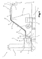
Fig. 1 ist ein Schweißgerät 1 bzw. eine Schweißanlage für verschiedenste Prozesse bzw. Verfahren, wie z.B. MIG/MAG-Schweißen bzw. WIG/TIG-Schweißen oder Elektroden-Schweißverfahren, Doppeldraht/Tandem-Schweißverfahren, Plasma- oder Lötverfahren usw., gezeigt. - Das Schweißgerät 1 umfasst eine Stromquelle 2 mit einem Leistungsteil 3, einer Steuervorrichtung 4 und einem dem Leistungsteil 3 bzw. der Steuervorrichtung 4 zugeordneten Umschaltglied 5. Das Umschaltglied 5 bzw. die Steuervorrichtung 4 ist mit einem Steuerventil 6 verbunden, welches in einer Versorgungsleitung 7 für ein Gas 8, insbesondere ein Schutzgas, wie beispielsweise CO2, Helium oder Argon und dergl., zwischen einem Gasspeicher 9 und einem Schweißbrenner 10 bzw. einem Brenner angeordnet ist.
- Zudem kann über die Steuervorrichtung 4 noch ein Drahtvorschubgerät 11, welches für das MIG/MAG-Schweißen üblich ist, angesteuert werden, wobei über eine Versorgungsleitung 12 ein Zusatzwerkstoff bzw. ein Schweißdraht 13 von einer Vorratstrommel 14 bzw. einer Drahtrolle in den Bereich des Schweißbrenners 10 zugeführt wird. Selbstverständlich ist es möglich, dass das Drahtvorschubgerät 11, wie es aus dem Stand der Technik bekannt ist, im Schweißgerät 1, insbesondere im Grundgehäuse, integriert ist und nicht, wie in
Fig. 1 dargestellt, als Zusatzgerät ausgebildet ist. - Es ist auch möglich, dass das Drahtvorschubgerät 11 den Schweißdraht 13 bzw. den Zusatzwerkstoff außerhalb des Schweißbrenners 10 an die Prozessstelle zuführt, wobei hierzu im Schweißbrenner 10 bevorzugt eine nicht abschmelzende Elektrode angeordnet ist, wie dies beim WIG/TIG-Schweißen üblich ist.
- Der Strom zum Aufbauen eines Lichtbogens 15, insbesondere eines Arbeitslichtbogens, zwischen der nicht abschmelzenden Elektrode, nicht dargestellt, und einem Werkstück 16 wird über eine Schweißleitung 17 vom Leistungsteil 3 der Stromquelle 2 dem Schweißbrenner 10, insbesondere der Elektrode, zugeführt, wobei das zu verschweißende Werkstück 16, welches aus mehreren Teilen gebildet ist, über eine weitere Schweißleitung 18 ebenfalls mit dem Schweißgerät 1, insbesondere mit der Stromquelle 2, verbunden ist und somit über den Lichtbogen 15 bzw. den gebildeten Plasmastrahl für einen Prozess ein Stromkreis aufgebaut werden kann.
- Zum Kühlen des Schweißbrenners 10 kann über einen Kühlkreislauf 19 der Schweißbrenner 10 unter Zwischenschaltung eines Strömungswächters 20 mit einem Flüssigkeitsbehälter, insbesondere einem Wasserbehälter 21, verbunden werden, wodurch bei der Inbetriebnahme des Schweißbrenners 10 der Kühlkreislauf 19, insbesondere eine für die im Wasserbehälter 21 angeordnete Flüssigkeit verwendete Flüssigkeitspumpe, gestartet wird und somit eine Kühlung des Schweißbrenners 10 bewirkt werden kann.
- Das Schweißgerät 1 weist weiters eine Ein- und/oder Ausgabevorrichtung 22 auf, über die die unterschiedlichsten Schweißparameter, Betriebsarten oder Schweißprogramme des Schweißgerätes 1 eingestellt bzw. aufgerufen werden können. Dabei werden die über die Ein- und/oder Ausgabevorrichtung 22 eingestellten Schweißparameter, Betriebsarten oder Schweißprogramme an die Steuervorrichtung 4 weitergeleitet und von dieser werden anschließend die einzelnen Komponenten der Schweißanlage bzw. des Schweißgerätes 1 angesteuert bzw. entsprechende Sollwerte für die Regelung oder Steuerung vorgegeben.
- Weiters ist in dem dargestellten Ausführungsbeispiel der Schweißbrenner 10 über ein Schlauchpaket 23 mit dem Schweißgerät 1 bzw. der Schweißanlage verbunden. In dem Schlauchpaket 23 sind die einzelnen Leitungen vom Schweißgerät 1 zum Schweißbrenner 10 angeordnet. Das Schlauchpaket 23 wird über eine Kupplungsvorrichtung 24 mit dem Schweißbrenner 10 verbunden, wogegen die einzelnen Leitungen im Schlauchpaket 23 mit den einzelnen Kontakten bzw. Anschlüssen des Schweißgerätes 1 über Anschlussbuchsen bzw. Steckverbindungen verbunden sind. Damit eine entsprechende Zugentlastung des Schlauchpaketes 23 gewährleistet ist, ist das Schlauchpaket 23 über eine Zugentlastungsvorrichtung 25 mit einem Gehäuse 26, insbesondere mit dem Grundgehäuse des Schweißgerätes 1, verbunden. Selbstverständlich ist es möglich, dass die Kupplungsvorrichtung 24 auch für die Verbindung am Schweißgerät 1 - anstelle der Anschlussbuchsen bzw. Steckverbindungen - eingesetzt werden kann. Auf diese Art und Weise wird beispielsweise mit der Kupplungsvorrichtung 24 ein Anschlusssystem 27 für den Schweißbrenner 10 gebildet.
- Grundsätzlich ist zu erwähnen, dass für die unterschiedlichen Schweißverfahren bzw. Schweißgeräte 1, wie beispielsweise WIG-Geräte oder MIG/MAG-Geräte oder Plasmageräte, nicht alle zuvor benannten Komponenten verwendet bzw. eingesetzt werden müssen. Hierzu ist es beispielsweise möglich, dass der Schweißbrenner 10 als luftgekühlter Schweißbrenner 10 ausgeführt werden kann.
- Wie bereits angesprochen, wird der Schweißbrenner 10 bei einem MIG/MAG - Schweißprozess mit unterschiedlichen Medien (wie Gas und Schweißstrom) versorgt und insbesondere ein Schweißdraht 13 zum Schweißbrenner 10 geführt. Dieser Schweißdraht 13 befindet sich entweder im Drahtvorschubgerät 11 oder im Schweißgerät 1 auf der Vorratstrommel 14, sodass dieser von einer auf einer Motorplatte 28 angeordneten Vorschubeinheit 29 gefördert werden kann. Das heißt, dass der Schweißdraht 13 von der Vorratstrommel 14, über die Motorplatte 28, das Anschlusssystem 27 und das Schlauchpaket 23 zum Schweißbrenner 10 gefördert ist.
- In dem Beispiel ist nun vorgesehen, dass ein Anschlusssystem 27 für den Schweißbrenner 10 eine Anschlussvorrichtung 30 umfasst, welche durch eine Stirnwand 38 und eine Trennwand 39 der Motorplatte 28 gebildet ist. Ebenso sind die Anschlüsse des Anschlusssystems 27 auf unterschiedliche Ebenen (31, 32, 33) aufgeteilt.
- Im Folgenden wird nun das Anschlusssystem 27 anhand eines Ausführungsbeispiels beschrieben. Dabei wird das Anschlusssystem 27 durch die Kupplungsvorrichtung 24 und einem Steckelement 34 gebildet, wobei die Kupplungsvorrichtung 24 die Anschlussvorrichtung 30, eine Kupplung 35 und eine Stromkupplung 36 umfasst. Das Steckelement 34 ist dabei an einem Ende des Schlauchpakets 23 befestigt, wobei am anderen Ende der Schweißbrenner 10 befestigt ist. Dementsprechend wird also das Steckelement 34 (im Folgenden auch Stecker 34 genannt) beim Verbinden des Anschlusssystems 27 mit der Kupplung 35, der Anschlussvorrichtung 30 und der Stromkupplung 36 verbunden.
- Das Anschlusssystem 27 ist nun aus der Zusammenschau der
Fig. 2 bis 11 ersichtlich. Grundsätzlich hat das Anschlusssystem 27 die Aufgabe, die für einen Schweißprozess erforderlichen Medien wie den Schweißstrom, das Gas 8, Steuersignale 40, den Schweißdraht 13 und dergleichen dem Schweißbrenner 10 zur Verfügung zu stellen, wie allgemein aus dem Stand der Technik bekannt. Entsprechend ist beispielsweise für jedes dieser Medien eine Leitung im Schlauchpaket 23 vorgesehen. Ebenso ist für jedes Medium sowohl in der Kupplungsvorrichtung 24 als auch im Stecker 34 ein Anschluss vorgesehen. - Um allerdings diese Vielzahl der Medien Platz sparend über einen Stecker 34 zu übertragen, sind die Anschlüsse der Kupplungsvorrichtung 24 für den Stecker 34 vorteilhaft in unterschiedliche Ebenen 31, 32, 33 aufgeteilt. Dazu sind entsprechend die Kupplung 35 und die Stromkupplung 36 erforderlich, welche fluchtend hintereinander angeordnet sind. Das heißt, dass der Übergang der unterschiedlichen Medien an unterschiedlichen Stellen - sprich den Ebenen 31, 32, 33 - erfolgt, wie insbesondere aus den
Fig. 2 bis 4 ersichtlich. - Der Schweißdraht 13 wird hierbei im Wesentlichen direkt von der auf der Motorplatte 28 angeordneten Vorschubeinheit 29 auf den Stecker 34 übertragen. Es kann auch gesagt werden, dass der von der Vorschubeinheit 29 geförderte Schweißdraht 13 vom Stecker 34 aufgenommen wird, sodass dieser über das Schlauchpaket 23 zum Schweißbrenner 10 geführt werden kann. Dies ist erfindungsgemäß bereits dadurch gewährleistet, wenn ein Bolzen 37 des Steckers 34 in der Anschlussvorrichtung 30 positioniert wird. Wird das Anschlusssystem 27 für einen Handschweißbrenner eingesetzt, ist es im Wesentlichen erforderlich, auch die weiteren Medien zu übertragen.
- Vorteilhaft sind daher die Kupplung 35 und die Stromkupplung 36 vorgesehen, welche an der Anschlussvorrichtung 30 der Motorplatte 28 angeordnet sind, sodass die weiteren Medien unmittelbar nach dem Schweißdraht 13 - in Richtung des Schweißbrenners 10 gesehen - auf den Stecker 34 übertragen werden können. Dazu weist die Anschlussvorrichtung 30 eine Stirnwand 38 und eine Trennwand 39 auf, wobei die Stromkupplung 36 zwischen Stirnwand 38 und Trennwand 39 angeordnet ist und die Kupplung 35 an der Stirnwand 38 befestigt ist. Somit ist die Stromkupplung 36 auf der Motorplatte 28 und die Kupplung 35 an der Motorplatte 28 befestigt.
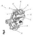
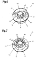
- Die Kupplung 35 ist dabei bevorzugt aus einem elektrisch nicht leitenden Material wie Kunststoff gebildet und zur Übertragung folgender Medien ausgebildet: elf Steuersignale 40, das Gas 8, eine Luft 42 und einen Datenbus 43. Demzufolge weist die Kupplung 35 vierzehn Anschlüsse auf, welche im Wesentlichen im Kreis angeordnet sind, wie insbesondere aus den
Fig. 6 und 7 ersichtlich. Dabei weisen die Anschlüsse für die Steuersignale 40 abwechselnd unterschiedliche Höhen auf, sodass die erforderlichen Luft- und Kriechstrecken auf engstem Raum eingehalten werden können. Zusätzlich weist die Kupplung 35 um den Mittelpunkt des Kreises eine Durchführung 44 auf, sodass die weiteren Medien hinter der Kupplung 35 - in Richtung der Vorschubeinheit 29 - auf den Stecker 34 übertragen werden können. Dies betrifft im Wesentlichen den Schweißstrom und den Schweißdraht 13. Somit bildet die Durchführung 44 eine Verbindung zur Anschlussvorrichtung 30, in welcher der Schweißstrom und der Schweißdraht 13 übertragen werden. Der Schweißstrom wird dabei von der Stromkupplung 36 über den Bolzen 37 auf den Stecker 34 übertragen, also unmittelbar hinter der Kupplung 35. Demzufolge wird aus Sicht in Richtung der Vorschubeinheit 29 der Schweißdraht 13 ganz hinten vom Stecker 34 aufgenommen - nämlich im Wesentlichen in der Trennwand 39 der Anschlussvorrichtung 30. - Somit kann gesagt werden, dass die vierzehn Anschlüsse der Kupplung 35 um einen Anschluss der Stromkupplung 36 und einen Anschluss zur Aufnahme des Schweißdrahts 13 ergänzt wird. Das heißt aber auch, dass drei Ebenen 31, 32, 33 für Anschlüsse gebildet werden, wobei die erste Ebene 31 durch die Kupplung 35, die zweite Ebene 32 durch die Stromkupplung 36 und die dritte Ebene 33 durch den Anschluss zur Aufnahme des Schweißdrahts 13 gebildet wird.
- Der Anschluss zur Aufnahme des Schweißdrahts 13 ergibt sich dabei zum einen aus den Anordnungen von Kupplung 35, Stirnwand 38, Stromkupplung 36, Trennwand 39 und Vorschubeinheit 29 und zum anderen aus dem Stecker 34.
- Der Stecker 34 muss demzufolge derart ausgebildet sein, dass die Medien über die auf drei Ebenen 31, 32, 33 aufgeteilten Anschlüsse der Kupplungsvorrichtung 24 auf die zu diesen Anschlüssen korrespondierenden Anschlüsse des Steckers 34 übertragen werden können - siehe insbesondere
Fig. 2 ,3 und11 . Dazu ist der Stecker 34 im Wesentlichen korrespondierend zur Kupplung 35 aufgebaut, wobei anstelle der Durchführung 44 der Kupplung 35 der Bolzen 37 am Stecker 34 angeordnet ist. Dieser Bolzen 37 stellt im Wesentlichen den am Stecker 34 korrespondierenden Anschluss für den Schweißstrom dar und bildet mit der an dessen freien Ende angeordneten Einlaufdüse 45 den Anschluss zur Aufnahme des Schweißdrahts 13. - Das heißt, dass beim Verbinden des Anschlusssystems 27 in einem ersten Schritt der Bolzen 37 des Steckers 34 durch die Durchführung 44 der Kupplung 35, anschließend durch eine Ausnehmung 46 der Stirnwand 38 und in weiterer Folge durch eine Durchführung 47 der Stromkupplung 36 geführt ist. In diesem Status ist der Stecker 34 zentriert und durch den in der Kupplung 35, der Stirnwand 38 und der Stromkupplung 36 geführten Bolzen 37 gehalten, sodass der Stecker 34 in einfacher Weise in einem zweiten Schritt in die richtige Position gemäß einem Verdrehschutz gebracht werden kann. Der Verdrehschutz wird dabei bevorzugt durch die Anschlüsse der Luft 42, des Gases 8 und/oder des Datenbusses 43 gebildet, da diese im Vergleich zu den Steuersignalen 40 größer sind. Somit ist gewährleistet, dass keiner dieser drei Anschlüsse mit einem Steuersignal 40 verbunden wird. Diese Anschlüsse werden dementsprechend zuerst verbunden, also vor den Anschlüssen der Steuersignale 40. Somit können in einem dritten Schritt die Anschlüsse der Kupplung 35 mit den korrespondierenden Anschlüssen des Steckers 34 in der ersten Ebene 31 verbunden und gleichzeitig der Bolzen 37 in einer Ausnehmung 48 der Trennwand 39 positioniert und zentriert werden. Demzufolge ist in der Ausnehmung 48 der Trennwand 39 eine Art Anschlag 56 angeordnet, sodass lediglich ein Teil der Einlaufdüse 45 durch die Ausnehmung 48 ragt. Dadurch wird entsprechend auch der Abstand zwischen dem Austritt des Schweißdrahts 13 aus zwei Förderrollen der Vorschubeinheit 29 und der Einlaufdüse 45 auf ein Minimum reduziert bzw. können die Förderrollen unmittelbar vor der Einlaufdüse 45 angeordnet werden, sodass eine präzise Führung des Schweißdrahts 13 gewährleistet ist. Somit hat die Ausnehmung 48 zwei unterschiedliche Durchmesser, wobei im größeren Durchmesser der Bolzen 37 und im kleineren Durchmesser die Einlaufdüse 45 - welche sozusagen schwimmend im Bolzen 37 gelagert ist - zentriert wird. Somit ist auch durch die Länge des Bolzens 37 und dem Anschlag 56 definiert, wann die Anschlüsse der Medien korrekt verbunden sind. In diesem Status ist somit auch der Anschluss zur Aufnahme des Schweißdrahts 13 vollständig gebildet. Das heißt, dass die Aufnahme für den Schweißdraht 13 durch die in der Ausnehmung 48 der Trennwand 39 zentrierte Einlaufdüse 45 des Bolzens 37 fluchtend mit der Förderachse des Schweißdrahtes 13 ist, sodass der Schweißdraht 13 im Wesentlichen automatisch aufgenommen werden kann. Somit sind in diesem Status alle Anschlüsse verbunden, bis auf die vollständige Übertragung des Schweißstroms, wie insbesondere aus
Fig. 4 ersichtlich. Hieraus ist entsprechend zu entnehmen, dass die Durchführungen 44, 47 der Kupplung 35 und der Stromkupplung 36 mit der Ausnehmungen 46, 48 der Stirnwand 38 und der Trennwand 39 fluchtend sind. Dadurch ist auch eine Mittelachse des Bolzens 37 mit der Förderachse des Schweißdrahts 13 fluchtend. - Allgemein weist der Bolzen 37 einen Durchmesser auf, mit welchem im Wesentlichen ein großer Bereich für den Schweißstrom übertragen werden kann. Somit kann der Bolzen 37 für fast alle Anwendungen verwendet werden. Zusätzlich muss der Durchmesser des Bolzens 37 auch dazu ausgelegt sein, dass das Gewicht des Steckelements 34 gehalten werden kann. Dies wird im Wesentlichen durch einen Durchmesser im Bereich um 17 mm erreicht. Beispielsweise beträgt der Durchmesser 17.31 mm.
- Die Übertragung des Schweißstroms erfolgt nun derart, dass die Stromkupplung 36 - wie insbesondere anhand der
Fig. 8 bis 10 gezeigt - mit einem Verriegelungssystem 49 ausgebildet ist, welches beim Verbinden des Anschlusssystems 27 geöffnet sein muss. Das Verriegelungssystem 49 bewirkt beim Schließen, dass der Bolzen 37 im Wesentlichen vollständig umschlossen wird und mit einer definierten Kraft geklemmt wird, wie insbesondere inFig. 10 dargestellt. Dazu weist das Verriegelungssystem 49 im Wesentlichen einen Hebel 50 auf, welcher bevorzugt mit einem Messingteil 51 der Stromkupplung 36 verbunden ist, wobei zumindest der Messingteil 51 elektrisch leitfähig ist. Der bevorzugt einteilige Messingteil 51 wird dabei sozusagen in einen starren Teil 52 und einen flexiblen Teil 53 unterteilt. Die Durchführung 47 für den Bolzen 37 ist dabei im Bereich des starren Teils 52 angeordnet. Des Weiteren verbindet der Hebel 50 auf einer Seite den flexiblen Teil 53 mit dem starren Teil 52, sodass bei einer Betätigung des Hebels 50 aufgrund einer exzentrischen Kraft der Durchmesser der Durchführung 47 verkleinert wird und der Bolzen 37 geklemmt wird. Der flexible Teil 53 wirkt zusätzlich auch als Feder, wodurch Toleranzunterschiede der Bolzen 37 ausgeglichen werden und der Todpunkt des Verriegelungssystems 49 überwunden werden kann. Somit kann der geschlossene Hebel 50 im Wesentlichen als Selbstsichernder Hebel 50 betrachtet werden. Durch den geschlossenen Hebel 50 ergibt sich auch eine Fläche, welche den Bolzen 37 einklemmt und über welche der Schweißstrom auf den Bolzen 37 übertragen wird. Entsprechend ist die Fläche auf die Höhe des Schweißstroms abgestimmt. Damit der Schweißstrom auf den Bolzen 37 übertragen werden kann, ist die Stromkupplung 36 innen an der Stirnwand 38 befestigt, wobei die Zuleitung für den Schweißstrom allgemein an der Motorplatte 28 angeschlossen ist. Somit wird der Schweißstrom von der Zuleitung über die Motorplatte 28 auf die Stromkupplung 36 übertragen, sodass schlussendlich der Schweißstrom auf den Bolzen 37 übertragen werden kann. Selbstverständlich ist es auch möglich, dass die Zuleitung für den Schweißstrom beispielsweise direkt an der Stromkupplung 36 angeschlossen wird. Durch eine derartige Befestigung der Stromkupplung 36 wird auch erreicht, dass die Durchführung 47 bei der Montage fluchtend ausgerichtet werden kann. Zusätzlich kann der Hebel 50 auch derart geformt sein, dass ein Teil des Hebels 50 - ein Gegenstück 57 - beim Schließen in einer Nut 54 des Bolzens 37 einrastet und diesen zusätzlich sichert, wie im Detail ausFig. 10 ersichtlich. - Die Stromkupplung 36 wird also innen an der Stirnwand 38 befestigt, wobei die Befestigung bevorzugt über Schrauben erfolgt. Diese werden von außen - durch die Stirnwand 38 hindurch - mit dem Gewinde im starren Teil 52 der Stromkupplung 36 verbunden. Somit ist kein Gewinde in der Stirnwand 38 vorgesehen, wodurch eine exakte Ausrichtung der Durchführung 47 gegeben ist.
- Nachdem also die Stromkupplung 36 montiert wurde, kann die Kupplung 35 außen an der Stirnwand 38 - den so genannten Flansch - montiert werden. Dabei werden die Schrauben - die nicht bezeichneten Kreise auf der Stirnwand 38 in
Fig. 5 - zur Befestigung der Stromkupplung 36 verdeckt. Wesentlich ist einerseits, dass die Befestigung der Kupplung 35 im Wesentlichen auf der Höhe der Mittelachse der Ausnehmung 46 erfolgt, indem beispielsweise links und rechts bzw. oben und unten (je nach Einbaulage der Motorplatte 28) der Ausnehmung 46 ein Befestigungselement 41 bzw. ein Gewinde 41 vorgesehen ist. Somit ist gewährleistet, dass das Gewicht des Steckers 34 über die Befestigung gehalten wird und die Beanspruchungen für die Kupplung 35 - beispielsweise beim Entfernen des Steckers 34 - minimal gehalten werden. - Auch ist die Durchführung 44 der Kupplung 35 als Führung für den Bolzen 37 des Steckers 34 ausgebildet, wobei diese elektrisch isolierend ist. Diese Führung weist im Wesentlichen eine Länge von einigen Zentimetern auf und bildet mit der Stärke der Stirnwand 38 die Distanz zwischen der ersten Ebene 31 und der zweiten Ebene 32. Neben der Führung hat diese Distanz auch den zweiten Effekt, dass die Anschlusszuleitungen für die Anschlüsse der Kupplung 35 (wie Steuersignale 40, Datenbus 43 und Luft 42) geführt werden können. Es ist aber auch möglich, dass die Durchführung 44 elektrisch leitfähig ausgebildet ist. Somit kann beispielsweise ein zusätzlicher Stromübergang in der Durchführung 44 erfolgen. Dazu kann gegebenenfalls eine Feder eingesetzt werden, welche den Bolzen 37 umschließt und den Strom auf diesen überträgt.
- Zusätzlich kann in der Stirnwand 38 auch ein Gasversorgungsanschluss 55 vorgesehen sein, welcher bevorzugt fluchtend mit dem Anschluss für das Gas 8 der Kupplung 35 positioniert ist. Daher ist bei der Befestigung der Kupplung 35 der Gasanschluss 8 der Kupplung 35 automatisch mit dem Gasversorgungsanschluss 55 der Stirnwand 38 verbunden. Dieser Gasversorgungsanschluss 55 verläuft im Wesentlichen zur Unterseite der Grundplatte der Motorplatte 28, wo die Gaszuleitung und die Zuleitung für den Schweißstrom angeschlossen wird. In diesem Fall sind also für die Kupplung 35 vier Punkte von Bedeutung, nämlich die Ausnehmung 46 der Stirnwand 38, die zwei Gewinde 41 und der Gasversorgungsanschluss 55. Die Abstände dieser Punkte zueinander muss im Wesentlichen eingehalten werden, sodass die Medien über die Anschlussvorrichtung 30 zum Schweißbrenner 10 übertragen werden können. Die Abstände sind dabei im Wesentlichen auf eine Mediendurchführung eines Roboters - wie beispielsweise einem so genannten Hohlwellenroboter - abgestimmt. Eine derartige Mediendurchführung hat einen Durchmesser im Bereich um 42 mm. Somit muss entsprechend der Außendurchmesser des Steckers 34 zumindest minimal unter diesem Bereich liegen. Erreicht wird dies, wie bereits angesprochen, durch die Aufteilung der Anschlüsse auf die unterschiedliche Ebenen 31, 32, 33. Aufgrund einer derartigen Mediendurchführung im Bereich um 42 mm ergeben sich folgende Abstände für die Befestigung der Kupplung 35:
- Der Abstand vom Mittelpunkt des Gewindes 41 zum Mittelpunkt der Ausnehmung 46 der Stirnwand 38 beträgt im Wesentlichen 28 mm. Dabei sind die Gewinde 41 im Wesentlichen auf einer Senkrechten durch den Mittelpunkt der Ausnehmung 46 der Stirnwand 38 angeordnet. Der Abstand zwischen dem Mittelpunkt der Ausnehmung der Stirnwand 38 und dem Mittelpunkt des Gasversorgungsanschlusses 55 beträgt im Wesentlichen 14 mm. Dabei ist der Mittelpunkt des Gasversorgungsanschlusses 55 auf einer Waagrechten durch den Mittelpunkt der Ausnehmung 46 der Stirnwand 38 angeordnet. Diese Anordnung von Gewinde 41, Ausnehmung 46 und Gasversorgungsanschluss 55 ist im Wesentlichen aus
Fig. 5 ersichtlich, wobei dies die übliche Einbaulage der Motorplatte 28 ist. Da hier die Motorplatte 28 sozusagen stehend dargestellt ist, ergibt sich die Senkrechte bzw. die Waagrechte wie zuvor beschrieben. Wird entsprechend die Motorplatte 28 liegend eingebaut, ist die Senkrechte bzw. die Waagrechte zu vertauschen. - Das offenbarte Anschlusssystem 27 ist somit im Wesentlichen aufgrund des runden Steckers 34 für einen Hohlwellenroboter geeignet, wobei sämtliche zwingend erforderliche Medien und zusätzliche Medien über den einzigen Stecker 34 zum Schweißbrenner 10 übertragen werden. Ein zusätzliches Medium ist beispielsweise die Luft 42, welche zum so genannten Ausblasen verwendet werden kann. Ein weiteres zusätzliches Medium kann auch über eine der Steuerleitungen 40 übertragen werden, wie das Suchen einer Gasdüsenposition.
- Für eine im Wesentlichen verlustfreie Übertragung der Medien ist es von Bedeutung, dass das Anschlusssystem 27 vollständig verbunden ist. Dies wird im Wesentlichen dadurch kontrolliert, ob der Hebel 50 des Verriegelungssystems 49 geschlossen werden kann. Das heißt, wenn sich der Hebel 50 schließen lässt, ist das Anschlusssystem 27 vollständig geschlossen und betriebsbereit. Lässt sich der Hebel 50 demnach nicht vollständig schließen, ist der Stecker 34 nicht korrekt positioniert. Diese Kontrolle ergibt sich aus der Nut 54 im Bolzen 37 und einem entsprechenden Gegenstück 57 des Hebels 50, welches in der Nut 54 versenkt wird (
Fig. 10 ). Somit wird der Bolzen 37 zum einen in der Durchführung 47 der Stromkupplung 36 eingeklemmt und andererseits auch über die Nut 54 fixiert, sodass im Wesentlichen eine doppelte Sicherung gegen eine Änderung der Position des Steckers 34 gegeben ist. Entsprechend erfolgen dabei die Klemmung und die Sicherung über die Nut 54 gemeinsam mit dem Hebel 50. - Dadurch ist aber auch gewährleistet, dass die Einlaufdüse 45 bzw. der Bolzen 37 in der Trennwand 39 korrekt positioniert und zentriert ist. Somit kann der Schweißdraht 13 reibungsarm von der Einlaufdüse 45 aufgenommen werden. Der Anschlag 56 in der Trennwand 39 hat hierbei auch die Aufgabe, eine spürbare Endposition des Steckers 34 darzustellen und die weiteren Anschlüsse vor einer Überbelastung zu schützen.
- Eine vollständige Verbindung des Anschlusssystems 27 ist auch für den Datenbus 43 von Bedeutung, da dieser als so genannter High-Speed-Datenbus 43 ausgebildet ist. Dazu ist eine entsprechende Schirmung in der Steckverbindung erforderlich, da in unmittelbarer Nähe der Bolzen 37, welcher einen Schweißstrom von beispielsweise 500A führt, angeordnet ist. Der Übergang von einem High-Speed-Kabel des Datenbusses 43 auf die Steckverbindung erfolgt dabei in der Distanz zwischen der ersten Ebene 31 und der zweiten Ebene 32.
- Das Anschlusssystem 27 bzw. der Hebel 50 lässt sich demnach nur dann vollständig schließen, wenn der Stecker 34 bis zum Anschlag 56 in der Trennwand 39 der Anschlussvorrichtung 30 geschoben wird oder die Einlaufdüse 45 in der Durchführung 47 der Stromkupplung 36 endet. Sollte letzteres der Fall sein, wird lediglich der Schweißstrom übertragen und es ist für den Schweißer ersichtlich, dass der Stecker 34 weiter hinein geschoben werden muss.
- Selbstverständlich kann ein vollständig verbundenes Anschlusssystem 27 auch beispielsweise dadurch erkannt werden, indem ein Steuersignal 40 der Kupplung 35 erst dann mit dem korrespondierenden Anschluss des Steckers 34 kontaktiert wird, wenn der Stecker 34 bis zum Anschlag 56 eingeschoben ist. Entsprechend kann auch beispielsweise ein Kontakt in der Kupplung 35 mit dem Stecker 34 geschlossen werden oder ein Schalter in der Kupplung 35 betätigt werden, sodass kein Steuersignal 40 erforderlich ist.
- Allgemein ist die Motorplatte 28 auch derart ausgebildet, dass die Anschlussvorrichtung 30 beidseitig angeordnet ist. Demzufolge also vor und nach der Vorschubeinheit 29, sodass ein symmetrischer Aufbau der Motorplatte 28 gegeben ist. Somit kann die Motorplatte 28 auch in einem so genannten Zwischenantrieb eingesetzt werden, durch welchen das Schlauchpaket 23 im Wesentlichen unterbrochen wird. Das Anschlusssystem 27 ist allerdings überall gleich und somit einheitlich.
- Das Anschlusssystem 27 ist durch die Anschlussvorrichtung 30 der Motorplatte 28 auch äußerst flexibel einsetzbar. So kann beispielsweise ein so genannter Maschinenbrenner für Roboter direkt an der Anschlussvorrichtung 30 angeschlossen werden, ohne dass eine Kupplung 35 erforderlich ist. Dies ist darauf zurückzuführen, dass ein derartiger Maschinenbrenner lediglich eine begrenzte Anzahl von Medien benötigt. Meist nur den Schweißstrom, das Gas 8 und den Schweißdraht 13. Diese Medien können über die Anschlussvorrichtung 30 und die Stromkupplung 36 auf den Stecker 34 übertragen werden. Hierzu kann beispielsweise entweder ein verkürzter Bolzen 37, sodass der Gasanschluss 8 des Steckers 34 direkt mit dem Gasversorgungsanschluss 55 verbindbar ist, oder ein Zwischenstück zwischen dem Gasanschluss 8 des Steckers 34 und dem Gasversorgungsanschluss 55, eingesetzt werden. Gegebenenfalls kann auch die Stromkupplung 36 weggelassen werden, sodass die Medien ausschließlich über die Anschlussvorrichtung 30 übertragen werden. Dazu sind beispielsweise in den Ausnehmungen 46 der Stirnwand 38 und der Trennwand 39 Federn integriert, welche den Schweißstrom auf den Bolzen 37 übertragen. Diese Federn können entsprechend auch in jeder Ausführungsform des Anschlusssystems 27 eingesetzt werden, beispielsweise auch in der Durchführung 47 der Stromkupplung 36.
- Das Anschlusssystem 27 kann aber auch derart ausgebildet sein, dass das Steckelement 34 bzw. die Kupplung 35 durch einen Adapter gebildet ist. Dabei wird entsprechend das Schlauchpaket 23 am Adapter angeschlossen. Die Form des Adapters entspricht dabei im Wesentlichen entweder der Form des Steckelements 34 bzw. des Steckers 34 oder einer Kombination zwischen Stecker 34 und Kupplung 35. Auf jeden Fall benötigt der Adapter den Bolzen 37, welcher entsprechend in der Anschlussvorrichtung 30 positioniert wird. So ist beispielsweise bei der Kombination von Stecker 34 und Kupplung 35 als Adapter der Bolzen 37 im Wesentlichen an der Kupplung 35 befestigt, welche entsprechend auch an der Stirnwand 38 befestigt wird. Dabei stellt der Bolzen 37 die Verbindung zwischen Kupplung 35 und Anschlussvorrichtung 30 dar. Entspricht hingegen der Adapter dem Stecker 34, so wird im Wesentlichen der Adapter anstelle des Steckers 34 mit der Kupplung 35, der Anschlussvorrichtung 30 und der Stromkupplung 36 verbunden.
- Dadurch kann jeweils das Schlauchpaket 23 am Adapter befestigt werden. Die weiteren Medien können entsprechend über eine eigene Schnittstelle und/oder aber auch über den Adapter übertragen werden. Die Schnittstelle ist dabei meist neben dem Adapter angeordnet. Somit könnten an der Anschlussvorrichtung 30 auch Schlauchpakete 23 angeschlossen werden, welche nicht mit dem erfindungsgemäßen Stecker 34 versehen sind.
- Grundsätzlich kann also gesagt werden, dass das Steckelement 34 mit dem Schlauchpaket 23 verbunden ist. Diese Verbindung zwischen dem Steckelement 34 und dem Schlauchpaket 23 stellt einen Übergang dar, welcher allerdings unterschiedlich ausgebildet sein kann: Zum Einen, dass das Steckelement 34 - wie im Ausführungsbeispiel beschrieben - an einem Ende des Schlauchpakets 23 befestigt ist.
- Zum Zweiten, dass das Steckelement 34 ein Adapter ist, welcher aus der Kupplung 35 und dem Bolzen 37 gebildet wird. In diesem Fall muss anstelle des Steckelements 34 ein Anschlusselement am Ende des Schlauchpakets 23 befestigt sein, welches das Schlauchpaket 23 mit der Kupplung 35 verbindet. Somit ist das Schlauchpaket 23 über das Anschlusselement mit dem Steckelement 34 bzw. dem Adapter verbunden.
- Dies ist auch der Fall, wenn der Adapter dem Steckelement 34 entspricht.
- Der Ordnung halber sei abschließend darauf hingewiesen, dass zum besseren Verständnis des Aufbaus der erfindungsgemäßen Gegenstände diese bzw. deren Bestandteile teilweise unmaßstäblich und/oder vergrößert und/oder verkleinert dargestellt wurden.
- Die den eigenständigen erfinderischen Lösungen zugrundeliegende Aufgabe kann der Beschreibung entnommen werden.
- Vor allem können die einzelnen in den
Fig. 1 bis 11 gezeigten Ausführungen den Gegenstand von eigenständigen erfindungsgemäßen Lösungen bilden. Die diesbezüglichen erfindungsgemäßen Aufgaben und Lösungen sind den Detailbeschreibungen dieser Figuren zu entnehmen.Bezugszeichenaufstellung 1 Schweißgerät 41 Gewinde 2 Stromquelle 42 Luft 3 Leistungsteil 43 Datenbus 4 Steuervorrichtung 44 Durchführung 5 Umschaltglied 45 Einlaufdüse 6 Steuerventil 46 Ausnehmung 7 Versorgungsleitung 47 Durchführung 8 Gas 48 Ausnehmung 9 Gasspeicher 49 Verriegelungssystem 10 Schweißbrenner 50 Hebel 11 Drahtvorschubgerät 51 Messingteil 12 Versorgungsleitung 52 Messingteil starr 13 Schweißdraht 53 Messingteil flexibel 14 Vorratstrommel 54 Nut 15 Lichtbogen 55 Gasversorgungsanschluss 16 Werkstück 56 Anschlag 17 Schweißleitung 57 Gegenstück 18 Scheißleitung 19 Kühlkreislauf 20 Strömungswächter 21 Wasserbehälter 22 Ein- und/oder Ausgabevorrichtung 23 Schlauchpaket 24 Kupplungsvorrichtung 25 Zugentlastungsvorrichtung 26 Gehäuse 27 Anschlusssystem 28 Motorplatte 29 Vorschubeinheit 30 Anschlussvorrichtung 31 erste Ebene 32 zweite Ebene 33 dritte Ebene 34 Steckelement 35 Kupplung 36 Stromkupplung 37 Bolzen 38 Stirnwand 39 Trennwand 40 Steuersignale
Claims (4)
- Steckelement (34) für ein Anschlusssystem (27) eines Schweißbrenners (10), welcher über zumindest ein Schlauchpaket (23) mit dem Anschlusssystem (27) verbunden ist, wobei über das Schlauchpaket (23) ein von einer auf einer Motorplatte (28) angeordneten Vorschubeinheit (29) geförderter Schweißdraht (13) und weitere Medien zum Schweißbrenner (10) geführt sind,
dadurch gekennzeichnet, dass
das Steckelement (34) zumindest mit einem Bolzen (37) versehen ist, an dessen freiem Ende eine Einlaufdüse (45) für einen Schweißdraht (13) angeordnet ist, wobei zumindest der Bolzen (37) zur Befestigung an einer durch einen Endbereich der Motorplatte (28) gebildeten Anschlussvorrichtung (30) ausgebildet ist und wobei im Bolzen (37) eine Nut (54) für ein Verriegelungssystem (49) einer Stromkupplung (36) integriert ist. - Steckelement (34) nach Anspruch 1, dadurch gekennzeichnet, dass- das Steckelement (34) mit einer Verbindung zur Übertragung der weiteren Medien in einer ersten Ebene (31) ausgebildet ist,- der Bolzen (37) einen Bereich zur Übertragung eines Schweißstroms in einer zweiten Ebene (32) aufweist und- die Einlaufdüse (45) für den Schweißdraht (13) in einer dritten Ebene (33) angeordnet ist.
- Steckelement (34) nach Anspruch 1 oder 2, dadurch gekennzeichnet, dass ein Außendurchmesser des Gehäuses an eine Mediendurchführung eines Schweißroboters angepasst ist.
- Steckelement (34) nach einem der Ansprüche 1 bis 3, dadurch gekennzeichnet, dass das Steckelement (34) als Adapter ausgebildet ist.
Priority Applications (1)
| Application Number | Priority Date | Filing Date | Title |
|---|---|---|---|
| PL15155580T PL2898978T3 (pl) | 2009-05-06 | 2010-05-06 | Element wtykowy do systemu przyłączeniowego palnika spawalniczego |
Applications Claiming Priority (3)
| Application Number | Priority Date | Filing Date | Title |
|---|---|---|---|
| AT0069009A AT508285B1 (de) | 2009-05-06 | 2009-05-06 | Anschlusssystem mit einer kupplungsvorrichtung und einem steckelement für einen schweissbrenner |
| EP10722910.6A EP2427296B1 (de) | 2009-05-06 | 2010-05-06 | SCHWEISSGERÄT MIT EINER KUPPLUNGSVORRICHTUNG UND EINEM STECKELEMENT FÜR EINEN SCHWEIßBRENNER |
| PCT/AT2010/000156 WO2010127377A1 (de) | 2009-05-06 | 2010-05-06 | ANSCHLUSSSYSTEM MIT EINER KOPPLUNGSVORRICHTUNG UND EINEM STECKELEMENT FÜR EINEN SCHWEIßBRENNER |
Related Parent Applications (2)
| Application Number | Title | Priority Date | Filing Date |
|---|---|---|---|
| EP10722910.6A Division EP2427296B1 (de) | 2009-05-06 | 2010-05-06 | SCHWEISSGERÄT MIT EINER KUPPLUNGSVORRICHTUNG UND EINEM STECKELEMENT FÜR EINEN SCHWEIßBRENNER |
| EP10722910.6A Division-Into EP2427296B1 (de) | 2009-05-06 | 2010-05-06 | SCHWEISSGERÄT MIT EINER KUPPLUNGSVORRICHTUNG UND EINEM STECKELEMENT FÜR EINEN SCHWEIßBRENNER |
Publications (3)
| Publication Number | Publication Date |
|---|---|
| EP2898978A2 true EP2898978A2 (de) | 2015-07-29 |
| EP2898978A3 EP2898978A3 (de) | 2016-01-20 |
| EP2898978B1 EP2898978B1 (de) | 2021-11-17 |
Family
ID=42697194
Family Applications (2)
| Application Number | Title | Priority Date | Filing Date |
|---|---|---|---|
| EP10722910.6A Active EP2427296B1 (de) | 2009-05-06 | 2010-05-06 | SCHWEISSGERÄT MIT EINER KUPPLUNGSVORRICHTUNG UND EINEM STECKELEMENT FÜR EINEN SCHWEIßBRENNER |
| EP15155580.2A Active EP2898978B1 (de) | 2009-05-06 | 2010-05-06 | Steckelement für ein Anschlusssystem eines Schweißbrenners |
Family Applications Before (1)
| Application Number | Title | Priority Date | Filing Date |
|---|---|---|---|
| EP10722910.6A Active EP2427296B1 (de) | 2009-05-06 | 2010-05-06 | SCHWEISSGERÄT MIT EINER KUPPLUNGSVORRICHTUNG UND EINEM STECKELEMENT FÜR EINEN SCHWEIßBRENNER |
Country Status (9)
| Country | Link |
|---|---|
| US (1) | US9040872B2 (de) |
| EP (2) | EP2427296B1 (de) |
| JP (2) | JP2012525978A (de) |
| CN (1) | CN102802859B (de) |
| AT (1) | AT508285B1 (de) |
| DE (2) | DE202010018547U1 (de) |
| ES (1) | ES2903354T3 (de) |
| PL (1) | PL2898978T3 (de) |
| WO (1) | WO2010127377A1 (de) |
Families Citing this family (11)
| Publication number | Priority date | Publication date | Assignee | Title |
|---|---|---|---|---|
| US10315269B2 (en) | 2010-12-16 | 2019-06-11 | Illinois Tool Works Inc. | Welding wire feeder with tongue and groove feature |
| US9586283B2 (en) | 2011-03-29 | 2017-03-07 | Illinois Tool Works Inc. | Wire feeder tensioner with definitive settings |
| JP5843683B2 (ja) * | 2012-03-28 | 2016-01-13 | 株式会社神戸製鋼所 | タンデム溶接トーチ |
| US10144086B2 (en) * | 2012-06-22 | 2018-12-04 | Hobart Brothers Company | Wire feeder drive assembly |
| US9517522B2 (en) * | 2012-09-05 | 2016-12-13 | Illinois Tool Works Inc. | Self-aligning wire feeder assembly |
| US9402650B2 (en) * | 2013-03-15 | 2016-08-02 | Smith & Nephew, Inc. | Surgical fastening |
| CN106112299A (zh) * | 2016-08-19 | 2016-11-16 | 高兴 | 一种u肋的焊接装置和焊接系统 |
| US11185942B2 (en) | 2016-10-31 | 2021-11-30 | Illinois Tool Works Inc. | Multi-process torch |
| EP3539360B1 (de) * | 2016-11-11 | 2023-07-05 | The ESAB Group Inc. | Brennergriff mit schnellkupplung |
| US20180290227A1 (en) * | 2017-04-07 | 2018-10-11 | Lincoln Global, Inc. | Self adjusting seals for wire feeder connection |
| US11738403B2 (en) | 2020-01-27 | 2023-08-29 | The Esab Group Inc. | Push pull torch |
Citations (7)
| Publication number | Priority date | Publication date | Assignee | Title |
|---|---|---|---|---|
| DE1219144B (de) | 1962-04-27 | 1966-06-16 | Oerlikon Buehrle Holding A G | Schutzgas-Lichtbogen-Schweissanlage mit kontinuierlich zugefuehrter und sich aufbrauchender Elektrode |
| CH670210A5 (en) | 1986-05-02 | 1989-05-31 | Mechafin Ag | Welding torch connecting coupling - with two insulating plastic halves joined by plastic union nut |
| CH681213A5 (en) | 1990-04-20 | 1993-02-15 | Mechafin Ag | Connection coupling for weld burner to current source - with split ring tube section fitting over bolt section with wedge shapes side butting flanges |
| DE9319418U1 (de) | 1993-12-17 | 1994-03-17 | Wilhelm Merkle Schweismaschine | Schweißvorrichtung |
| DE102004021937B3 (de) | 2004-05-04 | 2005-06-23 | Werner Jankus | Brenner für Schutzgas-Lichtbogenschweißung |
| US7274001B1 (en) | 2005-02-28 | 2007-09-25 | Cusick Iii Joseph Baxter | Cable assembly for arc welding |
| WO2007146963A2 (en) | 2006-06-12 | 2007-12-21 | Victor Equipment Company | Wire feeder with interchangeable adapter cartridges |
Family Cites Families (23)
| Publication number | Priority date | Publication date | Assignee | Title |
|---|---|---|---|---|
| US2819384A (en) * | 1955-11-25 | 1958-01-07 | Auto Arc Weld Mfg Co | Lubricant feeder for welding apparatus |
| US3629574A (en) * | 1969-01-28 | 1971-12-21 | Franklin Gno Corp | Apparatus and methods for separating electrons from ions |
| US3610875A (en) | 1970-02-11 | 1971-10-05 | Unitec Corp | Apparatus for conducting gas and electrical current |
| GB1354395A (en) * | 1971-10-20 | 1974-06-05 | Tweco Prod Inc | Semi-atuomatic welding apparatus |
| JPS5838538Y2 (ja) * | 1979-01-24 | 1983-08-31 | 株式会社神戸製鋼所 | 溶接用コンジツトケ−ブルコネクタ− |
| US4270824A (en) | 1979-03-30 | 1981-06-02 | Dover Corporation | Electrical clamp |
| US4549068A (en) * | 1983-12-09 | 1985-10-22 | Kensrue Milo M | Welding torch having swivel head assembly |
| US4582979A (en) * | 1984-09-10 | 1986-04-15 | Moerke Delford A | Arc welding system and docking assembly therefor |
| CN85101985A (zh) * | 1985-04-01 | 1987-01-31 | 特威可制品公司 | 焊枪接头总成 |
| SE449707B (sv) * | 1985-09-11 | 1987-05-18 | Esab Ab | Anordning for svetsning av ror i veggar, speciellt tuber i vermevexlargavlar |
| US4864099A (en) * | 1987-03-19 | 1989-09-05 | Tweco Products, Inc. | Water cooled semi-automatic welding gun |
| JPS63180180U (de) * | 1987-05-14 | 1988-11-21 | ||
| US5074802A (en) * | 1989-09-12 | 1991-12-24 | Hypertherm, Inc. | Pneumatic-electric quick disconnect connector for a plasma arc torch |
| JPH07124748A (ja) * | 1993-10-28 | 1995-05-16 | Akihiro Saito | コンジットケーブルと溶接トーチの清掃装置 |
| IT239387Y1 (it) * | 1995-03-16 | 2001-02-26 | Trafimet Spa | Attacco centralizzato per torce per taglio plasma |
| US6078023A (en) | 1998-04-27 | 2000-06-20 | Jones; Glen A. | Liquid-cooled welding torch assembly |
| HU223861B1 (hu) * | 1999-06-14 | 2005-02-28 | Antal Natta | Csatlakozó hegesztőpisztoly csatlakoztatásához |
| US6427894B1 (en) * | 2000-10-19 | 2002-08-06 | The Esab Group, Inc. | Electrode wire feeder for an arc welding system |
| US6472631B1 (en) | 2001-05-04 | 2002-10-29 | Hypertherm, Inc. | Strain relief mechanism for a plasma arc torch |
| US6713711B2 (en) | 2001-11-09 | 2004-03-30 | Thermal Dynamics Corporation | Plasma arc torch quick disconnect |
| US7285746B2 (en) * | 2004-04-08 | 2007-10-23 | Illinois Tool Works Inc. | Welding gun inlets |
| US7244911B2 (en) | 2005-04-08 | 2007-07-17 | Illinois Tool Works Inc. | Alignment mechanism for a welding torch |
| US8389899B2 (en) | 2005-09-12 | 2013-03-05 | Antal Natta | Connector for connecting welding torch |
-
2009
- 2009-05-06 AT AT0069009A patent/AT508285B1/de not_active IP Right Cessation
-
2010
- 2010-05-06 EP EP10722910.6A patent/EP2427296B1/de active Active
- 2010-05-06 WO PCT/AT2010/000156 patent/WO2010127377A1/de active Application Filing
- 2010-05-06 US US13/318,813 patent/US9040872B2/en active Active
- 2010-05-06 CN CN201080027038.8A patent/CN102802859B/zh active Active
- 2010-05-06 PL PL15155580T patent/PL2898978T3/pl unknown
- 2010-05-06 ES ES15155580T patent/ES2903354T3/es active Active
- 2010-05-06 DE DE202010018547.5U patent/DE202010018547U1/de not_active Expired - Lifetime
- 2010-05-06 EP EP15155580.2A patent/EP2898978B1/de active Active
- 2010-05-06 DE DE202010018548.3U patent/DE202010018548U1/de not_active Expired - Lifetime
- 2010-05-06 JP JP2012508852A patent/JP2012525978A/ja not_active Withdrawn
-
2015
- 2015-01-16 JP JP2015006846A patent/JP6027149B2/ja active Active
Patent Citations (7)
| Publication number | Priority date | Publication date | Assignee | Title |
|---|---|---|---|---|
| DE1219144B (de) | 1962-04-27 | 1966-06-16 | Oerlikon Buehrle Holding A G | Schutzgas-Lichtbogen-Schweissanlage mit kontinuierlich zugefuehrter und sich aufbrauchender Elektrode |
| CH670210A5 (en) | 1986-05-02 | 1989-05-31 | Mechafin Ag | Welding torch connecting coupling - with two insulating plastic halves joined by plastic union nut |
| CH681213A5 (en) | 1990-04-20 | 1993-02-15 | Mechafin Ag | Connection coupling for weld burner to current source - with split ring tube section fitting over bolt section with wedge shapes side butting flanges |
| DE9319418U1 (de) | 1993-12-17 | 1994-03-17 | Wilhelm Merkle Schweismaschine | Schweißvorrichtung |
| DE102004021937B3 (de) | 2004-05-04 | 2005-06-23 | Werner Jankus | Brenner für Schutzgas-Lichtbogenschweißung |
| US7274001B1 (en) | 2005-02-28 | 2007-09-25 | Cusick Iii Joseph Baxter | Cable assembly for arc welding |
| WO2007146963A2 (en) | 2006-06-12 | 2007-12-21 | Victor Equipment Company | Wire feeder with interchangeable adapter cartridges |
Also Published As
| Publication number | Publication date |
|---|---|
| AT508285A1 (de) | 2010-12-15 |
| ES2903354T3 (es) | 2022-04-01 |
| CN102802859A (zh) | 2012-11-28 |
| EP2427296A1 (de) | 2012-03-14 |
| EP2898978A3 (de) | 2016-01-20 |
| US9040872B2 (en) | 2015-05-26 |
| WO2010127377A1 (de) | 2010-11-11 |
| AT508285B1 (de) | 2011-11-15 |
| DE202010018547U1 (de) | 2017-08-07 |
| JP2015107526A (ja) | 2015-06-11 |
| PL2898978T3 (pl) | 2022-06-20 |
| US20120125905A1 (en) | 2012-05-24 |
| EP2898978B1 (de) | 2021-11-17 |
| CN102802859B (zh) | 2016-03-16 |
| DE202010018548U1 (de) | 2017-08-07 |
| JP2012525978A (ja) | 2012-10-25 |
| JP6027149B2 (ja) | 2016-11-16 |
| EP2427296B1 (de) | 2018-04-04 |
Similar Documents
| Publication | Publication Date | Title |
|---|---|---|
| EP2427296B1 (de) | SCHWEISSGERÄT MIT EINER KUPPLUNGSVORRICHTUNG UND EINEM STECKELEMENT FÜR EINEN SCHWEIßBRENNER | |
| EP2244855B1 (de) | Gasdüsenbefestigung | |
| EP1711300B1 (de) | Schweissbrenner mit einem brennergehäuse und antrieb zur schweissdrahtförderung | |
| DE102015212804B4 (de) | Steckerteil, Buchsenteil und Verbindungseinrichtung sowie Adapterelement zur lösbaren Verbindung eines flüssigkeitsgekühlten Schweißbrenners mit einem Schlauchpaket | |
| EP1689550B1 (de) | Schweissbrennervorrichtung zum anschluss an einen schweissroboter | |
| EP2603345B1 (de) | Brennerkörper mit einem befestigungssystem ; wig-schweissbrenner mit einem solchen brennerkörper | |
| EP2393624B1 (de) | STROMBUCHSE FÜR EIN SCHWEIßGERÄT | |
| WO2010135752A2 (de) | BRENNERWECHSELMODUL, SCHWEIßBRENNER, ROHRBOGEN, BRENNERHALTERUNG, SCHLAUCHPAKET FÜR EINEN SCHWEISSBRENNER, AUFNAHMEMODUL, BRENNERWECHSELSYSTEM UND VERFAHREN ZUM AUTOMATISCHEN WECHSELN EINES ROHRBOGENS ODER EINER BRENNERHALTERUNG EINES SCHWEISSBRENNERS | |
| WO2019057331A1 (de) | Schweissstromkabel zum anschluss an eine schweissstromquelle zur ausführung eines lichtbogenschweissverfahrens | |
| EP2819803B1 (de) | Steckerteil und buchsenteil zur lösbaren verbindung eines rohrbogens eines gasgekühlten schweissbrenners mit einem schlauchpaket sowie verbindungseinrichtung mit einem solchen steckerteil und einem solchen buchsenteil | |
| EP2673103B1 (de) | SCHWEIßGERÄT | |
| EP1549453A1 (de) | Abschaltbox f r eine roboteranlage | |
| AT512822B1 (de) | Steckelement für einen Schweißbrenner | |
| AT512823B1 (de) | Motorplatte für eine Schweißanlage | |
| AT512825B1 (de) | Stromkupplung für einen Schweißbrenner | |
| AT512824B1 (de) | Kupplung für ein Schlauchpaket eines Schweißbrenners | |
| WO2019057332A1 (de) | Schweissstromquelle | |
| EP3391986A1 (de) | Selbstanspassende dichtungen für einen drahtvorschubanschluss | |
| DE102014220114B4 (de) | Durchführungseinheit zur Durchführung elektrischer Energie durch eine Schwenkeinheit und System aus einer Schwenkeinheit und einer Durchführungseinheit | |
| AT7856U1 (de) | Abschaltbox für eine roboteranlage und roboteranlage mit einer abschaltbox |
Legal Events
| Date | Code | Title | Description |
|---|---|---|---|
| PUAI | Public reference made under article 153(3) epc to a published international application that has entered the european phase |
Free format text: ORIGINAL CODE: 0009012 |
|
| 17P | Request for examination filed |
Effective date: 20150218 |
|
| AC | Divisional application: reference to earlier application |
Ref document number: 2427296 Country of ref document: EP Kind code of ref document: P |
|
| AK | Designated contracting states |
Kind code of ref document: A2 Designated state(s): AL AT BE BG CH CY CZ DE DK EE ES FI FR GB GR HR HU IE IS IT LI LT LU LV MC MK MT NL NO PL PT RO SE SI SK SM TR |
|
| PUAL | Search report despatched |
Free format text: ORIGINAL CODE: 0009013 |
|
| AK | Designated contracting states |
Kind code of ref document: A3 Designated state(s): AL AT BE BG CH CY CZ DE DK EE ES FI FR GB GR HR HU IE IS IT LI LT LU LV MC MK MT NL NO PL PT RO SE SI SK SM TR |
|
| RIC1 | Information provided on ipc code assigned before grant |
Ipc: B23K 9/32 20060101AFI20151217BHEP |
|
| 17P | Request for examination filed |
Effective date: 20160706 |
|
| RBV | Designated contracting states (corrected) |
Designated state(s): AL AT BE BG CH CY CZ DE DK EE ES FI FR GB GR HR HU IE IS IT LI LT LU LV MC MK MT NL NO PL PT RO SE SI SK SM TR |
|
| STAA | Information on the status of an ep patent application or granted ep patent |
Free format text: STATUS: EXAMINATION IS IN PROGRESS |
|
| 17Q | First examination report despatched |
Effective date: 20180320 |
|
| RAP1 | Party data changed (applicant data changed or rights of an application transferred) |
Owner name: FRONIUS INTERNATIONAL GMBH |
|
| TPAC | Observations filed by third parties |
Free format text: ORIGINAL CODE: EPIDOSNTIPA |
|
| TPAC | Observations filed by third parties |
Free format text: ORIGINAL CODE: EPIDOSNTIPA |
|
| RAP1 | Party data changed (applicant data changed or rights of an application transferred) |
Owner name: FRONIUS INTERNATIONAL GMBH |
|
| STAA | Information on the status of an ep patent application or granted ep patent |
Free format text: STATUS: EXAMINATION IS IN PROGRESS |
|
| GRAP | Despatch of communication of intention to grant a patent |
Free format text: ORIGINAL CODE: EPIDOSNIGR1 |
|
| STAA | Information on the status of an ep patent application or granted ep patent |
Free format text: STATUS: GRANT OF PATENT IS INTENDED |
|
| INTG | Intention to grant announced |
Effective date: 20210319 |
|
| GRAJ | Information related to disapproval of communication of intention to grant by the applicant or resumption of examination proceedings by the epo deleted |
Free format text: ORIGINAL CODE: EPIDOSDIGR1 |
|
| STAA | Information on the status of an ep patent application or granted ep patent |
Free format text: STATUS: EXAMINATION IS IN PROGRESS |
|
| INTC | Intention to grant announced (deleted) | ||
| GRAP | Despatch of communication of intention to grant a patent |
Free format text: ORIGINAL CODE: EPIDOSNIGR1 |
|
| STAA | Information on the status of an ep patent application or granted ep patent |
Free format text: STATUS: GRANT OF PATENT IS INTENDED |
|
| INTG | Intention to grant announced |
Effective date: 20210701 |
|
| GRAS | Grant fee paid |
Free format text: ORIGINAL CODE: EPIDOSNIGR3 |
|
| GRAA | (expected) grant |
Free format text: ORIGINAL CODE: 0009210 |
|
| STAA | Information on the status of an ep patent application or granted ep patent |
Free format text: STATUS: THE PATENT HAS BEEN GRANTED |
|
| REG | Reference to a national code |
Ref country code: DE Ref legal event code: R081 Ref document number: 502010016978 Country of ref document: DE Owner name: FRONIUS INTERNATIONAL GMBH, AT Free format text: FORMER OWNER: FRONIUS INTERNATIONAL GMBH, PETTENBACH, AT |
|
| AC | Divisional application: reference to earlier application |
Ref document number: 2427296 Country of ref document: EP Kind code of ref document: P |
|
| AK | Designated contracting states |
Kind code of ref document: B1 Designated state(s): AL AT BE BG CH CY CZ DE DK EE ES FI FR GB GR HR HU IE IS IT LI LT LU LV MC MK MT NL NO PL PT RO SE SI SK SM TR |
|
| REG | Reference to a national code |
Ref country code: GB Ref legal event code: FG4D Free format text: NOT ENGLISH |
|
| REG | Reference to a national code |
Ref country code: DE Ref legal event code: R096 Ref document number: 502010016978 Country of ref document: DE |
|
| REG | Reference to a national code |
Ref country code: IE Ref legal event code: FG4D Free format text: LANGUAGE OF EP DOCUMENT: GERMAN |
|
| REG | Reference to a national code |
Ref country code: AT Ref legal event code: REF Ref document number: 1447654 Country of ref document: AT Kind code of ref document: T Effective date: 20211215 |
|
| REG | Reference to a national code |
Ref country code: FI Ref legal event code: FGE |
|
| REG | Reference to a national code |
Ref country code: SE Ref legal event code: TRGR |
|
| REG | Reference to a national code |
Ref country code: LT Ref legal event code: MG9D |
|
| REG | Reference to a national code |
Ref country code: NL Ref legal event code: MP Effective date: 20211117 |
|
| REG | Reference to a national code |
Ref country code: ES Ref legal event code: FG2A Ref document number: 2903354 Country of ref document: ES Kind code of ref document: T3 Effective date: 20220401 |
|
| PG25 | Lapsed in a contracting state [announced via postgrant information from national office to epo] |
Ref country code: LT Free format text: LAPSE BECAUSE OF FAILURE TO SUBMIT A TRANSLATION OF THE DESCRIPTION OR TO PAY THE FEE WITHIN THE PRESCRIBED TIME-LIMIT Effective date: 20211117 Ref country code: BG Free format text: LAPSE BECAUSE OF FAILURE TO SUBMIT A TRANSLATION OF THE DESCRIPTION OR TO PAY THE FEE WITHIN THE PRESCRIBED TIME-LIMIT Effective date: 20220217 |
|
| PG25 | Lapsed in a contracting state [announced via postgrant information from national office to epo] |
Ref country code: IS Free format text: LAPSE BECAUSE OF FAILURE TO SUBMIT A TRANSLATION OF THE DESCRIPTION OR TO PAY THE FEE WITHIN THE PRESCRIBED TIME-LIMIT Effective date: 20220317 Ref country code: PT Free format text: LAPSE BECAUSE OF FAILURE TO SUBMIT A TRANSLATION OF THE DESCRIPTION OR TO PAY THE FEE WITHIN THE PRESCRIBED TIME-LIMIT Effective date: 20220317 Ref country code: NO Free format text: LAPSE BECAUSE OF FAILURE TO SUBMIT A TRANSLATION OF THE DESCRIPTION OR TO PAY THE FEE WITHIN THE PRESCRIBED TIME-LIMIT Effective date: 20220217 Ref country code: NL Free format text: LAPSE BECAUSE OF FAILURE TO SUBMIT A TRANSLATION OF THE DESCRIPTION OR TO PAY THE FEE WITHIN THE PRESCRIBED TIME-LIMIT Effective date: 20211117 Ref country code: LV Free format text: LAPSE BECAUSE OF FAILURE TO SUBMIT A TRANSLATION OF THE DESCRIPTION OR TO PAY THE FEE WITHIN THE PRESCRIBED TIME-LIMIT Effective date: 20211117 Ref country code: HR Free format text: LAPSE BECAUSE OF FAILURE TO SUBMIT A TRANSLATION OF THE DESCRIPTION OR TO PAY THE FEE WITHIN THE PRESCRIBED TIME-LIMIT Effective date: 20211117 Ref country code: GR Free format text: LAPSE BECAUSE OF FAILURE TO SUBMIT A TRANSLATION OF THE DESCRIPTION OR TO PAY THE FEE WITHIN THE PRESCRIBED TIME-LIMIT Effective date: 20220218 |
|
| PG25 | Lapsed in a contracting state [announced via postgrant information from national office to epo] |
Ref country code: SM Free format text: LAPSE BECAUSE OF FAILURE TO SUBMIT A TRANSLATION OF THE DESCRIPTION OR TO PAY THE FEE WITHIN THE PRESCRIBED TIME-LIMIT Effective date: 20211117 Ref country code: SK Free format text: LAPSE BECAUSE OF FAILURE TO SUBMIT A TRANSLATION OF THE DESCRIPTION OR TO PAY THE FEE WITHIN THE PRESCRIBED TIME-LIMIT Effective date: 20211117 Ref country code: RO Free format text: LAPSE BECAUSE OF FAILURE TO SUBMIT A TRANSLATION OF THE DESCRIPTION OR TO PAY THE FEE WITHIN THE PRESCRIBED TIME-LIMIT Effective date: 20211117 Ref country code: EE Free format text: LAPSE BECAUSE OF FAILURE TO SUBMIT A TRANSLATION OF THE DESCRIPTION OR TO PAY THE FEE WITHIN THE PRESCRIBED TIME-LIMIT Effective date: 20211117 Ref country code: DK Free format text: LAPSE BECAUSE OF FAILURE TO SUBMIT A TRANSLATION OF THE DESCRIPTION OR TO PAY THE FEE WITHIN THE PRESCRIBED TIME-LIMIT Effective date: 20211117 |
|
| REG | Reference to a national code |
Ref country code: DE Ref legal event code: R097 Ref document number: 502010016978 Country of ref document: DE |
|
| PGFP | Annual fee paid to national office [announced via postgrant information from national office to epo] |
Ref country code: AT Payment date: 20220518 Year of fee payment: 13 |
|
| PLBE | No opposition filed within time limit |
Free format text: ORIGINAL CODE: 0009261 |
|
| STAA | Information on the status of an ep patent application or granted ep patent |
Free format text: STATUS: NO OPPOSITION FILED WITHIN TIME LIMIT |
|
| 26N | No opposition filed |
Effective date: 20220818 |
|
| PG25 | Lapsed in a contracting state [announced via postgrant information from national office to epo] |
Ref country code: AL Free format text: LAPSE BECAUSE OF FAILURE TO SUBMIT A TRANSLATION OF THE DESCRIPTION OR TO PAY THE FEE WITHIN THE PRESCRIBED TIME-LIMIT Effective date: 20211117 |
|
| PG25 | Lapsed in a contracting state [announced via postgrant information from national office to epo] |
Ref country code: SI Free format text: LAPSE BECAUSE OF FAILURE TO SUBMIT A TRANSLATION OF THE DESCRIPTION OR TO PAY THE FEE WITHIN THE PRESCRIBED TIME-LIMIT Effective date: 20211117 |
|
| REG | Reference to a national code |
Ref country code: CH Ref legal event code: PL |
|
| REG | Reference to a national code |
Ref country code: BE Ref legal event code: MM Effective date: 20220531 |
|
| GBPC | Gb: european patent ceased through non-payment of renewal fee |
Effective date: 20220506 |
|
| PG25 | Lapsed in a contracting state [announced via postgrant information from national office to epo] |
Ref country code: MC Free format text: LAPSE BECAUSE OF FAILURE TO SUBMIT A TRANSLATION OF THE DESCRIPTION OR TO PAY THE FEE WITHIN THE PRESCRIBED TIME-LIMIT Effective date: 20211117 Ref country code: LU Free format text: LAPSE BECAUSE OF NON-PAYMENT OF DUE FEES Effective date: 20220506 Ref country code: LI Free format text: LAPSE BECAUSE OF NON-PAYMENT OF DUE FEES Effective date: 20220531 Ref country code: CH Free format text: LAPSE BECAUSE OF NON-PAYMENT OF DUE FEES Effective date: 20220531 |
|
| PG25 | Lapsed in a contracting state [announced via postgrant information from national office to epo] |
Ref country code: IE Free format text: LAPSE BECAUSE OF NON-PAYMENT OF DUE FEES Effective date: 20220506 |
|
| PG25 | Lapsed in a contracting state [announced via postgrant information from national office to epo] |
Ref country code: GB Free format text: LAPSE BECAUSE OF NON-PAYMENT OF DUE FEES Effective date: 20220506 Ref country code: BE Free format text: LAPSE BECAUSE OF NON-PAYMENT OF DUE FEES Effective date: 20220531 |
|
| P01 | Opt-out of the competence of the unified patent court (upc) registered |
Effective date: 20230530 |
|
| PGFP | Annual fee paid to national office [announced via postgrant information from national office to epo] |
Ref country code: IT Payment date: 20230525 Year of fee payment: 14 Ref country code: FR Payment date: 20230523 Year of fee payment: 14 Ref country code: ES Payment date: 20230613 Year of fee payment: 14 Ref country code: DE Payment date: 20230530 Year of fee payment: 14 Ref country code: CZ Payment date: 20230509 Year of fee payment: 14 |
|
| PGFP | Annual fee paid to national office [announced via postgrant information from national office to epo] |
Ref country code: TR Payment date: 20230425 Year of fee payment: 14 Ref country code: SE Payment date: 20230524 Year of fee payment: 14 Ref country code: PL Payment date: 20230425 Year of fee payment: 14 Ref country code: FI Payment date: 20230526 Year of fee payment: 14 |
|
| REG | Reference to a national code |
Ref country code: AT Ref legal event code: MM01 Ref document number: 1447654 Country of ref document: AT Kind code of ref document: T Effective date: 20230506 |
|
| PG25 | Lapsed in a contracting state [announced via postgrant information from national office to epo] |
Ref country code: AT Free format text: LAPSE BECAUSE OF NON-PAYMENT OF DUE FEES Effective date: 20230506 |
|
| PG25 | Lapsed in a contracting state [announced via postgrant information from national office to epo] |
Ref country code: HU Free format text: LAPSE BECAUSE OF FAILURE TO SUBMIT A TRANSLATION OF THE DESCRIPTION OR TO PAY THE FEE WITHIN THE PRESCRIBED TIME-LIMIT; INVALID AB INITIO Effective date: 20100506 |
|
| PG25 | Lapsed in a contracting state [announced via postgrant information from national office to epo] |
Ref country code: MK Free format text: LAPSE BECAUSE OF FAILURE TO SUBMIT A TRANSLATION OF THE DESCRIPTION OR TO PAY THE FEE WITHIN THE PRESCRIBED TIME-LIMIT Effective date: 20211117 Ref country code: CY Free format text: LAPSE BECAUSE OF FAILURE TO SUBMIT A TRANSLATION OF THE DESCRIPTION OR TO PAY THE FEE WITHIN THE PRESCRIBED TIME-LIMIT Effective date: 20211117 |