EP2898520B1 - Schaltvorrichtung mit antennenanschluss für drahtlose kommunikation - Google Patents
Schaltvorrichtung mit antennenanschluss für drahtlose kommunikation Download PDFInfo
- Publication number
- EP2898520B1 EP2898520B1 EP13763259.2A EP13763259A EP2898520B1 EP 2898520 B1 EP2898520 B1 EP 2898520B1 EP 13763259 A EP13763259 A EP 13763259A EP 2898520 B1 EP2898520 B1 EP 2898520B1
- Authority
- EP
- European Patent Office
- Prior art keywords
- antenna
- switching device
- interface
- wireless communication
- cabinet housing
- Prior art date
- Legal status (The legal status is an assumption and is not a legal conclusion. Google has not performed a legal analysis and makes no representation as to the accuracy of the status listed.)
- Not-in-force
Links
- 238000004891 communication Methods 0.000 title claims description 23
- 230000005540 biological transmission Effects 0.000 description 13
- 230000008878 coupling Effects 0.000 description 4
- 238000010168 coupling process Methods 0.000 description 4
- 238000005859 coupling reaction Methods 0.000 description 4
- 230000015572 biosynthetic process Effects 0.000 description 1
- 238000010276 construction Methods 0.000 description 1
- 238000005516 engineering process Methods 0.000 description 1
- 230000003993 interaction Effects 0.000 description 1
- 238000004519 manufacturing process Methods 0.000 description 1
- 239000000463 material Substances 0.000 description 1
- 239000002184 metal Substances 0.000 description 1
- 238000000034 method Methods 0.000 description 1
- 238000012544 monitoring process Methods 0.000 description 1
- 230000001960 triggered effect Effects 0.000 description 1
Images

Classifications
-
- H—ELECTRICITY
- H01—ELECTRIC ELEMENTS
- H01H—ELECTRIC SWITCHES; RELAYS; SELECTORS; EMERGENCY PROTECTIVE DEVICES
- H01H9/00—Details of switching devices, not covered by groups H01H1/00 - H01H7/00
- H01H9/16—Indicators for switching condition, e.g. "on" or "off"
- H01H9/168—Indicators for switching condition, e.g. "on" or "off" making use of an electromagnetic wave communication
-
- H—ELECTRICITY
- H01—ELECTRIC ELEMENTS
- H01H—ELECTRIC SWITCHES; RELAYS; SELECTORS; EMERGENCY PROTECTIVE DEVICES
- H01H71/00—Details of the protective switches or relays covered by groups H01H73/00 - H01H83/00
- H01H71/04—Means for indicating condition of the switching device
-
- H—ELECTRICITY
- H01—ELECTRIC ELEMENTS
- H01H—ELECTRIC SWITCHES; RELAYS; SELECTORS; EMERGENCY PROTECTIVE DEVICES
- H01H71/00—Details of the protective switches or relays covered by groups H01H73/00 - H01H83/00
- H01H71/10—Operating or release mechanisms
- H01H71/66—Power reset mechanisms
-
- H—ELECTRICITY
- H01—ELECTRIC ELEMENTS
- H01H—ELECTRIC SWITCHES; RELAYS; SELECTORS; EMERGENCY PROTECTIVE DEVICES
- H01H2300/00—Orthogonal indexing scheme relating to electric switches, relays, selectors or emergency protective devices covered by H01H
- H01H2300/03—Application domotique, e.g. for house automation, bus connected switches, sensors, loads or intelligent wiring
-
- H—ELECTRICITY
- H01—ELECTRIC ELEMENTS
- H01H—ELECTRIC SWITCHES; RELAYS; SELECTORS; EMERGENCY PROTECTIVE DEVICES
- H01H71/00—Details of the protective switches or relays covered by groups H01H73/00 - H01H83/00
- H01H71/10—Operating or release mechanisms
- H01H71/50—Manual reset mechanisms which may be also used for manual release
- H01H71/52—Manual reset mechanisms which may be also used for manual release actuated by lever
- H01H71/521—Details concerning the lever handle
-
- H—ELECTRICITY
- H02—GENERATION; CONVERSION OR DISTRIBUTION OF ELECTRIC POWER
- H02B—BOARDS, SUBSTATIONS OR SWITCHING ARRANGEMENTS FOR THE SUPPLY OR DISTRIBUTION OF ELECTRIC POWER
- H02B1/00—Frameworks, boards, panels, desks, casings; Details of substations or switching arrangements
- H02B1/26—Casings; Parts thereof or accessories therefor
- H02B1/30—Cabinet-type casings; Parts thereof or accessories therefor
- H02B1/306—Accessories, e.g. windows
-
- Y—GENERAL TAGGING OF NEW TECHNOLOGICAL DEVELOPMENTS; GENERAL TAGGING OF CROSS-SECTIONAL TECHNOLOGIES SPANNING OVER SEVERAL SECTIONS OF THE IPC; TECHNICAL SUBJECTS COVERED BY FORMER USPC CROSS-REFERENCE ART COLLECTIONS [XRACs] AND DIGESTS
- Y02—TECHNOLOGIES OR APPLICATIONS FOR MITIGATION OR ADAPTATION AGAINST CLIMATE CHANGE
- Y02B—CLIMATE CHANGE MITIGATION TECHNOLOGIES RELATED TO BUILDINGS, e.g. HOUSING, HOUSE APPLIANCES OR RELATED END-USER APPLICATIONS
- Y02B90/00—Enabling technologies or technologies with a potential or indirect contribution to GHG emissions mitigation
- Y02B90/20—Smart grids as enabling technology in buildings sector
-
- Y—GENERAL TAGGING OF NEW TECHNOLOGICAL DEVELOPMENTS; GENERAL TAGGING OF CROSS-SECTIONAL TECHNOLOGIES SPANNING OVER SEVERAL SECTIONS OF THE IPC; TECHNICAL SUBJECTS COVERED BY FORMER USPC CROSS-REFERENCE ART COLLECTIONS [XRACs] AND DIGESTS
- Y04—INFORMATION OR COMMUNICATION TECHNOLOGIES HAVING AN IMPACT ON OTHER TECHNOLOGY AREAS
- Y04S—SYSTEMS INTEGRATING TECHNOLOGIES RELATED TO POWER NETWORK OPERATION, COMMUNICATION OR INFORMATION TECHNOLOGIES FOR IMPROVING THE ELECTRICAL POWER GENERATION, TRANSMISSION, DISTRIBUTION, MANAGEMENT OR USAGE, i.e. SMART GRIDS
- Y04S20/00—Management or operation of end-user stationary applications or the last stages of power distribution; Controlling, monitoring or operating thereof
- Y04S20/14—Protecting elements, switches, relays or circuit breakers
Definitions
- the invention relates to a switching device with a control cabinet, a switching device which is arranged in the cabinet, an interface for wireless communication and an antenna.
- Switchgear can be equipped with interfaces for wireless communication to make information about operating parameters of the switching devices available wirelessly.
- An additional advantage of such arrangements results from the possibility of designing such a switching device designed in each case location-independent.
- the wiring complexity of the switching device can be reduced when using wireless communication technology.
- the DE 100 66 242 B4 discloses a communication-capable circuit breaker.
- the communication capability is achieved in that the circuit breaker has an interface for wireless data transmission.
- the interface for radio data transmission is arranged in the housing of the circuit breaker.
- the system comprises a circuit breaker arranged in the control cabinet.
- the circuit breaker is connected by means of a field bus with a radio interface, wherein the Radio interface is located outside the control cabinet.
- data in particular data for monitoring the circuit breaker, can be transmitted without line between the radio interface and suitable data processing devices, such as a notebook or a PDA with its own radio interface.
- the arrangement of the radio interface outside the cabinet housing, the shield can be avoided by the cabinet housing.
- the object of the present invention is therefore to propose a switching device of the type mentioned, in which a disturbance of the wireless data transmission through the control cabinet or the wiring costs compared to the conventional switching devices can be reduced.
- circuit breaker assembly comprising a number of circuit breakers having a control element which is operable to actuate the respective circuit breaker through an operating front and operable from the front thereof, each circuit breaker also being from the front side the front panel is assigned from accessible coupling element for exchanging diagnostic and / or parameterization data.
- the switching device is characterized in that the interface for wireless communication and the antenna are formed as two separate parts and the interface is connected to the antenna, wherein the interface is disposed within a housing of the switching device and the antenna at least partially into a is integrated by the control cabinet housing cross-control element of the switching device.
- the interface does not have to have its own, integrated antenna element.
- the antenna connected to the interface and integrated in the operating element is used.
- the operating element engages through the control cabinet housing through, when a part of the control element protrudes from the cabinet housing or the control element protrudes into an opening in the cabinet housing.
- the antenna in or on the operating element, for example within a subsection of the operating element which protrudes from the control cabinet housing or projects into the opening in the control cabinet housing, it can be achieved that the interference of the radio transmission is reduced by unwanted reflections on the cabinet housing.
- the switching device does not need to be extended by additional, interconnected modules, since the antenna is integrated into existing parts. The manufacturing and wiring effort is thus advantageously reduced compared to the conventional switching devices.
- the advantage of the embodiment of the interface for wireless communication and the associated antenna as two separate parts that can be connected to one another, for example, by means of a suitable connecting cable, results in particular from the fact that the antenna can have small dimensions and a simple construction, so that it fits particularly well into the operating element can be installed.
- the interface for wireless communication with the electronics contained therein can then be arranged, for example, within a housing of the switching device and formed integrally therewith.
- the operating element comprises a shift lever.
- the shift lever is provided for manual operation of the switch.
- the shift lever protrudes at least partially from the cabinet housing, so that it is accessible to a user located outside of the cabinet.
- the cabinet housing in this case has an opening through which the shift lever can engage.
- the antenna connected to the wireless communication interface is at least partially integrated with the shift lever.
- the operating element comprises a rotary handle or a rotary knob.
- the antenna is at least partially integrated in the rotary handle or knob.
- the operating element can comprise a remote drive, by means of which the switching device can be operated remotely.
- the antenna can be integrated in the remote drive.
- the shift lever, the rotary handle or the other parts used to operate the switching device is constructed such or the switching device is arranged in the cabinet so that the control element does not penetrate through the cabinet housing without an extension part.
- the control element except the shift lever comprise an attachment which, for example, connected to the shift lever, the rotary handle or another part of the operating element, for example, placed on the shift lever and / or can be screwed.
- the attachment then represents a suitable extension of the shift lever.
- the attachment is designed such that it protrudes at least partially from the cabinet housing. Due to the suitable arrangement of the antenna in the essay, the disturbing in the data transmission shielding of the radio waves can be avoided by the cabinet housing.
- the shift lever may have a coupling which is connected via the connection cable to the electronics of the interface for wireless communication.
- the antenna can then be plugged as an attachment in this coupling.
- the operating element comprises another accessory, such as a twist grip or a remote drive
- the attachment may include the antenna, which is also connected to the clutch via a supply line. Even in these cases, the antenna can be arranged at least partially outside the cabinet housing.
- the essay can also be equipped with additional functionalities.
- the attachment from outside the cabinet may include visible display elements. In this way, the operation of the switching device can be further facilitated.
- the interface for wireless communication can be equipped with a power supply that is independent of the power supply of the switching device. This can be done, for example, via its own GND / + 24VDC connection on the interface. If the power supply of the switching device fails, the interface can continue to be supplied with power via its own power supply. Furthermore, by means of the interface in this case via its own supplied power supply, the switching device continue to provide power and thus continue to retrieve data from the switched-off switching device.
- the interface for wireless communication may further be adapted to receive and / or process a control signal transmitted by a transmitter and / or forward it to the switching device.
- the switching device can not only be monitored wirelessly, but also be controlled wirelessly.
- Bluetooth or a correspondingly suitable further wireless standard may be used.
- the interface with the antenna can be designed to be suitable for WLAN communication.
- the external receiving / transmitting device can be realized for example by a smartphone, a tablet PC, pager or similar device with the appropriate programming.
- the antenna may be formed, for example, as a rod antenna. It can have the directional characteristic of a spherical radiator, wherein the optimum directional characteristic of the antenna generally depends on the specific area of application of the switching device.
- FIG. 1 by a schematic representation of possible arrangements of an antenna 5A, 5B with respect to the control cabinet housing 21, a consideration underlying the invention will be explained.
- the antenna 5A is arranged in an interior region 92 of a control cabinet.
- the inner area 92 is essentially defined by the outer area 91 of the control cabinet through the control cabinet housing 21 (in FIG FIG. 1 partially shown) separately.
- the receiving device 7 is located in the outer area 91.
- radio waves are transmitted.
- the propagation direction of the radio waves is in FIG. 1 indicated by broken lines 9A.
- the radio waves are largely reflected on the cabinet housing 21, so that they can not reach the receiver 7. In this case, wireless communication between the switching device connected to the antenna 5A and the receiving device 7 is considerably disturbed.
- the antenna 5B is arranged in an opening 211 in the control cabinet housing 21, so that the antenna 5B partially protrudes from the control cabinet housing 21.
- the radio waves transmitted from the antenna 5B propagate in particular in the directions indicated by the broken lines 9B. In this case, the radio waves can reach the receiving device 7 because the control cabinet housing 21 does not extend as an obstacle between the antenna 5B and the receiving device 7.
- a data transmission between the antenna 5B and the receiving device 7 is well feasible in this case.
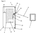
- FIG. 2 shows a switching device 1 according to the invention in a schematic representation.
- the switching device 1 of FIG. 2 includes a cabinet 2 with a cabinet housing 21.
- the cabinet housing 21 has a cabinet door 22.
- the control cabinet door is rotatably mounted on one side by means of a hinge 24.
- the control cabinet 2 can be closed by means of a closing device 25.
- the switching device 1 comprises a switching device 3, which is arranged in the control cabinet 2 and fixed by means of suitable fastening means 23 on the control cabinet housing 21.
- the switching device 3 may be a circuit breaker, a motor protection switch or the like.
- the switching device 3 is secured with locked cabinet 2 from unauthorized access.
- the switching device 3 is further equipped with a control element 31.
- the control element 31 has a shift lever 32 which serves for the manual operation of the switching device 3.
- the shift lever 32 protrudes partially out of the cabinet housing 21, so that the switching device. 3 Even with a closed cabinet 2 from outside the cabinet housing 21 is operated.
- the switching device 1 comprises an interface 4 for wireless communication, for example a Bluetooth interface.
- the interface 4 is in this case integrated with the associated electronics in the switching device 3. However, it is also generally possible to form the interface 4 separated from the switching device 3 but connectable.
- the interface 4 is intended to exchange data with the external device 7 wirelessly.
- the external receiving / transmitting device 7 may be, for example, a smartphone.
- the interface 4 has means for sending, receiving and for the electronic processing of the exchanged data.
- the interface 4 is suitable for processing information taken from the switching device 3, for example parameters of its operating state.
- the wireless communication interface 4 is connected to the antenna 5 by means of a connection cable 41.
- the antenna 5 is integrated in the control element 31, wherein the antenna 5 is partially inserted into a formed in the shift lever 32 cavity.
- the antenna 5 is intended to participate by emitting and / or receiving radio waves at the wireless communication between the interface 4 and the external receiving / transmitting device 7, which is indicated by the broken line 6 with double arrow.
- the antenna 5 is arranged such that it protrudes partially from the cabinet housing 21. This has the consequence that the purpose of data transmission from the antenna 5 in the direction of the receiving device 7 sent radio waves are not shielded from the cabinet housing 21, so that the communication can be largely trouble-free.
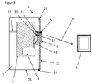
- FIG. 3 a further embodiment of the switching device 1 according to the invention is shown in a schematic representation.
- the FIG. 2 embodiment shown corresponds largely to in FIG. 2 illustrated, with the two embodiments differ by the formation of the control element 31.
- the control element 31 comprises the shift lever 32, which does not protrude from the cabinet housing 21 in the arrangement shown.
- the control element 31 additionally comprises an attachment 8, which is connected to the shift lever 32 via a suitable coupling (not shown).
- the attachment 8 in turn protrudes from the cabinet housing 21.
- the antenna 5 is integrated in the attachment 8 and arranged therein such that the antenna 5 partially also protrudes from the enclosure housing 21.
- the connection between the antenna 5 and the shift lever 31 is made via a connection line 81.
Landscapes
- Physics & Mathematics (AREA)
- Electromagnetism (AREA)
- Transceivers (AREA)
Description
- Die Erfindung betrifft eine Schaltvorrichtung mit einem Schaltschrank, einem Schaltgerät, das in dem Schaltschrank angeordnet ist, einer Schnittstelle zur drahtlosen Kommunikation sowie einer Antenne.
- Schaltgeräte können mit Schnittstellen zur drahtlosen Kommunikation ausgestattet sein, um Informationen über Betriebsparameter der Schaltgeräte drahtlos verfügbar zu machen. Ein zusätzlicher Vorteil solcher Anordnungen ergibt sich aus der Möglichkeit, ein derart ausgestaltetes Schaltgerät jeweils ortsunabhängig bedienbar zu gestalten. Zudem kann der Verdrahtungsaufwand der Schaltvorrichtung bei Verwendung drahtloser Kommunikationstechnik reduziert werden.
- Die Wechselwirkung der Funkübertragungssignale mit einem Schaltschrankgehäuse des Schaltschrankes kann sich jedoch in solchen Schaltvorrichtungen als problematisch erweisen.
- Die
DE 100 66 242 B4 offenbart beispielsweise einen kommunikationsfähigen Leistungsschalter. Die Kommunikationsfähigkeit wird dadurch erreicht, dass der Leistungsschalter eine Schnittstelle zur Funkdatenübertragung aufweist. Die Schnittstelle zur Funkdatenübertragung ist im Gehäuse des Leistungsschalters angeordnet. - Wird ein solcher Leistungsschalter im Schaltschrank angebracht, so kann die Funkdatenübertragung im Allgemeinen nicht durchgeführt werden, weil das meist aus Metall ausgeführte Schaltschrankgehäuse die Funksignale durch Abschirmung stört. Die von der innerhalb des Schaltschrankes angeordneten Schnittstelle zur Funkdatenübertragung gesendeten Funksignale werden an einer Innenwand des Schalschrankgehäuses größtenteils reflektiert und können so zur Datenübermittlung nicht verwendet werden.
- In der
DE 10 2004 002 330 A1 wird ein System zur Datenübertragung in Schaltanlagen beschrieben. Das System umfasst einen im Schaltschrank angeordneten Leistungsschalter. Der Leistungsschalter ist mittels eines Feldbusses mit einer Funkschnittstelle verbunden, wobei die Funkschnittstelle sich außerhalb des Schaltschrankes befindet. Zwischen der Funkschnittstelle und geeigneten Datenverarbeitungseinrichtungen, wie eine Notebook oder einem PDA mit einer eigenen Funkschnittstelle können auf diese Weise Daten, insbesondere Daten zur Überwachung des Leistungsschalters, leitungslos übertragen werden. - Durch die Anordnung der Funkschnittstelle außerhalb des Schaltschrankgehäuses kann die Abschirmung durch das Schaltschrankgehäuse vermieden werden. Anderseits steigt durch die notwendige Verdrahtung des Leistungsschalters mit der Funkschnittstelle der Material- und Planungsaufwand des Systems entsprechend nachteilig.
- Die Aufgabe der vorliegenden Erfindung ist es daher, eine Schaltvorrichtung der eingangs genannten Art vorzuschlagen, bei der eine Störung der drahtlosen Datenübertragung durch das Schaltschrankgehäuse bzw. der Verdrahtungsaufwand gegenüber den herkömmlichen Schaltvorrichtungen vermindert werden kann.
- Die
DE 20 2004 012 469 U1 , die als nächstliegender Stand der Technik angesehen wird, offenbart eine Schutzschalteranordnung mit einer Anzahl von Schutzschaltern, die ein Bedienelement aufweisen, das zum Auslösen des jeweiligen Schutzschalters durch eine Bedienfront hindurchgeführt und von deren Frontseite aus betätigbar ist, wobei jedem Schutzschalter ein ebenfalls von der Frontseite der Bedienfront aus zugängliches Koppelelement zum Austausch von Diagnose- und/oder Parametrierdaten zugeordnet ist. - Die Aufgabe wird durch die Schaltvorrichtung mit der Merkmalskombination des Patentanspruchs 1 gelöst. Die Patentansprüche 2 bis 6 stellen weitere vorteilhafte Ausführungsformen der Erfindung dar.
- Dementsprechend zeichnet sich die erfindungsgemäße Schaltvorrichtung dadurch aus, dass die Schnittstelle zur drahtlosen Kommunikation und die Antenne als zwei separate Teile ausgebildet sind und die Schnittstelle mit der Antenne verbunden ist, wobei die Schnittstelle innerhalb eines Gehäuses des Schaltgerätes angeordnet ist und die Antenne zumindest teilweise in ein durch das Schaltschrankgehäuse hindurchgreifendes Bedienelement des Schaltgerätes integriert ist. Insbesondere muss damit die Schnittstelle nicht über ein eigenes, darin integriertes Antennenelement verzügen. Zur Durchführung der drahtlosen Datenübermittlung wird die mit der Schnittstelle leitungsverbundene, in das Bedienelement integrierte Antenne verwendet.
- Im Sinne der vorliegenden Erfindung greift das Bedienelement durch das Schaltschrankgehäuse hindurch, wenn ein Teil des Bedienelements aus dem Schaltschrankgehäuse herausragt oder das Bedienelement in eine Öffnung im Schaltschrankgehäuse hineinragt.
- Durch eine geeignete Anordnung der Antenne in oder am Bedienelement, beispielsweise innerhalb eines Teilabschnitts des Bedienelements, der aus dem Schaltschrankgehäuse herausragt oder in die Öffnung im Schaltschrankgehäuse hineinragt, kann erreicht werden, dass die Störung der Funkübertragung durch unerwünschte Reflexionen am Schaltschrankgehäuse vermindert wird. Zugleich muss die Schaltvorrichtung nicht durch zusätzliche, miteinander zu verbindende Module erweitert werden, da die Antenne in bereits bestehende Teile integriert ist. Der Herstellungs- und Verdrahtungsaufwand ist somit gegenüber den herkömmlichen Schaltvorrichtungen vorteilhaft reduziert.
- Der Vorteil der Ausbildung der Schnittstelle zur drahtlosen Kommunikation und der zugehörigen Antenne als zwei separate, miteinander beispielsweise mittels eines geeigneten Verbindungskabels verbindbare Teile ergibt sich insbesondere daraus, dass die Antenne geringe Ausmaße und einen einfachen Aufbau aufweisen kann, so dass sie besonders gut in das Bedienelement eingebaut werden kann. Die Schnittstelle zur drahtlosen Kommunikation mit der darin enthaltenen Elektronik kann dann beispielsweise innerhalb eines Gehäuses des Schaltgeräts angeordnet und mit diesem einteilig ausgebildet sein.
- Gemäß einer Ausführungsform der Erfindung umfasst das Bedienelement einen Schalthebel. Der Schalthebel ist zu einer manuellen Betätigung bzw. Bedienung des Schalters vorgesehen. Der Schalthebel ragt zumindest teilweise aus dem Schaltschrankgehäuse aus, so dass er für einen sich außerhalb des Schaltschrankes befindenden Verwender zugänglich ist. Das Schaltschrankgehäuse weist in diesem Fall eine Öffnung auf, durch die der Schalthebel greifen kann. Die mit der Schnittstelle zur drahtlosen Kommunikation verbundene Antenne ist zumindest teilweise in den Schalthebel integriert.
- Gemäß einer weiteren Ausführungsform umfasst das Bedienelement einen Drehgriff bzw. einen Drehknopf. In diesem Fall ist die Antenne zumindest teilweise in den Drehgriff bzw. Drehknopf integriert.
- Des Weiteren kann das Bedienelement einen Fernantrieb umfassen, mittels dessen das Schaltgerät fernbedient werden kann. In diesem Fall kann die Antenne in den Fernantrieb integriert sein.
- In einigen Fällen ist der Schalthebel, der Drehgriff oder die anderen zum Bedienen des Schaltgerätes verwendete Teile derart aufgebaut bzw. das Schaltgerät derart im Schaltschrank angeordnet, dass das Bedienelement ohne ein Verlängerungsteil nicht durch das Schaltschrankgehäuse dringt. In solchen Fällen kann das Bedienelement außer dem Schalthebel einen Aufsatz umfassen, der beispielsweise mit dem Schalthebel, dem Drehgriff oder einem anderen Teil des Bedienelements verbunden, zum Beispiel auf den Schalthebel aufgesetzt und/oder festgeschraubt werden kann. Der Aufsatz stellt dann eine geeignete Verlängerung des Schalthebels dar. Der Aufsatz ist dabei derart ausgestaltet, dass er zumindest teilweise aus dem Schaltschrankgehäuse herausragt. Durch die geeignete Anordnung der Antenne in dem Aufsatz kann die bei der Datenübertragung störende Abschirmung der Funkwellen durch das Schaltschrankgehäuse vermieden werden.
- Ist die Antenne nicht im Schalthebel selbst integriert, dann kann der Schalthebel eine Kupplung aufweisen, die über das Verbindungskabel mit der Elektronik der Schnittstelle zur drahtlosen Kommunikation verbunden ist. Die Antenne kann dann als Aufsatz in diese Kupplung eingesteckt werden. Umfasst das Bedienelement statt des Schalthebels ein anderes Zubehörteil, wie zum Beispiel einen Drehgriff oder einen Fernantrieb, so kann der Aufsatz die Antenne beinhalten, die über eine Zuleitung ebenfalls an die Kupplung angeschlossen wird. Auch in diesen Fällen kann die Antenne zumindest teilweise außerhalb des Schaltschrankgehäuses angeordnet werden.
- Der Aufsatz kann darüber hinaus mit weiteren Funktionalitäten ausgestattet sein. Zum Beispiel kann der Aufsatz von außerhalb des Schaltschrankes sichtbare Anzeigeelemente umfassen. Auf diese Weise kann die Bedienung des Schaltgerätes weiter erleichtert werden.
- Es kann von Vorteil sein, wenn die Information über den Betriebszustand des Schaltgerätes auch dann noch vom Funkmodul zur Verfügung gestellt werden kann, wenn das Schaltgerät ausgelöst wird bzw. einer Störung unterliegt. Im Fall der Auslösung, beispielsweise Überlast-Auslösung, und/oder der Störung ist eine Energieversorgung des Schaltgerätes unter Umständen unterbrochen. Daher kann die Schnittstelle zur drahtlosen Kommunikation mit einer Energieversorgung ausgestattet werden, die von der Energieversorgung des Schaltgerätes unabhängig ist. Diese kann beispielsweise über einen eigenen GND/+24VDC-Anschluss an der Schnittstelle erfolgen. Fällt die Energieversorgung des Schaltgerätes aus, so kann die Schnittstelle über die eigene Energieversorgung weiter mit Strom versorgt werden. Ferner kann mittels der Schnittstelle in diesem Fall über die eigene zugeführte Energieversorgung das Schaltgerät weiter mit Energie versorgen und somit weiterhin Daten aus dem ausgeschalteten Schaltgerät abrufen.
- Die Schnittstelle zur drahtlosen Kommunikation kann ferner dazu geeignet ausgebildet sein, ein von einem Sender übermitteltes Steuersignal zu empfangen und/oder zu verarbeiten und/oder an das Schaltgerät weiter zu leiten. Damit kann die Schaltvorrichtung nicht nur drahtlos überwacht, sondern auch drahtlos gesteuert werden.
- Zur Kommunikation zwischen der Schnittstelle und dem Empfangsgerät/Sender kann Bluetooth oder ein entsprechend geeigneter weiterer Funkstandard verwendet werden. Auch kann die Schnittstelle mit der Antenne zur WLAN-Kommunikation geeignet ausgebildet sein. Das externe Empfangs-/Sendegerät kann beispielsweise durch einen Smartphone, einen Tablet-PC, Pager oder ein ähnliches Gerät mit der entsprechenden Programmierung realisiert sein.
- Die Antenne kann beispielsweise als Stab-Antenne ausgebildet sein. Sie kann die Richtcharakteristik eines Kugelstrahlers aufweisen, wobei die optimale Richtcharakteristik der Antenne im Allgemeinen von dem konkreten Einsatzbereich der Schaltvorrichtung abhängt.
- Im Folgenden wird die vorliegende Erfindung anhand der
Figuren 1 bis 3 weiter erläutert. - Figur 1:
- zeigt eine schematische Darstellung möglicher Anordnungen einer Antenne einer Schaltvorrichtung;
- Figur 2:
- zeigt eine Ausführungsform der erfindungsgemäßen Schaltvorrichtung in schematischer Darstellung;
- Figur 3:
- zeigt eine weitere Ausführungsform der erfindungsgemäßen Schaltvorrichtung in schematischer Darstellung.
- Im Einzelnen soll in der
Figur 1 durch eine schematische Darstellung möglicher Anordnungen einer Antenne 5A, 5B bezüglich des Schaltschrankgehäuses 21 eine der Erfindung zugrunde liegende Überlegung erläutert werden. - Über die Antenne 5A, 5B sollen Informationen von einem in
Figur 1 nicht dargestellten, mit der Antenne 5A, 5B verbundenen Schaltgerät an ein externes Empfangsgerät 7 übermittelt werden. - Die Antenne 5A ist in einem Innenbereich 92 eines Schaltschrankes angeordnet. Der Innenbereich 92 ist vom Außenbereich 91 des Schaltschrankes im Wesentlichen durch das Schaltschrankgehäuse 21 (in
Figur 1 teilweise dargestellt) getrennt. Das Empfangsgerät 7 befindet sich im Außenbereich 91. - Von der Antenne 5A ausgehend werden Funkwellen gesendet. Die Ausbreitungsrichtung der Funkwellen ist in
Figur 1 durch unterbrochene Linien 9A angedeutet. Wie aus der Darstellung derFigur 1 deutlich hervorgeht, werden die Funkwellen an dem Schaltschrankgehäuse 21 weitgehend reflektiert, so dass sie das Empfangsgerät 7 nicht erreichen können. In diesem Fall ist eine drahtlose Kommunikation zwischen dem mit der Antenne 5A verbundenen Schaltgerät und dem Empfangsgerät 7 erheblich gestört. - Die Antenne 5B ist in einer Öffnung 211 im Schaltschrankgehäuse 21 angeordnet, so dass die Antenne 5B teilweise aus dem Schaltschrankgehäuse 21 herausragt. Die von der Antenne 5B ausgehend gesendeten Funkwellen breiten sich insbesondere in die durch die unterbrochenen Linien 9B angedeuteten Richtungen aus. Die Funkwellen können hierbei das Empfangsgerät 7 erreichen, weil das Schaltschrankgehäuse 21 sich nicht als ein Hindernis zwischen der Antenne 5B und dem Empfangsgerät 7 erstreckt. Eine Datenübertragung zwischen der Antenne 5B und dem Empfangsgerät 7 ist in diesem Fall gut durchführbar.
-
Figur 2 zeigt eine erfindungsgemäße Schaltvorrichtung 1 in einer schematischen Darstellung. - Die Schaltvorrichtung 1 der
Figur 2 umfasst einen Schaltschrank 2 mit einem Schaltschrankgehäuse 21. Das Schaltschrankgehäuse 21 weist eine Schaltschranktür 22 auf. Die Schaltschranktür ist mittels eines Scharniers 24 einseitig drehbar montiert. Der Schaltschrank 2 kann mittels einer Schließvorrichtung 25 verschlossen werden. - Ferner umfasst die Schaltvorrichtung 1 ein Schaltgerät 3, das im Schaltschrank 2 angeordnet und mittels geeigneter Befestigungsmittel 23 am Schaltschrankgehäuse 21 befestigt ist. Das Schaltgerät 3 kann dabei ein Leistungsschalter, ein Motorschutzschalter oder dergleichen sein. Das Schaltgerät 3 ist bei verschlossenem Schaltschrank 2 vor unerlaubtem Zugriff gesichert. Das Schaltgerät 3 ist ferner mit einem Bedienelement 31 ausgestattet. Das Bedienelement 31 weist einen Schalthebel 32 auf, der zur manuellen Bedienung des Schaltgerätes 3 dient. Der Schalthebel 32 ragt teilweise aus dem Schaltschrankgehäuse 21 heraus, so dass das Schaltgerät 3 auch bei verschlossenem Schaltschrank 2 von außerhalb des Schaltschrankgehäuses 21 bedienbar ist.
- Des Weiteren umfasst die Schaltvorrichtung 1 eine Schnittstelle 4 zur drahtlosen Kommunikation, beispielsweise eine Bluetooth-Schnittstelle. Die Schnittstelle 4 ist hierbei mit der zugehörigen Elektronik in das Schaltgerät 3 integriert. Es ist aber im Allgemeinen ebenfalls möglich, die Schnittstelle 4 vom Schaltgerät 3 getrennt jedoch verbindbar auszubilden. Die Schnittstelle 4 ist dazu vorgesehen, Daten mit dem externen Gerät 7 drahtlos auszutauschen. Das externe Empfangs-/Sendegerät 7 kann beispielsweise ein Smartphone sein. Dazu verfügt die Schnittstelle 4 über Mittel zum Versenden, Empfangen und zur elektronischen Verarbeitung der ausgetauschten Daten. Ferner ist die Schnittstelle 4 geeignet, dem Schaltgerät 3 entnommene Informationen, beispielsweise Parameter dessen Betriebszustandes, zu verarbeiten.
- Die Schnittstelle 4 zur drahtlosen Kommunikation ist mittels eines Verbindungskabels 41 mit der Antenne 5 verbunden. Die Antenne 5 ist im Bedienelement 31 integriert, wobei die Antenne 5 teilweise in einen im Schalthebel 32 ausgebildeten Hohlraum eingesetzt ist. Die Antenne 5 ist dazu vorgesehen, durch Aussenden und/oder Empfangen von Funkwellen an der drahtlosen Kommunikation zwischen der Schnittstelle 4 und dem externen Empfangs-/Sendegerät 7 mitzuwirken, was mit der unterbrochen Linie 6 mit Doppelpfeil angedeutet ist.
- Die Antenne 5 ist derart angeordnet, dass sie teilweise aus dem Schaltschrankgehäuse 21 herausragt. Dies hat zur Folge, dass die zwecks Datenübertragung von der Antenne 5 aus in Richtung des Empfangsgerätes 7 gesandten Funkwellen nicht vom Schaltschrankgehäuse 21 abgeschirmt werden, so dass die Kommunikation weitgehend störungsfrei verlaufen kann.
- In
Figur 3 ist eine weitere Ausführungsform der erfindungsgemäßen Schaltvorrichtung 1 in einer schematischen Darstellung gezeigt. Die inFigur 2 gezeigte Ausführungsform entspricht weitgehend der inFigur 2 dargestellten, wobei sich die beiden Ausführungsbeispiele durch die Ausbildung des Bedienelements 31 unterscheiden. - In den
Figuren 2 und3 sind gleichen oder gleichartigen Teilen gleiche Bezugsziffern zugeordnet. Zur Vermeidung von Wiederholungen werden solche Teile ferner nicht mehrmals gesondert erläutert, sofern dies nicht zum Verständnis der Erfindung erforderlich ist. - In der in
Figur 3 dargestellten Ausführungsform der Schaltvorrichtung 1 umfasst das Bedienelement 31 den Schalthebel 32, der in der gezeigten Anordnung nicht aus dem Schaltschrankgehäuse 21 herausragt. In diesem Fall umfasst das Bedienelement 31 zusätzlich einen Aufsatz 8, der über eine geeignete Kupplung (nicht dargestellt) mit dem Schalthebel 32 verbunden ist. Der Aufsatz 8 ragt seinerseits aus dem Schaltschrankgehäuse 21 heraus. Die Antenne 5 ist in den Aufsatz 8 integriert und darin derart angeordnet, dass die Antenne 5 teilweise ebenfalls aus dem Schaltschrankgehäuse 21 herausragt. Die Verbindung zwischen der Antenne 5 und dem Schalthebel 31 ist über eine Verbindungsleitung 81 hergestellt. -
- 1
- Schaltvorrichtung
- 2
- Schaltschrank
- 21
- Schaltschrankgehäuse
- 211
- Öffnung
- 22
- Schaltschranktür
- 23
- Befestigungsmittel
- 24
- Scharnier
- 25
- Schließvorrichtung
- 3
- Schaltgerät
- 31
- Bedienelement
- 32
- Schalthebel
- 4
- Schnittstelle zur drahtlosen Kommunikation
- 41
- Verbindungskabel
- 5
- Antenne
- 5A,5B
- Antenne
- 6
- Linie
- 7
- externes Gerät
- 8
- Aufsatz
- 81
- Verbindungsleitung
- 9A
- Linie
- 9B
- Linie
- 91
- Außenbereich des Schaltschrankes
- 92
- Innenbereich des Schaltschrankes
Claims (6)
- Schaltvorrichtung (1), umfassend einen Schaltschrank (2) mit einem Schaltschrankgehäuse (21), ein Schaltgerät (3), das im Schaltschrank (2) angebracht ist, eine Schnittstelle (4) zur drahtlosen Kommunikation sowie eine Antenne (5), wobei die Schnittstelle (4) mit der Antenne (5) verbunden ist und die Antenne (5) zumindest teilweise in ein durch das Schaltschrankgehäuse (21) hindurchgreifendes Bedienelement (31) des Schaltgerätes (3) integriert ist, dadurch gekennzeichnet, dass die Schnittstelle (4) zur drahtlosen Kommunikation und die Antenne (5) als zwei separate Teile ausgebildet sind, wobei die Schnittstelle (4) innerhalb eines Gehäuses des Schaltgeräts (3) angeordnet ist.
- Schaltvorrichtung (1) nach Anspruch 1, dadurch gekennzeichnet, dass das Bedienelement (31) einen Schalthebel (32) umfasst, der Schalthebel (32) zumindest teilweise aus dem Schaltschrankgehäuse (2) herausragt, wobei die Antenne (5) zumindest teilweise in den Schalthebel (32) integriert ist.
- Schaltvorrichtung (1) nach Anspruch 1, dadurch gekennzeichnet, dass das Bedienelement (31) einen Drehgriff umfasst, wobei die Antenne (5) zumindest teilweise in den Drehgriff integriert ist.
- Schaltvorrichtung (1) nach einem der vorangehenden Ansprüche, dadurch gekennzeichnet, dass das Bedienelement (31) einen Fernantrieb umfasst, wobei die Antenne (5) zumindest teilweise in den Fernantrieb integriert ist.
- Schaltvorrichtung (1) nach einem der vorangehenden Ansprüche, dadurch gekennzeichnet, dass das Bedienelement (31) des Schaltgerätes (3) einen Aufsatz (8) umfasst, wobei der Aufsatz (8) zumindest teilweise aus dem Schaltschrankgehäuse (21) herausragt und die Antenne (5) zumindest teilweise in den Aufsatz (8) integriert ist.
- Schaltvorrichtung (1) nach einem der vorangehenden Ansprüche, dadurch gekennzeichnet, dass die Schnittstelle (4) zur drahtlosen Kommunikation über eine von der Energieversorgung des Schaltgerätes (3) unabhängige Energieversorgung verfügt.
Applications Claiming Priority (2)
| Application Number | Priority Date | Filing Date | Title |
|---|---|---|---|
| DE102012108845 | 2012-09-20 | ||
| PCT/EP2013/069430 WO2014044736A1 (de) | 2012-09-20 | 2013-09-19 | Schaltvorrichtung mit antennenanschluss für drahtlose kommunikation |
Publications (2)
| Publication Number | Publication Date |
|---|---|
| EP2898520A1 EP2898520A1 (de) | 2015-07-29 |
| EP2898520B1 true EP2898520B1 (de) | 2016-10-19 |
Family
ID=49212783
Family Applications (1)
| Application Number | Title | Priority Date | Filing Date |
|---|---|---|---|
| EP13763259.2A Not-in-force EP2898520B1 (de) | 2012-09-20 | 2013-09-19 | Schaltvorrichtung mit antennenanschluss für drahtlose kommunikation |
Country Status (2)
| Country | Link |
|---|---|
| EP (1) | EP2898520B1 (de) |
| WO (1) | WO2014044736A1 (de) |
Families Citing this family (5)
| Publication number | Priority date | Publication date | Assignee | Title |
|---|---|---|---|---|
| US9554480B2 (en) * | 2014-11-06 | 2017-01-24 | Schneider Electric USA, Inc. | Electrical enclosure operating mechanism housing an external antenna |
| CN104503324A (zh) * | 2014-12-18 | 2015-04-08 | 潘若愚 | 基于物联网的智能开关柜的控制方法 |
| CN107302190A (zh) * | 2017-07-24 | 2017-10-27 | 国网冀北电力有限公司唐山供电公司 | 开关柜保护测控装置操作把手远距离遥控装置及方法 |
| FR3076064B1 (fr) * | 2017-12-22 | 2019-12-20 | Hager Controls | Appareil auxiliaire pour appareillage de protection electrique |
| FR3076669B1 (fr) * | 2018-01-11 | 2020-10-09 | Schneider Electric Ind Sas | Appareil electrique communiquant sans fil et armoire electrique comprenant cet appareil electrique |
Family Cites Families (4)
| Publication number | Priority date | Publication date | Assignee | Title |
|---|---|---|---|---|
| DE10258919A1 (de) * | 2002-12-17 | 2004-07-01 | Abb Patent Gmbh | Vorrichtung, System und Verfahren zur Schaltstellungssignalisierung eines Schaltgerätes |
| DE202004012469U1 (de) * | 2004-08-10 | 2006-01-19 | Ellenberger & Poensgen Gmbh | Schutzschalteranordnung |
| US7623011B2 (en) * | 2005-10-12 | 2009-11-24 | R. J. Reynolds Tobacco Company | Device for remotely operating a circuit breaker apparatus and associated assembly and method |
| FR2971358B1 (fr) * | 2011-02-08 | 2013-07-26 | Schneider Electric Ind Sas | Dispositif de commutation sans-fil |
-
2013
- 2013-09-19 WO PCT/EP2013/069430 patent/WO2014044736A1/de not_active Ceased
- 2013-09-19 EP EP13763259.2A patent/EP2898520B1/de not_active Not-in-force
Also Published As
| Publication number | Publication date |
|---|---|
| EP2898520A1 (de) | 2015-07-29 |
| WO2014044736A1 (de) | 2014-03-27 |
Similar Documents
| Publication | Publication Date | Title |
|---|---|---|
| DE102005014137B4 (de) | Türverriegelungssystem | |
| DE69503354T2 (de) | Betätigungsvorrichtung für kraftfahrzeugtürschlösse | |
| WO2014044736A1 (de) | Schaltvorrichtung mit antennenanschluss für drahtlose kommunikation | |
| EP2646888B1 (de) | Gehäuse für ein computersystem und verwendung eines gehäuses | |
| EP2584577B1 (de) | Mehrpolige Schaltersicherungsanordnung für Sammelschienensysteme | |
| DE4008939A1 (de) | Elektronische rolladensteuerung mit steckbarem steuerteil | |
| DE112013000977T5 (de) | Automatische Türsteuereinrichtung und Türbetätigungsgerät | |
| EP1706851A2 (de) | Programmiergerät für sender-/empfängersysteme zur berührungslosen betätigung von türen und toren | |
| EP3353361A1 (de) | Betätigungseinrichtung für ein kraftfahrzeugschloss | |
| EP0878600B1 (de) | Elektromotorisch angetriebene Kippöffnungsvorrichtung für Fenster, Türen oder dergleichen | |
| EP1282238B1 (de) | Elektrogerät mit einer in ein Bedienelement integrierten drahtlosen Übertragungseinheit | |
| DE60004240T2 (de) | Elektrisch betriebener handschläger und rührer | |
| DE102012106923A1 (de) | Schaltvorrichtung mit Funkmodul und Deaktivierungsfunktion | |
| DE102019209521B4 (de) | Benutzerschnittstelleneinheit | |
| DE102015003337B4 (de) | Anzeige- und/oder Bedienvorrichtung für ein elektronisches Haushaltsgerät | |
| EP2933404B1 (de) | Türöffner mit rückmeldekontakt | |
| EP3374973B1 (de) | Fahrzeugtürgriff mit antennenanordnung | |
| DE29911232U1 (de) | Schließsystem für Türen mit Schließstellungsanzeige am Schlüssel | |
| EP0621617B1 (de) | Schalter mit Zusatzvorrichtung | |
| EP2037785B1 (de) | Handrührer mit sicherheitsverriegelung | |
| DE102009050230B4 (de) | Fahrzeugtür mit einer schlüssellosen Zugangskontrolleinrichtung | |
| DE102007015769B3 (de) | Griff zum mechanischen Betätigen eines Gegenstandes und Fensterelement | |
| WO2005098176A1 (de) | Mechatronischer schliesszylinder mit manuellem antriebselement | |
| DE202009015895U1 (de) | Signalkonverter für Tür- oder Schlossüberwachungssystem | |
| DE102013216361B4 (de) | Handfernbedienung zur Steuerung von elektrischen Verbrauchern |
Legal Events
| Date | Code | Title | Description |
|---|---|---|---|
| PUAI | Public reference made under article 153(3) epc to a published international application that has entered the european phase |
Free format text: ORIGINAL CODE: 0009012 |
|
| 17P | Request for examination filed |
Effective date: 20150130 |
|
| AK | Designated contracting states |
Kind code of ref document: A1 Designated state(s): AL AT BE BG CH CY CZ DE DK EE ES FI FR GB GR HR HU IE IS IT LI LT LU LV MC MK MT NL NO PL PT RO RS SE SI SK SM TR |
|
| AX | Request for extension of the european patent |
Extension state: BA ME |
|
| DAX | Request for extension of the european patent (deleted) | ||
| GRAP | Despatch of communication of intention to grant a patent |
Free format text: ORIGINAL CODE: EPIDOSNIGR1 |
|
| INTG | Intention to grant announced |
Effective date: 20160622 |
|
| GRAS | Grant fee paid |
Free format text: ORIGINAL CODE: EPIDOSNIGR3 |
|
| GRAA | (expected) grant |
Free format text: ORIGINAL CODE: 0009210 |
|
| AK | Designated contracting states |
Kind code of ref document: B1 Designated state(s): AL AT BE BG CH CY CZ DE DK EE ES FI FR GB GR HR HU IE IS IT LI LT LU LV MC MK MT NL NO PL PT RO RS SE SI SK SM TR |
|
| REG | Reference to a national code |
Ref country code: GB Ref legal event code: FG4D Free format text: NOT ENGLISH |
|
| REG | Reference to a national code |
Ref country code: CH Ref legal event code: EP |
|
| REG | Reference to a national code |
Ref country code: AT Ref legal event code: REF Ref document number: 838959 Country of ref document: AT Kind code of ref document: T Effective date: 20161115 |
|
| REG | Reference to a national code |
Ref country code: IE Ref legal event code: FG4D Free format text: LANGUAGE OF EP DOCUMENT: GERMAN |
|
| REG | Reference to a national code |
Ref country code: DE Ref legal event code: R096 Ref document number: 502013005063 Country of ref document: DE |
|
| REG | Reference to a national code |
Ref country code: NL Ref legal event code: MP Effective date: 20161019 |
|
| REG | Reference to a national code |
Ref country code: LT Ref legal event code: MG4D |
|
| PG25 | Lapsed in a contracting state [announced via postgrant information from national office to epo] |
Ref country code: LV Free format text: LAPSE BECAUSE OF FAILURE TO SUBMIT A TRANSLATION OF THE DESCRIPTION OR TO PAY THE FEE WITHIN THE PRESCRIBED TIME-LIMIT Effective date: 20161019 |
|
| PG25 | Lapsed in a contracting state [announced via postgrant information from national office to epo] |
Ref country code: GR Free format text: LAPSE BECAUSE OF FAILURE TO SUBMIT A TRANSLATION OF THE DESCRIPTION OR TO PAY THE FEE WITHIN THE PRESCRIBED TIME-LIMIT Effective date: 20170120 Ref country code: SE Free format text: LAPSE BECAUSE OF FAILURE TO SUBMIT A TRANSLATION OF THE DESCRIPTION OR TO PAY THE FEE WITHIN THE PRESCRIBED TIME-LIMIT Effective date: 20161019 Ref country code: NO Free format text: LAPSE BECAUSE OF FAILURE TO SUBMIT A TRANSLATION OF THE DESCRIPTION OR TO PAY THE FEE WITHIN THE PRESCRIBED TIME-LIMIT Effective date: 20170119 Ref country code: LT Free format text: LAPSE BECAUSE OF FAILURE TO SUBMIT A TRANSLATION OF THE DESCRIPTION OR TO PAY THE FEE WITHIN THE PRESCRIBED TIME-LIMIT Effective date: 20161019 |
|
| PG25 | Lapsed in a contracting state [announced via postgrant information from national office to epo] |
Ref country code: RS Free format text: LAPSE BECAUSE OF FAILURE TO SUBMIT A TRANSLATION OF THE DESCRIPTION OR TO PAY THE FEE WITHIN THE PRESCRIBED TIME-LIMIT Effective date: 20161019 Ref country code: PL Free format text: LAPSE BECAUSE OF FAILURE TO SUBMIT A TRANSLATION OF THE DESCRIPTION OR TO PAY THE FEE WITHIN THE PRESCRIBED TIME-LIMIT Effective date: 20161019 Ref country code: HR Free format text: LAPSE BECAUSE OF FAILURE TO SUBMIT A TRANSLATION OF THE DESCRIPTION OR TO PAY THE FEE WITHIN THE PRESCRIBED TIME-LIMIT Effective date: 20161019 Ref country code: NL Free format text: LAPSE BECAUSE OF FAILURE TO SUBMIT A TRANSLATION OF THE DESCRIPTION OR TO PAY THE FEE WITHIN THE PRESCRIBED TIME-LIMIT Effective date: 20161019 Ref country code: FI Free format text: LAPSE BECAUSE OF FAILURE TO SUBMIT A TRANSLATION OF THE DESCRIPTION OR TO PAY THE FEE WITHIN THE PRESCRIBED TIME-LIMIT Effective date: 20161019 Ref country code: IS Free format text: LAPSE BECAUSE OF FAILURE TO SUBMIT A TRANSLATION OF THE DESCRIPTION OR TO PAY THE FEE WITHIN THE PRESCRIBED TIME-LIMIT Effective date: 20170219 Ref country code: ES Free format text: LAPSE BECAUSE OF FAILURE TO SUBMIT A TRANSLATION OF THE DESCRIPTION OR TO PAY THE FEE WITHIN THE PRESCRIBED TIME-LIMIT Effective date: 20161019 Ref country code: PT Free format text: LAPSE BECAUSE OF FAILURE TO SUBMIT A TRANSLATION OF THE DESCRIPTION OR TO PAY THE FEE WITHIN THE PRESCRIBED TIME-LIMIT Effective date: 20170220 |
|
| REG | Reference to a national code |
Ref country code: DE Ref legal event code: R097 Ref document number: 502013005063 Country of ref document: DE |
|
| PG25 | Lapsed in a contracting state [announced via postgrant information from national office to epo] |
Ref country code: DK Free format text: LAPSE BECAUSE OF FAILURE TO SUBMIT A TRANSLATION OF THE DESCRIPTION OR TO PAY THE FEE WITHIN THE PRESCRIBED TIME-LIMIT Effective date: 20161019 Ref country code: EE Free format text: LAPSE BECAUSE OF FAILURE TO SUBMIT A TRANSLATION OF THE DESCRIPTION OR TO PAY THE FEE WITHIN THE PRESCRIBED TIME-LIMIT Effective date: 20161019 Ref country code: RO Free format text: LAPSE BECAUSE OF FAILURE TO SUBMIT A TRANSLATION OF THE DESCRIPTION OR TO PAY THE FEE WITHIN THE PRESCRIBED TIME-LIMIT Effective date: 20161019 Ref country code: SK Free format text: LAPSE BECAUSE OF FAILURE TO SUBMIT A TRANSLATION OF THE DESCRIPTION OR TO PAY THE FEE WITHIN THE PRESCRIBED TIME-LIMIT Effective date: 20161019 Ref country code: CZ Free format text: LAPSE BECAUSE OF FAILURE TO SUBMIT A TRANSLATION OF THE DESCRIPTION OR TO PAY THE FEE WITHIN THE PRESCRIBED TIME-LIMIT Effective date: 20161019 |
|
| PLBE | No opposition filed within time limit |
Free format text: ORIGINAL CODE: 0009261 |
|
| STAA | Information on the status of an ep patent application or granted ep patent |
Free format text: STATUS: NO OPPOSITION FILED WITHIN TIME LIMIT |
|
| PG25 | Lapsed in a contracting state [announced via postgrant information from national office to epo] |
Ref country code: BG Free format text: LAPSE BECAUSE OF FAILURE TO SUBMIT A TRANSLATION OF THE DESCRIPTION OR TO PAY THE FEE WITHIN THE PRESCRIBED TIME-LIMIT Effective date: 20170119 Ref country code: IT Free format text: LAPSE BECAUSE OF FAILURE TO SUBMIT A TRANSLATION OF THE DESCRIPTION OR TO PAY THE FEE WITHIN THE PRESCRIBED TIME-LIMIT Effective date: 20161019 Ref country code: SM Free format text: LAPSE BECAUSE OF FAILURE TO SUBMIT A TRANSLATION OF THE DESCRIPTION OR TO PAY THE FEE WITHIN THE PRESCRIBED TIME-LIMIT Effective date: 20161019 |
|
| 26N | No opposition filed |
Effective date: 20170720 |
|
| PG25 | Lapsed in a contracting state [announced via postgrant information from national office to epo] |
Ref country code: SI Free format text: LAPSE BECAUSE OF FAILURE TO SUBMIT A TRANSLATION OF THE DESCRIPTION OR TO PAY THE FEE WITHIN THE PRESCRIBED TIME-LIMIT Effective date: 20161019 |
|
| REG | Reference to a national code |
Ref country code: CH Ref legal event code: PL |
|
| GBPC | Gb: european patent ceased through non-payment of renewal fee |
Effective date: 20170919 |
|
| PG25 | Lapsed in a contracting state [announced via postgrant information from national office to epo] |
Ref country code: MC Free format text: LAPSE BECAUSE OF FAILURE TO SUBMIT A TRANSLATION OF THE DESCRIPTION OR TO PAY THE FEE WITHIN THE PRESCRIBED TIME-LIMIT Effective date: 20161019 |
|
| REG | Reference to a national code |
Ref country code: IE Ref legal event code: MM4A |
|
| REG | Reference to a national code |
Ref country code: BE Ref legal event code: MM Effective date: 20170930 |
|
| PG25 | Lapsed in a contracting state [announced via postgrant information from national office to epo] |
Ref country code: LU Free format text: LAPSE BECAUSE OF NON-PAYMENT OF DUE FEES Effective date: 20170919 |
|
| REG | Reference to a national code |
Ref country code: FR Ref legal event code: ST Effective date: 20180531 |
|
| PG25 | Lapsed in a contracting state [announced via postgrant information from national office to epo] |
Ref country code: GB Free format text: LAPSE BECAUSE OF NON-PAYMENT OF DUE FEES Effective date: 20170919 Ref country code: CH Free format text: LAPSE BECAUSE OF NON-PAYMENT OF DUE FEES Effective date: 20170930 Ref country code: LI Free format text: LAPSE BECAUSE OF NON-PAYMENT OF DUE FEES Effective date: 20170930 Ref country code: IE Free format text: LAPSE BECAUSE OF NON-PAYMENT OF DUE FEES Effective date: 20170919 |
|
| PG25 | Lapsed in a contracting state [announced via postgrant information from national office to epo] |
Ref country code: BE Free format text: LAPSE BECAUSE OF NON-PAYMENT OF DUE FEES Effective date: 20170930 Ref country code: FR Free format text: LAPSE BECAUSE OF NON-PAYMENT OF DUE FEES Effective date: 20171002 |
|
| PG25 | Lapsed in a contracting state [announced via postgrant information from national office to epo] |
Ref country code: MT Free format text: LAPSE BECAUSE OF FAILURE TO SUBMIT A TRANSLATION OF THE DESCRIPTION OR TO PAY THE FEE WITHIN THE PRESCRIBED TIME-LIMIT Effective date: 20161019 |
|
| PGFP | Annual fee paid to national office [announced via postgrant information from national office to epo] |
Ref country code: DE Payment date: 20180821 Year of fee payment: 6 |
|
| REG | Reference to a national code |
Ref country code: DE Ref legal event code: R081 Ref document number: 502013005063 Country of ref document: DE Owner name: EATON INTELLIGENT POWER LIMITED, IE Free format text: FORMER OWNER: EATON ELECTRICAL IP GMBH & CO. KG, 12529 SCHOENEFELD, DE |
|
| PG25 | Lapsed in a contracting state [announced via postgrant information from national office to epo] |
Ref country code: HU Free format text: LAPSE BECAUSE OF FAILURE TO SUBMIT A TRANSLATION OF THE DESCRIPTION OR TO PAY THE FEE WITHIN THE PRESCRIBED TIME-LIMIT; INVALID AB INITIO Effective date: 20130919 |
|
| PG25 | Lapsed in a contracting state [announced via postgrant information from national office to epo] |
Ref country code: CY Free format text: LAPSE BECAUSE OF FAILURE TO SUBMIT A TRANSLATION OF THE DESCRIPTION OR TO PAY THE FEE WITHIN THE PRESCRIBED TIME-LIMIT Effective date: 20161019 |
|
| REG | Reference to a national code |
Ref country code: AT Ref legal event code: MM01 Ref document number: 838959 Country of ref document: AT Kind code of ref document: T Effective date: 20180919 |
|
| PG25 | Lapsed in a contracting state [announced via postgrant information from national office to epo] |
Ref country code: MK Free format text: LAPSE BECAUSE OF FAILURE TO SUBMIT A TRANSLATION OF THE DESCRIPTION OR TO PAY THE FEE WITHIN THE PRESCRIBED TIME-LIMIT Effective date: 20161019 |
|
| PG25 | Lapsed in a contracting state [announced via postgrant information from national office to epo] |
Ref country code: AT Free format text: LAPSE BECAUSE OF NON-PAYMENT OF DUE FEES Effective date: 20180919 |
|
| PG25 | Lapsed in a contracting state [announced via postgrant information from national office to epo] |
Ref country code: TR Free format text: LAPSE BECAUSE OF FAILURE TO SUBMIT A TRANSLATION OF THE DESCRIPTION OR TO PAY THE FEE WITHIN THE PRESCRIBED TIME-LIMIT Effective date: 20161019 |
|
| REG | Reference to a national code |
Ref country code: DE Ref legal event code: R119 Ref document number: 502013005063 Country of ref document: DE |
|
| PG25 | Lapsed in a contracting state [announced via postgrant information from national office to epo] |
Ref country code: AL Free format text: LAPSE BECAUSE OF FAILURE TO SUBMIT A TRANSLATION OF THE DESCRIPTION OR TO PAY THE FEE WITHIN THE PRESCRIBED TIME-LIMIT Effective date: 20161019 Ref country code: DE Free format text: LAPSE BECAUSE OF NON-PAYMENT OF DUE FEES Effective date: 20200401 |