EP2898322B1 - Verfahren und vorrichtung zur verbesserung der saft-analyse bei unregelmässiger lokaler messdichte - Google Patents
Verfahren und vorrichtung zur verbesserung der saft-analyse bei unregelmässiger lokaler messdichte Download PDFInfo
- Publication number
- EP2898322B1 EP2898322B1 EP13786194.4A EP13786194A EP2898322B1 EP 2898322 B1 EP2898322 B1 EP 2898322B1 EP 13786194 A EP13786194 A EP 13786194A EP 2898322 B1 EP2898322 B1 EP 2898322B1
- Authority
- EP
- European Patent Office
- Prior art keywords
- measurement
- echo signals
- density
- data processing
- positions
- Prior art date
- Legal status (The legal status is an assumption and is not a legal conclusion. Google has not performed a legal analysis and makes no representation as to the accuracy of the status listed.)
- Active
Links
- 238000005259 measurement Methods 0.000 title claims description 112
- 238000000034 method Methods 0.000 title claims description 27
- 230000001788 irregular Effects 0.000 title 1
- 238000012360 testing method Methods 0.000 claims description 142
- 238000012545 processing Methods 0.000 claims description 24
- 239000000523 sample Substances 0.000 claims description 20
- 238000011156 evaluation Methods 0.000 claims description 17
- 238000012935 Averaging Methods 0.000 claims description 8
- 238000004519 manufacturing process Methods 0.000 claims description 3
- 238000002604 ultrasonography Methods 0.000 description 15
- 238000001514 detection method Methods 0.000 description 13
- 230000007547 defect Effects 0.000 description 6
- 230000033001 locomotion Effects 0.000 description 5
- 230000003287 optical effect Effects 0.000 description 4
- 238000009826 distribution Methods 0.000 description 2
- 238000007689 inspection Methods 0.000 description 2
- 230000004807 localization Effects 0.000 description 2
- 238000009659 non-destructive testing Methods 0.000 description 2
- 238000006073 displacement reaction Methods 0.000 description 1
- 230000004886 head movement Effects 0.000 description 1
- 238000003384 imaging method Methods 0.000 description 1
- 238000013507 mapping Methods 0.000 description 1
- 238000000926 separation method Methods 0.000 description 1
- 238000010998 test method Methods 0.000 description 1
Images

Classifications
-
- G—PHYSICS
- G01—MEASURING; TESTING
- G01S—RADIO DIRECTION-FINDING; RADIO NAVIGATION; DETERMINING DISTANCE OR VELOCITY BY USE OF RADIO WAVES; LOCATING OR PRESENCE-DETECTING BY USE OF THE REFLECTION OR RERADIATION OF RADIO WAVES; ANALOGOUS ARRANGEMENTS USING OTHER WAVES
- G01S15/00—Systems using the reflection or reradiation of acoustic waves, e.g. sonar systems
- G01S15/88—Sonar systems specially adapted for specific applications
- G01S15/89—Sonar systems specially adapted for specific applications for mapping or imaging
- G01S15/8906—Short-range imaging systems; Acoustic microscope systems using pulse-echo techniques
- G01S15/8997—Short-range imaging systems; Acoustic microscope systems using pulse-echo techniques using synthetic aperture techniques
-
- G—PHYSICS
- G01—MEASURING; TESTING
- G01N—INVESTIGATING OR ANALYSING MATERIALS BY DETERMINING THEIR CHEMICAL OR PHYSICAL PROPERTIES
- G01N29/00—Investigating or analysing materials by the use of ultrasonic, sonic or infrasonic waves; Visualisation of the interior of objects by transmitting ultrasonic or sonic waves through the object
- G01N29/04—Analysing solids
- G01N29/06—Visualisation of the interior, e.g. acoustic microscopy
- G01N29/0609—Display arrangements, e.g. colour displays
- G01N29/0645—Display representation or displayed parameters, e.g. A-, B- or C-Scan
-
- G—PHYSICS
- G01—MEASURING; TESTING
- G01N—INVESTIGATING OR ANALYSING MATERIALS BY DETERMINING THEIR CHEMICAL OR PHYSICAL PROPERTIES
- G01N29/00—Investigating or analysing materials by the use of ultrasonic, sonic or infrasonic waves; Visualisation of the interior of objects by transmitting ultrasonic or sonic waves through the object
- G01N29/04—Analysing solids
- G01N29/06—Visualisation of the interior, e.g. acoustic microscopy
- G01N29/0654—Imaging
- G01N29/0672—Imaging by acoustic tomography
-
- G—PHYSICS
- G01—MEASURING; TESTING
- G01N—INVESTIGATING OR ANALYSING MATERIALS BY DETERMINING THEIR CHEMICAL OR PHYSICAL PROPERTIES
- G01N29/00—Investigating or analysing materials by the use of ultrasonic, sonic or infrasonic waves; Visualisation of the interior of objects by transmitting ultrasonic or sonic waves through the object
- G01N29/04—Analysing solids
- G01N29/06—Visualisation of the interior, e.g. acoustic microscopy
- G01N29/0654—Imaging
- G01N29/069—Defect imaging, localisation and sizing using, e.g. time of flight diffraction [TOFD], synthetic aperture focusing technique [SAFT], Amplituden-Laufzeit-Ortskurven [ALOK] technique
-
- G—PHYSICS
- G01—MEASURING; TESTING
- G01N—INVESTIGATING OR ANALYSING MATERIALS BY DETERMINING THEIR CHEMICAL OR PHYSICAL PROPERTIES
- G01N29/00—Investigating or analysing materials by the use of ultrasonic, sonic or infrasonic waves; Visualisation of the interior of objects by transmitting ultrasonic or sonic waves through the object
- G01N29/22—Details, e.g. general constructional or apparatus details
- G01N29/225—Supports, positioning or alignment in moving situation
- G01N29/226—Handheld or portable devices
-
- G—PHYSICS
- G01—MEASURING; TESTING
- G01N—INVESTIGATING OR ANALYSING MATERIALS BY DETERMINING THEIR CHEMICAL OR PHYSICAL PROPERTIES
- G01N29/00—Investigating or analysing materials by the use of ultrasonic, sonic or infrasonic waves; Visualisation of the interior of objects by transmitting ultrasonic or sonic waves through the object
- G01N29/22—Details, e.g. general constructional or apparatus details
- G01N29/24—Probes
-
- G—PHYSICS
- G01—MEASURING; TESTING
- G01N—INVESTIGATING OR ANALYSING MATERIALS BY DETERMINING THEIR CHEMICAL OR PHYSICAL PROPERTIES
- G01N29/00—Investigating or analysing materials by the use of ultrasonic, sonic or infrasonic waves; Visualisation of the interior of objects by transmitting ultrasonic or sonic waves through the object
- G01N29/22—Details, e.g. general constructional or apparatus details
- G01N29/26—Arrangements for orientation or scanning by relative movement of the head and the sensor
- G01N29/262—Arrangements for orientation or scanning by relative movement of the head and the sensor by electronic orientation or focusing, e.g. with phased arrays
-
- G—PHYSICS
- G01—MEASURING; TESTING
- G01N—INVESTIGATING OR ANALYSING MATERIALS BY DETERMINING THEIR CHEMICAL OR PHYSICAL PROPERTIES
- G01N29/00—Investigating or analysing materials by the use of ultrasonic, sonic or infrasonic waves; Visualisation of the interior of objects by transmitting ultrasonic or sonic waves through the object
- G01N29/22—Details, e.g. general constructional or apparatus details
- G01N29/26—Arrangements for orientation or scanning by relative movement of the head and the sensor
- G01N29/265—Arrangements for orientation or scanning by relative movement of the head and the sensor by moving the sensor relative to a stationary material
-
- G—PHYSICS
- G01—MEASURING; TESTING
- G01N—INVESTIGATING OR ANALYSING MATERIALS BY DETERMINING THEIR CHEMICAL OR PHYSICAL PROPERTIES
- G01N29/00—Investigating or analysing materials by the use of ultrasonic, sonic or infrasonic waves; Visualisation of the interior of objects by transmitting ultrasonic or sonic waves through the object
- G01N29/34—Generating the ultrasonic, sonic or infrasonic waves, e.g. electronic circuits specially adapted therefor
- G01N29/341—Generating the ultrasonic, sonic or infrasonic waves, e.g. electronic circuits specially adapted therefor with time characteristics
- G01N29/343—Generating the ultrasonic, sonic or infrasonic waves, e.g. electronic circuits specially adapted therefor with time characteristics pulse waves, e.g. particular sequence of pulses, bursts
-
- G—PHYSICS
- G01—MEASURING; TESTING
- G01N—INVESTIGATING OR ANALYSING MATERIALS BY DETERMINING THEIR CHEMICAL OR PHYSICAL PROPERTIES
- G01N29/00—Investigating or analysing materials by the use of ultrasonic, sonic or infrasonic waves; Visualisation of the interior of objects by transmitting ultrasonic or sonic waves through the object
- G01N29/44—Processing the detected response signal, e.g. electronic circuits specially adapted therefor
- G01N29/4463—Signal correction, e.g. distance amplitude correction [DAC], distance gain size [DGS], noise filtering
-
- G—PHYSICS
- G01—MEASURING; TESTING
- G01N—INVESTIGATING OR ANALYSING MATERIALS BY DETERMINING THEIR CHEMICAL OR PHYSICAL PROPERTIES
- G01N29/00—Investigating or analysing materials by the use of ultrasonic, sonic or infrasonic waves; Visualisation of the interior of objects by transmitting ultrasonic or sonic waves through the object
- G01N29/44—Processing the detected response signal, e.g. electronic circuits specially adapted therefor
- G01N29/449—Statistical methods not provided for in G01N29/4409, e.g. averaging, smoothing and interpolation
-
- G—PHYSICS
- G01—MEASURING; TESTING
- G01S—RADIO DIRECTION-FINDING; RADIO NAVIGATION; DETERMINING DISTANCE OR VELOCITY BY USE OF RADIO WAVES; LOCATING OR PRESENCE-DETECTING BY USE OF THE REFLECTION OR RERADIATION OF RADIO WAVES; ANALOGOUS ARRANGEMENTS USING OTHER WAVES
- G01S15/00—Systems using the reflection or reradiation of acoustic waves, e.g. sonar systems
- G01S15/88—Sonar systems specially adapted for specific applications
- G01S15/89—Sonar systems specially adapted for specific applications for mapping or imaging
- G01S15/8906—Short-range imaging systems; Acoustic microscope systems using pulse-echo techniques
- G01S15/8934—Short-range imaging systems; Acoustic microscope systems using pulse-echo techniques using a dynamic transducer configuration
- G01S15/8936—Short-range imaging systems; Acoustic microscope systems using pulse-echo techniques using a dynamic transducer configuration using transducers mounted for mechanical movement in three dimensions
-
- G—PHYSICS
- G01—MEASURING; TESTING
- G01S—RADIO DIRECTION-FINDING; RADIO NAVIGATION; DETERMINING DISTANCE OR VELOCITY BY USE OF RADIO WAVES; LOCATING OR PRESENCE-DETECTING BY USE OF THE REFLECTION OR RERADIATION OF RADIO WAVES; ANALOGOUS ARRANGEMENTS USING OTHER WAVES
- G01S7/00—Details of systems according to groups G01S13/00, G01S15/00, G01S17/00
- G01S7/52—Details of systems according to groups G01S13/00, G01S15/00, G01S17/00 of systems according to group G01S15/00
- G01S7/52017—Details of systems according to groups G01S13/00, G01S15/00, G01S17/00 of systems according to group G01S15/00 particularly adapted to short-range imaging
- G01S7/5205—Means for monitoring or calibrating
-
- G—PHYSICS
- G01—MEASURING; TESTING
- G01N—INVESTIGATING OR ANALYSING MATERIALS BY DETERMINING THEIR CHEMICAL OR PHYSICAL PROPERTIES
- G01N2291/00—Indexing codes associated with group G01N29/00
- G01N2291/04—Wave modes and trajectories
- G01N2291/044—Internal reflections (echoes), e.g. on walls or defects
Definitions
- the invention relates to a method and a device for ultrasonic testing of a test object specified in the preambles of the independent claims Art.
- a variety of ultrasonic testing methods are known.
- the analysis technique SAFT Synthetic Aperture Focusing Technique
- the inspection is carried out in the same way as a conventional ultrasonic test, but the data is recorded without rectification.
- amplitude sums are determined from a multiplicity of measurement signals for respective small volume elements, which are also referred to as so-called voxels.
- the ultrasonic test can be used with the aid of the SAFT analysis, for example, in a manual movement of the ultrasound pulses emitting and the corresponding echo signals receiving test head.
- SAFT test is for example in the DE 10 2013 200974.7 described.
- test objects can be scanned not only mechanically but also electronically, ie by performing a kind of electronic displacement of the active zone of the test head several measurements are carried out in a defined grid.
- data taken with the same electronic scan can be evaluated using SAFT analysis. This works both with the probe still moving and with the probe moving during the electronic scan when the exact transmit and receive position and insonification angle and focusing at the time of reconstruction are known.
- the DE 10 2009 050 160 A1 discloses a method and an apparatus for ultrasonic testing of a test object, in which ultrasonic waves are coupled via a surface of the test object in the test object.
- artefacts or measurement errors generated during the manual free guidance of a test head should be effectively reduced or removed during the SAFT evaluation.
- the object is achieved by a method according to claim 1 and a device according to claim 10.
- the method according to the invention for ultrasonic testing of a test object comprises the following steps: moving a test object along a test object surface and emitting ultrasound pulses into the test object by means of the test head; Receiving respective echo signals corresponding to the emitted ultrasound pulses by means of the test head; Generating an image of a predetermined test area of the test object based on a superimposition and averaging of amplitude values of the received echo signals by means of a data processing device.
- the method according to the invention for ultrasound testing of a test object comprises the steps required for a SAFT analysis, whereby additionally the respective positions of the test head during emission of the ultrasound signals and / or upon receipt of the corresponding echo signals are detected by means of a detection device and the respectively detected positions of the test head be taken into account when generating the mapping of the test area of the test object.
- manually moving a freely guided test head along a test object surface and within a measuring area consisting of partial areas is carried out by emitting ultrasonic pulses into the test object by means of the test head and receiving respective ultrasound pulses corresponding to the emitted ones Echo signals by means of the test head; Generating an image of a predetermined test area of the test object based on a superimposition and averaging of amplitude values of the received echo signals by means of a data processing device; Detecting a respective measuring position of the test head by means of a detection device; Taking into account the respectively detected measuring positions of the test head when generating the image of the test area of the test object; Determining an evaluation variable for detecting irregularities with respect to the respectively detected measurement positions within the measurement surface by means of the data processing device; by means of the evaluation variable, weighting each echo signal received for the respectively acquired measurement position to generate the image (5) by means of the data processing device in such a way that the irregularities are compensated.
- an apparatus for ultrasonic testing of a test object comprising: a test head which is manually freely movable along a test object surface and within a measurement area consisting of partial areas and by emitting ultrasound pulses into the test object and receiving respective echo signals corresponding to the emitted ultrasound pulses measures; a detection device that detects a respective measurement position of the test head; a data processing device that generates an image of a predetermined test area of the test object based on a superimposition and averaging of amplitude values of the received echo signals; and takes into account the respectively detected measurement positions of the test head when generating the image of the test area of the test object; wherein the data processing device is weighted such that the irregularities are compensated for by means of at least one evaluation variable for detecting irregularities with respect to the respectively detected measurement positions within the measurement surface of each echo signal received for the respective acquired measurement position.
- a test head in the case of a manual guidance, a test head is not precisely guided and measurements are carried out in a fluctuating grid or along crooked paths, so that artifacts are generated in this way.
- an echo signal at each measuring point should not be used directly for the SAFT evaluation. Echo signals should be selected and / or weighted according to a density and distribution of measuring points on a measuring surface in such a way that all parts of the measuring surface contribute as evenly as possible to each reconstructed voxel or test area of the test object. The prerequisite is that reliable position information is available for each individual measurement.
- the solution according to the invention results in an improved SAFT evaluation of tests with freehand guided test head. Similarly, artifacts can be effectively reduced and a signal-to-noise ratio SNR of the SAFT result effectively increased. It can also be compensated for irregularities whose causes are not in the freehand guidance of the probe, but caused for example by Ankoppelschwankache.
- a local measurement density is determined as the evaluation variable, and a weighting takes place in such a way that echo signals from measurement positions with a large local measurement density are weighted less heavily than echo signals from measurement positions with average or small measurement density.
- the local measurement density can be determined from a respective number of detected measurement positions per unit area of the measurement area or per unit length of at least one scan line of the measurement area.
- a weighting can be carried out such that echo signals of measuring positions are weighted in inverse proportion to the local measuring density.
- the local measurement density can be determined by summing all reciprocals of all distances of a detected measurement position to all other detected measurement positions within a predetermined first radius.
- a weighting can be carried out in such a way that echo signals from measurement positions having a relatively largest local measurement density are weighted to zero.
- the local measurement density can again be determined within a predetermined second radius about the measurement positions whose echo signals were weighted zero.
- a repeated omission with zero-weighted measurement positions and renewed determination of the local measurement density can take place as long as a predetermined minimum measurement density is not undershot.
- a determination of a homogeneous contribution of all subareas of the measurement surface as evaluation variable and weights can take place in such a way that the echo signals from measurement positions contribute as uniformly as possible to the imaging.
- detection of the respective measuring position of the test head can take place when the ultrasound signal is emitted and / or when the corresponding echo signal is received.
- Fig. 1 shows a first embodiment of a device according to the invention, wherein the position of a test head 3 is measured on a surface 2 of a test object 1 during the duration of the test.
- the measurement of the respective position takes place within comparatively short intervals and with a defined time reference relative to the ultrasound pulses emitted for inspection of the test object 1.
- the position measurement is preferably carried out by means of a detection device 9 in each case when an ultrasonic pulse is emitted.
- a position measurement can also be carried out in each case if the echo signal corresponding to the emitted ultrasound pulse is received.
- a respective current position of the probe 3 preferably at the time of each emission of the ultrasonic pulse, and in the SAFT analysis to determine a distance between a voxel to be reconstructed and the actual Used measuring position.
- the device according to the invention and the method for ultrasound testing of a test object should be applied with the aid of the SAFT analysis on moving, in particular freehand, test head 3.
- the Probe 3 are moved manually along the für Testober
- the test head 3 can be guided freely on the test object surface 2 in the method according to the invention.
- the localization of defects within the test object 1 is considerably improved by the method, whereby individual defects are better distinguished from one another and the signal-to-noise ratio is improved, in particular in the case of a manual, in particular freehand, test.
- test results 5 of the test area of the test object 1 an improved resolution of group displays, ie of closely spaced individual displays that could not be separated without a SAFT analysis and would therefore be evaluated as a larger display, and in particular an improved detection of small defects.
- small defects are meant defects with a dimension which are small in relation to the wavelength of the ultrasonic pulses used.
- the test results 5, which are achieved with the method according to the invention can be interpreted particularly intuitively by referencing to a three-dimensional digital model of the test object.
- the current position and orientation of the probe 3 at the time of each ultrasonic pulse can be calculated from the measured positions and orientations and the respective time reference, the current position and orientation of the probe 3 at the time of each ultrasonic pulse and used in the so-called SAFT analysis to determine the distance between the reconstructed respective voxel and measuring position.
- the center position of the active aperture of the test head during emission of the ultrasound signals can be determined and taken into account when generating the image of the test area of the test object 1.
- Under the active aperture is the part of the probe 3 to understand, which serves as an effective transmitting or receiving surface.
- a spatial offset between the respective position measurement and the position of the test head 3 can be calculated out with the aid of the acquired information about the test head orientation.
- the detection device 9 comprises an optical motion sensor, which is attached to the test head 3, and by means of which the respective relative position to a reference point can be detected.
- the reference point may, for example, be the position at which the test head 3 has been arranged at the beginning of the ultrasonic test.
- the detection device 9 preferably comprises a further, not shown, optical motion sensor which is mounted at a predetermined distance away from the other optical motion sensor on the test head 3 and by means of which the relative position relative to the reference point can be detected.
- the detection device 9 comprises an image detection device, by means of which a plurality of attached to the test head 3 optical markings can be detected and based on the position and orientation of the test head 3 can be determined.
- a device for ultrasonic testing of a test object 1 is shown in a schematic perspective view.
- the device comprises a test head 3 which can be moved freehand by hand along a test object surface 2 by means of which ultrasonic pulses can be emitted into the test object 1 and respective echo signals corresponding to the emitted ultrasonic pulses can be received.
- the apparatus further comprises a data processing device 7, by means of which an image 5 of a test area of the test object 1 can be generated based on a superimposition and averaging of amplitude values of the received echo signals.
- the device for ultrasonic testing of the test object 1 is designed to perform a so-called SAFT analysis (Syntetic Aperture Focusing Technique) in the context of ultrasonic testing of the test object 1.
- Fig. 1 shows the data processing device 7, which creates an image 5) of a predetermined test area of the test object 1 based on a superimposition and averaging of amplitude values of the received echo signals; and the respectively detected measurement positions of the test head 3 are taken into account when generating the image 5 of the test area of the test object 1.
- the data processing device 7 weights by means of at least one evaluation variable for detecting irregularities with respect to the respectively detected measuring positions within the measuring area of each echo signal received for the respectively detected measuring position for creating the image 5 in such a way that the irregularities are compensated.
- the test head 3 measures the test object 1 within a defined measuring area 11.
- the measuring area 11 can be, for example, a flat rectangular area.
- Fig. 2 shows an embodiment of a measuring surface 11 are shown on the measuring positions M.
- Measuring points or measuring line sections are shown here along a meandering scan line or scan line. Along this line a freehand-guided movement of the test head is visible. This results in overlapping of the measurement and of measurement positions M at the framed areas or areas. In this way, distributions of measurement positions M are easily apparent and density values can be estimated. Accordingly, a local measurement density, which can also be referred to as local weft density, is shown. In order to compensate for irregularities caused by excessively high weft densities, it is now proposed to take less consideration of echo signals from measuring positions M with a large local measuring density than echo signals from measuring positions M with average or small measuring densities.
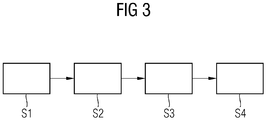
- Fig. 3 shows an embodiment of a method according to the invention.
- a step S1 involves moving-in particular freehand-a test head along a test object surface and a simultaneous measurement carried out within a measuring area consisting of partial areas by emitting ultrasonic pulses into the test object by means of the test head and receiving respective echo signals corresponding to the emitted ultrasonic pulses by means of the test head.
- a step S3 is used to create an image of a predetermined test area of the test object based on a superimposition and averaging of amplitude values of the received echo signals by means of a data processing device taking into account the respectively detected measuring positions of the test head when generating the image of the test area of the test object, wherein the detection of a respective Measuring position of the test head is carried out by means of a detection device in a step S2.
- a fourth step S4 on the basis of an evaluation variable for detecting irregularities with respect to the respectively detected measurement positions within the measurement area, a weighting of each echo signal received for the respectively detected measurement position for the production of the image by means of the data processing device is carried out such that the irregularities are compensated.
- the SAFT method known per se can be applied reliably even in the case of manual guidance of a test head by positioning and orientation detection of the test head 3 during the process as described above carried out the ultrasonic test of the test object 1 and at the Creation of an image 5 of a region of the test object 1 to be checked is taken into account.
Landscapes
- Physics & Mathematics (AREA)
- General Physics & Mathematics (AREA)
- Engineering & Computer Science (AREA)
- General Health & Medical Sciences (AREA)
- Analytical Chemistry (AREA)
- Pathology (AREA)
- Immunology (AREA)
- Health & Medical Sciences (AREA)
- Life Sciences & Earth Sciences (AREA)
- Chemical & Material Sciences (AREA)
- Biochemistry (AREA)
- Acoustics & Sound (AREA)
- Remote Sensing (AREA)
- Radar, Positioning & Navigation (AREA)
- Computer Networks & Wireless Communication (AREA)
- Signal Processing (AREA)
- Probability & Statistics with Applications (AREA)
- Investigating Or Analyzing Materials By The Use Of Ultrasonic Waves (AREA)
- Ultra Sonic Daignosis Equipment (AREA)
Description
- Die Erfindung betrifft ein Verfahren sowie eine Vorrichtung zur Ultraschallprüfung eines Prüfobjekts der in den Oberbegriffen der unabhängigen Patentansprüche angegebenen Art.
- Zur zerstörungsfreien Prüfung von Prüfobjekten sind unterschiedlichste Ultraschallprüfverfahren bekannt. Zur besseren Lokalisierung und Trennung von Defekten bei der zerstörungsfreien Prüfung mit Ultraschall ist die Analysetechnik SAFT (Synthetic Aperture Focusing Technique) bekannt. Die Inspektion erfolgt dabei wie bei einer klassischen Ultraschallprüfung, jedoch werden die Daten ohne eine Gleichrichtung aufgezeichnet. Bei der anschließenden Analyse der Messdaten werden Amplitudensummen aus einer Vielzahl von Messsignalen für jeweilige kleine Volumenelemente, welche auch als sogenannte Voxel bezeichnet werden, ermittelt. Die Ultraschallprüfung kann unter Zuhilfenahme der SAFT-Analyse beispielsweise bei einer manuellen Bewegung eines die Ultraschallimpulse aussendenden und die korrespondierenden Echosignale empfangenden Prüfkopfes eingesetzt werden. Eine derartige SAFT-Prüfung ist beispielsweise in der
DE 10 2013 200974.7 beschrieben. - Durch den Einsatz von sogenannten Phased-Array-Prüfköpfen können Prüfobjekte nicht nur mechanisch sondern auch elektronisch gescannt werden, d. h. dass durch eine Art elektronisches Verschieben der aktiven Zone des Prüfkopfes mehrere Messungen in einem definierten Raster durchgeführt werden. Bei einem stationären Prüfkopf können Daten, die mit demselben elektronischen Scan aufgenommen wurden, mit der SAFT-Analyse ausgewertet werden. Dies funktioniert sowohl bei unbewegtem Prüfkopf als auch bei während des elektronischen Scans bewegten Prüfkopf, wenn die exakte Sende- und Empfangsposition sowie Einschallwinkel und Fokussierung zum Rekonstruktionszeitpunkt bekannt sind.
- Die
DE 10 2009 050 160 A1 offenbart ein Verfahren und eine Vorrichtung zur Ultraschallprüfung eines Prüfobjektes, bei dem Ultraschallwellen über eine Oberfläche des Prüfobjektes in das Prüfobjekt eingekoppelt werden. - Es ist die Aufgabe der vorliegenden Erfindung, eine verbesserte, insbesondere freihandgeführte Ultraschallprüfung eines Prüfobjekts unter Zuhilfenahme der SAFT-Analyse zu ermöglichen. Insbesondere sollen bei einer manuellen freien Führung eines Prüfkopfes erzeugte Artefakte oder Messfehler bei der SAFT-Auswertung wirksam verkleinert oder entfernt werden.
- Die Aufgabe wird durch ein Verfahren gemäß dem Anspruch 1 und eine Vorrichtung gemäß dem Anspruch 10 gelöst. Das erfindungsgemäße Verfahren zur Ultraschallprüfung eines Prüfkobjekts umfasst die folgenden Schritte: Bewegen eines Prüfobjekts entlang einer Prüfobjektoberfläche und Aussenden von Ultraschallimpulsen in das Prüfobjekt mittels des Prüfkopfes; Empfangen jeweiliger mit den ausgesendeten Ultraschallimpulsen korrespondierender Echosignale mittels des Prüfkopfes; Erstellen einer Abbildung eines vorgegebenen Prüfbereichs des Prüfobjekts basierend auf einer Überlagerung und Mittelung von Amplitudenwerten der empfangenen Echosignale mittels einer Datenverarbeitungseinrichtung. Mit anderen Worten umfasst das erfindungsgemäße Verfahren zur Ultraschallprüfung eines Prüfobjekts die bei einer SAFT-Analyse erforderlichen Schritte, wobei zusätzlich die jeweiligen Positionen des Prüfkopfes bei Aussenden der Ultraschallsignale und/oder bei Empfangen der korrespondierenden Echosignale mittels einer Erfassungseinrichtung erfasst und die jeweils erfassten Positionen des Prüfkopfes beim Erzeugen der Abbildung des Prüfbereichs des Prüfobjektes berücksichtigt werden.
- Gemäß einem ersten Aspekt erfolgt ein manuelles Bewegen eines frei geführten Prüfkopfes entlang einer Prüfobjektsoberfläche und innerhalb einer aus Teilbereichen bestehenden Messfläche ausgeführtes Messen mittels Aussenden von Ultraschallimpulsen in das Prüfobjekt mittels des Prüfkopfes und Empfangen jeweiliger mit den ausgesendeten Ultraschallimpulsen korrespondierender Echosignale mittels des Prüfkopfes; Erstellen einer Abbildung eines vorgegebenen Prüfbereichs des Prüfobjekts basierend auf einer Überlagerung und Mittelung von Amplitudenwerten der empfangenen Echosignale mittels einer Datenverarbeitungseinrichtung; Erfassen einer jeweiligen Messposition des Prüfkopfes mittels einer Erfassungseinrichtung; Berücksichtigen der jeweils erfassten Messpositionen des Prüfkopfes beim Erzeugen der Abbildung des Prüfbereichs des Prüfobjekts; Bestimmen einer Bewertungsgröße zur Erfassung von Unregelmäßigkeiten hinsichtlich der jeweils erfassten Messpositionen innerhalb der Messfläche mittels der Datenverarbeitungseinrichtung; anhand der Bewertungsgröße ausgeführtes Gewichten jedes zu der jeweils erfassten Messposition empfangenen Echosignals für das Erstellen der Abbildung (5) mittels der Datenverarbeitungseinrichtung derart, dass die Unregelmäßigkeiten ausgeglichen werden.
- Gemäß einem zweiten Aspekt wird eine Vorrichtung zur Ultraschallprüfung eines Prüfobjekts vorgeschlagen, aufweisend: einen Prüfkopf, der entlang einer Prüfobjektsoberfläche und innerhalb einer aus Teilbereichen bestehenden Messfläche manuell frei bewegbar ist und mittels Aussenden von Ultraschallimpulsen in das Prüfobjekt und Empfangen jeweiliger mit den ausgesendeten Ultraschallimpulsen korrespondierender Echosignale misst; eine Erfassungseinrichtung, die eine jeweilige Messposition des Prüfkopfes erfasst; eine Datenverarbeitungseinrichtung, die eine Abbildung eines vorgegebenen Prüfbereichs des Prüfobjekts basierend auf einer Überlagerung und Mittelung von Amplitudenwerten der empfangenen Echosignale erstellt; und die jeweils erfassten Messpositionen des Prüfkopfes beim Erzeugen der Abbildung des Prüfbereichs des Prüfobjekts berücksichtigt; wobei die Datenverarbeitungseinrichtung mittels mindestens einer Bewertungsgröße zur Erfassung von Unregelmäßigkeiten hinsichtlich der jeweils erfassten Messpositionen innerhalb der Messfläche jedes zu der jeweils erfassten Messposition empfangene Echosignal für das Erstellen der Abbildung derart gewichtet, dass die Unregelmäßigkeiten ausgeglichen werden.
- Erfindungsgemäß ist erkannt worden, dass bei einer manuellen Führung ein Prüfkopf nicht präzise geführt wird und Messungen in einem schwankenden Raster beziehungsweise entlang krummer Bahnen ausgeführt werden, so dass auf diese Weise Artefakte erzeugt werden. Um Artefakte zu reduzieren soll ein Echosignal zu jedem Messpunkt nicht direkt zur SAFT-Auswertung verwendet werden. Echosignale sollen entsprechend einer Dichte und Verteilung von Messpunkten auf einer Messfläche so ausgewählt und/oder gewichtet werden, dass alle Teile der Messfläche zu jedem rekonstruierten Voxel beziehungsweise Prüfbereichs des Prüfobjekts möglichst gleichmäßig beitragen. Voraussetzung ist dabei, dass zuverlässige Positionsinformationen für jede einzelne Messung zur Verfügung stehen.
- Die erfindungsgemäße Lösung bewirkt eine verbesserte SAFT-Auswertung von Prüfungen mit freihändig geführtem Prüfkopf. Ebenso können Artefakte wirksam verringert und ein Signal-zu-Rausch-Abstand SNR des SAFT-Ergebnisses wirksam vergrößert werden. Es können ebenso Unregelmäßigkeiten ausgeglichen werden, deren Ursachen nicht in der Freihandführung des Prüfkopf liegen, sondern beispielsweise durch Ankoppelschwankungen verursacht sind.
- Erfindungsgemäß wird eine lokale Messdichte als Bewertungsgröße bestimmt und ein Gewichten erfolgt derart, dass Echosignale von Messpositionen mit großer lokaler Messdichte weniger stark gewichtet werden, als Echosignale von Messpositionen mit durchschnittlicher oder kleiner Messdichte.
- Gemäß einer vorteilhaften Ausgestaltung kann ein Bestimmen der lokalen Messdichte aus einer jeweiligen Anzahl von erfassten Messpositionen je Einheitsfläche der Messfläche oder je Einheitslänge mindestens einer Abtastlinie der Messfläche erfolgen.
- Gemäß einer weiteren vorteilhaften Ausgestaltung kann ein Gewichten derart erfolgen, dass Echosignale von Messpositionen umgekehrt proportional zur lokalen Messdichte gewichtet werden.
- Gemäß einer weiteren vorteilhaften Ausgestaltung kann die lokale Messdichte mittels Summieren aller Kehrwerte aller Abstände einer erfassten Messposition zu allen anderen erfassten Messpositionen innerhalb eines vorgegebenen ersten Radius bestimmt werden.
- Gemäß einer weiteren vorteilhaften Ausgestaltung kann ein Gewichten derart erfolgen, dass Echosignale von Messpositionen mit relativ größter lokaler Messdichte mit Null gewichtet werden.
- Gemäß einer weiteren vorteilhaften Ausgestaltung kann ein erneutes Bestimmen der lokalen Messdichte innerhalb eines vorgegebenen zweiten Radius um die Messpositionen erfolgen, deren Echosignale mit Null gewichtet wurden.
- Gemäß einer weiteren vorteilhaften Ausgestaltung kann ein wiederholtes Weglassen mit Null gewichteter Messpositionen und erneutes Bestimmen der lokalen Messdichte erfolgen, solange eine vorgegebene Mindestmessdichte nicht unterschritten wird.
- Gemäß einer weiteren vorteilhaften Ausgestaltung kann ein Bestimmen eines homogenen Beitrags aller Teilbereiche der Messfläche als Bewertungsgröße und Gewichten derart erfolgen, dass die Echosignale von Messpositionen möglichst gleichmäßig zur Abbildung beitragen.
- Gemäß einer weiteren vorteilhaften Ausgestaltung kann ein Erfassen der jeweiligen Messposition des Prüfkopfes bei Aussenden des Ultraschallsignals und/oder bei Empfangen des korrespondierenden Echosignals erfolgen.
- Die Erfindung wird anhand von Ausführungsbeispielen in Verbindung mit den Figuren näher beschreiben. Es zeigen:
- Fig. 1
- ein Ausführungsbeispiel einer erfindungsgemäßen Vorrichtung;
- Fig. 2
- eine beispielhafte Prüfkopfbewegung über eine Messfläche im Rahmen der Prüfdurchführung;
- Fig. 3
- ein Ausführungsbeispiel eines erfindungsgemäßen Verfahrens.
-
Fig. 1 zeigt ein erstes Ausführungsbeispiel einer erfindungsgemäßen Vorrichtung, wobei die Position eines Prüfkopfes 3 auf einer Oberfläche 2 eines Prüfobjekts 1 während der Dauer der Prüfung gemessen wird. Die Messung der jeweiligen Position erfolgt dabei innerhalb vergleichsweise kurzer Intervalle und mit einem definierten Zeitbezug relativ zu den zur Inspektion des Prüfobjekts 1 ausgesandten Ultraschallimpulsen. Vorzugsweise erfolgt die Positionsmessung mittels einer Erfassungseinrichtung 9 jeweils dann, wenn ein Ultraschallimpuls ausgesendet wird. Zusätzlich kann auch noch jeweils eine Positionsmessung erfolgen, wenn das zu dem ausgesendeten Ultraschallimpuls korrespondierende Echosignal empfangen wird. - In Abhängigkeit von den erfassten bzw. gemessenen jeweiligen Positionen des Prüfkopfes 3 wird eine jeweils momentane Position des Prüfkopfes 3, vorzugsweise zum Zeitpunkt eines jeweiligen Aussendens des Ultraschallimpulses, ermittelt und bei der SAFT-Analyse zur Bestimmung eines Abstandes zwischen einem zu rekonstruierenden Voxel und der tatsächlichen Messposition verwendet.
- Die erfindungsgemäße Vorrichtung und das Verfahren zur Ultraschallprüfung eines Prüfobjekts sollen unter Zuhilfenahme der SAFT-Analyse bei bewegtem, insbesondere bei freihandgeführtem, Prüfkopf 3 angewendet werden. Vorzugsweise kann der Prüfkopf 3 dabei manuell entlang der Prüfobjektoberfläche 2 bewegt werden. Insbesondere kann der Prüfkopf 3 bei dem erfindungemäßen Verfahren frei auf der Prüfobjektoberfläche 2 geführt werden. Die Lokalisation von Defekten innerhalb des Prüfobjekts 1 wird durch das Verfahren erheblich verbessert, wobei einzelne Defekte besser voneinander unterschieden und das Signalrauschverhältnis insbesondere bei einer manuellen, insbesondere bei einer freihandgeführten Prüfung, verbessert wird. Dadurch ergibt sich bei der Erstellung der Abbildung 5 des Prüfbereichs des Prüfobjekts 1 eine verbesserte Auflösung von Gruppenanzeigen, also von nahe beieinander liegenden Einzelanzeigen, die ohne eine SAFT-Analyse nicht voneinander getrennt werden könnten und daher als eine größere Anzeige bewertet werden würden, und insbesondere eine verbesserte Detektion von kleinen Defekten. Unter kleinen Defekten sind dabei Defekte mit einer Abmessung zu verstehen, welche im Verhältnis zur verwendeten Wellenlänge der Ultraschallimpulse klein sind. Zudem können die Prüfergebnisse 5, welche mit dem erfindungsgemäßen Verfahren erzielt werden, durch eine Referenzierung zu einem dreidimensionalen digitalen Modell des Prüfobjekts besonders intuitiv interpretiert werden.
- Es kann aus den gemessenen Positionen und Orientierungen und dem jeweiligen Zeitbezug die momentane Position und Orientierung des Prüfkopfes 3 zum Zeitpunkt jedes Ultraschallimpulses berechnet und bei der sogenannten SAFT-Analyse zur Bestimmung des Abstandes zwischen rekonstruiertem jeweiligen Voxel und Messposition benutzt werden. Dabei kann anhand der erfassten Position und Orientierung des Prüfkopfes 3 die Mittenposition der aktiven Apertur des Prüfkopfes beim Aussenden der Ultraschallsignale ermittelt und beim Erzeugen der Abbildung des Prüfbereichs des Prüfobjekts 1 berücksichtigt werden. Unter der aktiven Apertur ist dabei der Teil des Prüfkopfes 3 zu verstehen, welcher als wirksame Sende- bzw. Empfangsfläche dient. Ein räumlicher Versatz zwischen der jeweiligen Positionsmessung und der Position des Prüfkopfes 3 kann mit Hilfe der erfassten Information über die Prüfkopforientierung herausgerechnet werden.
- In vorteilhafter Ausgestaltung der Vorrichtung kann es vorgesehen sein, dass die Erfassungseinrichtung 9 einen optischen Bewegungssensor umfasst, welcher an dem Prüfkopf 3 angebracht ist, und mittels welchem die jeweils relative Position zu einem Referenzpunkt erfassbar ist. Bei dem Referenzpunkt kann es sich beispielsweise um die Position handeln, an welcher der Prüfkopf 3 zu Beginn der Ultraschallprüfung angeordnet worden ist. Vorzugsweise umfasst die Erfassungseinrichtung 9 dabei einen weiteren nicht dargestellten optischen Bewegungssensor, welcher mit einem vorgegebenen Abstand entfernt von dem anderen optischen Bewegungssensor an dem Prüfkopf 3 angebracht ist und mittels welchem die jeweils relative Position zu dem Referenzpunkt erfassbar ist.
- In weiterer vorteilhafter Ausgestaltung der Vorrichtung kann es vorgesehen sein, dass die Erfassungseinrichtung 9 eine Bilderfassungseinrichtung umfasst, mittels welcher eine Mehrzahl von am Prüfkopf 3 angebrachten optischen Markierungen erfassbar und basierend darauf die Position und Orientierung des Prüfkopfes 3 ermittelbar sind.
- Eine Vorrichtung zur Ultraschallprüfung eines Prüfobjekts 1 ist in einer schematischen Perspektivansicht gezeigt. Die Vorrichutng umfasst einen entlang einer Prüfobjektoberfläche 2 freihändisch bewegbaren Prüfkopf 3 mittels welchem Ultraschallimpulse in das Prüfobjekt 1 aussendbar und jeweilige mit den ausgesendeten Ultraschallimpulsen korrespondierende Echosignale empfangbar sind. Die Vorrichtung umfasst des Weiteren eine Datenverarbeitungseinrichtung 7, mittels welcher eine Abbildung 5 eines Prüfbereichs des Prüfobjekts 1 basierend auf einer Überlagerung und Mittlung von Amplitudenwerten der empfangenen Echosignale erstellbar ist. Mit anderen Worten ist die Vorrichtung zur Ultraschallprüfung des Prüfobjekts 1 dazu ausgelegt, eine sogenannte SAFT-Analyse (Syntetic Aperture Focusing Technique) im Rahmen der Ultraschallprüfung des Prüfobjekts 1 durchzuführen.
-
Fig. 1 zeigt die Datenverarbeitungseinrichtung 7, die eine Abbildung 5) eines vorgegebenen Prüfbereichs des Prüfobjekts 1 basierend auf einer Überlagerung und Mittelung von Amplitudenwerten der empfangenen Echosignale erstellt; und die jeweils erfassten Messpositionen des Prüfkopfes 3 beim Erzeugen der Abbildung 5 des Prüfbereichs des Prüfobjekts 1 berücksichtigt. Die Datenverarbeitungseinrichtung 7 gewichtet mittels mindestens einer Bewertungsgröße zur Erfassung von Unregelmäßigkeiten hinsichtlich der jeweils erfassten Messpositionen innerhalb der Messfläche jedes zu der jeweils erfassten Messposition empfangene Echosignal für das Erstellen der Abbildung 5 derart, dass die Unregelmäßigkeiten ausgeglichen werden. Der Prüfkopf 3 misst das Prüfobjekt 1 innerhalb einer definierten Messfläche 11. Die Messfläche 11 kann beispielsweise eine ebene Rechteckefläche sein. -
Fig. 2 zeigt ein Ausführungsbeispiel einer Messfläche 11 auf der Messpositionen M dargestellt sind. Messpunkte oder Messlinienabschnitte sind hier entlang einer mäanderförmigen Abtastlinie oder Scanlinie dargestellt. Entlang dieser Linie ist eine freihandgeführte Bewegung des Prüfkopfes ersichtlich. Es ergeben sich an den umrahmten Teilbereichen bzw. Flächen Überdeckungen der Messung und von Messpositionen M. Auf diese Weise sind Verteilungen von Messpositionen M einfach ersichtlich und Dichtewerte können abgeschätzt werden. Entsprechend ist eine lokale Messdichte, die ebenso als lokale Schussdichte bezeichnet werden kann, dargestellt. Um durch zu hohe Schussdichten verursachte Unregelmäßigkeiten zu kompensieren wird nun vorgeschlagen, Echosignale von Messpositionen M mit großer lokaler Messdichte weniger zu berücksichtigen als Echosignale von Messpositionen M mit durchschnittlicher oder kleiner Messdichte. Dies kann dazu führen, dass beispielsweise Echosignale aus dem Bereich oder Teilbereich G0 mit der Zahl Null gewichtet und damit vollständig zur Erzeugung einer Abbildung entfernt werden. Da die relative lokale Messdichte im Teilbereich Gk zwar groß, aber kleiner als im Teilbereich G0 ist, ist es vorteilhaft beispielsweise dortige Echosignale für die Abbildung abzuschwächen und kleiner als 100% zu gewichten. Die genaue Auswahl der Gewichtungsfaktoren kann experimentell oder mathematisch bestimmt erfolgen. -
Fig. 3 zeigt ein Ausführungsbeispiel eines erfindungsgemäßen Verfahrens. Zur Ultraschallprüfung eines Prüfobjekts können beispielsweise folgende Schritte ausgeführt werden. Mit einem Schritt S1 erfolgt ein Bewegen - insbesondere freihändig - eines Prüfkopfes entlang einer Prüfobjektsoberfläche und ein innerhalb einer aus Teilbereichen bestehenden Messfläche ausgeführtes gleichzeitiges Messen mittels Aussenden von Ultraschallimpulsen in das Prüfobjekt mittels des Prüfkopfes und Empfangen jeweiliger mit den ausgesendeten Ultraschallimpulsen korrespondierender Echosignale mittels des Prüfkopfes. Mit einem Schritt S3 erfolgt ein Erstellen einer Abbildung eines vorgegebenen Prüfbereichs des Prüfobjekts basierend auf einer Überlagerung und Mittelung von Amplitudenwerten der empfangenen Echosignale mittels einer Datenverarbeitungseinrichtung unter Berücksichtigung der jeweils erfassten Messpositionen des Prüfkopfes beim Erzeugen der Abbildung des Prüfbereichs des Prüfobjekts, wobei das Erfassen einer jeweiligen Messposition des Prüfkopfes mittels einer Erfassungseinrichtung in einem Schritt S2 ausgeführt wird. Mit einem vierten Schritt S4 anhand einer Bewertungsgröße zur Erfassung von Unregelmäßigkeiten hinsichtlich der jeweils erfassten Messpositionen innerhalb der Messfläche ein Gewichten jedes zu der jeweils erfassten Messposition empfangenen Echosignals für das Erstellen der Abbildung mittels der Datenverarbeitungseinrichtung derart ausgeführt, dass die Unregelmäßigkeiten ausgeglichen werden. - Mittels der Vorrichtung und den beschriebenen Verfahren zur Ultraschallüberprüfung eines Prüfobjekts 1 kann das an und für sich bekannte SAFT-Verfahren auch bei einer manuellen Führung eines Prüfkopfes auf zuverlässige Weise angewendet werden, indem wie in der erläuterten Weise eine Positions- und Orientierungserfassung des Prüfkopfes 3 während der Ultraschallprüfung des Prüfobjekts 1 durchgeführt und bei der Erstellung einer Abbildung 5 eines zu überprüfenden Bereichs des Prüfobjekts 1 berücksichtigt wird.
Claims (18)
- Verfahren zur Ultraschallprüfung eines Prüfobjekts (1), mit den Schritten:- Bewegen - insbesondere freihändig - eines Prüfkopfes (3) entlang einer Prüfobjektsoberfläche (2) und innerhalb einer aus Teilbereichen bestehenden Messfläche (11) ausgeführtes Messen mittels Aussenden von Ultraschallimpulsen in das Prüfobjekt (1) mittels des Prüfkopfes (3) und Empfangen jeweiliger mit den ausgesendeten Ultraschallimpulsen korrespondierender Echosignale mittels des Prüfkopfes (3);- Erstellen einer Abbildung (5) eines vorgegebenen Prüfbereichs des Prüfobjekts (1) basierend auf einer Überlagerung und Mittelung von Amplitudenwerten der empfangenen Echosignale mittels einer Datenverarbeitungseinrichtung (7);- Erfassen einer jeweiligen Messposition (M) des Prüfkopfes (3) mittels einer Erfassungseinrichtung (9);- Berücksichtigen der jeweils erfassten Messpositionen des Prüfkopfes (3) beim Erzeugen der Abbildung (5) des Prüfbereichs des Prüfobjekts (1);- Bestimmen einer Bewertungsgröße zur Erfassung von Unregelmäßigkeiten hinsichtlich der jeweils erfassten Messpositionen innerhalb der Messfläche mittels der Datenverarbeitungseinrichtung (7);- anhand der Bewertungsgröße ausgeführtes Gewichten jedes zu der jeweils erfassten Messposition empfangenen Echosignals für das Erstellen der Abbildung (5) mittels der Datenverarbeitungseinrichtung (7) derart, dass die Unregelmäßigkeiten ausgeglichen werden,gekennzeichnet durch
Bestimmen einer lokalen Messdichte als Bewertungsgröße und Gewichten derart, dass Echosignale von Messpositionen (M) mit großer lokaler Messdichte weniger stark gewichtet werden, als Echosignale von Messpositionen mit durchschnittlicher oder kleiner Messdichte. - Verfahren nach Anspruch 1,
gekennzeichnet durch
Bestimmen der lokalen Messdichte aus einer jeweiligen Anzahl von erfassten Messpositionen je Einheitsfläche der Messfläche oder je Einheitslänge mindestens einer Abtastlinie der Messfläche. - Verfahren nach Anspruch 1,
gekennzeichnet durch
Bestimmen der lokalen Messdichte mittels Summieren aller Kehrwerte aller Abstände einer erfassten Messposition zu allen anderen erfassten Messpositionen innerhalb eines vorgegebenen ersten Radius. - Verfahren nach Anspruch 1, 2 oder 3,
gekennzeichnet durch
Gewichten derart, dass Echosignale von Messpositionen umgekehrt proportional zur lokalen Messdichte gewichte werden. - Verfahren nach Anspruch 1, 2, 3 oder 4,
gekennzeichnet durch
Gewichten derart, dass Echosignale von Messpositionen mit relativ größter lokaler Messdichte mit Null gewichtet werden. - Verfahren nach Anspruch 5,
gekennzeichnet durch
erneutes Bestimmen der lokalen Messdichte innerhalb eines vorgegebenen zweiten Radius um die Messpositionen, deren Echosignale mit Null gewichtet wurden. - Verfahren nach Anspruch 5 und 6,
gekennzeichnet durch
wiederholtes Weglassen mit Null gewichteter Messpositionen und erneutes Bestimmen der lokalen Messdichte solange eine vorgegebene Mindestmessdichte nicht unterschritten wird. - Verfahren nach einem der vorhergehenden Ansprüche,
gekennzeichnet durch
Bestimmen eines homogenen Beitrags aller Teilbereiche der Messfläche als Bewertungsgröße und Gewichten derart, dass die Echosignale von Messpositionen möglichst gleichmäßig zur Abbildung (5) beitragen. - Verfahren nach einem der vorhergehenden Ansprüche,
gekennzeichnet durch
Erfassen der jeweiligen Messposition des Prüfkopfes (16) bei Aussenden des Ultraschallsignals und/oder bei Empfangen des korrespondierenden Echosignals. - Vorrichtung zur Ultraschallprüfung eines Prüfobjekts (1), aufweisend:einen Prüfkopf (3), der entlang einer Prüfobjektsoberfläche (2) und innerhalb einer aus Teilbereichen bestehenden Messfläche, insbesondere freihändig, bewegbar ist und mittels Aussenden von Ultraschallimpulsen in das Prüfobjekt (1) und Empfangen jeweiliger mit den ausgesendeten Ultraschallimpulsen korrespondierender Echosignale misst;eine Erfassungseinrichtung, die eine jeweilige Messposition des Prüfkopfes (3) erfasst;eine Datenverarbeitungseinrichtung (7), die eine Abbildung (5) eines vorgegebenen Prüfbereichs des Prüfobjekts (1) basierend auf einer Überlagerung und Mittelung von Amplitudenwerten der empfangenen Echosignale erstellt;und die jeweils erfassten Messpositionen des Prüfkopfes (3) beim Erzeugen der Abbildung (5) des Prüfbereichs des Prüfobjekts (1) berücksichtigt;wobei die Datenverarbeitungseinrichtung (7) mittels mindestens einer Bewertungsgröße zur Erfassung von Unregelmäßigkeiten hinsichtlich der jeweils erfassten Messpositionen innerhalb der Messfläche jedes zu der jeweils erfassten Messposition empfangene Echosignal für das Erstellen der Abbildung (5) derart gewichtet, dass die Unregelmäßigkeiten ausgeglichen werdendadurch gekennzeichnet, dassdie Datenverarbeitungseinrichtung (7) eine lokale Messdichte als Bewertungsgröße bestimmt und ein Gewichten derart ausführt, dass Echosignale von Messpositionen (M) mit großer lokaler Messdichte weniger stark gewichtet werden, als Echosignale von Messpositionen mit durchschnittlicher oder kleiner Messdichte.
- Vorrichtung nach Anspruch 10,
dadurch gekennzeichnet, dass
die Datenverarbeitungseinrichtung (7) die lokale Messdichte aus einer jeweiligen Anzahl von erfassten Messpositionen je Einheitsfläche der Messfläche oder je Einheitslänge mindestens einer Abtastlinie der Messfläche bestimmt. - Vorrichtung nach einem der Ansprüche 10 oder 11,
dadurch gekennzeichnet, dass
die Datenverarbeitungseinrichtung (7) die lokale Messdichte mittels Summieren aller Kehrwerte aller Abstände einer erfassten Messposition zu allen anderen erfassten Messpositionen innerhalb eines vorgegebenen ersten Radius bestimmt. - Vorrichtung nach Anspruch 10, 11 oder 12,
dadurch gekennzeichnet, dass
die Datenverarbeitungseinrichtung (7) derart gewichtet, dass Echosignale von Messpositionen umgekehrt proportional zur lokalen Messdichte gewichtet werden. - Vorrichtung nach Anspruch 10, 11, 12 oder 13,
dadurch gekennzeichnet, dass
die Datenverarbeitungseinrichtung (7) derart gewichtet, dass Echosignale von Messpositionen mit relativ größter lokaler Messdichte mit Null gewichtet werden. - Vorrichtung nach Anspruch 14,
dadurch gekennzeichnet, dass
die Datenverarbeitungseinrichtung (7) die lokale Messdichte innerhalb eines vorgegebenen zweiten Radius um die Messpositionen, deren Echosignale mit Null gewichtet wurden, erneut bestimmt. - Vorrichtung nach Anspruch 14 und 15,
dadurch gekennzeichnet, dass
die Datenverarbeitungseinrichtung (7) mit Null gewichtete Messpositionen entfernt und die lokale Messdichte, solange eine vorgegebene Mindestmessdichte nicht unterschritten wird, erneut bestimmt. - Vorrichtung nach einem der vorhergehenden Ansprüche 9 bis 16,
dadurch gekennzeichnet, dass
die Datenverarbeitungseinrichtung (7) eine homogenen Beitrag aller Teilbereiche der Messfläche als Bewertungsgröße bestimmt und derart gewichtet, dass die Echosignale von Messpositionen möglichst gleichmäßig zur Abbildung (5) beitragen. - Vorrichtung nach einem der vorhergehenden Ansprüche 10 bis 17,
dadurch gekennzeichnet, dass
die Erfassungseinrichtung die jeweiligen Messposition des Prüfkopfes (16) bei Aussenden des Ultraschallsignals und/oder bei Empfangen des korrespondierenden Echosignals erfasst.
Applications Claiming Priority (2)
| Application Number | Priority Date | Filing Date | Title |
|---|---|---|---|
| DE102013201975.0A DE102013201975A1 (de) | 2013-02-07 | 2013-02-07 | Verfahren und Vorrichtung zur Verbesserung der SAFT-Analyse bei unregelmäßiger Messung |
| PCT/EP2013/072181 WO2014121858A1 (de) | 2013-02-07 | 2013-10-23 | Verfahren und vorrichtung zur verbesserung der saft-analyse bei unregelmässiger messung |
Publications (2)
| Publication Number | Publication Date |
|---|---|
| EP2898322A1 EP2898322A1 (de) | 2015-07-29 |
| EP2898322B1 true EP2898322B1 (de) | 2018-12-26 |
Family
ID=49518935
Family Applications (1)
| Application Number | Title | Priority Date | Filing Date |
|---|---|---|---|
| EP13786194.4A Active EP2898322B1 (de) | 2013-02-07 | 2013-10-23 | Verfahren und vorrichtung zur verbesserung der saft-analyse bei unregelmässiger lokaler messdichte |
Country Status (10)
| Country | Link |
|---|---|
| US (1) | US10222352B2 (de) |
| EP (1) | EP2898322B1 (de) |
| JP (1) | JP6022088B2 (de) |
| KR (1) | KR101774514B1 (de) |
| CN (1) | CN104956218B (de) |
| BR (1) | BR112015016646B1 (de) |
| CA (1) | CA2900298C (de) |
| DE (1) | DE102013201975A1 (de) |
| IN (1) | IN2015DN03891A (de) |
| WO (1) | WO2014121858A1 (de) |
Cited By (2)
| Publication number | Priority date | Publication date | Assignee | Title |
|---|---|---|---|---|
| WO2023117079A1 (de) | 2021-12-22 | 2023-06-29 | Siemens Aktiengesellschaft | System und verfahren zur ermittlung einer grösse eines defekts in einem bauteil |
| WO2023134867A1 (de) | 2022-01-14 | 2023-07-20 | Siemens Aktiengesellschaft | Verfahren und system zur bestimmung der position eines prüfkopfes während einer saft-untersuchung |
Families Citing this family (4)
| Publication number | Priority date | Publication date | Assignee | Title |
|---|---|---|---|---|
| GB201304498D0 (en) | 2013-03-13 | 2013-04-24 | Univ Newcastle | Ultrasound imaging apparatus |
| US20140283611A1 (en) * | 2013-03-25 | 2014-09-25 | Jason HABERMEHL | System and a method of adaptive focusing in a phased array ultrasonic system |
| FR3051913B1 (fr) * | 2016-05-25 | 2020-12-11 | Electricite De France | Procede de detection par ultrasons de defauts dans un materiau |
| CN112881537B (zh) * | 2021-01-22 | 2023-06-20 | 西安增材制造国家研究院有限公司 | 一种椭圆合成孔径聚焦的激光超声信号成像方法 |
Family Cites Families (35)
| Publication number | Priority date | Publication date | Assignee | Title |
|---|---|---|---|---|
| DK138861B (da) * | 1972-08-28 | 1978-11-06 | Akad Tekn Videnskaber | Apparat til ultralydundersøgelse. |
| JPS51128183A (en) * | 1975-04-30 | 1976-11-08 | Tokyo Shibaura Electric Co | Ultrasonic diagnostic device |
| DE3277083D1 (en) * | 1982-10-19 | 1987-10-01 | Hitachi Ltd | Ultrasonic testing apparatus |
| JPS5975147A (ja) * | 1982-10-22 | 1984-04-27 | Hitachi Ltd | 超音波検査装置 |
| JPS61134663A (ja) * | 1984-12-06 | 1986-06-21 | Toshiba Corp | 超音波探傷装置 |
| US5278757A (en) | 1991-11-15 | 1994-01-11 | The Trustees Of The University Of Pennsylvania | Synthetic aperture ultrasonic imaging system using a minimum or reduced redundancy phased array |
| US5699803A (en) * | 1996-08-09 | 1997-12-23 | Emerson Electric Co. | Method of performing ultrasonic examination |
| US5952577A (en) * | 1997-07-21 | 1999-09-14 | Sonotron Ltd. | Ultrasonic imaging system |
| US9402601B1 (en) * | 1999-06-22 | 2016-08-02 | Teratech Corporation | Methods for controlling an ultrasound imaging procedure and providing ultrasound images to an external non-ultrasound application via a network |
| US20040015079A1 (en) * | 1999-06-22 | 2004-01-22 | Teratech Corporation | Ultrasound probe with integrated electronics |
| US20040225220A1 (en) * | 2003-05-06 | 2004-11-11 | Rich Collin A. | Ultrasound system including a handheld probe |
| ITFI20030254A1 (it) | 2003-10-08 | 2005-04-09 | Actis Active Sensors S R L | Metodo e dispositivo perfezionati per l'analisi spettrale |
| DE102004059856B4 (de) * | 2004-12-11 | 2006-09-14 | Fraunhofer-Gesellschaft zur Förderung der angewandten Forschung e.V. | Verfahren zur zerstörungsfreien Untersuchung eines Prüfkörpers mittels Ultraschall |
| EP2157426B1 (de) | 2005-07-07 | 2012-09-19 | Kabushiki Kaisha Toshiba | Laserbasiertes Gerät zur Detektion mittels Ultraschall |
| US7324910B2 (en) * | 2005-12-22 | 2008-01-29 | General Electric Company | Sensor array for navigation on surfaces |
| US7823454B2 (en) * | 2006-11-29 | 2010-11-02 | Babcock & Wilcox Technical Services Group, Inc. | Ultrasonic inspection method |
| JP4491800B2 (ja) * | 2008-03-27 | 2010-06-30 | 住友金属工業株式会社 | 超音波探傷方法及び装置 |
| DE102008002450B4 (de) * | 2008-04-11 | 2022-06-23 | Waygate Technologies Usa, Lp | Verfahren für die zerstörungsfreie Prüfung eines Prüflings mittels Ultraschall sowie Vorrichtung hierzu |
| US8590383B2 (en) * | 2008-06-24 | 2013-11-26 | Alstom Technology Ltd | Ultrasonic inspection probe carrier system for performing non-destructive testing |
| DE102009050160A1 (de) * | 2009-10-21 | 2011-05-05 | Fraunhofer-Gesellschaft zur Förderung der angewandten Forschung e.V. | Verfahren und Vorrichtung zur Ultraschallprüfung eines Prüfobjektes |
| WO2011095896A1 (en) * | 2010-02-08 | 2011-08-11 | Dalhousie University | Ultrasound imaging system using beamforming techniques for phase coherence grating lobe suppression |
| JP5093699B2 (ja) * | 2010-09-09 | 2012-12-12 | 住友金属工業株式会社 | 管端部の超音波探傷装置 |
| CN102043016B (zh) | 2010-11-05 | 2012-08-22 | 上海交通大学 | 基于兰姆波的自主式损伤识别成像方法 |
| DE102011003209A1 (de) | 2011-01-26 | 2012-07-26 | Siemens Aktiengesellschaft | Verfahren und Vorrichtung zur Inspektion eines Objekts zur Erfassung von Oberflächenschäden |
| TW201232476A (en) | 2011-01-27 | 2012-08-01 | Univ Nat Taiwan | Detection system and signal processing method thereof |
| US9037419B2 (en) * | 2011-05-10 | 2015-05-19 | Edison Welding Institute, Inc. | Portable matrix phased array spot weld inspection system |
| DE102011053942A1 (de) * | 2011-09-26 | 2013-03-28 | Ge Sensing & Inspection Technologies Gmbh | Verfahren zur zerstörungsfreien Prüfung eines Prüflings hoher Materialstärke mittels Ultraschall, die Verwendung eines Prüfkopfs zur Ausführung des Verfahrens, ein Ultraschallprüfkopf, eine Ansteuereinheit für einen Ultraschallprüfkopf und eine Vorrichtung für die zerstörungsfreie Prüfung eines Prüflings hoher Materialstärke mittels Ultraschall |
| DE102013200974A1 (de) * | 2013-01-22 | 2014-07-24 | Siemens Aktiengesellschaft | Verfahren und System zur handgeführten Ultraschallprüfung eines Prüfobjekts |
| US9207639B2 (en) * | 2013-01-24 | 2015-12-08 | General Electric Company | Transforming A-scan data samples into a three-dimensional space for facilitating visualization of flaws |
| JP2014176544A (ja) * | 2013-03-15 | 2014-09-25 | Seiko Epson Corp | 超音波測定装置及び超音波画像装置 |
| GB2501625B (en) * | 2013-06-19 | 2014-04-16 | Impact Lab Ltd | Ultrasonic NDT inspection system |
| US9404904B2 (en) * | 2013-11-05 | 2016-08-02 | The Boeing Company | Methods and systems for non-destructive inspection |
| JP6300225B2 (ja) * | 2013-12-03 | 2018-03-28 | 東芝エネルギーシステムズ株式会社 | タービン翼の検査装置及びその検査方法 |
| US20150292915A1 (en) * | 2014-04-11 | 2015-10-15 | Ge-Hitachi Nuclear Energy Americas Llc | Infrared encoding of non-destructive examinations |
| US10234269B2 (en) * | 2015-06-11 | 2019-03-19 | Ge-Hitachi Nuclear Energy Americas Llc | Fiber optic shape sensing technology for encoding of NDE exams |
-
2013
- 2013-02-07 DE DE102013201975.0A patent/DE102013201975A1/de not_active Withdrawn
- 2013-10-23 CN CN201380072507.1A patent/CN104956218B/zh active Active
- 2013-10-23 CA CA2900298A patent/CA2900298C/en active Active
- 2013-10-23 US US14/761,833 patent/US10222352B2/en active Active
- 2013-10-23 KR KR1020157023093A patent/KR101774514B1/ko active IP Right Grant
- 2013-10-23 BR BR112015016646-6A patent/BR112015016646B1/pt not_active IP Right Cessation
- 2013-10-23 JP JP2015556407A patent/JP6022088B2/ja active Active
- 2013-10-23 EP EP13786194.4A patent/EP2898322B1/de active Active
- 2013-10-23 WO PCT/EP2013/072181 patent/WO2014121858A1/de active Application Filing
-
2015
- 2015-05-07 IN IN3891DEN2015 patent/IN2015DN03891A/en unknown
Non-Patent Citations (1)
| Title |
|---|
| None * |
Cited By (2)
| Publication number | Priority date | Publication date | Assignee | Title |
|---|---|---|---|---|
| WO2023117079A1 (de) | 2021-12-22 | 2023-06-29 | Siemens Aktiengesellschaft | System und verfahren zur ermittlung einer grösse eines defekts in einem bauteil |
| WO2023134867A1 (de) | 2022-01-14 | 2023-07-20 | Siemens Aktiengesellschaft | Verfahren und system zur bestimmung der position eines prüfkopfes während einer saft-untersuchung |
Also Published As
| Publication number | Publication date |
|---|---|
| US10222352B2 (en) | 2019-03-05 |
| KR101774514B1 (ko) | 2017-09-04 |
| CA2900298C (en) | 2019-03-05 |
| JP2016507060A (ja) | 2016-03-07 |
| JP6022088B2 (ja) | 2016-11-09 |
| BR112015016646B1 (pt) | 2021-06-08 |
| EP2898322A1 (de) | 2015-07-29 |
| IN2015DN03891A (de) | 2015-10-02 |
| WO2014121858A1 (de) | 2014-08-14 |
| CA2900298A1 (en) | 2014-08-14 |
| BR112015016646A2 (pt) | 2017-07-11 |
| KR20150108927A (ko) | 2015-09-30 |
| CN104956218B (zh) | 2018-02-09 |
| DE102013201975A1 (de) | 2014-08-07 |
| US20150346157A1 (en) | 2015-12-03 |
| CN104956218A (zh) | 2015-09-30 |
Similar Documents
| Publication | Publication Date | Title |
|---|---|---|
| EP2898322B1 (de) | Verfahren und vorrichtung zur verbesserung der saft-analyse bei unregelmässiger lokaler messdichte | |
| EP2932256B1 (de) | Verfahren und system zur handgeführten ultraschallprüfung eines prüfobjekts | |
| DE112006000360B4 (de) | Automatische Ultraschallprüfvorrichtung, automatisches Ultraschallprüfverfahren und Herstellverfahren unter Anwendung des Prüfverfahrens | |
| DE102007020314A1 (de) | Verfahren und Vorrichtung zur Messung eines Flusses durch eine Herzklappe | |
| DE102009015922A1 (de) | Verfahren zum optischen Abtasten und Vermessen einer Szene | |
| DE10128206B4 (de) | Dreidimensionale Ultraschall-Bilderzeugung unter Verwenden einer bewegbaren Sonde | |
| DE60215406T2 (de) | Verfahren und Vorrichtung zur Ultraschallabbildung | |
| WO2007048479A1 (de) | Verfahren und vorrichtung zur bildgebenden ultraschallprüfung an eine dreidimensionalen werkstück | |
| EP2120045A1 (de) | Vorrichtung und Verfahren zur Erzeugung eines Ultraschallbildes mittels eines Gruppenstrahlers | |
| DE102015108480A1 (de) | System und Verfahren für einen dynamischen Gating-Prozess bei der zerstörungsfreien Schweißnahtprüfung | |
| WO2005012941A1 (de) | Verfahren und schaltungsanordnung zur zerstörungsfreien prüfung von gegenständen mittels ultraschallwellen | |
| EP2992321B1 (de) | Verfahren und vorrichtung zur defektgrössenbewertung mittels saft (synthetic aperture focussing technique) | |
| EP2764356B1 (de) | Verfahren und vorrichtung zur detektion von defekten innerhalb eines prüfobjektes | |
| EP3748397A1 (de) | Verfahren und anordnung zur ortsaufgelösten erfassung von schallemissionen, insbesondere ultraschallemissionen | |
| EP1576364B1 (de) | Verfahren zur auswertung von ultraschallsignalen eines fehlers in einem werkstück | |
| DE102019116142A1 (de) | Vorrichtung zur tomografischen Ultraschallprüfung einer Innenstruktur einer Metallbramme und Verfahren zur in-situ Qualitätsprüfung von Metallbrammen | |
| DE10392553T5 (de) | Radjustierung durch drehenden optischen Sensor | |
| EP2607895A1 (de) | Phased-Array Scans mit wählbarer Auflösung | |
| WO2023134867A1 (de) | Verfahren und system zur bestimmung der position eines prüfkopfes während einer saft-untersuchung | |
| DE102012109257B4 (de) | Verfahren und Vorrichtung zur Erzeugung eines Ultraschallbildes | |
| DE102009050160A1 (de) | Verfahren und Vorrichtung zur Ultraschallprüfung eines Prüfobjektes | |
| DE102016221333A1 (de) | Verfahren zur Auswertung einer Ultraschallprüfung sowie Verfahren und Vorrichtung zur Ultraschallprüfung | |
| WO2023117079A1 (de) | System und verfahren zur ermittlung einer grösse eines defekts in einem bauteil | |
| DE102013201469B4 (de) | Verfahren und Vorrichtung zur Oberflächenbestimmung | |
| DE19603574C2 (de) | Verfahren und Gerät zur Abbildung von Ultraschall-Wellenfedern |
Legal Events
| Date | Code | Title | Description |
|---|---|---|---|
| PUAI | Public reference made under article 153(3) epc to a published international application that has entered the european phase |
Free format text: ORIGINAL CODE: 0009012 |
|
| 17P | Request for examination filed |
Effective date: 20150423 |
|
| AK | Designated contracting states |
Kind code of ref document: A1 Designated state(s): AL AT BE BG CH CY CZ DE DK EE ES FI FR GB GR HR HU IE IS IT LI LT LU LV MC MK MT NL NO PL PT RO RS SE SI SK SM TR |
|
| AX | Request for extension of the european patent |
Extension state: BA ME |
|
| DAX | Request for extension of the european patent (deleted) | ||
| RAP1 | Party data changed (applicant data changed or rights of an application transferred) |
Owner name: SIEMENS AKTIENGESELLSCHAFT |
|
| REG | Reference to a national code |
Ref country code: DE Ref legal event code: R079 Ref document number: 502013011930 Country of ref document: DE Free format text: PREVIOUS MAIN CLASS: G01N0029060000 Ipc: G01N0029220000 |
|
| RIC1 | Information provided on ipc code assigned before grant |
Ipc: G01N 29/22 20060101AFI20180712BHEP |
|
| GRAP | Despatch of communication of intention to grant a patent |
Free format text: ORIGINAL CODE: EPIDOSNIGR1 |
|
| STAA | Information on the status of an ep patent application or granted ep patent |
Free format text: STATUS: GRANT OF PATENT IS INTENDED |
|
| INTG | Intention to grant announced |
Effective date: 20180822 |
|
| GRAS | Grant fee paid |
Free format text: ORIGINAL CODE: EPIDOSNIGR3 |
|
| GRAA | (expected) grant |
Free format text: ORIGINAL CODE: 0009210 |
|
| STAA | Information on the status of an ep patent application or granted ep patent |
Free format text: STATUS: THE PATENT HAS BEEN GRANTED |
|
| AK | Designated contracting states |
Kind code of ref document: B1 Designated state(s): AL AT BE BG CH CY CZ DE DK EE ES FI FR GB GR HR HU IE IS IT LI LT LU LV MC MK MT NL NO PL PT RO RS SE SI SK SM TR |
|
| REG | Reference to a national code |
Ref country code: GB Ref legal event code: FG4D Free format text: NOT ENGLISH |
|
| REG | Reference to a national code |
Ref country code: CH Ref legal event code: EP |
|
| REG | Reference to a national code |
Ref country code: AT Ref legal event code: REF Ref document number: 1082113 Country of ref document: AT Kind code of ref document: T Effective date: 20190115 |
|
| REG | Reference to a national code |
Ref country code: DE Ref legal event code: R096 Ref document number: 502013011930 Country of ref document: DE |
|
| REG | Reference to a national code |
Ref country code: IE Ref legal event code: FG4D Free format text: LANGUAGE OF EP DOCUMENT: GERMAN |
|
| PG25 | Lapsed in a contracting state [announced via postgrant information from national office to epo] |
Ref country code: HR Free format text: LAPSE BECAUSE OF FAILURE TO SUBMIT A TRANSLATION OF THE DESCRIPTION OR TO PAY THE FEE WITHIN THE PRESCRIBED TIME-LIMIT Effective date: 20181226 Ref country code: NO Free format text: LAPSE BECAUSE OF FAILURE TO SUBMIT A TRANSLATION OF THE DESCRIPTION OR TO PAY THE FEE WITHIN THE PRESCRIBED TIME-LIMIT Effective date: 20190326 Ref country code: LV Free format text: LAPSE BECAUSE OF FAILURE TO SUBMIT A TRANSLATION OF THE DESCRIPTION OR TO PAY THE FEE WITHIN THE PRESCRIBED TIME-LIMIT Effective date: 20181226 Ref country code: FI Free format text: LAPSE BECAUSE OF FAILURE TO SUBMIT A TRANSLATION OF THE DESCRIPTION OR TO PAY THE FEE WITHIN THE PRESCRIBED TIME-LIMIT Effective date: 20181226 Ref country code: BG Free format text: LAPSE BECAUSE OF FAILURE TO SUBMIT A TRANSLATION OF THE DESCRIPTION OR TO PAY THE FEE WITHIN THE PRESCRIBED TIME-LIMIT Effective date: 20190326 Ref country code: LT Free format text: LAPSE BECAUSE OF FAILURE TO SUBMIT A TRANSLATION OF THE DESCRIPTION OR TO PAY THE FEE WITHIN THE PRESCRIBED TIME-LIMIT Effective date: 20181226 |
|
| REG | Reference to a national code |
Ref country code: NL Ref legal event code: MP Effective date: 20181226 |
|
| REG | Reference to a national code |
Ref country code: LT Ref legal event code: MG4D |
|
| PG25 | Lapsed in a contracting state [announced via postgrant information from national office to epo] |
Ref country code: GR Free format text: LAPSE BECAUSE OF FAILURE TO SUBMIT A TRANSLATION OF THE DESCRIPTION OR TO PAY THE FEE WITHIN THE PRESCRIBED TIME-LIMIT Effective date: 20190327 Ref country code: AL Free format text: LAPSE BECAUSE OF FAILURE TO SUBMIT A TRANSLATION OF THE DESCRIPTION OR TO PAY THE FEE WITHIN THE PRESCRIBED TIME-LIMIT Effective date: 20181226 Ref country code: SE Free format text: LAPSE BECAUSE OF FAILURE TO SUBMIT A TRANSLATION OF THE DESCRIPTION OR TO PAY THE FEE WITHIN THE PRESCRIBED TIME-LIMIT Effective date: 20181226 Ref country code: RS Free format text: LAPSE BECAUSE OF FAILURE TO SUBMIT A TRANSLATION OF THE DESCRIPTION OR TO PAY THE FEE WITHIN THE PRESCRIBED TIME-LIMIT Effective date: 20181226 |
|
| PG25 | Lapsed in a contracting state [announced via postgrant information from national office to epo] |
Ref country code: NL Free format text: LAPSE BECAUSE OF FAILURE TO SUBMIT A TRANSLATION OF THE DESCRIPTION OR TO PAY THE FEE WITHIN THE PRESCRIBED TIME-LIMIT Effective date: 20181226 |
|
| PG25 | Lapsed in a contracting state [announced via postgrant information from national office to epo] |
Ref country code: ES Free format text: LAPSE BECAUSE OF FAILURE TO SUBMIT A TRANSLATION OF THE DESCRIPTION OR TO PAY THE FEE WITHIN THE PRESCRIBED TIME-LIMIT Effective date: 20181226 Ref country code: PL Free format text: LAPSE BECAUSE OF FAILURE TO SUBMIT A TRANSLATION OF THE DESCRIPTION OR TO PAY THE FEE WITHIN THE PRESCRIBED TIME-LIMIT Effective date: 20181226 Ref country code: CZ Free format text: LAPSE BECAUSE OF FAILURE TO SUBMIT A TRANSLATION OF THE DESCRIPTION OR TO PAY THE FEE WITHIN THE PRESCRIBED TIME-LIMIT Effective date: 20181226 Ref country code: PT Free format text: LAPSE BECAUSE OF FAILURE TO SUBMIT A TRANSLATION OF THE DESCRIPTION OR TO PAY THE FEE WITHIN THE PRESCRIBED TIME-LIMIT Effective date: 20190426 Ref country code: IT Free format text: LAPSE BECAUSE OF FAILURE TO SUBMIT A TRANSLATION OF THE DESCRIPTION OR TO PAY THE FEE WITHIN THE PRESCRIBED TIME-LIMIT Effective date: 20181226 |
|
| PG25 | Lapsed in a contracting state [announced via postgrant information from national office to epo] |
Ref country code: SK Free format text: LAPSE BECAUSE OF FAILURE TO SUBMIT A TRANSLATION OF THE DESCRIPTION OR TO PAY THE FEE WITHIN THE PRESCRIBED TIME-LIMIT Effective date: 20181226 Ref country code: RO Free format text: LAPSE BECAUSE OF FAILURE TO SUBMIT A TRANSLATION OF THE DESCRIPTION OR TO PAY THE FEE WITHIN THE PRESCRIBED TIME-LIMIT Effective date: 20181226 Ref country code: IS Free format text: LAPSE BECAUSE OF FAILURE TO SUBMIT A TRANSLATION OF THE DESCRIPTION OR TO PAY THE FEE WITHIN THE PRESCRIBED TIME-LIMIT Effective date: 20190426 Ref country code: SM Free format text: LAPSE BECAUSE OF FAILURE TO SUBMIT A TRANSLATION OF THE DESCRIPTION OR TO PAY THE FEE WITHIN THE PRESCRIBED TIME-LIMIT Effective date: 20181226 Ref country code: EE Free format text: LAPSE BECAUSE OF FAILURE TO SUBMIT A TRANSLATION OF THE DESCRIPTION OR TO PAY THE FEE WITHIN THE PRESCRIBED TIME-LIMIT Effective date: 20181226 |
|
| REG | Reference to a national code |
Ref country code: DE Ref legal event code: R097 Ref document number: 502013011930 Country of ref document: DE |
|
| PG25 | Lapsed in a contracting state [announced via postgrant information from national office to epo] |
Ref country code: DK Free format text: LAPSE BECAUSE OF FAILURE TO SUBMIT A TRANSLATION OF THE DESCRIPTION OR TO PAY THE FEE WITHIN THE PRESCRIBED TIME-LIMIT Effective date: 20181226 |
|
| PLBE | No opposition filed within time limit |
Free format text: ORIGINAL CODE: 0009261 |
|
| STAA | Information on the status of an ep patent application or granted ep patent |
Free format text: STATUS: NO OPPOSITION FILED WITHIN TIME LIMIT |
|
| 26N | No opposition filed |
Effective date: 20190927 |
|
| PG25 | Lapsed in a contracting state [announced via postgrant information from national office to epo] |
Ref country code: SI Free format text: LAPSE BECAUSE OF FAILURE TO SUBMIT A TRANSLATION OF THE DESCRIPTION OR TO PAY THE FEE WITHIN THE PRESCRIBED TIME-LIMIT Effective date: 20181226 |
|
| PG25 | Lapsed in a contracting state [announced via postgrant information from national office to epo] |
Ref country code: TR Free format text: LAPSE BECAUSE OF FAILURE TO SUBMIT A TRANSLATION OF THE DESCRIPTION OR TO PAY THE FEE WITHIN THE PRESCRIBED TIME-LIMIT Effective date: 20181226 |
|
| PG25 | Lapsed in a contracting state [announced via postgrant information from national office to epo] |
Ref country code: MC Free format text: LAPSE BECAUSE OF FAILURE TO SUBMIT A TRANSLATION OF THE DESCRIPTION OR TO PAY THE FEE WITHIN THE PRESCRIBED TIME-LIMIT Effective date: 20181226 |
|
| REG | Reference to a national code |
Ref country code: CH Ref legal event code: PL |
|
| PG25 | Lapsed in a contracting state [announced via postgrant information from national office to epo] |
Ref country code: LI Free format text: LAPSE BECAUSE OF NON-PAYMENT OF DUE FEES Effective date: 20191031 Ref country code: CH Free format text: LAPSE BECAUSE OF NON-PAYMENT OF DUE FEES Effective date: 20191031 Ref country code: LU Free format text: LAPSE BECAUSE OF NON-PAYMENT OF DUE FEES Effective date: 20191023 |
|
| REG | Reference to a national code |
Ref country code: BE Ref legal event code: MM Effective date: 20191031 |
|
| PG25 | Lapsed in a contracting state [announced via postgrant information from national office to epo] |
Ref country code: BE Free format text: LAPSE BECAUSE OF NON-PAYMENT OF DUE FEES Effective date: 20191031 |
|
| GBPC | Gb: european patent ceased through non-payment of renewal fee |
Effective date: 20191023 |
|
| PG25 | Lapsed in a contracting state [announced via postgrant information from national office to epo] |
Ref country code: GB Free format text: LAPSE BECAUSE OF NON-PAYMENT OF DUE FEES Effective date: 20191023 Ref country code: IE Free format text: LAPSE BECAUSE OF NON-PAYMENT OF DUE FEES Effective date: 20191023 |
|
| REG | Reference to a national code |
Ref country code: AT Ref legal event code: MM01 Ref document number: 1082113 Country of ref document: AT Kind code of ref document: T Effective date: 20191023 |
|
| PG25 | Lapsed in a contracting state [announced via postgrant information from national office to epo] |
Ref country code: AT Free format text: LAPSE BECAUSE OF NON-PAYMENT OF DUE FEES Effective date: 20191023 |
|
| PG25 | Lapsed in a contracting state [announced via postgrant information from national office to epo] |
Ref country code: CY Free format text: LAPSE BECAUSE OF FAILURE TO SUBMIT A TRANSLATION OF THE DESCRIPTION OR TO PAY THE FEE WITHIN THE PRESCRIBED TIME-LIMIT Effective date: 20181226 |
|
| PG25 | Lapsed in a contracting state [announced via postgrant information from national office to epo] |
Ref country code: HU Free format text: LAPSE BECAUSE OF FAILURE TO SUBMIT A TRANSLATION OF THE DESCRIPTION OR TO PAY THE FEE WITHIN THE PRESCRIBED TIME-LIMIT; INVALID AB INITIO Effective date: 20131023 Ref country code: MT Free format text: LAPSE BECAUSE OF FAILURE TO SUBMIT A TRANSLATION OF THE DESCRIPTION OR TO PAY THE FEE WITHIN THE PRESCRIBED TIME-LIMIT Effective date: 20181226 |
|
| PG25 | Lapsed in a contracting state [announced via postgrant information from national office to epo] |
Ref country code: MK Free format text: LAPSE BECAUSE OF FAILURE TO SUBMIT A TRANSLATION OF THE DESCRIPTION OR TO PAY THE FEE WITHIN THE PRESCRIBED TIME-LIMIT Effective date: 20181226 |
|
| PGFP | Annual fee paid to national office [announced via postgrant information from national office to epo] |
Ref country code: DE Payment date: 20220620 Year of fee payment: 10 |
|
| P01 | Opt-out of the competence of the unified patent court (upc) registered |
Effective date: 20230510 |
|
| PGFP | Annual fee paid to national office [announced via postgrant information from national office to epo] |
Ref country code: FR Payment date: 20231017 Year of fee payment: 11 |