EP2897243B1 - Verfahren für frequenzwandlungsdifferenzialschutz für ausgangstransformator eines statischen frequenzwandlersystems - Google Patents
Verfahren für frequenzwandlungsdifferenzialschutz für ausgangstransformator eines statischen frequenzwandlersystems Download PDFInfo
- Publication number
- EP2897243B1 EP2897243B1 EP13837802.1A EP13837802A EP2897243B1 EP 2897243 B1 EP2897243 B1 EP 2897243B1 EP 13837802 A EP13837802 A EP 13837802A EP 2897243 B1 EP2897243 B1 EP 2897243B1
- Authority
- EP
- European Patent Office
- Prior art keywords
- differential
- current
- currents
- correcting
- voltage side
- Prior art date
- Legal status (The legal status is an assumption and is not a legal conclusion. Google has not performed a legal analysis and makes no representation as to the accuracy of the status listed.)
- Active
Links
Images
Classifications
-
- H—ELECTRICITY
- H02—GENERATION; CONVERSION OR DISTRIBUTION OF ELECTRIC POWER
- H02H—EMERGENCY PROTECTIVE CIRCUIT ARRANGEMENTS
- H02H7/00—Emergency protective circuit arrangements specially adapted for specific types of electric machines or apparatus or for sectionalised protection of cable or line systems, and effecting automatic switching in the event of an undesired change from normal working conditions
- H02H7/04—Emergency protective circuit arrangements specially adapted for specific types of electric machines or apparatus or for sectionalised protection of cable or line systems, and effecting automatic switching in the event of an undesired change from normal working conditions for transformers
- H02H7/045—Differential protection of transformers
-
- H—ELECTRICITY
- H02—GENERATION; CONVERSION OR DISTRIBUTION OF ELECTRIC POWER
- H02H—EMERGENCY PROTECTIVE CIRCUIT ARRANGEMENTS
- H02H3/00—Emergency protective circuit arrangements for automatic disconnection directly responsive to an undesired change from normal electric working condition with or without subsequent reconnection ; integrated protection
- H02H3/08—Emergency protective circuit arrangements for automatic disconnection directly responsive to an undesired change from normal electric working condition with or without subsequent reconnection ; integrated protection responsive to excess current
- H02H3/083—Emergency protective circuit arrangements for automatic disconnection directly responsive to an undesired change from normal electric working condition with or without subsequent reconnection ; integrated protection responsive to excess current for three-phase systems
-
- H—ELECTRICITY
- H02—GENERATION; CONVERSION OR DISTRIBUTION OF ELECTRIC POWER
- H02H—EMERGENCY PROTECTIVE CIRCUIT ARRANGEMENTS
- H02H3/00—Emergency protective circuit arrangements for automatic disconnection directly responsive to an undesired change from normal electric working condition with or without subsequent reconnection ; integrated protection
- H02H3/26—Emergency protective circuit arrangements for automatic disconnection directly responsive to an undesired change from normal electric working condition with or without subsequent reconnection ; integrated protection responsive to difference between voltages or between currents; responsive to phase angle between voltages or between currents
- H02H3/28—Emergency protective circuit arrangements for automatic disconnection directly responsive to an undesired change from normal electric working condition with or without subsequent reconnection ; integrated protection responsive to difference between voltages or between currents; responsive to phase angle between voltages or between currents involving comparison of the voltage or current values at two spaced portions of a single system, e.g. at opposite ends of one line, at input and output of apparatus
Definitions
- the present invention relates to the field of relay protection for an electric power system, and in particular, to a frequency-conversion differential protection method for an output transformer of a static frequency converter (SFC) system and a corresponding relay protection device or monitoring device.
- SFC static frequency converter
- An SFC system is generally applied to a pumped storage unit and a large gas turbine generator unit, to implement frequency-conversion start-up of the unit.
- domestic SFC systems are all devices imported from abroad.
- the relay protection of an SFC system is generally integrated in the SFC regulator. Frequencies of currents on high and low voltage sides of an output transformer of the SFC system are variable, and differential protection algorithms for conventional transformers are all based on power frequency current; therefore, the relay protection function is difficult to be applied to the output transformer.
- none of foreign SFC systems is configured with a differential protection function for an output transformer, and instantaneous overcurrent protection serves as primary quick protection; as a result, the sensitivity is low and it is harmful to a protected device.
- the following prior art documents describe differential protection methods: Bogdan Kasztenny: "Operate and Restraint Signals of a Transformer Differential Relay", 54th Annual Georgia Tech Protective Relaying Conference, 5 May 2000 describes designs for relay settings.
- CN 102 129 006 A relates to a method for detecting errors of differential protection secondary connection of a microcomputer type transformer.
- CN 1964149 A describes a differential protection method for a negative sequence current of a large power transformer.
- An objective of the present invention is to provide a frequency-conversion differential protection method for an output transformer of an SFC system, which uses a generator start-up and shutdown protection algorithm which unaffected by frequency to calculate amplitude values of the differential current and the restraint current of the output transformer, so as to implement biased differential protection, adapt to a large-scale frequency variation, and improve the sensitivity of detection on an internal fault of the output transformer.
- the present invention provides a frequency-conversion differential protection method for an output transformer of a static frequency converter (SFC) system according to any of claims 1 to 3.
- SFC static frequency converter
- a protection device of the SFC system measures three-phase current on each side of the output transformer of the SFC system; phase correction and balance coefficient adjustment are performed on the current on each side of the output transformer according to the connection manner of the output transformer, to calculate sampling values of correcting current on each side and the differential current; a generator start-up and shutdown protection algorithm which unaffected by frequency is used to calculate amplitude values of the correcting current, the differential current, and the restraint current; and frequency-conversion differential protection for the output transformer is implemented by using biased differential characteristic and according to magnitudes of the differential current and the restraint current.
- the output transformer includes a two-winding transformer or a three-winding transformer; according to the connection manner of the output transformer, triangle side is used as a reference to perform phase correction on the star side; and at the same time, in consideration of the secondary rated current on each side of the transformer are different, a balance coefficient on each side is adjusted, so as to calculate the sampling values of the correcting current on each side of the output transformer and the differential current.
- the generator start-up and shutdown protection algorithm which unaffected by frequency is used to calculate the amplitude values of the correcting current, the differential current, and the restraint current, so as to adapt to a large-scale frequency variation, where the start-up and shutdown protection algorithm includes a zero crossing point integral algorithm and a current peak value determining method.
- i da ( k ), i db ( k ), and i dc ( k ) separately are sampling values of the three-phase differential currents.
- amplitude values ( I Ha.j , I Hb.j , and I Hc.j ) of the correcting currents on the high voltage side are calculated by using the sampling values of the correcting currents on the high voltage side; amplitude values ( I L 1 a.j , I L 1 b.j , and I L 1 c.j ) of the correcting currents on the low voltage side 1 are calculated by using the sampling values of the correcting currents on the low voltage side 1; amplitude values ( I L 2 a.j , I L 2 b.j , and I L 2 c.j ) of the correcting currents on the low voltage side 2 are calculated by using the sampling values of the correcting currents on the low voltage side 2; and amplitude values ( I da , I db , and I dc ) of the differential currents are calculated by using the sampling values of the differential currents.
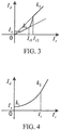
- Frequency-conversion differential protection for the output transformer is implemented by using the biased differential characteristic and according to the magnitudes of the differential current and the restraint current, where the biased differential characteristic may be a bilinear or multi-linear biased characteristic, a dual-slope biased characteristic, or a variable-slope biased characteristic.
- a differential protection operation equation of a bilinear biased characteristic is as follows: ⁇ I d > I s when I r ⁇ I t I d > I s + k ⁇ I r ⁇ I t when I r ⁇ I t where I r is the restraint current, I d is the differential current, I s is the differential protection start-up current, I t is the knee current, and k is the slope coefficient; and split-phase determining is used, and when the operation equation of the formula (3) is met, the differential protection of the output transformeroperate.
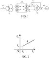
- FIG. 1 three-phase currents on all sides are measured from CTs on high and low voltage sides of an output transformer, and sampling values of the correcting current and the differential current on each side of the output transformer are obtained after phase correction and balance coefficient adjustment are performed on the current on each side of the output transformer according to the connection manner of the output transformer.
- triangle side is used as a reference to perform phase correction on star side; at the same time, in consideration of the secondary rated current on each side of the transformer are different, a balance coefficient on each side is adjusted, so as to calculate the sampling values of the correcting current on each side and the differential current.
- the positive direction is defined as the current on each side flow into the transformer
- sampling values of three-phase currents on high voltage side of the output transformer are set to i Ha ( k ), i Hb ( k ), and i Hc ( k )
- sampling values of three-phase currents on the low voltage side 1 are set to i L1a ( k ), i L1b ( k ), and i L1c ( k )
- i Hb ′ k i Hb k ⁇ i Hc k 3 i Hc ′
- i Ha.j ( k ), i Hb.j ( k ), and i Hc.j ( k ) separately are sampling values of three-phase correcting currents on the high voltage side
- i L 1 a.j ( k ), i L 1 b.j ( k ), and i L 1 c.j ( k ) separately are sampling values of three-phase correcting currents on the low voltage side 1
- i L 2 a . j ( k ), i L 2 b.j ( k ), and i L 2 c.j ( k ) separately are sampling values of three-phase correcting currents on the low voltage side 2.
- amplitude values ( I Ha.j , I Hb.j , and I Hc.j ) of the correcting currents on the high voltage side are calculated by using the sampling values of the correcting currents on the high voltage side; amplitude values ( I L 1 a .
- Frequency-conversion differential protection for the output transformer is implemented by using the biased differential characteristic and according to the magnitudes of the differential current and the restraint current.
- the biased differential characteristic may be a bilinear or multi-linear biased characteristic, a dual-slope biased characteristic, or a variable-slope biased characteristic (see " Gao Chunru. Setting Calculation and Operation Technology of Relay Protection for Large Generator Unit (second edition) [M]. Beijing: China Electric Power Press, 2010 .”) shown in FIG. 2 , FIG. 3, and FIG. 4 .
- a differential protection operation equation is as follows: ⁇ I d > I s when I r ⁇ I t I d > I s + k ⁇ I r ⁇ I t when I r ⁇ I t where I r is the restraint current, I d is the differential current, I s is a differential protection start-up current, I t is a knee current, and k is a slope coefficient.
Landscapes
- Engineering & Computer Science (AREA)
- Power Engineering (AREA)
- Protection Of Transformers (AREA)
- Emergency Protection Circuit Devices (AREA)
- Control Of Eletrric Generators (AREA)
Claims (3)
- Verfahren eines Frequenzwandlungsdifferenzialschutzes für einen Ausgangstransformator (TR2) eines statischen Frequenzwandler(SFC)-Systems, das folgende Schritte umfasst:1) eine Schutzvorrichtung misst Dreiphasenströme auf jeder Seite des Ausgangstransformators (TR2) des SFC-Systems;2) gemäß der Verbindungsweise des Ausgangstransformators (TR2), wird eine Dreiecksseite als eine Referenz zur Durchführung einer Phasenkorrektur auf einer Sternseite verwendet;3) gleichzeitig wird unter Berücksichtigung, dass der Sekundärnennstrom auf jeder Seite des Transformators unterschiedlich ist, ein Ausgleichskoeffizient auf jeder Seite eingestellt, um Abtastwerte einer Korrekturstroms auf jeder Seite und den Differenzstrom zu berechnen;4) ein Generator-Anlauf- und Abschaltschutzalgorithmus, der von der Frequenz nicht beeinflusst wird, wird zum Berechnen von Amplitudenwerten des Korrekturstroms, des Differenzstroms und des Begrenzungsstroms verwendet; und5) ein Frequenzwandlungsdifferenzialschutz für den Ausgangstransformator (TR2) wird unter Verwendung einer vorgespannten Differenzialcharakteristik und gemäß den Beträgen des Differenzstroms und des Begrenzungsstroms implementiert;dadurch gekennzeichnet, dass:in Schritt 3),im Fall einer Y-, d-, d-11-Verbindungsweise des Transformators, ein Verfahren zur Berechnung des Ausgleichskoeffizienten auf jeder Seite dasselbe ist wie bei einem Differenzialschutz eines konventionellen Transformators; und der Ausgleichskoeffizient auf der Hochspannungsseite auf KH gesetzt wird, der Ausgleichskoeffizient auf der Niederspannungsseite 1 auf K L1 gesetzt wird und der Ausgleichskoeffizient auf der Niederspannungsseite 2 auf K L2 gesetzt wird, um iHa.j (k), iHb.j (k) und iHc.j (k) zu erhalten, die separat Abtastwerte der Dreiphasen-Korrekturströme auf der Hochspannungsseite sind, wobei i L1a.j (k), i L1b.j (k) und i L1c.j (k) separat Abtastwerte der Dreiphasen-Korrekturströme auf der Niederspannungsseite 1 sind, und i L2a.j (k), i L2b.j (k), und i L2c.j (k) separat Abtastwerte der Dreiphasen-Korrekturströme auf der Niederspannungsseite 2 sind;in Schritt 4),Dreiphasen-Differenzströme durch Verwenden des Korrekturstroms auf der Hoch- und Niederspannungsseite berechnet werden:
 wobei ida (k), idb (k) und idc (k) separat Abtastwerte der Dreiphasen-Differenzströme sind;durch Verwenden des Generator-Anlauf- und Abschaltschutzalgorithmus, der nicht von der Frequenz beeinflusst wird, Amplitudenwerte IHa.j , IHb.j und IHc.j der Korrekturströme auf der Hochspannungsseite durch Verwenden der Abtastwerte der Korrekturströme auf der Hochspannungsseite berechnet werden; Amplitudenwerte I L1a.j , I L1b.j und I L1c.j der Korrekturströme auf der Niederspannungsseite 1 durch Verwenden der Abtastwerte der Korrekturströme auf der Niederspannungsseite 1 berechnet werden; Amplitudenwerte I L2a.j , I L2b.j und I L2c.j der Korrekturströme auf der Niederspannungsseite 2 durch Verwenden der Abtastwerte der Korrekturströme auf der Niederspannungsseite 2 berechnet werden; und Amplitudenwerte Ida, Idb und Idc der Differenzialströme durch Verwenden der Abtastwerte der Differnzialströme berechnet werden;wobei Begrenzungsströme durch Verwenden der Korrekturströme auf der Hoch- und Niederspannungsseite wie folgt berechnet werden:
 wobei Ira, Irb und Irc separat Dreiphasen-Begrenzungsströme sind;und in Schritt 5),wobei die vorgespannte Differenzialcharakteristik eine bilineare oder multilineare vorgespannte Charakteristik, eine vorgespannte Dual-Slope-Charakteristik oder eine vorgespannte Charakteristik mit variabler Steigung sein kann;die Differenzialschutzbetriebsgleichung einer bilinearen Verhältnis-Begrenzungscharakteristik wie folgt lautet:
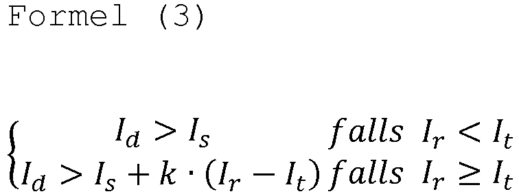 wobei Ir der Begrenzungsstrom ist, Id der Differenzialstrom ist, Is ein Differenzialschutz-Anlaufstrom ist, It ein Kniestrom ist und k ein Steigungskoeffizient ist; undwobei eine Split-Phasen-Bestimmung verwendet wird, und wenn die Betriebsgleichung der Formel (3) erfüllt wird, ein Differenzialschutz des Ausgangstransformators (TR2) wirksam ist.
 - Verfahren eines Frequenzwandlungsdifferenzialschutzes für einen Ausgangstransformator (TR2) eines SFC-Systems nach Anspruch 1, wobei der verwendete Generator-Anlauf- und Abschaltschutzalgorithmus, der nicht von der Frequenz beeinflusst wird, einen Nulldurchgangspunkt-Integralalgorithmus oder ein Stromspitzenwert-Bestimmungsverfahren umfasst.
- Verfahren eines Frequenzwandlungsdifferenzialschutzes für einen Ausgangstransformator (TR2) eines SFC-Systems nach Anspruch 1, wobei die vorgespannte Differenzialcharakteristik eine bilineare oder multilineare vorgespannte Charakteristik, eine vorgespannte Dual-Slope-Charakteristik oder eine vorgespannte Charakteristik mit variabler Steigung umfasst.
Applications Claiming Priority (2)
| Application Number | Priority Date | Filing Date | Title |
|---|---|---|---|
| CN201210332624.4A CN103683195B (zh) | 2012-09-11 | 2012-09-11 | 静止变频器系统输出变压器变频差动保护方法 |
| PCT/CN2013/078552 WO2014040448A1 (zh) | 2012-09-11 | 2013-07-01 | 静止变频器系统输出变压器变频差动保护方法 |
Publications (3)
| Publication Number | Publication Date |
|---|---|
| EP2897243A1 EP2897243A1 (de) | 2015-07-22 |
| EP2897243A4 EP2897243A4 (de) | 2016-05-25 |
| EP2897243B1 true EP2897243B1 (de) | 2019-02-06 |
Family
ID=50277577
Family Applications (1)
| Application Number | Title | Priority Date | Filing Date |
|---|---|---|---|
| EP13837802.1A Active EP2897243B1 (de) | 2012-09-11 | 2013-07-01 | Verfahren für frequenzwandlungsdifferenzialschutz für ausgangstransformator eines statischen frequenzwandlersystems |
Country Status (7)
| Country | Link |
|---|---|
| US (1) | US9640981B2 (de) |
| EP (1) | EP2897243B1 (de) |
| JP (1) | JP6152168B2 (de) |
| KR (1) | KR101998916B1 (de) |
| CN (1) | CN103683195B (de) |
| RU (1) | RU2598903C1 (de) |
| WO (1) | WO2014040448A1 (de) |
Families Citing this family (29)
| Publication number | Priority date | Publication date | Assignee | Title |
|---|---|---|---|---|
| CN104218543B (zh) * | 2013-05-30 | 2016-12-28 | 南京南瑞继保电气有限公司 | 电流源型变流器差动保护方法 |
| CN103887768B (zh) * | 2014-04-09 | 2016-07-06 | 南京保合太和电力科技有限公司 | 励磁系统整流桥差动保护方法及系统 |
| CN104155883B (zh) * | 2014-06-12 | 2016-09-14 | 国家电网公司 | 一种抽水蓄能机组sfc的启动控制方法 |
| CN104124687A (zh) * | 2014-08-08 | 2014-10-29 | 南京南瑞继保电气有限公司 | 一种双sfc系统拓扑结构 |
| DE102014217300A1 (de) * | 2014-08-29 | 2016-03-03 | Siemens Aktiengesellschaft | Anordnung zum Anschließen einer Bahnstromversorgung für eine Bahnstrecke an ein dreiphasiges Versorgungsnetz |
| CN105591768B (zh) * | 2014-10-21 | 2019-11-29 | 中兴通讯股份有限公司 | 故障检测方法及装置 |
| US10310004B2 (en) * | 2015-09-18 | 2019-06-04 | Schweitzer Engineering Laboratories, Inc. | Time-domain differential line protection of electric power delivery systems |
| CN106569035B (zh) * | 2015-10-08 | 2019-02-22 | 南京南瑞继保电气有限公司 | 直接电压补偿的静止变频器同步相位检测方法 |
| CN108139438B (zh) | 2015-10-13 | 2021-03-12 | 施瓦哲工程实验有限公司 | 使用高频信号的电力系统监测 |
| CN105514957B (zh) * | 2016-01-28 | 2017-12-22 | 南京南瑞继保电气有限公司 | 一种混合背靠背直流输电系统及潮流反转控制方法 |
| CN106936111B (zh) * | 2017-04-05 | 2019-01-18 | 南京国电南自维美德自动化有限公司 | 基于拐点跟踪的双曲线制动特性差动保护方法 |
| CN109659902B (zh) * | 2017-10-11 | 2020-03-20 | 南京南瑞继保电气有限公司 | 一种抽水蓄能电站水泵启动过程差动保护方法和装置 |
| RU2683266C1 (ru) * | 2018-01-09 | 2019-03-27 | Федеральное государственное бюджетное образовательное учреждение высшего образования "Тюменский индустриальный университет" (ТИУ) | СПОСОБ ЗАЩИТЫ ПРЕОБРАЗОВАТЕЛЬНОЙ УСТАНОВКИ С ТРАНСФОРМАТОРОМ С 2n ВТОРИЧНЫМИ ОБМОТКАМИ И 2n ВЫПРЯМИТЕЛЯМИ |
| CN108931702B (zh) * | 2018-06-05 | 2021-01-26 | 中国大唐集团科学技术研究院有限公司华中分公司 | 一种励磁系统小电流试验异常判别方法 |
| US10677834B2 (en) | 2018-09-14 | 2020-06-09 | Schweitzer Engineering Laboratories, Inc. | Distance protection of electric power delivery systems using time domain and frequency domain |
| US10641815B2 (en) | 2018-09-27 | 2020-05-05 | Schweitzer Engineering Laboratories, Inc. | Secure distance protection of electric power delivery systems under transient conditions |
| CN110380788B (zh) * | 2019-07-12 | 2020-12-25 | 中国科学院半导体研究所 | 基于微分技术的频率测量装置及采用其的微波接收机 |
| CN111366878B (zh) * | 2020-04-23 | 2025-01-21 | 西安热工研究院有限公司 | 一种校验启备变分支差动保护极性的系统与方法 |
| CN111525509B (zh) * | 2020-06-01 | 2022-05-03 | 攀钢集团西昌钢钒有限公司 | 电力系统的整流变压器及用于其上过电流保护整定方法 |
| CN111751647B (zh) * | 2020-06-24 | 2023-08-08 | 深圳供电局有限公司 | 一种差流异常检测方法 |
| CN112039019B (zh) * | 2020-08-19 | 2022-07-22 | 积成软件有限公司 | 一种识别变压器轻微故障的判别方法 |
| US11735907B2 (en) | 2021-02-03 | 2023-08-22 | Schweitzer Engineering Laboratories, Inc. | Traveling wave overcurrent protection for electric power delivery systems |
| CN113672863B (zh) * | 2021-07-08 | 2024-05-28 | 南京国电南自电网自动化有限公司 | 一种发电机启机保护的简化相量计算方法及系统 |
| CN113740649A (zh) * | 2021-09-03 | 2021-12-03 | 大唐滨州发电有限公司 | 变压器保护装置差动保护比率制动系数k值校验的方法 |
| CN114264901B (zh) * | 2021-12-07 | 2023-08-22 | 广东电网有限责任公司 | 一种变压器区外故障时的平衡电流模拟方法及相关装置 |
| CN114447883B (zh) * | 2021-12-23 | 2024-01-09 | 北京四方继保工程技术有限公司 | 一种抽水蓄能机组变压器差动保护方法 |
| CN114825424A (zh) * | 2022-03-17 | 2022-07-29 | 中国电力科学研究院有限公司 | 一种抽水蓄能机组sfc系统启动控制方法和系统 |
| CN116231589B (zh) * | 2022-11-28 | 2023-09-29 | 云南电网有限责任公司昆明供电局 | 一种无须与电动机启动电流配合的电流速断保护方法 |
| DE102023207228A1 (de) * | 2023-07-28 | 2025-01-30 | Siemens Energy Global GmbH & Co. KG | Expansionskraftwerk und Verfahren zum Betreiben eines solchen Kraftwerks |
Family Cites Families (24)
| Publication number | Priority date | Publication date | Assignee | Title |
|---|---|---|---|---|
| JPS5834597U (ja) * | 1981-08-31 | 1983-03-07 | 株式会社日立製作所 | サイリスタ始動装置 |
| JPS62244218A (ja) * | 1986-04-14 | 1987-10-24 | 株式会社東芝 | 変圧器保護用差動継電装置 |
| JP3447811B2 (ja) * | 1994-07-19 | 2003-09-16 | 株式会社日立製作所 | 受変電設備の変圧器用保護継電システム及び受変電設備の変圧器保護方法 |
| JPH10327530A (ja) * | 1997-05-23 | 1998-12-08 | Mitsubishi Electric Corp | 変圧器保護用比率差動継電器 |
| RU2137277C1 (ru) * | 1998-01-08 | 1999-09-10 | Шинкаренко Сергей Михайлович | Устройство для дифференциального фильтра токов обратной последовательности (i2) трехфазной электрической установки |
| RU2176123C1 (ru) * | 2000-09-13 | 2001-11-20 | Шинкаренко Сергей Михайлович | Способ дифференциальной токовой защиты трехфазного трансформатора и устройство для его реализации |
| JP4112930B2 (ja) * | 2002-09-04 | 2008-07-02 | 東芝三菱電機産業システム株式会社 | インバータ装置 |
| JP2005073324A (ja) * | 2003-08-21 | 2005-03-17 | Tm T & D Kk | 変圧器保護用差動継電装置 |
| JP2005269870A (ja) | 2004-03-22 | 2005-09-29 | Mitsubishi Electric Corp | 比率差動保護装置 |
| DE102006019875B3 (de) | 2006-04-28 | 2007-10-04 | Siemens Ag | Einrichtung zur Sicherung einer unterbrechungsfreien Stromversorgung eines Magnetlagers bei Ausfall einer elektrischen Versorgungsspannung |
| CN100550557C (zh) * | 2006-12-19 | 2009-10-14 | 北京四方继保自动化股份有限公司 | 大型电力变压器负序电流差动保护方法 |
| US7738221B2 (en) * | 2007-12-07 | 2010-06-15 | Cooper Technologies Company | Transformer inrush current detector |
| CN201312282Y (zh) * | 2008-11-25 | 2009-09-16 | 上海新华控制技术(集团)有限公司 | 静止变频器调速系统 |
| CN101430358B (zh) * | 2008-12-10 | 2010-12-22 | 河南国网宝泉抽水蓄能有限公司 | 抽水蓄能电站首机首次水泵工况整组启动试验方法 |
| CN101483332B (zh) * | 2009-02-10 | 2011-01-12 | 国电南瑞科技股份有限公司 | 采样值差流启动的相量差动保护方法 |
| JP5534753B2 (ja) | 2009-09-11 | 2014-07-02 | 株式会社東芝 | 変圧器の保護方式とその装置 |
| CN101710691B (zh) | 2009-09-30 | 2012-07-04 | 中国水电顾问集团华东勘测设计研究院 | 用于消除抽蓄电站发电电动机和主变压器保护死区的装置 |
| CN101976820A (zh) * | 2010-08-31 | 2011-02-16 | 南京南瑞继保电气有限公司 | 变频电动机保护采样信号处理方法 |
| CN101958530A (zh) * | 2010-10-26 | 2011-01-26 | 湖北白莲河抽水蓄能有限公司 | 抽水蓄能电站主变压器差动保护ct极性校验方法 |
| WO2012113455A1 (en) | 2011-02-25 | 2012-08-30 | Abb Technology Ag | A method for obtaining an instantaneous direct current value, and control device |
| CN102129006A (zh) * | 2011-03-01 | 2011-07-20 | 宁波市鄞州供电局 | 一种微机型变压器差动保护二次接线错误检测方法 |
| CN102983587B (zh) * | 2011-09-07 | 2015-01-07 | 台达电子企业管理(上海)有限公司 | 具有超速保护的风力发电系统及其操作方法 |
| CN102695343B (zh) * | 2012-06-06 | 2014-01-29 | 矽力杰半导体技术(杭州)有限公司 | 一种led驱动电路 |
| CN104242605B (zh) * | 2013-06-07 | 2016-08-10 | 台达电子工业股份有限公司 | 均流母排 |
-
2012
- 2012-09-11 CN CN201210332624.4A patent/CN103683195B/zh active Active
-
2013
- 2013-07-01 JP JP2015530272A patent/JP6152168B2/ja active Active
- 2013-07-01 WO PCT/CN2013/078552 patent/WO2014040448A1/zh not_active Ceased
- 2013-07-01 EP EP13837802.1A patent/EP2897243B1/de active Active
- 2013-07-01 US US14/426,873 patent/US9640981B2/en active Active
- 2013-07-01 KR KR1020157006077A patent/KR101998916B1/ko active Active
- 2013-07-01 RU RU2015112668/07A patent/RU2598903C1/ru active
Non-Patent Citations (1)
| Title |
|---|
| None * |
Also Published As
| Publication number | Publication date |
|---|---|
| KR20150054815A (ko) | 2015-05-20 |
| RU2598903C1 (ru) | 2016-10-10 |
| CN103683195B (zh) | 2016-12-21 |
| JP6152168B2 (ja) | 2017-06-21 |
| US9640981B2 (en) | 2017-05-02 |
| EP2897243A4 (de) | 2016-05-25 |
| KR101998916B1 (ko) | 2019-07-10 |
| CN103683195A (zh) | 2014-03-26 |
| EP2897243A1 (de) | 2015-07-22 |
| JP2015529444A (ja) | 2015-10-05 |
| US20150255978A1 (en) | 2015-09-10 |
| WO2014040448A1 (zh) | 2014-03-20 |
Similar Documents
| Publication | Publication Date | Title |
|---|---|---|
| EP2897243A1 (de) | Verfahren für frequenzwandlungsdifferenzialschutz für ausgangstransformator eines statischen frequenzwandlersystems | |
| US8878546B2 (en) | Apparatus and method for quickly determining fault in electric power system | |
| EP3007294B1 (de) | Differenzialschutzverfahren für stromquellenumrichter und relaisschutzvorrichtung | |
| US20230178989A1 (en) | Current Control Method and System for Voltage Asymmetry Fault | |
| US10393810B2 (en) | Method for identifying the fault by current differential protection and device thereof | |
| EP4312335B1 (de) | Wandler, netzstromversorgungssystem und wandlersteuerungsverfahren | |
| Abdulwahid et al. | A new differential protection scheme for microgrid using Hilbert space based power setting and fuzzy decision processes | |
| CN107045116A (zh) | 一种发电机保护的电流互感器极性检测方法及装置 | |
| CN105931823A (zh) | 电压互感器消谐电阻自动跟踪调整的方法 | |
| CN104215897A (zh) | 利用端口电压之间的相位差判断断路器非全相的方法 | |
| EP3185407A1 (de) | Dc/ac umrichter mit lvrt regelung | |
| EP3416259B1 (de) | Verfahren zur steuerung der nullspannung eines spannungsquellenumrichters | |
| EP3306333B1 (de) | Differenzfehlererkennungssystem | |
| CN101106266A (zh) | 一种基于导纳原理实现变压器保护的方法 | |
| CN103887768B (zh) | 励磁系统整流桥差动保护方法及系统 | |
| CN103779835A (zh) | 基于铁耗无功功率特性变压器绕组匝间短路继电保护方法 | |
| CN108680825B (zh) | 一种基于综合序阻抗的孤岛检测方法 | |
| CN112557957B (zh) | 一种磁控式可控并联电抗器pt断线判断方法、装置及系统 | |
| Bimenyimana et al. | Fault ride-through (FRT) behavior in VSC-HVDC as key enabler of transmission systems using SCADA viewer software | |
| US20250247014A1 (en) | Power converter and power converter control method | |
| CN104934946B (zh) | 交流滤波器的过载保护系统及其方法 | |
| CN112260224B (zh) | 一种适用于保测一体ct的过流保护装置及方法 | |
| Prince et al. | Resilient bus-bar protection scheme for DC microgrids connected to AC electric grids | |
| CN209280898U (zh) | 一种高压变频器输入电源缺相检测器 | |
| CN117538674A (zh) | 一种适用于柔直接入的不对称短路识别方法 |
Legal Events
| Date | Code | Title | Description |
|---|---|---|---|
| PUAI | Public reference made under article 153(3) epc to a published international application that has entered the european phase |
Free format text: ORIGINAL CODE: 0009012 |
|
| 17P | Request for examination filed |
Effective date: 20150407 |
|
| AK | Designated contracting states |
Kind code of ref document: A1 Designated state(s): AL AT BE BG CH CY CZ DE DK EE ES FI FR GB GR HR HU IE IS IT LI LT LU LV MC MK MT NL NO PL PT RO RS SE SI SK SM TR |
|
| AX | Request for extension of the european patent |
Extension state: BA ME |
|
| DAX | Request for extension of the european patent (deleted) | ||
| RIC1 | Information provided on ipc code assigned before grant |
Ipc: H02H 7/045 20060101AFI20160414BHEP |
|
| RA4 | Supplementary search report drawn up and despatched (corrected) |
Effective date: 20160421 |
|
| GRAP | Despatch of communication of intention to grant a patent |
Free format text: ORIGINAL CODE: EPIDOSNIGR1 |
|
| STAA | Information on the status of an ep patent application or granted ep patent |
Free format text: STATUS: GRANT OF PATENT IS INTENDED |
|
| INTG | Intention to grant announced |
Effective date: 20180820 |
|
| GRAS | Grant fee paid |
Free format text: ORIGINAL CODE: EPIDOSNIGR3 |
|
| GRAA | (expected) grant |
Free format text: ORIGINAL CODE: 0009210 |
|
| STAA | Information on the status of an ep patent application or granted ep patent |
Free format text: STATUS: THE PATENT HAS BEEN GRANTED |
|
| AK | Designated contracting states |
Kind code of ref document: B1 Designated state(s): AL AT BE BG CH CY CZ DE DK EE ES FI FR GB GR HR HU IE IS IT LI LT LU LV MC MK MT NL NO PL PT RO RS SE SI SK SM TR |
|
| REG | Reference to a national code |
Ref country code: GB Ref legal event code: FG4D |
|
| REG | Reference to a national code |
Ref country code: CH Ref legal event code: EP Ref country code: AT Ref legal event code: REF Ref document number: 1095461 Country of ref document: AT Kind code of ref document: T Effective date: 20190215 |
|
| REG | Reference to a national code |
Ref country code: DE Ref legal event code: R096 Ref document number: 602013050601 Country of ref document: DE |
|
| REG | Reference to a national code |
Ref country code: IE Ref legal event code: FG4D |
|
| REG | Reference to a national code |
Ref country code: NL Ref legal event code: MP Effective date: 20190206 |
|
| REG | Reference to a national code |
Ref country code: LT Ref legal event code: MG4D |
|
| PG25 | Lapsed in a contracting state [announced via postgrant information from national office to epo] |
Ref country code: NL Free format text: LAPSE BECAUSE OF FAILURE TO SUBMIT A TRANSLATION OF THE DESCRIPTION OR TO PAY THE FEE WITHIN THE PRESCRIBED TIME-LIMIT Effective date: 20190206 Ref country code: LT Free format text: LAPSE BECAUSE OF FAILURE TO SUBMIT A TRANSLATION OF THE DESCRIPTION OR TO PAY THE FEE WITHIN THE PRESCRIBED TIME-LIMIT Effective date: 20190206 Ref country code: NO Free format text: LAPSE BECAUSE OF FAILURE TO SUBMIT A TRANSLATION OF THE DESCRIPTION OR TO PAY THE FEE WITHIN THE PRESCRIBED TIME-LIMIT Effective date: 20190506 Ref country code: FI Free format text: LAPSE BECAUSE OF FAILURE TO SUBMIT A TRANSLATION OF THE DESCRIPTION OR TO PAY THE FEE WITHIN THE PRESCRIBED TIME-LIMIT Effective date: 20190206 Ref country code: PT Free format text: LAPSE BECAUSE OF FAILURE TO SUBMIT A TRANSLATION OF THE DESCRIPTION OR TO PAY THE FEE WITHIN THE PRESCRIBED TIME-LIMIT Effective date: 20190606 Ref country code: SE Free format text: LAPSE BECAUSE OF FAILURE TO SUBMIT A TRANSLATION OF THE DESCRIPTION OR TO PAY THE FEE WITHIN THE PRESCRIBED TIME-LIMIT Effective date: 20190206 |
|
| REG | Reference to a national code |
Ref country code: AT Ref legal event code: MK05 Ref document number: 1095461 Country of ref document: AT Kind code of ref document: T Effective date: 20190206 |
|
| PG25 | Lapsed in a contracting state [announced via postgrant information from national office to epo] |
Ref country code: HR Free format text: LAPSE BECAUSE OF FAILURE TO SUBMIT A TRANSLATION OF THE DESCRIPTION OR TO PAY THE FEE WITHIN THE PRESCRIBED TIME-LIMIT Effective date: 20190206 Ref country code: RS Free format text: LAPSE BECAUSE OF FAILURE TO SUBMIT A TRANSLATION OF THE DESCRIPTION OR TO PAY THE FEE WITHIN THE PRESCRIBED TIME-LIMIT Effective date: 20190206 Ref country code: GR Free format text: LAPSE BECAUSE OF FAILURE TO SUBMIT A TRANSLATION OF THE DESCRIPTION OR TO PAY THE FEE WITHIN THE PRESCRIBED TIME-LIMIT Effective date: 20190507 Ref country code: IS Free format text: LAPSE BECAUSE OF FAILURE TO SUBMIT A TRANSLATION OF THE DESCRIPTION OR TO PAY THE FEE WITHIN THE PRESCRIBED TIME-LIMIT Effective date: 20190606 Ref country code: LV Free format text: LAPSE BECAUSE OF FAILURE TO SUBMIT A TRANSLATION OF THE DESCRIPTION OR TO PAY THE FEE WITHIN THE PRESCRIBED TIME-LIMIT Effective date: 20190206 Ref country code: BG Free format text: LAPSE BECAUSE OF FAILURE TO SUBMIT A TRANSLATION OF THE DESCRIPTION OR TO PAY THE FEE WITHIN THE PRESCRIBED TIME-LIMIT Effective date: 20190506 |
|
| PG25 | Lapsed in a contracting state [announced via postgrant information from national office to epo] |
Ref country code: EE Free format text: LAPSE BECAUSE OF FAILURE TO SUBMIT A TRANSLATION OF THE DESCRIPTION OR TO PAY THE FEE WITHIN THE PRESCRIBED TIME-LIMIT Effective date: 20190206 Ref country code: SK Free format text: LAPSE BECAUSE OF FAILURE TO SUBMIT A TRANSLATION OF THE DESCRIPTION OR TO PAY THE FEE WITHIN THE PRESCRIBED TIME-LIMIT Effective date: 20190206 Ref country code: RO Free format text: LAPSE BECAUSE OF FAILURE TO SUBMIT A TRANSLATION OF THE DESCRIPTION OR TO PAY THE FEE WITHIN THE PRESCRIBED TIME-LIMIT Effective date: 20190206 Ref country code: CZ Free format text: LAPSE BECAUSE OF FAILURE TO SUBMIT A TRANSLATION OF THE DESCRIPTION OR TO PAY THE FEE WITHIN THE PRESCRIBED TIME-LIMIT Effective date: 20190206 Ref country code: ES Free format text: LAPSE BECAUSE OF FAILURE TO SUBMIT A TRANSLATION OF THE DESCRIPTION OR TO PAY THE FEE WITHIN THE PRESCRIBED TIME-LIMIT Effective date: 20190206 Ref country code: AL Free format text: LAPSE BECAUSE OF FAILURE TO SUBMIT A TRANSLATION OF THE DESCRIPTION OR TO PAY THE FEE WITHIN THE PRESCRIBED TIME-LIMIT Effective date: 20190206 Ref country code: IT Free format text: LAPSE BECAUSE OF FAILURE TO SUBMIT A TRANSLATION OF THE DESCRIPTION OR TO PAY THE FEE WITHIN THE PRESCRIBED TIME-LIMIT Effective date: 20190206 Ref country code: DK Free format text: LAPSE BECAUSE OF FAILURE TO SUBMIT A TRANSLATION OF THE DESCRIPTION OR TO PAY THE FEE WITHIN THE PRESCRIBED TIME-LIMIT Effective date: 20190206 |
|
| REG | Reference to a national code |
Ref country code: DE Ref legal event code: R097 Ref document number: 602013050601 Country of ref document: DE |
|
| PG25 | Lapsed in a contracting state [announced via postgrant information from national office to epo] |
Ref country code: PL Free format text: LAPSE BECAUSE OF FAILURE TO SUBMIT A TRANSLATION OF THE DESCRIPTION OR TO PAY THE FEE WITHIN THE PRESCRIBED TIME-LIMIT Effective date: 20190206 Ref country code: SM Free format text: LAPSE BECAUSE OF FAILURE TO SUBMIT A TRANSLATION OF THE DESCRIPTION OR TO PAY THE FEE WITHIN THE PRESCRIBED TIME-LIMIT Effective date: 20190206 |
|
| PLBE | No opposition filed within time limit |
Free format text: ORIGINAL CODE: 0009261 |
|
| STAA | Information on the status of an ep patent application or granted ep patent |
Free format text: STATUS: NO OPPOSITION FILED WITHIN TIME LIMIT |
|
| PG25 | Lapsed in a contracting state [announced via postgrant information from national office to epo] |
Ref country code: AT Free format text: LAPSE BECAUSE OF FAILURE TO SUBMIT A TRANSLATION OF THE DESCRIPTION OR TO PAY THE FEE WITHIN THE PRESCRIBED TIME-LIMIT Effective date: 20190206 |
|
| 26N | No opposition filed |
Effective date: 20191107 |
|
| PG25 | Lapsed in a contracting state [announced via postgrant information from national office to epo] |
Ref country code: SI Free format text: LAPSE BECAUSE OF FAILURE TO SUBMIT A TRANSLATION OF THE DESCRIPTION OR TO PAY THE FEE WITHIN THE PRESCRIBED TIME-LIMIT Effective date: 20190206 Ref country code: MC Free format text: LAPSE BECAUSE OF FAILURE TO SUBMIT A TRANSLATION OF THE DESCRIPTION OR TO PAY THE FEE WITHIN THE PRESCRIBED TIME-LIMIT Effective date: 20190206 |
|
| REG | Reference to a national code |
Ref country code: CH Ref legal event code: PL |
|
| GBPC | Gb: european patent ceased through non-payment of renewal fee |
Effective date: 20190701 |
|
| PG25 | Lapsed in a contracting state [announced via postgrant information from national office to epo] |
Ref country code: TR Free format text: LAPSE BECAUSE OF FAILURE TO SUBMIT A TRANSLATION OF THE DESCRIPTION OR TO PAY THE FEE WITHIN THE PRESCRIBED TIME-LIMIT Effective date: 20190206 |
|
| REG | Reference to a national code |
Ref country code: BE Ref legal event code: MM Effective date: 20190731 |
|
| PG25 | Lapsed in a contracting state [announced via postgrant information from national office to epo] |
Ref country code: GB Free format text: LAPSE BECAUSE OF NON-PAYMENT OF DUE FEES Effective date: 20190701 |
|
| PG25 | Lapsed in a contracting state [announced via postgrant information from national office to epo] |
Ref country code: CH Free format text: LAPSE BECAUSE OF NON-PAYMENT OF DUE FEES Effective date: 20190731 Ref country code: BE Free format text: LAPSE BECAUSE OF NON-PAYMENT OF DUE FEES Effective date: 20190731 Ref country code: LI Free format text: LAPSE BECAUSE OF NON-PAYMENT OF DUE FEES Effective date: 20190731 Ref country code: LU Free format text: LAPSE BECAUSE OF NON-PAYMENT OF DUE FEES Effective date: 20190701 |
|
| PG25 | Lapsed in a contracting state [announced via postgrant information from national office to epo] |
Ref country code: IE Free format text: LAPSE BECAUSE OF NON-PAYMENT OF DUE FEES Effective date: 20190701 |
|
| PG25 | Lapsed in a contracting state [announced via postgrant information from national office to epo] |
Ref country code: CY Free format text: LAPSE BECAUSE OF FAILURE TO SUBMIT A TRANSLATION OF THE DESCRIPTION OR TO PAY THE FEE WITHIN THE PRESCRIBED TIME-LIMIT Effective date: 20190206 |
|
| PG25 | Lapsed in a contracting state [announced via postgrant information from national office to epo] |
Ref country code: MT Free format text: LAPSE BECAUSE OF FAILURE TO SUBMIT A TRANSLATION OF THE DESCRIPTION OR TO PAY THE FEE WITHIN THE PRESCRIBED TIME-LIMIT Effective date: 20190206 Ref country code: HU Free format text: LAPSE BECAUSE OF FAILURE TO SUBMIT A TRANSLATION OF THE DESCRIPTION OR TO PAY THE FEE WITHIN THE PRESCRIBED TIME-LIMIT; INVALID AB INITIO Effective date: 20130701 |
|
| PG25 | Lapsed in a contracting state [announced via postgrant information from national office to epo] |
Ref country code: MK Free format text: LAPSE BECAUSE OF FAILURE TO SUBMIT A TRANSLATION OF THE DESCRIPTION OR TO PAY THE FEE WITHIN THE PRESCRIBED TIME-LIMIT Effective date: 20190206 |
|
| PGFP | Annual fee paid to national office [announced via postgrant information from national office to epo] |
Ref country code: DE Payment date: 20250711 Year of fee payment: 13 |
|
| PGFP | Annual fee paid to national office [announced via postgrant information from national office to epo] |
Ref country code: FR Payment date: 20250730 Year of fee payment: 13 |