EP2897230A1 - Connection électrique notamment pour un system de chauffage d'un vehicule - Google Patents
Connection électrique notamment pour un system de chauffage d'un vehicule Download PDFInfo
- Publication number
- EP2897230A1 EP2897230A1 EP14000208.0A EP14000208A EP2897230A1 EP 2897230 A1 EP2897230 A1 EP 2897230A1 EP 14000208 A EP14000208 A EP 14000208A EP 2897230 A1 EP2897230 A1 EP 2897230A1
- Authority
- EP
- European Patent Office
- Prior art keywords
- contact
- sheet
- tongue
- spring tongues
- electrical
- Prior art date
- Legal status (The legal status is an assumption and is not a legal conclusion. Google has not performed a legal analysis and makes no representation as to the accuracy of the status listed.)
- Granted
Links
- 238000010438 heat treatment Methods 0.000 title claims description 29
- 210000002105 tongue Anatomy 0.000 claims abstract description 137
- 239000002184 metal Substances 0.000 claims abstract description 26
- 238000005485 electric heating Methods 0.000 claims abstract description 5
- 239000004020 conductor Substances 0.000 claims description 4
- 238000011144 upstream manufacturing Methods 0.000 claims description 3
- 239000012777 electrically insulating material Substances 0.000 claims 1
- 238000003780 insertion Methods 0.000 description 13
- 230000037431 insertion Effects 0.000 description 13
- 239000011265 semifinished product Substances 0.000 description 9
- 238000005452 bending Methods 0.000 description 5
- 238000012545 processing Methods 0.000 description 5
- 238000004080 punching Methods 0.000 description 5
- 239000007787 solid Substances 0.000 description 5
- 238000013461 design Methods 0.000 description 4
- 230000005540 biological transmission Effects 0.000 description 3
- 238000004519 manufacturing process Methods 0.000 description 3
- 230000007704 transition Effects 0.000 description 3
- 235000014676 Phragmites communis Nutrition 0.000 description 2
- 238000011161 development Methods 0.000 description 2
- 241000196324 Embryophyta Species 0.000 description 1
- 244000089486 Phragmites australis subsp australis Species 0.000 description 1
- 238000005520 cutting process Methods 0.000 description 1
- 238000005553 drilling Methods 0.000 description 1
- 239000012530 fluid Substances 0.000 description 1
- 238000007373 indentation Methods 0.000 description 1
- 238000009434 installation Methods 0.000 description 1
- 238000005304 joining Methods 0.000 description 1
- 239000007788 liquid Substances 0.000 description 1
- 239000000463 material Substances 0.000 description 1
- 239000002991 molded plastic Substances 0.000 description 1
- 238000004886 process control Methods 0.000 description 1
- 230000002250 progressing effect Effects 0.000 description 1
- 230000000750 progressive effect Effects 0.000 description 1
- 230000000284 resting effect Effects 0.000 description 1
- 238000000926 separation method Methods 0.000 description 1
- 238000005728 strengthening Methods 0.000 description 1
Images


Classifications
-
- H—ELECTRICITY
- H01—ELECTRIC ELEMENTS
- H01R—ELECTRICALLY-CONDUCTIVE CONNECTIONS; STRUCTURAL ASSOCIATIONS OF A PLURALITY OF MUTUALLY-INSULATED ELECTRICAL CONNECTING ELEMENTS; COUPLING DEVICES; CURRENT COLLECTORS
- H01R13/00—Details of coupling devices of the kinds covered by groups H01R12/70 or H01R24/00 - H01R33/00
- H01R13/02—Contact members
- H01R13/04—Pins or blades for co-operation with sockets
- H01R13/05—Resilient pins or blades
- H01R13/055—Resilient pins or blades co-operating with sockets having a rectangular transverse section
-
- H—ELECTRICITY
- H01—ELECTRIC ELEMENTS
- H01R—ELECTRICALLY-CONDUCTIVE CONNECTIONS; STRUCTURAL ASSOCIATIONS OF A PLURALITY OF MUTUALLY-INSULATED ELECTRICAL CONNECTING ELEMENTS; COUPLING DEVICES; CURRENT COLLECTORS
- H01R12/00—Structural associations of a plurality of mutually-insulated electrical connecting elements, specially adapted for printed circuits, e.g. printed circuit boards [PCB], flat or ribbon cables, or like generally planar structures, e.g. terminal strips, terminal blocks; Coupling devices specially adapted for printed circuits, flat or ribbon cables, or like generally planar structures; Terminals specially adapted for contact with, or insertion into, printed circuits, flat or ribbon cables, or like generally planar structures
- H01R12/70—Coupling devices
- H01R12/71—Coupling devices for rigid printing circuits or like structures
- H01R12/72—Coupling devices for rigid printing circuits or like structures coupling with the edge of the rigid printed circuits or like structures
- H01R12/73—Coupling devices for rigid printing circuits or like structures coupling with the edge of the rigid printed circuits or like structures connecting to other rigid printed circuits or like structures
-
- H—ELECTRICITY
- H01—ELECTRIC ELEMENTS
- H01R—ELECTRICALLY-CONDUCTIVE CONNECTIONS; STRUCTURAL ASSOCIATIONS OF A PLURALITY OF MUTUALLY-INSULATED ELECTRICAL CONNECTING ELEMENTS; COUPLING DEVICES; CURRENT COLLECTORS
- H01R2201/00—Connectors or connections adapted for particular applications
- H01R2201/26—Connectors or connections adapted for particular applications for vehicles
Definitions
- the present invention relates to an electrical plug-in connection between a printed circuit board provided with at least one connection piece and a contact tongue made of a sheet metal which can be introduced through a recess in the printed circuit board to the connection piece.
- the present invention relates to an electrical connector of this type in an electrical heating device for a motor vehicle.
- Such an electric heating device for a motor vehicle usually has at least one PTC heating element with contact plates which are aligned substantially parallel to one another and receive a PTC element between them. It is the present invention to the electrical contact of these contact plates to a circuit board.
- the electrical heating device with the electrical plug connection according to the invention can also have a connection board for connecting different PTC heating elements to strip conductors and another populated control circuit board, in which control signals for driving the PTC heating elements are processed and passed on to the connection board.
- the electrical connection of the control circuit board to the terminal board is carried out via the electrical connector according to the invention.
- An electric heater for a motor vehicle of the type mentioned is for example from the EP 1 931 176 B1 described above using the example of a heater for heating liquid fluid.
- the control circuit board extends at right angles to the terminal board and is provided in a separate control housing.
- An electric heater of the type mentioned for a motor vehicle can also, for example, as a PTC heater for air heating such as in EP 0 901 311 A1 and EP 1 157 867 B1 be described described.
- each first spring tongue projects from a first longitudinal side of the recess into it, whereas each second spring tongue projects from the opposite longitudinal side into the recess.
- a contact tongue For electrical contacting a contact tongue is inserted into the recess, which protrudes between the opposite spring tongues, so that the spring tongues abut against opposing surfaces on the contact tongue and hereby provide a solid electrical contact, which is made compact, since the female connector only with its flange Mounting portion rests on a surface of the circuit board, but otherwise is located in the recess of the circuit board.
- the present invention wants from the EP 2 236 330 B1 improve known electrical connector.
- the contact tongue has at least one lifted out of the plane of the sheet, in the longitudinal direction of the contact tongue extending contact surface, at the top in the inserted state at least one of the spring tongues rests.
- the contact tongue of the electrical according to the invention Plug connection a contouring.
- the sheet is usually modified by forming to form the raised contact surface.
- the present invention proposes at least three spring tongues in the longitudinal direction of the recess one behind the other.
- the middle of these three spring tongues is provided on one side, the two outer spring tongues of this group of three on the other side of the preferably elongated recess.
- the two outer spring tongues cooperate with corresponding contact surfaces of the sheet, which is provided on a different plane than the contact surface of the sheet cooperating with the central contact tongue.
- the cooperating with the two outer spring tongues of the triplet contact surfaces of the sheet may be formed by unmodified surfaces of the original flat sheet semifinished product or be the same by reshaping raised from this plane contact surfaces.
- the cooperating with the middle spring tongue contact surface of the sheet is formed in each case in other ways, that is formed in the first case by a particular raised by forming lifted contact surface or by the normal, ie not formed surface of the flat sheet semifinished product.
- a solid contact is achieved by which the contact tongue on the one hand solidly supported and on the other hand is applied with good pressure to the spring tongues of the connector.
- It can also be several triplets too a single recess and a contact tongue provided corresponding thereto.
- the groups of three can each share the outer spring tongues with respect to the connecting piece and the outer contact surfaces with respect to the contact tongue. In this case, therefore, the last spring tongue of the first group of three is the first spring tongue of the following, provided in the longitudinal direction of the recess behind the triad.
- the contact surface lifted out of the plane of the sheet through the upper side of a contact rib is formed by forming the sheet, in particular by deep drawing of the sheet.
- the system extends in the longitudinal direction of the contact tongue.
- the longitudinal direction is identical to the insertion of the contact tongue in the female connector during manufacture of the electrical connector, hereinafter also referred plugging direction.
- the contact tongue has a front portion which limits the contact tongue end, ie at its free end face.
- This front section is preceded by at least one raised contact surface.
- the raised contact surface preferably connects directly to the front section.
- the front portion has top and bottom surfaces disposed between the contact surfaces formed on the top and bottom of the panel. Consequently, the front section is usually located with its upper and lower surfaces in each case at a distance from the arranged on the top and bottom of the sheet contact surfaces or these contact surfaces containing levels.
- the surface of the contact portion has the same height distance to a plane containing the contact surface at the top as the bottom surface to a formed on the underside of the sheet contact surface or a plane containing them.
- the front portion end with a phase.
- the free end of the reed i. the free end of the front section also be rounded only.
- the contact tongue is integrally formed on a metal sheet, which forms a sheet metal base greater width than the contact tongue.
- This sheet metal base is surmounted by the contact tongue end.
- connection lands are separated to form electrically isolated regions of a printed circuit board consisting of the embossed and trimmed sheet and the support board fixed to the support board.
- the sheet metal base preferably forms a stamped metal plate, as described in more detail as part of a printed circuit board in the present applicant EP 2 505 931 A1 is described. All details disclosed there to the metal plate described there can further develop the sheet of the present invention. By referring to the earlier disclosure, its content is incorporated into the content of the present application. The same applies to those in the EP 2 505 931 A1 described details of the support plate, which is made in particular as an injection-molded plastic part and, for example, later added to the punched sheet metal.
- the spring tongues are punctiform on the sheet. This is usually achieved in that the spring tongues are each punched.
- a line-shaped impression is provided on the spring tongue, which is provided on a usually convex contact surface of the spring tongue and projects beyond this flat surface in the manner of a ridge.
- the present invention further provides an electrical heating device for a motor vehicle under protection.
- the electrical heating device has at least one PTC heating element with contact plates aligned substantially parallel to one another and accommodating at least one PTC element between them.
- the electrical heating device has a printed circuit board which forms at least one recess which is penetrated by a contact tongue formed by a contact sheet for the electrical connection of the PTC heating element to the printed circuit board.
- This printed circuit board is used to connect usually several PTC heating elements and is therefore referred to as a connection board.
- this electric heater has an electrical connector previously described in relation to the present invention.
- the connector is provided between the contact tongue of the PTC heating element and the terminal board.
- the electrical connector can also be provided between this terminal board and a populated control circuit board.
- the populated control circuit board is equipped with electrical or electronic components and passes on the control circuit board controlled power current to the terminal board on.
- the sheet is usually formed as a uniform punched / bent part with the fittings formed therein and then connected to the insulating support plate.
- control circuit board defines various heating circuits to the PTC heating element, i. can selectively drive differently grouped PTC heating elements of the electric heater.
- power current for typically grouped PTC heating elements can usually be modulated by means of PWM (Pulse Width Modulation) and thus the electrical power of individual heating stages or of all PTC heating elements of the electric heating device can be varied.
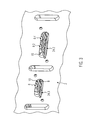
- FIGS. 1 and 2 show a marked with reference numeral 2 Steuerleiterplatte.
- This control circuit board 2 is equipped with electrical or electronic components and is used to process control signals. It has a plurality of interconnects which serve, among other things, the connection to a power connector or a control connector, which in each case forward the power current and control signals to the control circuit board 2.
- the printed conductors, not shown, of the control circuit board 2 are electrically connected to connecting pieces 4.
- These fittings 4 have a mounting portion 6, the flange-shaped and on the in the insertion direction (arrow E in Fig. 1 ) front surface of the control circuit board 2 and a plurality of spring tongues 8, which are fixed to the mounting portion 6 and project into a recess 10 of the control circuit board 2.
- the spring tongues 8 are in the in EP 2 236 330 B1 described manner formed by punching and bending from a sheet. They extend within the recess 10, but usually do not tower over this. Likewise in EP 2 236 330 B1 described, the connector 4 at longitudinally opposite ends holding webs 12, which are introduced into a separate bore 14 of the control circuit board 2.
- the control circuit board 2 is upstream in the FIGS. 1 and 2 an end portion of a terminal board 16 is shown.
- This terminal board 16 has a plurality of electrically separate line paths, which are formed by a stamped sheet 18, as shown in the EP 2 505 931 A1 the present applicant is described.
- FIG. 1 lacks a this sheet 18 underside supporting insulating formed support plate. In fact, the plate 18 and the carrier plate are intimately connected.
- FIGS. 1 and 2 are still separators 22 to recognize which are initially allowed to stand in the punching processing of the sheet 18 to connect the plate 18 as a stable unit with the support plate. These dividers 22 are severed after connection to define different conduction paths through the sheet 18.
- Each individual conduction path is provided in the embodiment shown with a contact tongue 24, which projects beyond the support plate end.
- the contact tongues 24 are also formed in the sheet metal processing of the sheet 18 (punching and bending) and integrally formed on the plate 18.
- the contact tongues 24 have a width which is smaller than the width of an elongated receiving opening 26 of the elongate connecting pieces 4.
- FIGS. 4 to 7 Details of the respective connection piece 4 and the contact tongue 24 are in particular the FIGS. 4 to 7 to which reference is made below.
- the FIGS. 4 to 6 show increases the inserted state FIG. 2 for the embodiment shown and for the reference numerals 4.2 and 24.2 in the FIGS. 1 and 2 marked plug-in elements of the electrical connector.
- This contact tongue 24 is - as already mentioned above - formed as an integral part of the sheet 18.
- underside 28 shown forms three parallel in the direction of insertion E extending lower contact surfaces 30.1 to 30.3.
- these lower contact surfaces 30 lie in a plane which lies through the original surface of the unprocessed, ie flat semi-finished product, as which the sheet 18 initially supplied (hereinafter semi-finished plane E1) is.
- semi-finished plane E1 the sheet 18 initially supplied
- a circumferential ramp surface 38 leading to the raised contact surfaces 36 is formed on the upper side 34.
- the raised contact surfaces 36 of all abutment ribs 32 lie on a raised plane, the in FIG. 6 is marked with E3 and which projects beyond a projected semi-finished plane E2 of the sheet 18.
- This projected semifinished product plane E2 is defined by an original surface of the semifinished material before the bending treatment.
- the contact surfaces 30 formed on the underside 28 by the surface of the sheet metal semifinished product lie on the raised plane E3 opposite Semifinished product level E1.
- a marked with reference numeral 44 front portion As part of the sheet metal processing is characterized in deep drawing a marked with reference numeral 44 front portion, so that the front portion 44 parallel to the two planes E1, E3, but with its upper and lower surfaces 46; 48 is located between these two levels E1, E3. Due to the bending processing, a further ramp surface 50 is also formed on the underside 28 at the transition between the front section 44 and the semi-finished plane 42.
- the free end of the front portion 44 that is, the front end of the contact tongue 24 is rounded in the embodiment shown.
- the surface 46 has the same distance to the raised plane E3 as the lower surface 48 to the semi-finished plane E1.
- FIGS. 4 and 5 Let next to the contact tongues 24 also on the sheet 18 formed stiffening ribs 52 which overlap in the longitudinal direction partially with the abutment ribs 32 and stiffen the plate 18 in the region of relatively large-scale punched-out recesses 54.
- stiffening ribs 52 which overlap in the longitudinal direction partially with the abutment ribs 32 and stiffen the plate 18 in the region of relatively large-scale punched-out recesses 54.
- the contact tongue 24.2 abutment ribs 32 extend into a widened base 60 of the sheet 18, which is surmounted by the contact tongue 24.
- the stiffening rib 52 stiffens the metal sheet 18 in the region of the punched-out recess 54.
- FIGS. 4 and 5 also clarify details of the connector 4.2 as shown in the FIGS. 1 and 2 ,
- This connector 4.2 has five spring tongues 8.1 to 8.5.
- Those with reference numbers 8.2 and 8.4 in FIG. 4 characterized spring tongues protrude from a first longitudinal side into the elongate recess 10; the marked with reference numerals 8.1, 8.3 and 8.5 spring tongues from an opposite longitudinal side of the recess 10.
- the spring tongues 8 are provided with an impression 56.
- a ridge extending substantially in the longitudinal direction thereof is provided on a convex spring tongue contact surface 58 of the respective contact tongue.
- This burr forms when applied to the lower contact surface 30 with this contact surface a line-shaped, but usually near-point contact point. Accordingly, results a punctiform defined and accurate area for power transmission.
- This punctual system stores the spring force as a whole again, so that the spring tongue 8 abuts against the lower contact surface 30 with high surface pressure. Such a design improves the power transmission between the two elements of the plug contact.
- the spring tongues 8 In the longitudinal direction of the recess 10, the spring tongues 8 therefore alternate with respect to their respective contact plane E1, E3.
- the first, third and fifth contact tabs 8.1, 8.3 and 8.5 bear with their convex spring tongue contact surfaces 58 at the highest point on the lower contact surfaces 30.1 or 30.2 or 30.3.
- the second and fourth contact tongues 8.2 and 8.4 rest with their convex spring tongue contact surfaces 58 at the lowest point on the upper contact surfaces 36.2 and 36.4.
- the first spring tongues 8.1, 8.2 and 8.3 can be defined as a group of three, from this three group, the spring tongues 8.1 and 8.3 abut the lower contact surface 30.1 and 30.2, whereas provided therebetween spring tongue 8.2 abuts the raised contact surface 36.2.
- a second group of three likes in the spring tongues 8.3, 8.4 and 8.5 can be seen in a similar way.
- a third group of three is formed, for example, on the lifted-out plane E3 on the sheet 18 adjacent spring tongues 8.2 and 8.4 together with the opposite provided spring tongue 8.3.
Priority Applications (1)
| Application Number | Priority Date | Filing Date | Title |
|---|---|---|---|
| EP14000208.0A EP2897230B1 (fr) | 2014-01-21 | 2014-01-21 | Connection électrique notamment pour un système de chauffage d'un véhicule |
Applications Claiming Priority (1)
| Application Number | Priority Date | Filing Date | Title |
|---|---|---|---|
| EP14000208.0A EP2897230B1 (fr) | 2014-01-21 | 2014-01-21 | Connection électrique notamment pour un système de chauffage d'un véhicule |
Publications (2)
| Publication Number | Publication Date |
|---|---|
| EP2897230A1 true EP2897230A1 (fr) | 2015-07-22 |
| EP2897230B1 EP2897230B1 (fr) | 2019-05-15 |
Family
ID=49998054
Family Applications (1)
| Application Number | Title | Priority Date | Filing Date |
|---|---|---|---|
| EP14000208.0A Active EP2897230B1 (fr) | 2014-01-21 | 2014-01-21 | Connection électrique notamment pour un système de chauffage d'un véhicule |
Country Status (1)
| Country | Link |
|---|---|
| EP (1) | EP2897230B1 (fr) |
Cited By (3)
| Publication number | Priority date | Publication date | Assignee | Title |
|---|---|---|---|---|
| DE102017210005A1 (de) | 2017-06-14 | 2018-12-20 | Eberspächer Catem Gmbh & Co. Kg | Kabeldurchführung |
| DE102017210006A1 (de) | 2017-06-14 | 2018-12-20 | Eberspächer Catem Gmbh & Co. Kg | Elektromagnetische Abschirmung |
| DE102017010211A1 (de) | 2017-11-02 | 2019-05-02 | Eberspächer Catem Gmbh & Co. Kg | Elektrische Heizvorrichtung |
Citations (9)
| Publication number | Priority date | Publication date | Assignee | Title |
|---|---|---|---|---|
| EP0901311A2 (fr) | 1997-09-02 | 1999-03-10 | Behr GmbH & Co. | Appareil de chauffage électrique, en particulier pour véhicule |
| EP1157867B1 (fr) | 2000-05-23 | 2002-12-18 | Catem GmbH & Co.KG | Dispositif de chauffage électrique, utilisé en particulier dans les véhicules |
| DE102006055872B3 (de) * | 2006-11-23 | 2008-03-13 | Eichenauer Heizelemente Gmbh & Co. Kg | Elektrische Heizung, insbesondere zur Verwendung als Zusatzheizung in Automobilen |
| EP1983811A2 (fr) * | 2007-04-18 | 2008-10-22 | Delphi Technologies, Inc. | Contact électrique |
| US20090209143A1 (en) * | 2008-02-18 | 2009-08-20 | Chin-Pao Wu | Power source terminal structure |
| EP2236330A1 (fr) | 2009-03-30 | 2010-10-06 | Eberspächer catem GmbH & Co. KG | Dispositif de chauffage électrique pour véhicule automobile |
| EP1931176B1 (fr) | 2006-10-25 | 2011-10-05 | Eberspächer catem GmbH & Co. KG | Dispositif de chauffage électrique et son procédé de fabrication |
| EP2440006A1 (fr) | 2010-10-08 | 2012-04-11 | Eberspächer catem GmbH & Co. KG | Dispositif de chauffage électrique |
| EP2505931A1 (fr) | 2011-03-30 | 2012-10-03 | Eberspächer catem GmbH & Co. KG | Dispositif de chauffage électrique doté d'un élément plat comprenant des circuits et procédé de fabrication d'un tel élément plat |
Family Cites Families (1)
| Publication number | Priority date | Publication date | Assignee | Title |
|---|---|---|---|---|
| EP1698840B1 (fr) * | 2005-03-04 | 2013-01-30 | Behr France Rouffach SAS | Appareil de chauffage à CTP, en particulier pour véhicule |
-
2014
- 2014-01-21 EP EP14000208.0A patent/EP2897230B1/fr active Active
Patent Citations (10)
| Publication number | Priority date | Publication date | Assignee | Title |
|---|---|---|---|---|
| EP0901311A2 (fr) | 1997-09-02 | 1999-03-10 | Behr GmbH & Co. | Appareil de chauffage électrique, en particulier pour véhicule |
| EP1157867B1 (fr) | 2000-05-23 | 2002-12-18 | Catem GmbH & Co.KG | Dispositif de chauffage électrique, utilisé en particulier dans les véhicules |
| EP1931176B1 (fr) | 2006-10-25 | 2011-10-05 | Eberspächer catem GmbH & Co. KG | Dispositif de chauffage électrique et son procédé de fabrication |
| DE102006055872B3 (de) * | 2006-11-23 | 2008-03-13 | Eichenauer Heizelemente Gmbh & Co. Kg | Elektrische Heizung, insbesondere zur Verwendung als Zusatzheizung in Automobilen |
| EP1983811A2 (fr) * | 2007-04-18 | 2008-10-22 | Delphi Technologies, Inc. | Contact électrique |
| US20090209143A1 (en) * | 2008-02-18 | 2009-08-20 | Chin-Pao Wu | Power source terminal structure |
| EP2236330A1 (fr) | 2009-03-30 | 2010-10-06 | Eberspächer catem GmbH & Co. KG | Dispositif de chauffage électrique pour véhicule automobile |
| EP2236330B1 (fr) | 2009-03-30 | 2011-09-28 | Eberspächer catem GmbH & Co. KG | Dispositif de chauffage électrique pour véhicule automobile |
| EP2440006A1 (fr) | 2010-10-08 | 2012-04-11 | Eberspächer catem GmbH & Co. KG | Dispositif de chauffage électrique |
| EP2505931A1 (fr) | 2011-03-30 | 2012-10-03 | Eberspächer catem GmbH & Co. KG | Dispositif de chauffage électrique doté d'un élément plat comprenant des circuits et procédé de fabrication d'un tel élément plat |
Cited By (8)
| Publication number | Priority date | Publication date | Assignee | Title |
|---|---|---|---|---|
| DE102017210005A1 (de) | 2017-06-14 | 2018-12-20 | Eberspächer Catem Gmbh & Co. Kg | Kabeldurchführung |
| DE102017210006A1 (de) | 2017-06-14 | 2018-12-20 | Eberspächer Catem Gmbh & Co. Kg | Elektromagnetische Abschirmung |
| EP3614506A1 (fr) | 2017-06-14 | 2020-02-26 | Eberspächer catem GmbH & Co. KG | Dispositif de commande pour un véhicule automobile |
| US10581193B2 (en) | 2017-06-14 | 2020-03-03 | Eberspächer Catem Gmbh & Co. Kg | Electromagnetic shielding |
| EP3996214A1 (fr) | 2017-06-14 | 2022-05-11 | Eberspächer catem GmbH & Co. KG | Dispositif de contrôle |
| DE102017010211A1 (de) | 2017-11-02 | 2019-05-02 | Eberspächer Catem Gmbh & Co. Kg | Elektrische Heizvorrichtung |
| EP3480532A1 (fr) | 2017-11-02 | 2019-05-08 | Eberspächer catem GmbH & Co. KG | Dispositif de chauffage électrique |
| EP3480532B1 (fr) | 2017-11-02 | 2020-08-19 | Eberspächer catem GmbH & Co. KG | Dispositif de chauffage électrique |
Also Published As
| Publication number | Publication date |
|---|---|
| EP2897230B1 (fr) | 2019-05-15 |
Similar Documents
| Publication | Publication Date | Title |
|---|---|---|
| EP1777720B1 (fr) | Élément électrique, notamment support de relais, avec borne élastique et procédé de fabrication | |
| DE102013223570B4 (de) | Stiftkontakt mit einem als Stanzbiegeteil gefertigten Kontaktkörper und einem massiven Kontaktstift | |
| DE2941029A1 (de) | Zum einpressverbinden mit einem elektrischen leiter vorgesehenen elektrischen anschlussteil, verfahren zum verbinden eines anschlussteils mit einem elektrischen leiter sowie verbinder mit einer mehrzahl elektrischer anschlussteile | |
| DE102005021568A1 (de) | Leiterplatte mit Einpressanschluss | |
| LU92994B1 (de) | Tragschienenbaugruppe mit einem Bussystem und einem eine Leiterplatte aufweisenden Elektronikgerät | |
| WO2011048151A1 (fr) | Système destiné à relier des conducteurs électriques ayant des potentiels différents, ainsi qu'adaptateur enfichable pour le système | |
| EP2897230B1 (fr) | Connection électrique notamment pour un système de chauffage d'un véhicule | |
| EP2741371B1 (fr) | Connecteur à fiches et dispositif doté d'un tel connecteur à fiches | |
| EP0865105A1 (fr) | Douille de connexion électrique avec ressort de contact et douille utilisable comme contact terminal | |
| LU92995B1 (de) | Elektrisches Kontaktelement für ein Buselement eines Tragschienenbussystems | |
| DE102012218433A1 (de) | Kontaktelement und Kontaktanordnung mit einem Kontaktelement | |
| EP0645856B1 (fr) | Procédé pour la fabrication d'un groupe d'éléments-contact pour un connecteur | |
| WO2012146754A1 (fr) | Connecteur encliquetable à contact stable | |
| DE102010008354A1 (de) | Elektrische Anschlussklemme | |
| DE102015214008A1 (de) | Sensorelementeinrichtung und Verfahren zur Herstellung einer Sensorelementeinrichtung | |
| EP0921594B1 (fr) | Dispositif de connexion | |
| DE112013001533T5 (de) | Gabelartiger elektrischer Verbinder | |
| DE19833248C2 (de) | Vorrichtung zum Führen und Massekontaktieren von Leiterplatten | |
| DE102012103203A1 (de) | Elektrischer Steckverbinder, insbesondere zum Aufstecken auf Leiterplatten, mit separater Kontaktträgerplatte | |
| EP2343780A1 (fr) | Agencement de commutation semi-conducteur | |
| EP1478058A1 (fr) | Connecteur électrique avec contact de court-circuit | |
| DE202015106605U1 (de) | Stiftleiste und Steckverbinder mit einer Stiftleiste | |
| DE202019005222U1 (de) | Kontaktierungseinrichtung | |
| DE19539958B4 (de) | Kontakt | |
| DE102019102668B3 (de) | Kontaktelement und Leiterplatte mit einem solchen Kontaktelement |
Legal Events
| Date | Code | Title | Description |
|---|---|---|---|
| PUAI | Public reference made under article 153(3) epc to a published international application that has entered the european phase |
Free format text: ORIGINAL CODE: 0009012 |
|
| 17P | Request for examination filed |
Effective date: 20140911 |
|
| AK | Designated contracting states |
Kind code of ref document: A1 Designated state(s): AL AT BE BG CH CY CZ DE DK EE ES FI FR GB GR HR HU IE IS IT LI LT LU LV MC MK MT NL NO PL PT RO RS SE SI SK SM TR |
|
| AX | Request for extension of the european patent |
Extension state: BA ME |
|
| STAA | Information on the status of an ep patent application or granted ep patent |
Free format text: STATUS: EXAMINATION IS IN PROGRESS |
|
| 17Q | First examination report despatched |
Effective date: 20180709 |
|
| GRAP | Despatch of communication of intention to grant a patent |
Free format text: ORIGINAL CODE: EPIDOSNIGR1 |
|
| STAA | Information on the status of an ep patent application or granted ep patent |
Free format text: STATUS: GRANT OF PATENT IS INTENDED |
|
| INTG | Intention to grant announced |
Effective date: 20181205 |
|
| GRAS | Grant fee paid |
Free format text: ORIGINAL CODE: EPIDOSNIGR3 |
|
| GRAA | (expected) grant |
Free format text: ORIGINAL CODE: 0009210 |
|
| STAA | Information on the status of an ep patent application or granted ep patent |
Free format text: STATUS: THE PATENT HAS BEEN GRANTED |
|
| AK | Designated contracting states |
Kind code of ref document: B1 Designated state(s): AL AT BE BG CH CY CZ DE DK EE ES FI FR GB GR HR HU IE IS IT LI LT LU LV MC MK MT NL NO PL PT RO RS SE SI SK SM TR |
|
| REG | Reference to a national code |
Ref country code: CH Ref legal event code: EP |
|
| REG | Reference to a national code |
Ref country code: DE Ref legal event code: R096 Ref document number: 502014011693 Country of ref document: DE |
|
| REG | Reference to a national code |
Ref country code: IE Ref legal event code: FG4D Free format text: LANGUAGE OF EP DOCUMENT: GERMAN |
|
| REG | Reference to a national code |
Ref country code: NL Ref legal event code: MP Effective date: 20190515 |
|
| REG | Reference to a national code |
Ref country code: LT Ref legal event code: MG4D |
|
| PG25 | Lapsed in a contracting state [announced via postgrant information from national office to epo] |
Ref country code: NL Free format text: LAPSE BECAUSE OF FAILURE TO SUBMIT A TRANSLATION OF THE DESCRIPTION OR TO PAY THE FEE WITHIN THE PRESCRIBED TIME-LIMIT Effective date: 20190515 Ref country code: ES Free format text: LAPSE BECAUSE OF FAILURE TO SUBMIT A TRANSLATION OF THE DESCRIPTION OR TO PAY THE FEE WITHIN THE PRESCRIBED TIME-LIMIT Effective date: 20190515 Ref country code: LT Free format text: LAPSE BECAUSE OF FAILURE TO SUBMIT A TRANSLATION OF THE DESCRIPTION OR TO PAY THE FEE WITHIN THE PRESCRIBED TIME-LIMIT Effective date: 20190515 Ref country code: HR Free format text: LAPSE BECAUSE OF FAILURE TO SUBMIT A TRANSLATION OF THE DESCRIPTION OR TO PAY THE FEE WITHIN THE PRESCRIBED TIME-LIMIT Effective date: 20190515 Ref country code: NO Free format text: LAPSE BECAUSE OF FAILURE TO SUBMIT A TRANSLATION OF THE DESCRIPTION OR TO PAY THE FEE WITHIN THE PRESCRIBED TIME-LIMIT Effective date: 20190815 Ref country code: PT Free format text: LAPSE BECAUSE OF FAILURE TO SUBMIT A TRANSLATION OF THE DESCRIPTION OR TO PAY THE FEE WITHIN THE PRESCRIBED TIME-LIMIT Effective date: 20190915 Ref country code: SE Free format text: LAPSE BECAUSE OF FAILURE TO SUBMIT A TRANSLATION OF THE DESCRIPTION OR TO PAY THE FEE WITHIN THE PRESCRIBED TIME-LIMIT Effective date: 20190515 Ref country code: AL Free format text: LAPSE BECAUSE OF FAILURE TO SUBMIT A TRANSLATION OF THE DESCRIPTION OR TO PAY THE FEE WITHIN THE PRESCRIBED TIME-LIMIT Effective date: 20190515 Ref country code: FI Free format text: LAPSE BECAUSE OF FAILURE TO SUBMIT A TRANSLATION OF THE DESCRIPTION OR TO PAY THE FEE WITHIN THE PRESCRIBED TIME-LIMIT Effective date: 20190515 |
|
| PG25 | Lapsed in a contracting state [announced via postgrant information from national office to epo] |
Ref country code: LV Free format text: LAPSE BECAUSE OF FAILURE TO SUBMIT A TRANSLATION OF THE DESCRIPTION OR TO PAY THE FEE WITHIN THE PRESCRIBED TIME-LIMIT Effective date: 20190515 Ref country code: RS Free format text: LAPSE BECAUSE OF FAILURE TO SUBMIT A TRANSLATION OF THE DESCRIPTION OR TO PAY THE FEE WITHIN THE PRESCRIBED TIME-LIMIT Effective date: 20190515 Ref country code: GR Free format text: LAPSE BECAUSE OF FAILURE TO SUBMIT A TRANSLATION OF THE DESCRIPTION OR TO PAY THE FEE WITHIN THE PRESCRIBED TIME-LIMIT Effective date: 20190816 Ref country code: BG Free format text: LAPSE BECAUSE OF FAILURE TO SUBMIT A TRANSLATION OF THE DESCRIPTION OR TO PAY THE FEE WITHIN THE PRESCRIBED TIME-LIMIT Effective date: 20190815 |
|
| PG25 | Lapsed in a contracting state [announced via postgrant information from national office to epo] |
Ref country code: CZ Free format text: LAPSE BECAUSE OF FAILURE TO SUBMIT A TRANSLATION OF THE DESCRIPTION OR TO PAY THE FEE WITHIN THE PRESCRIBED TIME-LIMIT Effective date: 20190515 Ref country code: SK Free format text: LAPSE BECAUSE OF FAILURE TO SUBMIT A TRANSLATION OF THE DESCRIPTION OR TO PAY THE FEE WITHIN THE PRESCRIBED TIME-LIMIT Effective date: 20190515 Ref country code: RO Free format text: LAPSE BECAUSE OF FAILURE TO SUBMIT A TRANSLATION OF THE DESCRIPTION OR TO PAY THE FEE WITHIN THE PRESCRIBED TIME-LIMIT Effective date: 20190515 Ref country code: DK Free format text: LAPSE BECAUSE OF FAILURE TO SUBMIT A TRANSLATION OF THE DESCRIPTION OR TO PAY THE FEE WITHIN THE PRESCRIBED TIME-LIMIT Effective date: 20190515 Ref country code: EE Free format text: LAPSE BECAUSE OF FAILURE TO SUBMIT A TRANSLATION OF THE DESCRIPTION OR TO PAY THE FEE WITHIN THE PRESCRIBED TIME-LIMIT Effective date: 20190515 |
|
| REG | Reference to a national code |
Ref country code: DE Ref legal event code: R097 Ref document number: 502014011693 Country of ref document: DE |
|
| PG25 | Lapsed in a contracting state [announced via postgrant information from national office to epo] |
Ref country code: SM Free format text: LAPSE BECAUSE OF FAILURE TO SUBMIT A TRANSLATION OF THE DESCRIPTION OR TO PAY THE FEE WITHIN THE PRESCRIBED TIME-LIMIT Effective date: 20190515 |
|
| PLBE | No opposition filed within time limit |
Free format text: ORIGINAL CODE: 0009261 |
|
| STAA | Information on the status of an ep patent application or granted ep patent |
Free format text: STATUS: NO OPPOSITION FILED WITHIN TIME LIMIT |
|
| PG25 | Lapsed in a contracting state [announced via postgrant information from national office to epo] |
Ref country code: TR Free format text: LAPSE BECAUSE OF FAILURE TO SUBMIT A TRANSLATION OF THE DESCRIPTION OR TO PAY THE FEE WITHIN THE PRESCRIBED TIME-LIMIT Effective date: 20190515 |
|
| 26N | No opposition filed |
Effective date: 20200218 |
|
| PG25 | Lapsed in a contracting state [announced via postgrant information from national office to epo] |
Ref country code: PL Free format text: LAPSE BECAUSE OF FAILURE TO SUBMIT A TRANSLATION OF THE DESCRIPTION OR TO PAY THE FEE WITHIN THE PRESCRIBED TIME-LIMIT Effective date: 20190515 |
|
| PG25 | Lapsed in a contracting state [announced via postgrant information from national office to epo] |
Ref country code: SI Free format text: LAPSE BECAUSE OF FAILURE TO SUBMIT A TRANSLATION OF THE DESCRIPTION OR TO PAY THE FEE WITHIN THE PRESCRIBED TIME-LIMIT Effective date: 20190515 |
|
| PG25 | Lapsed in a contracting state [announced via postgrant information from national office to epo] |
Ref country code: MC Free format text: LAPSE BECAUSE OF FAILURE TO SUBMIT A TRANSLATION OF THE DESCRIPTION OR TO PAY THE FEE WITHIN THE PRESCRIBED TIME-LIMIT Effective date: 20190515 |
|
| REG | Reference to a national code |
Ref country code: CH Ref legal event code: PL |
|
| GBPC | Gb: european patent ceased through non-payment of renewal fee |
Effective date: 20200121 |
|
| REG | Reference to a national code |
Ref country code: BE Ref legal event code: MM Effective date: 20200131 |
|
| PG25 | Lapsed in a contracting state [announced via postgrant information from national office to epo] |
Ref country code: LU Free format text: LAPSE BECAUSE OF NON-PAYMENT OF DUE FEES Effective date: 20200121 Ref country code: GB Free format text: LAPSE BECAUSE OF NON-PAYMENT OF DUE FEES Effective date: 20200121 |
|
| PG25 | Lapsed in a contracting state [announced via postgrant information from national office to epo] |
Ref country code: BE Free format text: LAPSE BECAUSE OF NON-PAYMENT OF DUE FEES Effective date: 20200131 Ref country code: CH Free format text: LAPSE BECAUSE OF NON-PAYMENT OF DUE FEES Effective date: 20200131 Ref country code: LI Free format text: LAPSE BECAUSE OF NON-PAYMENT OF DUE FEES Effective date: 20200131 |
|
| PG25 | Lapsed in a contracting state [announced via postgrant information from national office to epo] |
Ref country code: IE Free format text: LAPSE BECAUSE OF NON-PAYMENT OF DUE FEES Effective date: 20200121 |
|
| REG | Reference to a national code |
Ref country code: AT Ref legal event code: MM01 Ref document number: 1134517 Country of ref document: AT Kind code of ref document: T Effective date: 20200121 |
|
| PG25 | Lapsed in a contracting state [announced via postgrant information from national office to epo] |
Ref country code: AT Free format text: LAPSE BECAUSE OF NON-PAYMENT OF DUE FEES Effective date: 20200121 |
|
| PG25 | Lapsed in a contracting state [announced via postgrant information from national office to epo] |
Ref country code: MT Free format text: LAPSE BECAUSE OF FAILURE TO SUBMIT A TRANSLATION OF THE DESCRIPTION OR TO PAY THE FEE WITHIN THE PRESCRIBED TIME-LIMIT Effective date: 20190515 Ref country code: CY Free format text: LAPSE BECAUSE OF FAILURE TO SUBMIT A TRANSLATION OF THE DESCRIPTION OR TO PAY THE FEE WITHIN THE PRESCRIBED TIME-LIMIT Effective date: 20190515 |
|
| PG25 | Lapsed in a contracting state [announced via postgrant information from national office to epo] |
Ref country code: MK Free format text: LAPSE BECAUSE OF FAILURE TO SUBMIT A TRANSLATION OF THE DESCRIPTION OR TO PAY THE FEE WITHIN THE PRESCRIBED TIME-LIMIT Effective date: 20190515 Ref country code: IS Free format text: LAPSE BECAUSE OF FAILURE TO SUBMIT A TRANSLATION OF THE DESCRIPTION OR TO PAY THE FEE WITHIN THE PRESCRIBED TIME-LIMIT Effective date: 20190915 |
|
| REG | Reference to a national code |
Ref country code: FR Ref legal event code: PLFP Year of fee payment: 10 |
|
| PGFP | Annual fee paid to national office [announced via postgrant information from national office to epo] |
Ref country code: FR Payment date: 20230123 Year of fee payment: 10 |
|
| PGFP | Annual fee paid to national office [announced via postgrant information from national office to epo] |
Ref country code: IT Payment date: 20230131 Year of fee payment: 10 |
|
| PGFP | Annual fee paid to national office [announced via postgrant information from national office to epo] |
Ref country code: DE Payment date: 20240119 Year of fee payment: 11 |