EP2896756B2 - Device for installation in a prewall - Google Patents
Device for installation in a prewall Download PDFInfo
- Publication number
- EP2896756B2 EP2896756B2 EP15151800.8A EP15151800A EP2896756B2 EP 2896756 B2 EP2896756 B2 EP 2896756B2 EP 15151800 A EP15151800 A EP 15151800A EP 2896756 B2 EP2896756 B2 EP 2896756B2
- Authority
- EP
- European Patent Office
- Prior art keywords
- shell
- wall
- combination
- layer
- nesting
- Prior art date
- Legal status (The legal status is an assumption and is not a legal conclusion. Google has not performed a legal analysis and makes no representation as to the accuracy of the status listed.)
- Active
Links
- 238000009434 installation Methods 0.000 title claims description 3
- 239000012528 membrane Substances 0.000 claims description 15
- 238000007789 sealing Methods 0.000 claims description 11
- 230000002093 peripheral effect Effects 0.000 description 6
- 230000005611 electricity Effects 0.000 description 2
- 239000000463 material Substances 0.000 description 2
- 239000000344 soap Substances 0.000 description 2
- XLYOFNOQVPJJNP-UHFFFAOYSA-N water Substances O XLYOFNOQVPJJNP-UHFFFAOYSA-N 0.000 description 2
- 230000002411 adverse Effects 0.000 description 1
- 230000000694 effects Effects 0.000 description 1
- 238000000605 extraction Methods 0.000 description 1
- 238000011010 flushing procedure Methods 0.000 description 1
- 239000003292 glue Substances 0.000 description 1
- 239000013521 mastic Substances 0.000 description 1
- 239000002184 metal Substances 0.000 description 1
- 239000011505 plaster Substances 0.000 description 1
- 238000009423 ventilation Methods 0.000 description 1
Images


Classifications
-
- E—FIXED CONSTRUCTIONS
- E03—WATER SUPPLY; SEWERAGE
- E03C—DOMESTIC PLUMBING INSTALLATIONS FOR FRESH WATER OR WASTE WATER; SINKS
- E03C1/00—Domestic plumbing installations for fresh water or waste water; Sinks
- E03C1/01—Domestic plumbing installations for fresh water or waste water; Sinks for combinations of baths, showers, sinks, wash-basins, closets, urinals, or the like
-
- E—FIXED CONSTRUCTIONS
- E03—WATER SUPPLY; SEWERAGE
- E03C—DOMESTIC PLUMBING INSTALLATIONS FOR FRESH WATER OR WASTE WATER; SINKS
- E03C1/00—Domestic plumbing installations for fresh water or waste water; Sinks
- E03C1/02—Plumbing installations for fresh water
- E03C1/021—Devices for positioning or connecting of water supply lines
Definitions
- the invention relates to a combination according to claim 1, which is known from e.g. DE 4309107 .
- the pre-wall is usually constructed from a metal frame which is covered with panels, particularly plasterboard panels.
- a watertight membrane is preferably then arranged over the plasterboard panels, after which a finishing layer such as a tile layer is arranged.
- the watertight layer prevents the underlying panels being damaged and the strength of the pre-wall being affected.
- the watertight layer has to be interrupted because an opening is made in the pre-wall in which the alcove or built-in cabinet is arranged.
- the alcove or built-in cabinet will have to be covered with a sealing layer, although this will have an adverse effect on the appearance of the alcove.
- Different parts will in addition have to be assembled from a membrane in order to form a watertight layer for the alcove.
- the shell of the device can be arranged in a recessed part in a pre-wall.
- the flange of the shell overlaps with the pre-wall here and provides the option of fixing the shell to the pre-wall.
- the layer When a watertight layer is then arranged on the pre-wall the layer can be arranged over the panels and overlapping with the flange of the shell.
- the edge of the watertight layer can be adhered here to the flange of the shell by means of for instance a glue or a mastic.
- the pre-wall is finished with for instance a tile layer and, finally, the element can be nested in the shell of the device.
- Nesting is understood to mean that the element has substantially the same size as the shell, whereby the element can be placed in the shell and wherein for instance the walls of the element fit against the walls of the shell.
- the shell is manufactured from plastic.
- the shell is preferably deep-drawn.
- plastic is usually watertight. A plastic can moreover be easily deformed by heat and pressed into a desired shape, as takes place in deep-drawing.
- the nesting element comprises an adjustable stop for adjusting the nesting depth of the element in the shell.
- the stop ensures that, after the shell has been arranged in the wall, it is possible to choose how far into the wall the nesting element is placed.
- the nesting part can thus protrude.
- a frame can be arranged here around the protruding part of the nesting part. The frame can for instance conceal the adjustable stop from view.
- the frame can further be provided on the inner edge with a flexible edge. After watertight placing of the shell and tiling of the wall the frame with flexible edge can be arranged around the recessed part. The nesting element is then slid into the frame, wherein the flexible edge comes to lie against the outer wall of the nesting element and thus provides for a seal between the nesting element and the surrounding wall.
- the nesting element is alcove-like.
- the alcove-like element can be made from any desired material.
- the material used for the element can thus be optimally adapted to the aesthetic design.
- the shell can in addition be given a more functional form since it is concealed from view by the nesting element. It is thus possible for instance to make a connection for electrics in the shell which complies with the desired requirements of for instance watertightness. Lighting which connects to the electrical fitting in the shell can then be provided in the nesting element.
- an outflow in the shell which can for instance be used for ventilation or extraction.
- the nesting element here also conceals this outflow from view.
- a gap can then for instance be provided between the nesting element and the shell, whereby the outflow is connected to the space via the gap.
- the bottom (in use) of the alcove-like element is preferably inclining so that water which falls onto the bottom of the alcove-like element flows of its own accord out of the alcove.
- the adjustable stop can also be configured such that the alcove-like element can be tilted to some extent inside the shell, whereby the bottom likewise inclines.
- the nesting element is a shelf.
- the shell provides for a watertight gap in the wall into which the shelf can be inserted and herein protrudes partially from the wall, so that the shelf can be used to place objects thereon.
- the nesting element is an electrical appliance such as a loudspeaker.
- a cable bushing which is more preferably also watertight. Electric wires can for instance be carried therethrough into the shell in order to drive for instance a fan.
- a discharge opening with which the air drawn in by the fan can be discharged can also be provided in the shell.
- connection of an outlet tube can be made reliable and watertight by using the shell.
- a watertight connection of the shell to the surrounding wall is guaranteed, whereby undesired leakage cannot occur.
- the shell further provides the option of modifying the typically cylindrical shape of a fan so that at least the access opening of the shell has a different shape. For instance a rectangular or square shape. It is also possible to connect to the shell a frame along which air can be drawn in.
- the frame can for instance be an elongate profile, such as a tube, with an opening or openings extending in longitudinal direction.
- the combination according to the invention comprises a sealing membrane arranged on the flange.
- the advantage of arranging the sealing membrane on the flange is that this can already be done in the factory, whereby the reliability of the connection can be better monitored.
- the shell with the recess is formed from a sealing membrane.
- a suitable treatment sealing membrane can be provided with a recess, whereby it can also function as shell.
- the shell formed from membrane can be integrated here with the sealing membrane on the flange.
- the pre-wall is covered with a layer, for instance a tile layer, wherein the layer extends over the flange of the shell up to the edge of the recess.
- the device comprises a cover element placed in the shell for the purpose of at least partially covering the access opening of the shell, wherein the surface of the cover element lies flush with the surface of the layer.
- the cover element preferably comprises adjusting means for adjusting the height of the surface of the cover element relative to the surface of the layer.
- An element placed in the shell is hidden from view using the cover element, while access can still be gained to the element by removing the cover element.
- a fan in the shell and to partially cover this fan with a finishing layer such as a tile layer.
- the opening which is formed serves in the case of a fan as suction opening for the fan.
- a lamp or a loudspeaker for instance can on the other hand be provided as electrical element.
- the opening formed in the layer then serves to transmit the light or the sound.
- Figure 1 is a perspective view with cut-away parts of a first embodiment of the combination according to the invention.
- the device has a shell 1 with a recess 2 and a flange 3 arranged around the recess. This shell 1 is arranged between two uprights 4 of a pre-wall.
- the device further has an element 5 which in this embodiment takes the form of an alcove with a decorative edge 6. This element 5 is placed in shell 1 following completion of the pre-wall.
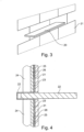
- Figure 2 is a cross-sectional view of the combination according to figure 1 , wherein the pre-wall is completed.
- Panels 7, such as plasterboard panels, have been arranged for this purpose over uprights 4.
- Shell 1 with flange 3 is then attached to plasterboard panels 7 and uprights 4.
- a sealing membrane 8 is then arranged over panels 7 and flange 3. This membrane 8 can optionally be attached to shell 1 in the factory.
- shell 1 can be made of for instance a plastic and sealing membrane 8 connects thereto, the whole pre-wall remains watertight despite the recessed part in the pre-wall.
- Figure 3 is a perspective view of a second embodiment of the combination according to the invention.
- An element 20 in the form of a shelf is placed here in a pre-wall covered with tiles 21.
- Figure 4 is a cross-sectional view of the combination according to figure 3 .
- Shelf 20 has been inserted into a shell 22, 23 with a recess 22 and a peripheral flange 23.
- This shell 22, 23 is arranged on a pre-wall of uprights 24 and wall panels 25.
- Pre-wall 24, 25 is covered with a watertight layer 26 which is adhered to flange 23 of shell 22, 23.
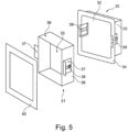
- FIG. 5 shows a third embodiment of the device according to the invention.
- This embodiment has a shell 30 and a nesting alcove-like element 31.
- Shell 30 is manufactured by deep-drawing of a plastic plate.
- a tray is hereby formed with a rear wall 32, side walls 33 and a peripheral flange 34.
- the nesting alcove-like element 31 is likewise tray-like, with a rear wall 35 and side walls 36.
- Two brackets 37 are provided on the side walls.
- Each bracket 37 has a slotted hole 38 whereby the bracket is displaceable relative to side walls 36.
- brackets 37 are accommodated as soon as element 31 is nested in shell 30.
- brackets 37 It is possible by adjusting the brackets 37 to determine how far element 31 can be pushed into shell 30.
- frame 40 provides for a neat finish of element 31 relative to the surrounding wall with finishing layer. Element 31 can protrude here through frame 40.
- Figure 6 shows an embodiment 50 of the device not according to the invention.
- a breeze block wall 51 is a recessed part in which a shell 52 with peripheral flange 53 is arranged.
- a 30 watertight membrane Arranged over peripheral flange 53 is a 30 watertight membrane, which is subsequently tiled with tiles 54.
- shell 52 arranged in shell 52 is a two-part alcove 55, 56, parts 55, 56 of which are telescopically slidable into each other.
- Part 55 has a U-shaped cross-section all around and forms an edge protruding from tile surface 54.
- shell 52 and part 56 can be provided a space in which functional elements can be accommodated, such as a reservoir for a soap dispenser.
- the soap dispenser can then for instance be accommodated in edge 55.
- a frame 57 which provides for a neat finish of tiles 54 relative to edge 55.
- FIG. 7 shows a fifth embodiment of combination 60 according to the invention.
- a lowered ceiling consisting of battens 62 and ceiling panels 63 is provided here under an intermediate floor 61.
- a shell 64 Arranged in ceiling panels 63 is a shell 64 which lies with the peripheral flange against the underside of ceiling plates 63.
- a loudspeaker 65 is provided in shell 64.
- a watertight or vapour-tight layer 66 which connects to the flanges of shell 64, whereby the lowered ceiling does not become any less watertight or vapour-tight despite the opening for shell 64 and loudspeaker 65.
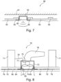
- FIG. 8 shows an embodiment of device 70 not according to the invention.
- Ceiling panels 72 are arranged here against a layer of beams 71.
- An opening in which a shell 73 is arranged is provided in ceiling panels 72.
- Shell 73 is provided with a fan 74, an outlet opening 75 to which an outlet tube 76 is connected, and a passage 77 for an electricity line 78.
- a watertight or vapour-tight layer 79 is here also arranged against ceiling panels 72 and the peripheral flange of shell 73.
- a finishing layer 80 such as a plaster layer, is provided over the watertight or vapour-tight layer 79.
- cover element 81 Placed in the access opening of shell 73 is a cover element 81 which is provided with a finishing element 82.
- Surface 83 of cover element 81, 82 lies flush here with surface 84 of finishing layer 80.
- Finishing element 82 takes a smaller form in this embodiment than the underlying cover element 81 so that between cover element 81 and finishing layer 80 a gap is formed along which air L can be drawn in by fan 74.
Description
- The invention relates to a combination according to claim 1, which is known from e.g.
DE 4309107 . - In sanitary spaces it is known to use breeze block walls or pre-walls so as to conceal different technical installations behind them, such as flushing cisterns, water conduits and electricity lines. The pre-wall is usually constructed from a metal frame which is covered with panels, particularly plasterboard panels. A watertight membrane is preferably then arranged over the plasterboard panels, after which a finishing layer such as a tile layer is arranged.
- Should a crack occur in the finishing layer the watertight layer prevents the underlying panels being damaged and the strength of the pre-wall being affected.
- When for instance a recessed part such as an alcove or a built-in cabinet is now arranged in the pre-wall, the watertight layer has to be interrupted because an opening is made in the pre-wall in which the alcove or built-in cabinet is arranged. In order to nevertheless keep the pre-wall watertight the alcove or built-in cabinet will have to be covered with a sealing layer, although this will have an adverse effect on the appearance of the alcove. Different parts will in addition have to be assembled from a membrane in order to form a watertight layer for the alcove.
- When a shelf is arranged on the pre-wall it will also be necessary for at least screws to be screwed into the pre-wall for the shelf supports, whereby the watertightness of the pre-wall is affected.
- It is further known to arrange electrical appliances, such as particularly a fan, in the ceiling or in walls. Moist air is hereby suctioned out of the space and discharged via an outlet pipe. If the fan and outlet pipe do not fit properly to the wall or ceiling, leakage can occur and moisture can penetrate behind the wall.
- It is an object of the invention to reduce or even obviate the above stated drawbacks.
- This object is achieved according to claim 1.
- The shell of the device can be arranged in a recessed part in a pre-wall. The flange of the shell overlaps with the pre-wall here and provides the option of fixing the shell to the pre-wall.
- When a watertight layer is then arranged on the pre-wall the layer can be arranged over the panels and overlapping with the flange of the shell. The edge of the watertight layer can be adhered here to the flange of the shell by means of for instance a glue or a mastic.
- After the watertight layer has been arranged, the pre-wall is finished with for instance a tile layer and, finally, the element can be nested in the shell of the device.
- Nesting is understood to mean that the element has substantially the same size as the shell, whereby the element can be placed in the shell and wherein for instance the walls of the element fit against the walls of the shell.
- It is thus possible with the combination according to the invention to place an element in a pre-wall without the watertightness of the pre-wall being affected. A watertight system is thus provided independently of the nesting element.
- In a preferred embodiment of the combination according to the invention the shell is manufactured from plastic. The shell is preferably deep-drawn.
- The advantage of plastic is that it is usually watertight. A plastic can moreover be easily deformed by heat and pressed into a desired shape, as takes place in deep-drawing.
- In a further preferred embodiment of the combination according to the invention the nesting element comprises an adjustable stop for adjusting the nesting depth of the element in the shell.
- The stop ensures that, after the shell has been arranged in the wall, it is possible to choose how far into the wall the nesting element is placed. The nesting part can thus protrude. For further finishing a frame can be arranged here around the protruding part of the nesting part. The frame can for instance conceal the adjustable stop from view.
- The frame can further be provided on the inner edge with a flexible edge. After watertight placing of the shell and tiling of the wall the frame with flexible edge can be arranged around the recessed part. The nesting element is then slid into the frame, wherein the flexible edge comes to lie against the outer wall of the nesting element and thus provides for a seal between the nesting element and the surrounding wall.
- In another preferred embodiment of the combination according to the invention the nesting element is alcove-like.
- Because the shell of the device provides for watertightness, the alcove-like element can be made from any desired material. The material used for the element can thus be optimally adapted to the aesthetic design.
- The shell can in addition be given a more functional form since it is concealed from view by the nesting element. It is thus possible for instance to make a connection for electrics in the shell which complies with the desired requirements of for instance watertightness. Lighting which connects to the electrical fitting in the shell can then be provided in the nesting element.
- Another option is to arrange an outflow in the shell which can for instance be used for ventilation or extraction. The nesting element here also conceals this outflow from view. A gap can then for instance be provided between the nesting element and the shell, whereby the outflow is connected to the space via the gap.
- The bottom (in use) of the alcove-like element is preferably inclining so that water which falls onto the bottom of the alcove-like element flows of its own accord out of the alcove. The adjustable stop can also be configured such that the alcove-like element can be tilted to some extent inside the shell, whereby the bottom likewise inclines.
- In another embodiment of the invention the nesting element is a shelf. The shell provides for a watertight gap in the wall into which the shelf can be inserted and herein protrudes partially from the wall, so that the shelf can be used to place objects thereon.
- In a highly preferred embodiment of the combination according to the invention the nesting element is an electrical appliance such as a loudspeaker.
- It is thus possible with the invention to incorporate an electrical appliance recessed into a wall or ceiling, wherein the watertightness of the wall or the ceiling is maintained.
- Preferably arranged in the shell is a cable bushing which is more preferably also watertight. Electric wires can for instance be carried therethrough into the shell in order to drive for instance a fan.
- Not according to the invention is when a discharge opening with which the air drawn in by the fan can be discharged can also be provided in the shell.
- The connection of an outlet tube can be made reliable and watertight by using the shell. In addition, a watertight connection of the shell to the surrounding wall is guaranteed, whereby undesired leakage cannot occur.
- The shell further provides the option of modifying the typically cylindrical shape of a fan so that at least the access opening of the shell has a different shape. For instance a rectangular or square shape. It is also possible to connect to the shell a frame along which air can be drawn in. The frame can for instance be an elongate profile, such as a tube, with an opening or openings extending in longitudinal direction.
- The combination according to the invention comprises a sealing membrane arranged on the flange. The advantage of arranging the sealing membrane on the flange is that this can already be done in the factory, whereby the reliability of the connection can be better monitored.
- In a further embodiment of the combination according to the invention the shell with the recess is formed from a sealing membrane. Through a suitable treatment sealing membrane can be provided with a recess, whereby it can also function as shell. The shell formed from membrane can be integrated here with the sealing membrane on the flange.
- In a preferred embodiment of the combination according to the invention the pre-wall is covered with a layer, for instance a tile layer, wherein the layer extends over the flange of the shell up to the edge of the recess.
- In a further preferred embodiment of the combination according to the invention the device comprises a cover element placed in the shell for the purpose of at least partially covering the access opening of the shell, wherein the surface of the cover element lies flush with the surface of the layer.
- The cover element preferably comprises adjusting means for adjusting the height of the surface of the cover element relative to the surface of the layer.
- An element placed in the shell is hidden from view using the cover element, while access can still be gained to the element by removing the cover element.
- It is thus possible for instance to arrange a fan in the shell and to partially cover this fan with a finishing layer such as a tile layer. The opening which is formed serves in the case of a fan as suction opening for the fan.
- A lamp or a loudspeaker for instance can on the other hand be provided as electrical element. The opening formed in the layer then serves to transmit the light or the sound.
- These and other features of the invention are further elucidated with reference to the accompanying drawings.
-
Figure 1 is a perspective view with cut-away parts of a first embodiment of the combination according to the invention. -
Figure 2 is a cross-sectional view of the combination according tofigure 1 . -
Figure 3 is a perspective view of a second embodiment of the combination according to the invention. -
Figure 4 is a cross-sectional view of the combination according tofigure 3 . -
Figure 5 shows a third embodiment of the device according to the invention. -
Figure 6 shows an embodiment of the device not according to the invention. -
Figure 7 shows a fifth embodiment of the combination according to the invention. -
Figure 8 shows an embodiment of the device not according to the invention. -
Figure 1 is a perspective view with cut-away parts of a first embodiment of the combination according to the invention. The device has a shell 1 with arecess 2 and aflange 3 arranged around the recess. This shell 1 is arranged between twouprights 4 of a pre-wall. - The device further has an
element 5 which in this embodiment takes the form of an alcove with adecorative edge 6. Thiselement 5 is placed in shell 1 following completion of the pre-wall. -
Figure 2 is a cross-sectional view of the combination according tofigure 1 , wherein the pre-wall is completed.Panels 7, such as plasterboard panels, have been arranged for this purpose overuprights 4. Shell 1 withflange 3 is then attached toplasterboard panels 7 anduprights 4. A sealingmembrane 8 is then arranged overpanels 7 andflange 3. Thismembrane 8 can optionally be attached to shell 1 in the factory. - A
finishing layer 9, such as a tile layer, is then arranged over sealingmembrane 8, andelement 5 is finally slid intorecess 2 of shell 1. - Because shell 1 can be made of for instance a plastic and sealing
membrane 8 connects thereto, the whole pre-wall remains watertight despite the recessed part in the pre-wall. -
Figure 3 is a perspective view of a second embodiment of the combination according to the invention. - An
element 20 in the form of a shelf is placed here in a pre-wall covered withtiles 21. -
Figure 4 is a cross-sectional view of the combination according tofigure 3 .Shelf 20 has been inserted into ashell recess 22 and aperipheral flange 23. Thisshell uprights 24 andwall panels 25. - Pre-wall 24, 25 is covered with a
watertight layer 26 which is adhered to flange 23 ofshell - With this embodiment it is possible to fix a
shelf 20 to a pre-wall 24, 25 without visible supports while maintaining the watertightness of the wall. -
Figure 5 shows a third embodiment of the device according to the invention. This embodiment has ashell 30 and a nesting alcove-like element 31.Shell 30 is manufactured by deep-drawing of a plastic plate. A tray is hereby formed with arear wall 32,side walls 33 and aperipheral flange 34. - The nesting alcove-
like element 31 is likewise tray-like, with arear wall 35 andside walls 36. Twobrackets 37 are provided on the side walls. Eachbracket 37 has a slottedhole 38 whereby the bracket is displaceable relative toside walls 36. - Provided in
side walls 33 inshell 30 are recessedportions 39 in whichbrackets 37 are accommodated as soon aselement 31 is nested inshell 30. - It is possible by adjusting the
brackets 37 to determine howfar element 31 can be pushed intoshell 30. - Finally,
frame 40 provides for a neat finish ofelement 31 relative to the surrounding wall with finishing layer.Element 31 can protrude here throughframe 40. -
Figure 6 shows anembodiment 50 of the device not according to the invention. Provided in abreeze block wall 51 is a recessed part in which ashell 52 withperipheral flange 53 is arranged. Arranged overperipheral flange 53 is a 30 watertight membrane, which is subsequently tiled withtiles 54. - Then arranged in
shell 52 is a two-part alcove parts Part 55 has a U-shaped cross-section all around and forms an edge protruding fromtile surface 54. - Between
shell 52 andpart 56 can be provided a space in which functional elements can be accommodated, such as a reservoir for a soap dispenser. The soap dispenser can then for instance be accommodated inedge 55. The advantage is thatalcove wall 51 being affected becauseshell 52 is arranged in the recessed part. - Further arranged around
edge 55 is a frame 57 which provides for a neat finish oftiles 54 relative to edge 55. -
Figure 7 shows a fifth embodiment ofcombination 60 according to the invention. A lowered ceiling consisting ofbattens 62 andceiling panels 63 is provided here under anintermediate floor 61. Arranged inceiling panels 63 is ashell 64 which lies with the peripheral flange against the underside ofceiling plates 63. Aloudspeaker 65 is provided inshell 64. Further provided againstceiling panels 63 is a watertight or vapour-tight layer 66 which connects to the flanges ofshell 64, whereby the lowered ceiling does not become any less watertight or vapour-tight despite the opening forshell 64 andloudspeaker 65. -
Figure 8 shows an embodiment ofdevice 70 not according to the invention.Ceiling panels 72 are arranged here against a layer ofbeams 71. An opening in which ashell 73 is arranged is provided inceiling panels 72.Shell 73 is provided with afan 74, anoutlet opening 75 to which anoutlet tube 76 is connected, and apassage 77 for anelectricity line 78. - A watertight or vapour-
tight layer 79 is here also arranged againstceiling panels 72 and the peripheral flange ofshell 73. Afinishing layer 80, such as a plaster layer, is provided over the watertight or vapour-tight layer 79. - Placed in the access opening of
shell 73 is acover element 81 which is provided with a finishingelement 82.Surface 83 ofcover element surface 84 of finishinglayer 80. - Finishing
element 82 takes a smaller form in this embodiment than theunderlying cover element 81 so that betweencover element 81 and finishing layer 80 a gap is formed along which air L can be drawn in byfan 74.
Claims (11)
- Combination of a pre-wall (7; 24, 25; 62, 63) comprising an opening and a device for installation in the opening in the pre-wall (7; 24, 25; 62, 63), the device comprising:- a shell (1; 22, 23; 30; 64;) with a recess (2; 22) arranged in the opening and a flat flange (3; 23; 34; 53) for watertight connection to the wall, wherein the flange lies against the edge of the opening, which flat flange is arranged around the recess (2; 22); and- an element (5; 20; 31; 55, 56) nesting in the recess (2; 22), wherein the element has substantially the same size as the shell, whereby the element can be placed in the shell and wherein for instance the walls of the element fit against the walls of the shell;characterized in that
a sealing membrane is arranged on the flat flange and in that the shell is watertight. - Combination as claimed in claim 1, wherein the shell (1; 22, 23; 30; 64) is manufactured from plastic.
- Combination as claimed in claim 2, wherein the shell (1; 22, 23; 30; 64) is deep-drawn.
- Combination as claimed in any of the foregoing claims, wherein the nesting element comprises an adjustable stop (37, 39) for adjusting the nesting depth of the element (31) in the shell (30).
- Combination as claimed in any of the foregoing claims, wherein the nesting element (31) is alcove-like.
- Combination as claimed in any of the claims 1-4, wherein the nesting element is a shelf (20).
- Combination as claimed in any of the claims 1-4, wherein the nesting element is an electrical appliance (65; 74) such as a loudspeaker.
- Combination as claimed in claim 1, wherein the shell with the recess is formed from a sealing membrane.
- Combination as claimed in claim 1, wherein the pre-wall is covered with a layer (9; 21), for instance a tile layer, wherein the layer (9; 21) extends over the flange (3; 23; 34) of the shell (1; 22, 23; 30; 64) up to the edge of the recess.
- Combination as claimed in claim 9, wherein the device comprises a cover element (40) placed in the shell for the purpose of at least partially covering the access opening of the shell, wherein the surface of the cover element (40) lies flush with the surface of the layer.
- Combination as claimed in claim 10, wherein the cover element (40) comprises adjusting means for adjusting the height of the surface of the cover element relative to the surface of the layer.
Priority Applications (2)
| Application Number | Priority Date | Filing Date | Title |
|---|---|---|---|
| EP16161946.5A EP3064656A1 (en) | 2014-01-20 | 2015-01-20 | Device for installation in a pre-wall |
| PL15151800.8T PL2896756T5 (en) | 2014-01-20 | 2015-01-20 | Device for installation in a prewall |
Applications Claiming Priority (1)
| Application Number | Priority Date | Filing Date | Title |
|---|---|---|---|
| NL2012114A NL2012114C2 (en) | 2014-01-20 | 2014-01-20 | DEVICE FOR BUILT-IN INTO A FRONT WALL. |
Related Child Applications (2)
| Application Number | Title | Priority Date | Filing Date |
|---|---|---|---|
| EP16161946.5A Division-Into EP3064656A1 (en) | 2014-01-20 | 2015-01-20 | Device for installation in a pre-wall |
| EP16161946.5A Division EP3064656A1 (en) | 2014-01-20 | 2015-01-20 | Device for installation in a pre-wall |
Publications (3)
| Publication Number | Publication Date |
|---|---|
| EP2896756A1 EP2896756A1 (en) | 2015-07-22 |
| EP2896756B1 EP2896756B1 (en) | 2018-11-28 |
| EP2896756B2 true EP2896756B2 (en) | 2023-08-02 |
Family
ID=50190688
Family Applications (2)
| Application Number | Title | Priority Date | Filing Date |
|---|---|---|---|
| EP16161946.5A Withdrawn EP3064656A1 (en) | 2014-01-20 | 2015-01-20 | Device for installation in a pre-wall |
| EP15151800.8A Active EP2896756B2 (en) | 2014-01-20 | 2015-01-20 | Device for installation in a prewall |
Family Applications Before (1)
| Application Number | Title | Priority Date | Filing Date |
|---|---|---|---|
| EP16161946.5A Withdrawn EP3064656A1 (en) | 2014-01-20 | 2015-01-20 | Device for installation in a pre-wall |
Country Status (4)
| Country | Link |
|---|---|
| EP (2) | EP3064656A1 (en) |
| ES (1) | ES2704457T5 (en) |
| NL (1) | NL2012114C2 (en) |
| PL (1) | PL2896756T5 (en) |
Families Citing this family (6)
| Publication number | Priority date | Publication date | Assignee | Title |
|---|---|---|---|---|
| NL2016847B1 (en) * | 2016-05-27 | 2017-12-04 | Easy Sanitary Solutions Bv | Built-in niche with door. |
| DE102016111340A1 (en) * | 2016-06-21 | 2017-12-21 | Stebler Holding Ag | Bracket and method for recessed mounting of a cabinet |
| EP3540136B1 (en) * | 2018-03-13 | 2020-11-25 | Geberit International AG | Wall-mounting device |
| EP3540135B1 (en) * | 2018-03-13 | 2021-02-24 | Geberit International AG | Use of an assembly set |
| ES2919076T3 (en) | 2018-06-27 | 2022-07-21 | Easy Sanitary Solutions Bv | Recess for mounting in an opening in a wall |
| EP3974588A1 (en) * | 2020-09-25 | 2022-03-30 | Rbm Ibox S.R.L. | Recessable box for housing hydraulic components |
Citations (3)
| Publication number | Priority date | Publication date | Assignee | Title |
|---|---|---|---|---|
| US20070101492A1 (en) † | 2003-02-05 | 2007-05-10 | Blankenship Gary M | Mold and process for forming a desired wall surface |
| DE102007040394A1 (en) † | 2006-08-30 | 2008-03-13 | Wedi, Stephan | Wall recess insert open to view comprises back and side walls produced from sandwich board consisting of core layer on which is mat forming back junction between corner cross-over area between back and side walls |
| US20100115865A1 (en) † | 2008-09-26 | 2010-05-13 | Steve Donnelly | Tile adaptor |
Family Cites Families (16)
| Publication number | Priority date | Publication date | Assignee | Title |
|---|---|---|---|---|
| US4794207A (en) | 1986-03-21 | 1988-12-27 | Enercept, Inc. | Electrical outlet unit for a building |
| US4757158A (en) | 1987-03-30 | 1988-07-12 | Lentz Stephen K | Air-vapor barrier box |
| NL8702483A (en) * | 1987-10-16 | 1989-05-16 | Johannes Wilhelmus Gerardus He | CABINET MODULE, IN PARTICULAR KITCHEN AND BATHROOM MODULE. |
| US5287665A (en) * | 1992-03-31 | 1994-02-22 | Rath Jr Robert | Waterproof flanged exterior wall outlet secured to a building framework |
| DE4241989A1 (en) | 1992-12-12 | 1994-06-16 | Grohe Armaturen Friedrich | Concealed mixer |
| DE4309107C2 (en) * | 1993-03-22 | 1995-01-05 | Mepa Pauli Und Menden Gmbh | Wall mounting arrangement for sanitary purposes |
| DE19648587B4 (en) | 1996-11-23 | 2004-04-15 | Hansa Metallwerke Ag | Flush-mounting box for sanitary fittings |
| WO2001073231A1 (en) | 2000-03-24 | 2001-10-04 | Unidrain A/S | A drain and a building structure having a drain |
| JP3972742B2 (en) * | 2002-06-24 | 2007-09-05 | 有限会社ミツオ電気 | How to install and seal ventilation fan hood |
| US20090223696A1 (en) | 2008-03-07 | 2009-09-10 | Gawoski Douglas S | Exterior semi-recessed electric junction box |
| US20100021294A1 (en) * | 2008-07-28 | 2010-01-28 | Yeh Tien-Bao | Fan structure for mounting in a light steel structure of a ceiling |
| DE102008059514A1 (en) | 2008-11-28 | 2010-06-02 | Dallmer Gmbh & Co. Kg | Drainage device for damp location, particularly for shower, comprises channel shaped drainage body with intake opening for sewage water, where drainage body comprises discharge opening for sewage water |
| DE202009006564U1 (en) | 2009-05-07 | 2012-02-27 | Hydrophon Kunststofftechnik Gmbh | Sealing system for floor drainage channels |
| ES2404561T3 (en) | 2009-12-07 | 2013-05-28 | Geberit International Ag | Sump for a sanitary installation and procedure for mounting such a sump |
| DK3138968T3 (en) | 2010-06-16 | 2019-11-11 | Tece Gmbh | Built-in cistern with moisture and leak protection |
| US20120279746A1 (en) | 2011-05-06 | 2012-11-08 | Brainwave Research Corporation | Vapor barrier mounting apparatus and method |
-
2014
- 2014-01-20 NL NL2012114A patent/NL2012114C2/en active
-
2015
- 2015-01-20 PL PL15151800.8T patent/PL2896756T5/en unknown
- 2015-01-20 ES ES15151800T patent/ES2704457T5/en active Active
- 2015-01-20 EP EP16161946.5A patent/EP3064656A1/en not_active Withdrawn
- 2015-01-20 EP EP15151800.8A patent/EP2896756B2/en active Active
Patent Citations (3)
| Publication number | Priority date | Publication date | Assignee | Title |
|---|---|---|---|---|
| US20070101492A1 (en) † | 2003-02-05 | 2007-05-10 | Blankenship Gary M | Mold and process for forming a desired wall surface |
| DE102007040394A1 (en) † | 2006-08-30 | 2008-03-13 | Wedi, Stephan | Wall recess insert open to view comprises back and side walls produced from sandwich board consisting of core layer on which is mat forming back junction between corner cross-over area between back and side walls |
| US20100115865A1 (en) † | 2008-09-26 | 2010-05-13 | Steve Donnelly | Tile adaptor |
Also Published As
| Publication number | Publication date |
|---|---|
| NL2012114C2 (en) | 2015-07-21 |
| EP2896756B1 (en) | 2018-11-28 |
| EP2896756A1 (en) | 2015-07-22 |
| PL2896756T5 (en) | 2023-11-27 |
| ES2704457T3 (en) | 2019-03-18 |
| ES2704457T5 (en) | 2024-03-04 |
| EP3064656A1 (en) | 2016-09-07 |
| PL2896756T3 (en) | 2019-04-30 |
Similar Documents
| Publication | Publication Date | Title |
|---|---|---|
| EP2896756B2 (en) | Device for installation in a prewall | |
| US10165905B2 (en) | Shower base | |
| US20120005967A1 (en) | Adaptor and method for facilitating the installation of walls around tubs, showers, and the like | |
| US7269862B2 (en) | Configurable shower system | |
| PT2009187E (en) | Sanitary facility with a floor drain and method for assembling such a sanitary facility | |
| EP3329057B1 (en) | Improvements in, or related to, drainage | |
| US20230200595A1 (en) | Wall Niche Kit and Related Methods | |
| US20130061388A1 (en) | Shower base for a space-limited room | |
| ES2826439T3 (en) | Shower drain and floor | |
| CA2680653A1 (en) | Tile adaptor | |
| JP6514590B6 (en) | Waterproof pan for washing machine | |
| EP2728078B1 (en) | Wall drain with height adjustable inflow opening | |
| US9523185B2 (en) | Plumbing fixture and accessory equipment concealing module | |
| KR101476336B1 (en) | Integral shelf with cabinet and washbasin | |
| JP5094617B2 (en) | Face-to-face kitchen | |
| JP2015137455A (en) | Installation structure for piping storage unit | |
| USD887021S1 (en) | Bathroom partition system | |
| EP4105395A1 (en) | Shower shelf, assembly and shower unit | |
| EP1564502B1 (en) | Wall sleeve for an air conditioning system | |
| EP3587682B1 (en) | Alcove for mounting in an opening in a wall | |
| JP2015188616A (en) | Bathroom unit and construction method thereof | |
| KR20170024831A (en) | Tube and wire guide device | |
| EP2365143A1 (en) | Suspended toilet bowl with bottom outlet | |
| WO2001012909A1 (en) | Building accessories | |
| JP2021078706A (en) | Faucet construction method and faucet fixing structure |
Legal Events
| Date | Code | Title | Description |
|---|---|---|---|
| PUAI | Public reference made under article 153(3) epc to a published international application that has entered the european phase |
Free format text: ORIGINAL CODE: 0009012 |
|
| 17P | Request for examination filed |
Effective date: 20150120 |
|
| AK | Designated contracting states |
Kind code of ref document: A1 Designated state(s): AL AT BE BG CH CY CZ DE DK EE ES FI FR GB GR HR HU IE IS IT LI LT LU LV MC MK MT NL NO PL PT RO RS SE SI SK SM TR |
|
| AX | Request for extension of the european patent |
Extension state: BA ME |
|
| 17P | Request for examination filed |
Effective date: 20160120 |
|
| RBV | Designated contracting states (corrected) |
Designated state(s): AL AT BE BG CH CY CZ DE DK EE ES FI FR GB GR HR HU IE IS IT LI LT LU LV MC MK MT NL NO PL PT RO RS SE SI SK SM TR |
|
| 17Q | First examination report despatched |
Effective date: 20160627 |
|
| RIN1 | Information on inventor provided before grant (corrected) |
Inventor name: KEIZERS, JURGEN HENDRIK PETER JOSEPH |
|
| GRAP | Despatch of communication of intention to grant a patent |
Free format text: ORIGINAL CODE: EPIDOSNIGR1 |
|
| STAA | Information on the status of an ep patent application or granted ep patent |
Free format text: STATUS: GRANT OF PATENT IS INTENDED |
|
| INTG | Intention to grant announced |
Effective date: 20180626 |
|
| GRAS | Grant fee paid |
Free format text: ORIGINAL CODE: EPIDOSNIGR3 |
|
| GRAA | (expected) grant |
Free format text: ORIGINAL CODE: 0009210 |
|
| STAA | Information on the status of an ep patent application or granted ep patent |
Free format text: STATUS: THE PATENT HAS BEEN GRANTED |
|
| AK | Designated contracting states |
Kind code of ref document: B1 Designated state(s): AL AT BE BG CH CY CZ DE DK EE ES FI FR GB GR HR HU IE IS IT LI LT LU LV MC MK MT NL NO PL PT RO RS SE SI SK SM TR |
|
| REG | Reference to a national code |
Ref country code: CH Ref legal event code: EP |
|
| REG | Reference to a national code |
Ref country code: CH Ref legal event code: NV Representative=s name: VALIPAT S.A. GEVERS SA, CH |
|
| REG | Reference to a national code |
Ref country code: AT Ref legal event code: REF Ref document number: 1070396 Country of ref document: AT Kind code of ref document: T Effective date: 20181215 |
|
| REG | Reference to a national code |
Ref country code: DE Ref legal event code: R096 Ref document number: 602015020233 Country of ref document: DE |
|
| REG | Reference to a national code |
Ref country code: IE Ref legal event code: FG4D |
|
| REG | Reference to a national code |
Ref country code: NL Ref legal event code: FP |
|
| REG | Reference to a national code |
Ref country code: ES Ref legal event code: FG2A Ref document number: 2704457 Country of ref document: ES Kind code of ref document: T3 Effective date: 20190318 |
|
| REG | Reference to a national code |
Ref country code: CH Ref legal event code: PCAR Free format text: NEW ADDRESS: RUE DES NOYERS 11, 2000 NEUCHATEL (CH) |
|
| REG | Reference to a national code |
Ref country code: LT Ref legal event code: MG4D |
|
| REG | Reference to a national code |
Ref country code: AT Ref legal event code: MK05 Ref document number: 1070396 Country of ref document: AT Kind code of ref document: T Effective date: 20181128 |
|
| PG25 | Lapsed in a contracting state [announced via postgrant information from national office to epo] |
Ref country code: LT Free format text: LAPSE BECAUSE OF FAILURE TO SUBMIT A TRANSLATION OF THE DESCRIPTION OR TO PAY THE FEE WITHIN THE PRESCRIBED TIME-LIMIT Effective date: 20181128 Ref country code: IS Free format text: LAPSE BECAUSE OF FAILURE TO SUBMIT A TRANSLATION OF THE DESCRIPTION OR TO PAY THE FEE WITHIN THE PRESCRIBED TIME-LIMIT Effective date: 20190328 Ref country code: BG Free format text: LAPSE BECAUSE OF FAILURE TO SUBMIT A TRANSLATION OF THE DESCRIPTION OR TO PAY THE FEE WITHIN THE PRESCRIBED TIME-LIMIT Effective date: 20190228 Ref country code: NO Free format text: LAPSE BECAUSE OF FAILURE TO SUBMIT A TRANSLATION OF THE DESCRIPTION OR TO PAY THE FEE WITHIN THE PRESCRIBED TIME-LIMIT Effective date: 20190228 Ref country code: HR Free format text: LAPSE BECAUSE OF FAILURE TO SUBMIT A TRANSLATION OF THE DESCRIPTION OR TO PAY THE FEE WITHIN THE PRESCRIBED TIME-LIMIT Effective date: 20181128 Ref country code: AT Free format text: LAPSE BECAUSE OF FAILURE TO SUBMIT A TRANSLATION OF THE DESCRIPTION OR TO PAY THE FEE WITHIN THE PRESCRIBED TIME-LIMIT Effective date: 20181128 Ref country code: LV Free format text: LAPSE BECAUSE OF FAILURE TO SUBMIT A TRANSLATION OF THE DESCRIPTION OR TO PAY THE FEE WITHIN THE PRESCRIBED TIME-LIMIT Effective date: 20181128 Ref country code: FI Free format text: LAPSE BECAUSE OF FAILURE TO SUBMIT A TRANSLATION OF THE DESCRIPTION OR TO PAY THE FEE WITHIN THE PRESCRIBED TIME-LIMIT Effective date: 20181128 |
|
| PG25 | Lapsed in a contracting state [announced via postgrant information from national office to epo] |
Ref country code: RS Free format text: LAPSE BECAUSE OF FAILURE TO SUBMIT A TRANSLATION OF THE DESCRIPTION OR TO PAY THE FEE WITHIN THE PRESCRIBED TIME-LIMIT Effective date: 20181128 Ref country code: SE Free format text: LAPSE BECAUSE OF FAILURE TO SUBMIT A TRANSLATION OF THE DESCRIPTION OR TO PAY THE FEE WITHIN THE PRESCRIBED TIME-LIMIT Effective date: 20181128 Ref country code: AL Free format text: LAPSE BECAUSE OF FAILURE TO SUBMIT A TRANSLATION OF THE DESCRIPTION OR TO PAY THE FEE WITHIN THE PRESCRIBED TIME-LIMIT Effective date: 20181128 Ref country code: GR Free format text: LAPSE BECAUSE OF FAILURE TO SUBMIT A TRANSLATION OF THE DESCRIPTION OR TO PAY THE FEE WITHIN THE PRESCRIBED TIME-LIMIT Effective date: 20190301 Ref country code: PT Free format text: LAPSE BECAUSE OF FAILURE TO SUBMIT A TRANSLATION OF THE DESCRIPTION OR TO PAY THE FEE WITHIN THE PRESCRIBED TIME-LIMIT Effective date: 20190328 |
|
| PG25 | Lapsed in a contracting state [announced via postgrant information from national office to epo] |
Ref country code: DK Free format text: LAPSE BECAUSE OF FAILURE TO SUBMIT A TRANSLATION OF THE DESCRIPTION OR TO PAY THE FEE WITHIN THE PRESCRIBED TIME-LIMIT Effective date: 20181128 Ref country code: CZ Free format text: LAPSE BECAUSE OF FAILURE TO SUBMIT A TRANSLATION OF THE DESCRIPTION OR TO PAY THE FEE WITHIN THE PRESCRIBED TIME-LIMIT Effective date: 20181128 |
|
| REG | Reference to a national code |
Ref country code: DE Ref legal event code: R026 Ref document number: 602015020233 Country of ref document: DE |
|
| PG25 | Lapsed in a contracting state [announced via postgrant information from national office to epo] |
Ref country code: SK Free format text: LAPSE BECAUSE OF FAILURE TO SUBMIT A TRANSLATION OF THE DESCRIPTION OR TO PAY THE FEE WITHIN THE PRESCRIBED TIME-LIMIT Effective date: 20181128 Ref country code: RO Free format text: LAPSE BECAUSE OF FAILURE TO SUBMIT A TRANSLATION OF THE DESCRIPTION OR TO PAY THE FEE WITHIN THE PRESCRIBED TIME-LIMIT Effective date: 20181128 Ref country code: MC Free format text: LAPSE BECAUSE OF FAILURE TO SUBMIT A TRANSLATION OF THE DESCRIPTION OR TO PAY THE FEE WITHIN THE PRESCRIBED TIME-LIMIT Effective date: 20181128 Ref country code: EE Free format text: LAPSE BECAUSE OF FAILURE TO SUBMIT A TRANSLATION OF THE DESCRIPTION OR TO PAY THE FEE WITHIN THE PRESCRIBED TIME-LIMIT Effective date: 20181128 Ref country code: SM Free format text: LAPSE BECAUSE OF FAILURE TO SUBMIT A TRANSLATION OF THE DESCRIPTION OR TO PAY THE FEE WITHIN THE PRESCRIBED TIME-LIMIT Effective date: 20181128 |
|
| PLBI | Opposition filed |
Free format text: ORIGINAL CODE: 0009260 |
|
| PG25 | Lapsed in a contracting state [announced via postgrant information from national office to epo] |
Ref country code: LU Free format text: LAPSE BECAUSE OF NON-PAYMENT OF DUE FEES Effective date: 20190120 |
|
| 26 | Opposition filed |
Opponent name: GEBERIT INTERNATIONAL AG Effective date: 20190827 |
|
| REG | Reference to a national code |
Ref country code: IE Ref legal event code: MM4A |
|
| PG25 | Lapsed in a contracting state [announced via postgrant information from national office to epo] |
Ref country code: SI Free format text: LAPSE BECAUSE OF FAILURE TO SUBMIT A TRANSLATION OF THE DESCRIPTION OR TO PAY THE FEE WITHIN THE PRESCRIBED TIME-LIMIT Effective date: 20181128 |
|
| PLAX | Notice of opposition and request to file observation + time limit sent |
Free format text: ORIGINAL CODE: EPIDOSNOBS2 |
|
| PG25 | Lapsed in a contracting state [announced via postgrant information from national office to epo] |
Ref country code: IE Free format text: LAPSE BECAUSE OF NON-PAYMENT OF DUE FEES Effective date: 20190120 |
|
| PLBB | Reply of patent proprietor to notice(s) of opposition received |
Free format text: ORIGINAL CODE: EPIDOSNOBS3 |
|
| PG25 | Lapsed in a contracting state [announced via postgrant information from national office to epo] |
Ref country code: TR Free format text: LAPSE BECAUSE OF FAILURE TO SUBMIT A TRANSLATION OF THE DESCRIPTION OR TO PAY THE FEE WITHIN THE PRESCRIBED TIME-LIMIT Effective date: 20181128 |
|
| PG25 | Lapsed in a contracting state [announced via postgrant information from national office to epo] |
Ref country code: MT Free format text: LAPSE BECAUSE OF NON-PAYMENT OF DUE FEES Effective date: 20190120 |
|
| REG | Reference to a national code |
Ref country code: CH Ref legal event code: PK Free format text: TITEL |
|
| PG25 | Lapsed in a contracting state [announced via postgrant information from national office to epo] |
Ref country code: CY Free format text: LAPSE BECAUSE OF FAILURE TO SUBMIT A TRANSLATION OF THE DESCRIPTION OR TO PAY THE FEE WITHIN THE PRESCRIBED TIME-LIMIT Effective date: 20181128 |
|
| APBM | Appeal reference recorded |
Free format text: ORIGINAL CODE: EPIDOSNREFNO |
|
| APBP | Date of receipt of notice of appeal recorded |
Free format text: ORIGINAL CODE: EPIDOSNNOA2O |
|
| APAH | Appeal reference modified |
Free format text: ORIGINAL CODE: EPIDOSCREFNO |
|
| PG25 | Lapsed in a contracting state [announced via postgrant information from national office to epo] |
Ref country code: HU Free format text: LAPSE BECAUSE OF FAILURE TO SUBMIT A TRANSLATION OF THE DESCRIPTION OR TO PAY THE FEE WITHIN THE PRESCRIBED TIME-LIMIT; INVALID AB INITIO Effective date: 20150120 |
|
| APBM | Appeal reference recorded |
Free format text: ORIGINAL CODE: EPIDOSNREFNO |
|
| APBP | Date of receipt of notice of appeal recorded |
Free format text: ORIGINAL CODE: EPIDOSNNOA2O |
|
| APBQ | Date of receipt of statement of grounds of appeal recorded |
Free format text: ORIGINAL CODE: EPIDOSNNOA3O |
|
| APBQ | Date of receipt of statement of grounds of appeal recorded |
Free format text: ORIGINAL CODE: EPIDOSNNOA3O |
|
| PG25 | Lapsed in a contracting state [announced via postgrant information from national office to epo] |
Ref country code: MK Free format text: LAPSE BECAUSE OF FAILURE TO SUBMIT A TRANSLATION OF THE DESCRIPTION OR TO PAY THE FEE WITHIN THE PRESCRIBED TIME-LIMIT Effective date: 20181128 |
|
| APBU | Appeal procedure closed |
Free format text: ORIGINAL CODE: EPIDOSNNOA9O |
|
| PGFP | Annual fee paid to national office [announced via postgrant information from national office to epo] |
Ref country code: FR Payment date: 20230113 Year of fee payment: 9 Ref country code: ES Payment date: 20230222 Year of fee payment: 9 Ref country code: CH Payment date: 20230120 Year of fee payment: 9 |
|
| PGFP | Annual fee paid to national office [announced via postgrant information from national office to epo] |
Ref country code: PL Payment date: 20230109 Year of fee payment: 9 Ref country code: IT Payment date: 20230119 Year of fee payment: 9 Ref country code: GB Payment date: 20230118 Year of fee payment: 9 Ref country code: DE Payment date: 20230119 Year of fee payment: 9 Ref country code: BE Payment date: 20230113 Year of fee payment: 9 |
|
| PGFP | Annual fee paid to national office [announced via postgrant information from national office to epo] |
Ref country code: NL Payment date: 20230117 Year of fee payment: 9 |
|
| PUAH | Patent maintained in amended form |
Free format text: ORIGINAL CODE: 0009272 |
|
| STAA | Information on the status of an ep patent application or granted ep patent |
Free format text: STATUS: PATENT MAINTAINED AS AMENDED |
|
| 27A | Patent maintained in amended form |
Effective date: 20230802 |
|
| AK | Designated contracting states |
Kind code of ref document: B2 Designated state(s): AL AT BE BG CH CY CZ DE DK EE ES FI FR GB GR HR HU IE IS IT LI LT LU LV MC MK MT NL NO PL PT RO RS SE SI SK SM TR |
|
| REG | Reference to a national code |
Ref country code: DE Ref legal event code: R102 Ref document number: 602015020233 Country of ref document: DE |
|
| P01 | Opt-out of the competence of the unified patent court (upc) registered |
Effective date: 20230831 |
|
| REG | Reference to a national code |
Ref country code: NL Ref legal event code: FP |
|
| PGFP | Annual fee paid to national office [announced via postgrant information from national office to epo] |
Ref country code: PL Payment date: 20231228 Year of fee payment: 10 Ref country code: NL Payment date: 20240125 Year of fee payment: 10 |
|
| REG | Reference to a national code |
Ref country code: ES Ref legal event code: DC2A Ref document number: 2704457 Country of ref document: ES Kind code of ref document: T5 Effective date: 20240304 |
|
| PGFP | Annual fee paid to national office [announced via postgrant information from national office to epo] |
Ref country code: ES Payment date: 20240209 Year of fee payment: 10 |