EP2896075B1 - Dispositif et procede de restauration de cellules solaires photo voltaiques a base de silicium - Google Patents
Dispositif et procede de restauration de cellules solaires photo voltaiques a base de silicium Download PDFInfo
- Publication number
- EP2896075B1 EP2896075B1 EP13774464.5A EP13774464A EP2896075B1 EP 2896075 B1 EP2896075 B1 EP 2896075B1 EP 13774464 A EP13774464 A EP 13774464A EP 2896075 B1 EP2896075 B1 EP 2896075B1
- Authority
- EP
- European Patent Office
- Prior art keywords
- photovoltaic solar
- solar cell
- liquid
- temperature
- tank
- Prior art date
- Legal status (The legal status is an assumption and is not a legal conclusion. Google has not performed a legal analysis and makes no representation as to the accuracy of the status listed.)
- Not-in-force
Links
Images

Classifications
-
- H—ELECTRICITY
- H10—SEMICONDUCTOR DEVICES; ELECTRIC SOLID-STATE DEVICES NOT OTHERWISE PROVIDED FOR
- H10F—INORGANIC SEMICONDUCTOR DEVICES SENSITIVE TO INFRARED RADIATION, LIGHT, ELECTROMAGNETIC RADIATION OF SHORTER WAVELENGTH OR CORPUSCULAR RADIATION
- H10F10/00—Individual photovoltaic cells, e.g. solar cells
-
- H—ELECTRICITY
- H10—SEMICONDUCTOR DEVICES; ELECTRIC SOLID-STATE DEVICES NOT OTHERWISE PROVIDED FOR
- H10F—INORGANIC SEMICONDUCTOR DEVICES SENSITIVE TO INFRARED RADIATION, LIGHT, ELECTROMAGNETIC RADIATION OF SHORTER WAVELENGTH OR CORPUSCULAR RADIATION
- H10F71/00—Manufacture or treatment of devices covered by this subclass
- H10F71/121—The active layers comprising only Group IV materials
-
- H—ELECTRICITY
- H10—SEMICONDUCTOR DEVICES; ELECTRIC SOLID-STATE DEVICES NOT OTHERWISE PROVIDED FOR
- H10F—INORGANIC SEMICONDUCTOR DEVICES SENSITIVE TO INFRARED RADIATION, LIGHT, ELECTROMAGNETIC RADIATION OF SHORTER WAVELENGTH OR CORPUSCULAR RADIATION
- H10F71/00—Manufacture or treatment of devices covered by this subclass
- H10F71/128—Annealing
-
- Y—GENERAL TAGGING OF NEW TECHNOLOGICAL DEVELOPMENTS; GENERAL TAGGING OF CROSS-SECTIONAL TECHNOLOGIES SPANNING OVER SEVERAL SECTIONS OF THE IPC; TECHNICAL SUBJECTS COVERED BY FORMER USPC CROSS-REFERENCE ART COLLECTIONS [XRACs] AND DIGESTS
- Y02—TECHNOLOGIES OR APPLICATIONS FOR MITIGATION OR ADAPTATION AGAINST CLIMATE CHANGE
- Y02E—REDUCTION OF GREENHOUSE GAS [GHG] EMISSIONS, RELATED TO ENERGY GENERATION, TRANSMISSION OR DISTRIBUTION
- Y02E10/00—Energy generation through renewable energy sources
- Y02E10/50—Photovoltaic [PV] energy
- Y02E10/547—Monocrystalline silicon PV cells
-
- Y—GENERAL TAGGING OF NEW TECHNOLOGICAL DEVELOPMENTS; GENERAL TAGGING OF CROSS-SECTIONAL TECHNOLOGIES SPANNING OVER SEVERAL SECTIONS OF THE IPC; TECHNICAL SUBJECTS COVERED BY FORMER USPC CROSS-REFERENCE ART COLLECTIONS [XRACs] AND DIGESTS
- Y02—TECHNOLOGIES OR APPLICATIONS FOR MITIGATION OR ADAPTATION AGAINST CLIMATE CHANGE
- Y02P—CLIMATE CHANGE MITIGATION TECHNOLOGIES IN THE PRODUCTION OR PROCESSING OF GOODS
- Y02P70/00—Climate change mitigation technologies in the production process for final industrial or consumer products
- Y02P70/50—Manufacturing or production processes characterised by the final manufactured product
Definitions
- the invention relates to a device and a method for suppressing the effects of degradation of the efficiency under illumination of silicon-based photovoltaic solar cells.
- Photovoltaic solar cells made from amorphous (a-Si), monocrystalline (sc-Si) or multicrystalline (mc-Si) silicon substrates may suffer from a performance degradation effect under illumination. This phenomenon occurs during the first uses of photovoltaic solar cells, and is usually called “LID" (Light-Induced-Degradation). The physical mechanisms at the origin of this deterioration of the efficiency of photovoltaic solar cells under illumination remain poorly known. In addition, some scientific studies have shown that light elements present in silicon, especially hydrogen (H), boron (B) and oxygen (O) atoms, generally participate in the formation and activation of defects in the illumination of photovoltaic solar cells.
- H hydrogen
- B boron
- O oxygen
- the "LID" effects can be suppressed by injecting charge carriers into the photovoltaic solar cells while heating said cells.
- International demand WO 2007/107351 discloses a method for stabilizing the efficiency of photovoltaic solar cells during illumination.
- the method for restoring the cells comprises a step of injecting charge carriers via a illumination or a direct polarization of the photovoltaic solar cell, and a step of heating the substrate at a temperature between 50 ° C and 230 ° C.
- This restoration process has allowed the photovoltaic solar cell treated, to find stable performance under normal operating conditions.
- this type of restoration process requires precise control of the temperature.
- the restoration effects only take place if the temperature of the solar photovoltaic cells does not exceed a certain limit temperature which is typically of the order of 200 ° C or even lower temperature. Indeed, the performance of some silicon-based photovoltaic solar cells can be affected when they are maintained at temperatures above 150 ° C.
- treatment time is meant the time during which the solar cells are maintained at a certain temperature during the generation of charge carriers in the cells.
- the treatment times can reach a hundred hours, which makes this process incompatible with conventional industrial processes for manufacturing photovoltaic solar cells.
- the kinetics of restoration of the photovoltaic cells can be accelerated by increasing the amount of charge carriers injected into the solar photovoltaic cell treated. This increase can be achieved in particular by increasing, the power of the incident illumination or the intensity of the electric current injected into the cell. However, increasing the incident light power or the electric current injected, causes a very significant increase in the temperature of the photovoltaic solar cell, limiting or eliminating the restoration effects of the photovoltaic solar cell.
- the utility model application CN201450015 discloses a device for heating and illuminating silicon-based solar cells to restore them.
- the device includes a fan system for cooling the photovoltaic cells during processing.
- a fan-based system does not make it possible to obtain good quality solar cells.
- this type of device can cause mechanical stress problems, thus creating microcracks in photovoltaic solar cells.
- a device for restoring at least one silicon-based photovoltaic solar cell comprising a support for the photovoltaic solar cell, and means for generating charge carriers in the photovoltaic solar cell.
- the device comprises a tank intended to be filled with a liquid, and the support is configured to dispose the photovoltaic solar cell in the liquid.
- the method comprises a step where the photovoltaic solar cell is immersed in a liquid during the generation of charge carriers in the photovoltaic solar cell, so as to regulate the temperature of the photovoltaic solar cell at a temperature value or in a range of target temperature in the temperature range 50 ° C - 230 ° C.
- the silicon photovoltaic solar cell healing device described below differs from the prior art in particular in that it provides elements for regulating the temperature of photovoltaic solar cells during the implementation of the restoration process. to increase the kinetics of restoration of the treated cells.
- a device for restoring silicon-based photovoltaic cells comprises a support 1 of at least one photovoltaic solar cell 2.
- the restoration device also comprises means 3 for generating charge carriers in the photovoltaic solar cell 2, and preferentially a heat source (not shown) configured to heat the photovoltaic solar cell 2.
- the generation means 3 of charge carriers may, for example, comprise a light source illuminating the photovoltaic solar cell 2 and / or means for injecting an electric current into the solar photovoltaic cell 2.
- the charge carrier generation means 3 are represented as being a light source 3b, illuminating the photovoltaic solar cell 2 by a light beam 3f.
- the generation means 3 of charge carriers can also constitute the heat source of the restoration device.
- halogen lamps can constitute both the means of generating charge carriers and the source of heat.
- the restoration device makes it possible to heat the photovoltaic solar cell 2 while injecting charge carriers therein, in order to restore said cell to effects of degradation of the efficiency under illumination.
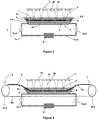
- the device comprises a tank 4 intended to be filled with a liquid 5.
- the support 1 is configured to arrange the photovoltaic solar cell 2 in the liquid 5. This is, in particular, completely immersed in the liquid 5.
- the tank 4 comprises a bottom 4-f and side walls.
- the side walls comprise a first side wall 4-1 disposed at a first end of the tank 4, and a second side wall 4-2 disposed. at a second end opposite the first end along a longitudinal axis 4-a of scrolling solar cells 2.
- the recovery device provided with the tank 4 advantageously allows efficient and homogeneous dissipation of the temperature of the photovoltaic solar cell 2 during the injection of charge carriers, including during a strong injection of charge carriers.
- a strong injection of charge carriers allows an acceleration of the kinetics of restoration, and thus a reduction in the processing time of the photovoltaic cells.
- the liquid 5 submerging the photovoltaic solar cell 2 the rise in temperature, generated by the amount of charge carrier injected, is effectively dissipated, which allows to obtain a temperature regulation of the photovoltaic solar cell, while avoiding thermomechanical stress problems.
- the healing device allows the realization of a fast and efficient restoration of silicon-based photovoltaic cells, while preserving the mechanical integrity of said cells.
- the restoration device preferably comprises a heat source configured to heat the photovoltaic solar cell.
- the heat source can be optional: the solar photovoltaic cell could be heated directly by the liquid 5.
- the tank 4 of the recovery device comprises a regulator 6 of the liquid temperature 5.
- the regulator 6 can comprise thermoelectric devices or electric heating resistors, arranged in the walls of the tank 4, and controlled by a control circuit not shown on the figure 2 .
- the regulator 6 makes it possible to precisely control the temperature of the liquid 5 in the tank 4, and thus the temperature of the photovoltaic solar cell 2. As a result, the regulator 6 makes it possible to regulate the temperature of the photovoltaic solar cell 2 to a value or a target temperature range, when injecting charge carriers.
- the regulator 6 of the temperature of the liquid 5 is configured to regulate the temperature of the photovoltaic solar cell 2 to a particular temperature value (for example at 170 ° C.) or in a particular temperature range (for example between 120 ° C. C and 190 ° C). Whether the regulation concerns a given temperature value or a temperature range, the target value or temperature range still remains in the temperature range 50 ° C - 230 ° C.
- the restoration effects can only be realized if the temperature of the cell is in this temperature range.
- the range of temperatures 50 ° C - 230 ° C thus makes it possible to obtain a fast and efficient restoration of the photovoltaic cells 2, effects of degradation of the efficiency under illumination, while preserving the photovoltaic performances of the treated cells.
- thermocouples can be placed along the entire length of the device in order to precisely control the temperature of the liquid 5 and / or the photovoltaic solar cells 2.
- the tank 4 comprises a circulation device 7 of the liquid 5 in the tank 4.
- the circulation means 7 of the liquid 5 comprises first 7c-1 and second 7c-2 conduits connected to each other. other, at one of their extremities.
- the first duct 7c-1 can be connected to the tank 4 via an orifice formed in the first side wall 4-1.
- the second duct is connected to the tank 4 via an orifice formed, preferably, in the second lateral wall 4-2.
- the first duct 7c-1 may comprise, for example, a first pump 7p-1 configured to suck the liquid 5 from the tank 4 to the second duct 7c-2, which comprises a second pump 7p-2.
- the second pump 7p-2 is configured to inject the liquid 5 into the tank 4. This configuration of the first 7c-1 and second 7c-2 ducts allows a circulation of the liquid 5 in the tank 4 along the longitudinal axis 4-a.
- a circulation of the liquid 5 in the tank 4 advantageously allows a better homogenization of the temperature of the liquid 5 in the tank 4, which allows a better dissipation of the heat of the photovoltaic solar cell 2 towards the liquid 5.
- the circulation means 7 are connected to the temperature regulator 6 of the liquid 5.
- the temperature regulator 6 is configured to control the temperature of the liquid injected into the tank 4 via the second conduit 7c -2.
- the control circuit of the temperature controller 6 also controls the first 7p-1 and second 7p-2 pumps.
- the control circuit is configured to define the temperature of the solar photovoltaic cell 2 or a temperature range allowed for the solar cell.
- the tank 4 may comprise a mechanical stirring circuit 8 of the liquid 5 in the tank 4.
- this mixing circuit 8 is associated with the liquid circulation means 5 in the tank 4.
- the mechanical means 8 may comprise at least one propeller disposed in the tank 4, for example on one of the side walls.
- the tank 4 may also include an ultrasound transducer.
- the ultrasound transducer is disposed in the tank so as to be as close as possible to the photovoltaic solar cell 2 to be treated. In order not to disturb the propagation of the ultrasonic waves towards the photovoltaic solar cell 2, the transducer is preferentially arranged so as to avoid any solid obstacle, such as the support 1, between the ultrasound transducer and said cell.
- the ultrasound transducer advantageously allows a generation of a convection movement in the liquid 5, thus leading to a stirring of the liquid and a homogenization of its temperature.
- the transducer generates ultrasonic waves that can promote the effects of diffusion, reorientation and dissociation of defects and impurity complexes, thus further accelerating the kinetics of restoration.
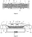
- the restoration device comprises displacement means 9 of the support 1 in the tank 4.
- the displacement means 9 are configured to move the photovoltaic solar cell 2 in a direction parallel to the surface of the liquid 5 in the tank 4.
- the support 1 is shaped so as to ensure a stable holding of solar photovoltaic cells 2 on its surface.
- the moving means 9 of the support 1 may be of conveyor belt type.
- the displacement means 9 may comprise first 9r-1 and second 9r-2 main rollers, around which the support 1 is wound to form a closed loop 9b.
- the displacement means 9 comprise secondary rollers 9s configured to modify the axis of translation of the support 1 during its displacement along the path of the closed loop 9b.
- the secondary rollers 9s are in contact only with the edges of the support 1. This arrangement makes it possible to avoid any contact between the secondary rollers 9s and the photovoltaic solar cells 2 during the displacement of the support 1.
- at least one of the two main rollers 9r-1 and 9r-2 is a driving roll, configured to move the support 1 along the path of the closed loop 9b.
- This configuration of the restoration device thus allows an accelerated restoration of several photovoltaic cells arranged, for example the one after another or side by side, on the support 1 rolling.
- the restoration device can thus easily integrate a large-scale production line.
- the first main roll 9r-1 is a free roll
- the second main roll 9r-2 is a motor roll.
- the drive roll is configured to obtain a direction of movement of the support 1, opposite to the direction of displacement of the liquid 5 in the tank 4. These opposite displacements of the support 1 and the liquid 5, then allow a better dissipation of the heat from the photovoltaic solar cells 2 to the liquid 5 and promote the mixing of the liquid 5.
- the support 1 has through holes 10 so that the liquid 5 is in contact with the face of the photovoltaic solar cell 2 disposed on the support 1.
- This configuration of the support 1 makes it possible to increase the contact surface between the photovoltaic solar cells 2 and the liquid 5, when they are embedded in the tank 4. Therefore, the increase of the contact surface between the liquid 5 and photovoltaic solar cells advantageously allows to ensure better heat exchange between the cells 2 and the liquid 5.
- the support 1 it is also advantageous for the support 1 to be based on a material having a thermal conductivity ⁇ s greater than the thermal conductivity of the photovoltaic solar cell ⁇ c .
- the support 1 consists of flexible meshes of stainless steel.
- the general control circuit is configured to regulate the temperature of the photovoltaic solar cell 2 to a stable value or temperature range, in the temperature range 50 ° C - 230 ° C, and preferably 120 ° C - 210 ° C.
- the general control circuit also controls the speed of movement of the support 1 in the tank 4, and the stirring means.
- the charge carrier generating means 3 comprise a light source 3b intended to illuminate the photovoltaic solar cell 2.
- the light source 3b may comprise monochromatic lamps making it possible to produce an incident light beam having a wavelength of between 300 and 1300 nm.
- the light source 3b can also include halogen or xenon lamps to produce a white light.
- the light source 3b is configured to provide intense illumination so that the photovoltaic cells receive an illumination greater than 0.05 W.cm -2 .
- the light source 3b may comprise a laser source, which advantageously generates an intense illumination. The use of a laser source advantageously allows a reduction in energy consumption, compared with other light sources.
- the light source 3b comprises an optical system 3b 'disposed between the photovoltaic solar cells and the light source 3b.
- the light source 3b is a laser source
- a diverging lens thus makes it possible to increase the area of the photovoltaic solar cell receiving the illumination.
- the source As a halogen lamp or a monochromatic lamp, it is advantageous to use a convergent lens as an optical system to concentrate the light beam and to increase the intensity of the illumination received by the photovoltaic solar cell 2.
- the charge carrier generating means 3 may comprise means for injecting an electric current into the photovoltaic solar cell 2.
- the restoration device comprises spikes, connected to a potential difference source.
- the tips are configured to contact the photovoltaic solar cell 2 to inject an electric current therein.
- the means for injecting an electric current may comprise means for moving the tips, configured so that the tips and the support 1 have the same movement.
- the tips can be considered as fixed elements relative to the photovoltaic solar cell 2 in displacement.
- the method uses one of the restoration devices described above, and illustrated in FIGS. Figures 1 to 6 .
- the restoration method comprises a step where at least one photovoltaic solar cell 2 is provided made in a substrate or in an active layer based on silicon (amorphous, monocrystalline or multicrystalline).
- the restoration process is carried out by immersing the photovoltaic solar cell 2 in a liquid 5 during the generation of charge carriers in said cell 2, so as to regulate the temperature of the photovoltaic solar cell 2 to a value or a temperature range target, in the temperature range 50 ° C - 230 ° C and preferably 120 ° C - 210 ° C.
- the heating of the photovoltaic solar cell 2 can be carried out by a heat source or by the means 3 for generating charge carriers, for example by halogen lamps.
- the restoration device comprising the regulator of the temperature 6 of the liquid 5 is used.
- the liquid 5 can be either transparent to the emitted light beam, or electrically insulating.
- the charge carriers are injected into the photovoltaic solar cell 2 by generation means 3 comprising a light source 3b, and the liquid 5 is transparent to the light beam 3f emitted by said source 3b.
- the liquid 5 can be chosen according to its physicochemical properties, in particular, the volume heat capacity, the latent heat of vaporization, the thermal conductivity, and the viscosity.
- the liquid 5 does not have toxicity problems and does not affect the performance of silicon-based photovoltaic solar cells.
- the wettability criterion of the liquid 5 on the photovoltaic solar cell 2 is also a criterion that can be taken into account. Indeed, this criterion can play a role in ensuring an efficient heat transfer between the liquid 5 and the photovoltaic solar cell 2.
- the liquid 5 has a contact angle, with the cell 2, of less than 90 ° and preferably of order of 45 °.
- the liquid used for regulating the temperature of the photovoltaic solar cell is advantageously chosen so as not to evaporate during the restoration treatment.
- the choice of the liquid used is closely related to the criteria mentioned above, but also to the temperature range in which the restoration process is carried out.
- the recovery process is preferably performed at a target temperature or temperature range in the range of 50 ° C - 230 ° C.
- the liquid 5 has a boiling point above 100 ° C and advantageously greater than or equal to about 230 ° C.
- the liquid 5 may be selected from the family of heat transfer liquids. This type of liquid is distinguished by its ability to regulate the temperature of its environment.
- the liquid 5 is ethylene glycol or glycerol.
- Ethylene glycol is a coolant, non-toxic and has a boiling point of 198 ° C.
- glycerol is a nontoxic liquid and has a boiling point of 290 ° C but begins to decompose from a temperature of 171 ° C.
- the liquid may be a soluble cutting oil, which comprises in particular a mineral oil, an emulsifier and water.
- the oils of cut have interesting physical characteristics. Indeed, cutting oils are generally transparent, and they have a viscosity close to that of water.
- this type of liquid has an interesting cooling power, and it remains in the liquid state for temperatures above 100 ° C.
- the restoration process advantageously makes it possible to release the constraint on the charge carrier generation step, in order to increase the kinetics of restoration of the photovoltaic cells by the effects of degradation of the efficiency under illumination.
- the method thus makes it possible to increase the intensity of carrier generation in the cell, while regulating its temperature to a temperature suitable for stable healing.
- a photovoltaic solar cell restoration device has been produced according to the invention.
- the charge carrier generation means consist of halogen lamps allowing the photovoltaic solar cell to receive an illumination of an intensity of 3 W.cm -2 .
- the temperature of the photovoltaic solar cell can not be kept below 145 ° C when the photovoltaic solar cell receives an illumination intensity greater than a few tenths of W.cm -2 .
- ethylene glycol temperature controlled was used to regulate the temperature of the treated cell to a temperature substantially equal to 145 ° C.
- the method according to the invention made it possible to restore the cell using intense illumination (3 W.cm -2 ), after only 4 minutes of treatment.
- restoration methods according to the method of the prior art have shown that the healing mechanisms took place between 10 and 40 hours of treatment. These tests were carried out by heating the cells at a temperature of between 150 ° C. and 180 ° C. and an illumination of 0.1 W.cm -2 .
- the device and the restoration method described above can be applied to one or more photovoltaic solar cells, which can be modulated or not.
Landscapes
- Photovoltaic Devices (AREA)
- Engineering & Computer Science (AREA)
- Manufacturing & Machinery (AREA)
- Prostheses (AREA)
Applications Claiming Priority (2)
| Application Number | Priority Date | Filing Date | Title |
|---|---|---|---|
| FR1202454A FR2995727B1 (fr) | 2012-09-14 | 2012-09-14 | Dispositif et procede de restauration de cellules photovoltaiques a base de silicium |
| PCT/FR2013/000240 WO2014041260A1 (fr) | 2012-09-14 | 2013-09-16 | Dispositif et procede de restauration de cellules solaires photo voltaiques a base de silicium |
Publications (2)
| Publication Number | Publication Date |
|---|---|
| EP2896075A1 EP2896075A1 (fr) | 2015-07-22 |
| EP2896075B1 true EP2896075B1 (fr) | 2016-06-01 |
Family
ID=47427315
Family Applications (1)
| Application Number | Title | Priority Date | Filing Date |
|---|---|---|---|
| EP13774464.5A Not-in-force EP2896075B1 (fr) | 2012-09-14 | 2013-09-16 | Dispositif et procede de restauration de cellules solaires photo voltaiques a base de silicium |
Country Status (6)
| Country | Link |
|---|---|
| US (1) | US9520528B2 (enExample) |
| EP (1) | EP2896075B1 (enExample) |
| JP (1) | JP2015528646A (enExample) |
| CN (1) | CN104737306B (enExample) |
| FR (1) | FR2995727B1 (enExample) |
| WO (1) | WO2014041260A1 (enExample) |
Families Citing this family (8)
| Publication number | Priority date | Publication date | Assignee | Title |
|---|---|---|---|---|
| US20160005915A1 (en) * | 2014-07-03 | 2016-01-07 | Sino-American Silicon Products Inc. | Method and apparatus for inhibiting light-induced degradation of photovoltaic device |
| EP3268982A4 (en) * | 2015-03-13 | 2019-04-24 | NewSouth Innovations Pty Limited | PROCESS FOR MACHINING A SILICON MATERIAL |
| DE102015114298A1 (de) | 2015-08-27 | 2017-03-02 | Fraunhofer-Gesellschaft zur Förderung der angewandten Forschung e.V. | Verfahren und Vorrichtung zum Stabilisieren einer photovoltaischen Silizium-Solarzelle |
| CN105449044B (zh) * | 2015-12-30 | 2017-02-01 | 江南大学 | Led硅太阳电池光诱导氢钝化与缺陷修复装置 |
| US20220262973A1 (en) * | 2018-07-30 | 2022-08-18 | mPower Technology, Inc. | In-situ rapid annealing and operation of solar cells for extreme environment applications |
| CN109616555B (zh) * | 2018-12-17 | 2020-08-28 | 中节能太阳能科技(镇江)有限公司 | 一种提高太阳能电池抗光衰能力的方法和应用 |
| CN112071960B (zh) * | 2020-09-30 | 2025-06-20 | 正泰新能科技股份有限公司 | 一种降低太阳能电池光致衰减的处理设备及处理方法 |
| CN112216614B (zh) * | 2020-11-09 | 2024-11-26 | 秦皇岛可视自动化设备有限公司 | 一种电子注入装置 |
Family Cites Families (12)
| Publication number | Priority date | Publication date | Assignee | Title |
|---|---|---|---|---|
| US3026710A (en) * | 1956-10-01 | 1962-03-27 | Phillips Petroleum Co | Ammonium nitrate analysis and control |
| JPH01100975A (ja) * | 1987-10-14 | 1989-04-19 | Sanyo Electric Co Ltd | 光起電力装置 |
| JP3150681B2 (ja) * | 1988-09-30 | 2001-03-26 | 鐘淵化学工業株式会社 | 薄膜非晶質半導体装置 |
| JP3078938B2 (ja) * | 1992-12-28 | 2000-08-21 | キヤノン株式会社 | 太陽電池 |
| JP2001074927A (ja) * | 1999-09-07 | 2001-03-23 | Fuji Xerox Co Ltd | 着色膜の形成方法、駆動素子及び液晶表示装置 |
| JP4801833B2 (ja) * | 1999-10-19 | 2011-10-26 | 光 小林 | 太陽電池及びその製造方法 |
| JP4636719B2 (ja) * | 2001-03-27 | 2011-02-23 | 光 小林 | 半導体膜の処理方法及び光起電力素子の製造方法 |
| JP4448644B2 (ja) * | 2002-05-09 | 2010-04-14 | シャープ株式会社 | 半導体装置の製造方法 |
| DE102006012920B3 (de) * | 2006-03-21 | 2008-01-24 | Universität Konstanz | Verfahren zum Herstellen eines Photovoltaikelements mit stabilisiertem Wirkungsgrad |
| US20080035489A1 (en) * | 2006-06-05 | 2008-02-14 | Rohm And Haas Electronic Materials Llc | Plating process |
| CN201450015U (zh) * | 2009-07-08 | 2010-05-05 | 中电电气(南京)光伏有限公司 | 一种改善晶体硅太阳能电池片光致衰减特性的装置 |
| DE102009059300B4 (de) * | 2009-12-23 | 2019-11-28 | Solarworld Industries Gmbh | Photovoltaikzellen-Transport- und -Regenerationsbehälter |
-
2012
- 2012-09-14 FR FR1202454A patent/FR2995727B1/fr not_active Expired - Fee Related
-
2013
- 2013-09-16 EP EP13774464.5A patent/EP2896075B1/fr not_active Not-in-force
- 2013-09-16 WO PCT/FR2013/000240 patent/WO2014041260A1/fr not_active Ceased
- 2013-09-16 US US14/428,555 patent/US9520528B2/en not_active Expired - Fee Related
- 2013-09-16 JP JP2015531617A patent/JP2015528646A/ja active Pending
- 2013-09-16 CN CN201380055429.4A patent/CN104737306B/zh not_active Expired - Fee Related
Also Published As
| Publication number | Publication date |
|---|---|
| CN104737306B (zh) | 2017-07-11 |
| CN104737306A (zh) | 2015-06-24 |
| JP2015528646A (ja) | 2015-09-28 |
| US20150236190A1 (en) | 2015-08-20 |
| EP2896075A1 (fr) | 2015-07-22 |
| WO2014041260A1 (fr) | 2014-03-20 |
| FR2995727A1 (fr) | 2014-03-21 |
| FR2995727B1 (fr) | 2014-10-24 |
| US9520528B2 (en) | 2016-12-13 |
Similar Documents
| Publication | Publication Date | Title |
|---|---|---|
| EP2896075B1 (fr) | Dispositif et procede de restauration de cellules solaires photo voltaiques a base de silicium | |
| EP2896076B1 (fr) | Dispositif et procédé de restauration des cellules solaires à base de silicium avec transducteur ultrason | |
| EP0106722A1 (fr) | Machine de traitement thermique pour semiconducteur | |
| WO2012152637A1 (fr) | Photobioreacteur en milieu ferme pour la culture de micro-organismes photosynthetiques | |
| WO2015059388A1 (fr) | Appareil laser modulaire | |
| FR2929446A1 (fr) | Implantation a temperature controlee | |
| EP3021365B1 (fr) | Procédé de restauration de cellules solaires photovoltaïques à base de silicium | |
| FR3007892A1 (fr) | Procede de transfert d'une couche mince avec apport d'energie thermique a une zone fragilisee via une couche inductive | |
| WO2014006316A1 (fr) | Détachement d'une couche autoportée de silicium <100> | |
| FR2834654A1 (fr) | Procede de traitement d'une piece en vue de modifier au moins une de ses proprietes | |
| EP2466703A1 (fr) | Dispositif d'émission d'un faisceau laser anti lasage transverse et à refroidissement longitudinal | |
| FR2992464A1 (fr) | Procede de transfert d'une couche | |
| EP4540868A1 (fr) | Procédé d'amélioration du rendement de conversion d'une cellule photovoltaïque et équipement associé | |
| EP2893058A1 (fr) | Procédé de fabrication d'une plaquette en silicium monolithique a multi-jonctions verticales | |
| FR3058997A1 (fr) | Procede de dopage de graphene | |
| BĂJENESCU | La photonique verte. | |
| WO2001039281A1 (fr) | Procede de fabrication d'une lamelle ou plaquette photovoltaique et cellule comportant une telle plaquette | |
| FR2552265A1 (fr) | Procede de formation d'une jonction pn | |
| FR2901067A1 (fr) | Dispositif anti-lasage transverse pour un cristal laser | |
| Pelenc | Elaboration by epitaxy in liquid phase and monocrystalline layers of doped Yag. Realisation of wave guides lasers neodymium and ytterbium at low thresholds | |
| FR3005371A1 (fr) | Formation d'une couche semi-conductrice i-iii-vi2 par traitement thermique et chalcogenisation d'un precurseur metallique i-iii | |
| FR3047351A1 (enExample) | ||
| EP3097616B1 (fr) | Procede de fabrication de miroirs a absorbant saturable semiconducteur | |
| Gaiaschi | Fabrication, characterization and modeling of microcrystalline silicon-carbon alloys thin films | |
| FR3041472A1 (fr) | Procede de fabrication d'une cellule photovoltaique utilisant une plaque de silicium presentant initialement une courbure diminuee au cours dudit procede |
Legal Events
| Date | Code | Title | Description |
|---|---|---|---|
| PUAI | Public reference made under article 153(3) epc to a published international application that has entered the european phase |
Free format text: ORIGINAL CODE: 0009012 |
|
| 17P | Request for examination filed |
Effective date: 20150410 |
|
| AK | Designated contracting states |
Kind code of ref document: A1 Designated state(s): AL AT BE BG CH CY CZ DE DK EE ES FI FR GB GR HR HU IE IS IT LI LT LU LV MC MK MT NL NO PL PT RO RS SE SI SK SM TR |
|
| AX | Request for extension of the european patent |
Extension state: BA ME |
|
| RIN1 | Information on inventor provided before grant (corrected) |
Inventor name: DUBOIS, SEBASTIEN Inventor name: TANAY, FLORENT Inventor name: ENJALBERT, NICOLAS Inventor name: VEIRMAN, JORDI Inventor name: GARANDET, JEAN-PAUL Inventor name: GIDON, PIERRE |
|
| DAX | Request for extension of the european patent (deleted) | ||
| GRAP | Despatch of communication of intention to grant a patent |
Free format text: ORIGINAL CODE: EPIDOSNIGR1 |
|
| INTG | Intention to grant announced |
Effective date: 20160114 |
|
| GRAS | Grant fee paid |
Free format text: ORIGINAL CODE: EPIDOSNIGR3 |
|
| GRAA | (expected) grant |
Free format text: ORIGINAL CODE: 0009210 |
|
| AK | Designated contracting states |
Kind code of ref document: B1 Designated state(s): AL AT BE BG CH CY CZ DE DK EE ES FI FR GB GR HR HU IE IS IT LI LT LU LV MC MK MT NL NO PL PT RO RS SE SI SK SM TR |
|
| REG | Reference to a national code |
Ref country code: GB Ref legal event code: FG4D Free format text: NOT ENGLISH |
|
| REG | Reference to a national code |
Ref country code: CH Ref legal event code: EP Ref country code: AT Ref legal event code: REF Ref document number: 804340 Country of ref document: AT Kind code of ref document: T Effective date: 20160615 |
|
| REG | Reference to a national code |
Ref country code: IE Ref legal event code: FG4D Free format text: LANGUAGE OF EP DOCUMENT: FRENCH |
|
| REG | Reference to a national code |
Ref country code: DE Ref legal event code: R096 Ref document number: 602013008280 Country of ref document: DE |
|
| REG | Reference to a national code |
Ref country code: LT Ref legal event code: MG4D |
|
| REG | Reference to a national code |
Ref country code: FR Ref legal event code: PLFP Year of fee payment: 4 |
|
| REG | Reference to a national code |
Ref country code: NL Ref legal event code: MP Effective date: 20160601 |
|
| REG | Reference to a national code |
Ref country code: NO Ref legal event code: T2 Effective date: 20160601 |
|
| PG25 | Lapsed in a contracting state [announced via postgrant information from national office to epo] |
Ref country code: LT Free format text: LAPSE BECAUSE OF FAILURE TO SUBMIT A TRANSLATION OF THE DESCRIPTION OR TO PAY THE FEE WITHIN THE PRESCRIBED TIME-LIMIT Effective date: 20160601 Ref country code: FI Free format text: LAPSE BECAUSE OF FAILURE TO SUBMIT A TRANSLATION OF THE DESCRIPTION OR TO PAY THE FEE WITHIN THE PRESCRIBED TIME-LIMIT Effective date: 20160601 |
|
| REG | Reference to a national code |
Ref country code: AT Ref legal event code: MK05 Ref document number: 804340 Country of ref document: AT Kind code of ref document: T Effective date: 20160601 |
|
| PG25 | Lapsed in a contracting state [announced via postgrant information from national office to epo] |
Ref country code: RS Free format text: LAPSE BECAUSE OF FAILURE TO SUBMIT A TRANSLATION OF THE DESCRIPTION OR TO PAY THE FEE WITHIN THE PRESCRIBED TIME-LIMIT Effective date: 20160601 Ref country code: SE Free format text: LAPSE BECAUSE OF FAILURE TO SUBMIT A TRANSLATION OF THE DESCRIPTION OR TO PAY THE FEE WITHIN THE PRESCRIBED TIME-LIMIT Effective date: 20160601 Ref country code: LV Free format text: LAPSE BECAUSE OF FAILURE TO SUBMIT A TRANSLATION OF THE DESCRIPTION OR TO PAY THE FEE WITHIN THE PRESCRIBED TIME-LIMIT Effective date: 20160601 Ref country code: HR Free format text: LAPSE BECAUSE OF FAILURE TO SUBMIT A TRANSLATION OF THE DESCRIPTION OR TO PAY THE FEE WITHIN THE PRESCRIBED TIME-LIMIT Effective date: 20160601 Ref country code: ES Free format text: LAPSE BECAUSE OF FAILURE TO SUBMIT A TRANSLATION OF THE DESCRIPTION OR TO PAY THE FEE WITHIN THE PRESCRIBED TIME-LIMIT Effective date: 20160601 Ref country code: NL Free format text: LAPSE BECAUSE OF FAILURE TO SUBMIT A TRANSLATION OF THE DESCRIPTION OR TO PAY THE FEE WITHIN THE PRESCRIBED TIME-LIMIT Effective date: 20160601 Ref country code: GR Free format text: LAPSE BECAUSE OF FAILURE TO SUBMIT A TRANSLATION OF THE DESCRIPTION OR TO PAY THE FEE WITHIN THE PRESCRIBED TIME-LIMIT Effective date: 20160902 |
|
| PGFP | Annual fee paid to national office [announced via postgrant information from national office to epo] |
Ref country code: BE Payment date: 20160927 Year of fee payment: 4 |
|
| PG25 | Lapsed in a contracting state [announced via postgrant information from national office to epo] |
Ref country code: SK Free format text: LAPSE BECAUSE OF FAILURE TO SUBMIT A TRANSLATION OF THE DESCRIPTION OR TO PAY THE FEE WITHIN THE PRESCRIBED TIME-LIMIT Effective date: 20160601 Ref country code: IT Free format text: LAPSE BECAUSE OF FAILURE TO SUBMIT A TRANSLATION OF THE DESCRIPTION OR TO PAY THE FEE WITHIN THE PRESCRIBED TIME-LIMIT Effective date: 20160601 Ref country code: CZ Free format text: LAPSE BECAUSE OF FAILURE TO SUBMIT A TRANSLATION OF THE DESCRIPTION OR TO PAY THE FEE WITHIN THE PRESCRIBED TIME-LIMIT Effective date: 20160601 Ref country code: IS Free format text: LAPSE BECAUSE OF FAILURE TO SUBMIT A TRANSLATION OF THE DESCRIPTION OR TO PAY THE FEE WITHIN THE PRESCRIBED TIME-LIMIT Effective date: 20161001 Ref country code: EE Free format text: LAPSE BECAUSE OF FAILURE TO SUBMIT A TRANSLATION OF THE DESCRIPTION OR TO PAY THE FEE WITHIN THE PRESCRIBED TIME-LIMIT Effective date: 20160601 Ref country code: RO Free format text: LAPSE BECAUSE OF FAILURE TO SUBMIT A TRANSLATION OF THE DESCRIPTION OR TO PAY THE FEE WITHIN THE PRESCRIBED TIME-LIMIT Effective date: 20160601 |
|
| PG25 | Lapsed in a contracting state [announced via postgrant information from national office to epo] |
Ref country code: AT Free format text: LAPSE BECAUSE OF FAILURE TO SUBMIT A TRANSLATION OF THE DESCRIPTION OR TO PAY THE FEE WITHIN THE PRESCRIBED TIME-LIMIT Effective date: 20160601 Ref country code: PT Free format text: LAPSE BECAUSE OF FAILURE TO SUBMIT A TRANSLATION OF THE DESCRIPTION OR TO PAY THE FEE WITHIN THE PRESCRIBED TIME-LIMIT Effective date: 20161003 Ref country code: SM Free format text: LAPSE BECAUSE OF FAILURE TO SUBMIT A TRANSLATION OF THE DESCRIPTION OR TO PAY THE FEE WITHIN THE PRESCRIBED TIME-LIMIT Effective date: 20160601 Ref country code: PL Free format text: LAPSE BECAUSE OF FAILURE TO SUBMIT A TRANSLATION OF THE DESCRIPTION OR TO PAY THE FEE WITHIN THE PRESCRIBED TIME-LIMIT Effective date: 20160601 |
|
| REG | Reference to a national code |
Ref country code: DE Ref legal event code: R097 Ref document number: 602013008280 Country of ref document: DE |
|
| PLBE | No opposition filed within time limit |
Free format text: ORIGINAL CODE: 0009261 |
|
| STAA | Information on the status of an ep patent application or granted ep patent |
Free format text: STATUS: NO OPPOSITION FILED WITHIN TIME LIMIT |
|
| PG25 | Lapsed in a contracting state [announced via postgrant information from national office to epo] |
Ref country code: MC Free format text: LAPSE BECAUSE OF FAILURE TO SUBMIT A TRANSLATION OF THE DESCRIPTION OR TO PAY THE FEE WITHIN THE PRESCRIBED TIME-LIMIT Effective date: 20160601 |
|
| REG | Reference to a national code |
Ref country code: CH Ref legal event code: PL |
|
| 26N | No opposition filed |
Effective date: 20170302 |
|
| PG25 | Lapsed in a contracting state [announced via postgrant information from national office to epo] |
Ref country code: SI Free format text: LAPSE BECAUSE OF FAILURE TO SUBMIT A TRANSLATION OF THE DESCRIPTION OR TO PAY THE FEE WITHIN THE PRESCRIBED TIME-LIMIT Effective date: 20160601 Ref country code: DK Free format text: LAPSE BECAUSE OF FAILURE TO SUBMIT A TRANSLATION OF THE DESCRIPTION OR TO PAY THE FEE WITHIN THE PRESCRIBED TIME-LIMIT Effective date: 20160601 |
|
| REG | Reference to a national code |
Ref country code: IE Ref legal event code: MM4A |
|
| PG25 | Lapsed in a contracting state [announced via postgrant information from national office to epo] |
Ref country code: IE Free format text: LAPSE BECAUSE OF NON-PAYMENT OF DUE FEES Effective date: 20160916 Ref country code: LI Free format text: LAPSE BECAUSE OF NON-PAYMENT OF DUE FEES Effective date: 20160930 Ref country code: CH Free format text: LAPSE BECAUSE OF NON-PAYMENT OF DUE FEES Effective date: 20160930 |
|
| PG25 | Lapsed in a contracting state [announced via postgrant information from national office to epo] |
Ref country code: LU Free format text: LAPSE BECAUSE OF NON-PAYMENT OF DUE FEES Effective date: 20160916 |
|
| REG | Reference to a national code |
Ref country code: FR Ref legal event code: PLFP Year of fee payment: 5 |
|
| PGFP | Annual fee paid to national office [announced via postgrant information from national office to epo] |
Ref country code: NO Payment date: 20170828 Year of fee payment: 5 |
|
| GBPC | Gb: european patent ceased through non-payment of renewal fee |
Effective date: 20170916 |
|
| PG25 | Lapsed in a contracting state [announced via postgrant information from national office to epo] |
Ref country code: HU Free format text: LAPSE BECAUSE OF FAILURE TO SUBMIT A TRANSLATION OF THE DESCRIPTION OR TO PAY THE FEE WITHIN THE PRESCRIBED TIME-LIMIT; INVALID AB INITIO Effective date: 20130916 |
|
| REG | Reference to a national code |
Ref country code: BE Ref legal event code: MM Effective date: 20170930 |
|
| PG25 | Lapsed in a contracting state [announced via postgrant information from national office to epo] |
Ref country code: CY Free format text: LAPSE BECAUSE OF FAILURE TO SUBMIT A TRANSLATION OF THE DESCRIPTION OR TO PAY THE FEE WITHIN THE PRESCRIBED TIME-LIMIT Effective date: 20160601 Ref country code: MT Free format text: LAPSE BECAUSE OF FAILURE TO SUBMIT A TRANSLATION OF THE DESCRIPTION OR TO PAY THE FEE WITHIN THE PRESCRIBED TIME-LIMIT Effective date: 20160601 Ref country code: MK Free format text: LAPSE BECAUSE OF FAILURE TO SUBMIT A TRANSLATION OF THE DESCRIPTION OR TO PAY THE FEE WITHIN THE PRESCRIBED TIME-LIMIT Effective date: 20160601 |
|
| PG25 | Lapsed in a contracting state [announced via postgrant information from national office to epo] |
Ref country code: GB Free format text: LAPSE BECAUSE OF NON-PAYMENT OF DUE FEES Effective date: 20170916 Ref country code: BG Free format text: LAPSE BECAUSE OF FAILURE TO SUBMIT A TRANSLATION OF THE DESCRIPTION OR TO PAY THE FEE WITHIN THE PRESCRIBED TIME-LIMIT Effective date: 20160601 |
|
| PG25 | Lapsed in a contracting state [announced via postgrant information from national office to epo] |
Ref country code: BE Free format text: LAPSE BECAUSE OF NON-PAYMENT OF DUE FEES Effective date: 20170930 |
|
| REG | Reference to a national code |
Ref country code: FR Ref legal event code: PLFP Year of fee payment: 6 |
|
| PG25 | Lapsed in a contracting state [announced via postgrant information from national office to epo] |
Ref country code: AL Free format text: LAPSE BECAUSE OF FAILURE TO SUBMIT A TRANSLATION OF THE DESCRIPTION OR TO PAY THE FEE WITHIN THE PRESCRIBED TIME-LIMIT Effective date: 20160601 Ref country code: TR Free format text: LAPSE BECAUSE OF FAILURE TO SUBMIT A TRANSLATION OF THE DESCRIPTION OR TO PAY THE FEE WITHIN THE PRESCRIBED TIME-LIMIT Effective date: 20160601 |
|
| REG | Reference to a national code |
Ref country code: NO Ref legal event code: MMEP |
|
| PG25 | Lapsed in a contracting state [announced via postgrant information from national office to epo] |
Ref country code: NO Free format text: LAPSE BECAUSE OF NON-PAYMENT OF DUE FEES Effective date: 20180930 |
|
| PGFP | Annual fee paid to national office [announced via postgrant information from national office to epo] |
Ref country code: DE Payment date: 20200910 Year of fee payment: 8 |
|
| REG | Reference to a national code |
Ref country code: DE Ref legal event code: R119 Ref document number: 602013008280 Country of ref document: DE |
|
| PG25 | Lapsed in a contracting state [announced via postgrant information from national office to epo] |
Ref country code: DE Free format text: LAPSE BECAUSE OF NON-PAYMENT OF DUE FEES Effective date: 20220401 |
|
| PGFP | Annual fee paid to national office [announced via postgrant information from national office to epo] |
Ref country code: FR Payment date: 20230920 Year of fee payment: 11 |
|
| PG25 | Lapsed in a contracting state [announced via postgrant information from national office to epo] |
Ref country code: FR Free format text: LAPSE BECAUSE OF NON-PAYMENT OF DUE FEES Effective date: 20240930 |