EP2895714B1 - Brennkraftmaschine mit abstandhülse mit mittenzentrierung - Google Patents
Brennkraftmaschine mit abstandhülse mit mittenzentrierung Download PDFInfo
- Publication number
- EP2895714B1 EP2895714B1 EP13734328.1A EP13734328A EP2895714B1 EP 2895714 B1 EP2895714 B1 EP 2895714B1 EP 13734328 A EP13734328 A EP 13734328A EP 2895714 B1 EP2895714 B1 EP 2895714B1
- Authority
- EP
- European Patent Office
- Prior art keywords
- var
- screw
- internal combustion
- combustion engine
- centering
- Prior art date
- Legal status (The legal status is an assumption and is not a legal conclusion. Google has not performed a legal analysis and makes no representation as to the accuracy of the status listed.)
- Active
Links
Images



Classifications
-
- F—MECHANICAL ENGINEERING; LIGHTING; HEATING; WEAPONS; BLASTING
- F02—COMBUSTION ENGINES; HOT-GAS OR COMBUSTION-PRODUCT ENGINE PLANTS
- F02F—CYLINDERS, PISTONS OR CASINGS, FOR COMBUSTION ENGINES; ARRANGEMENTS OF SEALINGS IN COMBUSTION ENGINES
- F02F1/00—Cylinders; Cylinder heads
- F02F1/24—Cylinder heads
- F02F1/42—Shape or arrangement of intake or exhaust channels in cylinder heads
- F02F1/4264—Shape or arrangement of intake or exhaust channels in cylinder heads of exhaust channels
-
- F—MECHANICAL ENGINEERING; LIGHTING; HEATING; WEAPONS; BLASTING
- F01—MACHINES OR ENGINES IN GENERAL; ENGINE PLANTS IN GENERAL; STEAM ENGINES
- F01N—GAS-FLOW SILENCERS OR EXHAUST APPARATUS FOR MACHINES OR ENGINES IN GENERAL; GAS-FLOW SILENCERS OR EXHAUST APPARATUS FOR INTERNAL-COMBUSTION ENGINES
- F01N13/00—Exhaust or silencing apparatus characterised by constructional features
- F01N13/08—Other arrangements or adaptations of exhaust conduits
- F01N13/10—Other arrangements or adaptations of exhaust conduits of exhaust manifolds
-
- F—MECHANICAL ENGINEERING; LIGHTING; HEATING; WEAPONS; BLASTING
- F01—MACHINES OR ENGINES IN GENERAL; ENGINE PLANTS IN GENERAL; STEAM ENGINES
- F01N—GAS-FLOW SILENCERS OR EXHAUST APPARATUS FOR MACHINES OR ENGINES IN GENERAL; GAS-FLOW SILENCERS OR EXHAUST APPARATUS FOR INTERNAL-COMBUSTION ENGINES
- F01N13/00—Exhaust or silencing apparatus characterised by constructional features
- F01N13/18—Construction facilitating manufacture, assembly, or disassembly
- F01N13/1805—Fixing exhaust manifolds, exhaust pipes or pipe sections to each other, to engine or to vehicle body
-
- F—MECHANICAL ENGINEERING; LIGHTING; HEATING; WEAPONS; BLASTING
- F01—MACHINES OR ENGINES IN GENERAL; ENGINE PLANTS IN GENERAL; STEAM ENGINES
- F01N—GAS-FLOW SILENCERS OR EXHAUST APPARATUS FOR MACHINES OR ENGINES IN GENERAL; GAS-FLOW SILENCERS OR EXHAUST APPARATUS FOR INTERNAL-COMBUSTION ENGINES
- F01N13/00—Exhaust or silencing apparatus characterised by constructional features
- F01N13/18—Construction facilitating manufacture, assembly, or disassembly
- F01N13/1805—Fixing exhaust manifolds, exhaust pipes or pipe sections to each other, to engine or to vehicle body
- F01N13/1811—Fixing exhaust manifolds, exhaust pipes or pipe sections to each other, to engine or to vehicle body with means permitting relative movement, e.g. compensation of thermal expansion or vibration
-
- Y—GENERAL TAGGING OF NEW TECHNOLOGICAL DEVELOPMENTS; GENERAL TAGGING OF CROSS-SECTIONAL TECHNOLOGIES SPANNING OVER SEVERAL SECTIONS OF THE IPC; TECHNICAL SUBJECTS COVERED BY FORMER USPC CROSS-REFERENCE ART COLLECTIONS [XRACs] AND DIGESTS
- Y10—TECHNICAL SUBJECTS COVERED BY FORMER USPC
- Y10T—TECHNICAL SUBJECTS COVERED BY FORMER US CLASSIFICATION
- Y10T29/00—Metal working
- Y10T29/49—Method of mechanical manufacture
- Y10T29/49826—Assembling or joining
- Y10T29/49947—Assembling or joining by applying separate fastener
- Y10T29/49963—Threaded fastener
- Y10T29/49964—At least one part nonmetallic
Definitions
- the invention relates to a spacer sleeve with central screw centering for fastening exhaust pipes to internal combustion engines.
- the spacer sleeves serve to increase the clamping length of the screw connection.
- Previously known versions such as in the DE 10306790 A1 disclosed, have a cylindrical through hole.
- the disadvantage of the cylindrical through hole is that the screw is usually performed so tightly through the spacer bush that the freedom of movement of the screw is severely limited, that it can lead to leakage by loosening the screw.
- the object is achieved by an internal combustion engine according to claim 1.
- the advantage of this is that by the spacer sleeve with the central support by the greater freedom of movement of the screw, the bias loss or the release of the screw connection can not occur.
- the embodiment of the invention has a central screw centering and thus ensures freedom of movement of the screw in the head area and in the region of the spacer sleeve support on the exhaust pipe. Due to the centering of the concentric alignment between the screw and spacer sleeve is still guaranteed despite the greater freedom of movement of the screw.
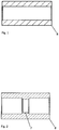
- FIG. 1 a spacer bushing 8 is shown, as known from the prior art, for. B. DE 10306790 A1 is known.
- FIG. 2 shows a section through a spacer bushing 8 with centering 7th
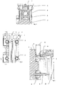
- FIG. 3 an assembled embodiment according to the prior art is disclosed.
- a flange 4 having exhaust pipe 3 is screwed by means of spacer bushing 8 and 6 fastening screw.
- FIG. 4 provides the embodiment according to FIG. 3
- the exhaust pipe 3, the flange 4 having the flange fastening holes 5 and the fastening screws 6 can be seen.
- FIG. 5 shows a side view according to FIG. 3 with exhaust pipe 3, which is connected by means of fastening screws 6 and spacers 8 with the cylinder head 2 of the internal combustion engine.
- the bending length 9 of the fastening screw 6 is also shown.
- the arrow marked with 10 represents the movement of the exhaust pipe 3 by thermal expansion.
- FIG. 6 an assembled embodiment of a spacer bushing 8 with centering 7 is disclosed.
- a flange 4 having exhaust pipe 3 is screwed by means of spacer bushing 8 and 6 fastening screw.
- FIG. 7 provides the embodiment according to FIG. 6
- the exhaust pipe 3, the flange 4 having the flange fastening holes 5 and the fastening screws 6 can be seen.
- FIG. 8 becomes a side view according to FIG. 6 with exhaust pipe 3, which is connected by means of fastening screws 6 and spacers 8 with the cylinder head 2 of the internal combustion engine shown.
- the bending length 9 of the fastening screw 6 is also shown.
- the arrow marked with 10 represents the movement of the exhaust pipe 3 by thermal expansion.
- the equivalent stress is a term used in strength theory and refers to a fictitious uniaxial stress that represents the same stress on material as a real multiaxial stress state.
- the actual three-dimensional load condition in the component consisting of normal stresses and shear stresses in all three spatial directions, can be compared directly with the characteristic values from the uniaxial tensile test (material properties, eg yield strength or tensile strength).
- material properties eg yield strength or tensile strength.
- the stress tensor tensor 2nd stage. In the general case, this contains six different voltage values (since the shear stresses are equal in pairs).
- the stress tensor into an excellent coordinate system (the major axis system)
- the shear stresses become zero and three excellent (normal) stresses (the principal stresses) describe the stress state of the system equivalent.
- comparison stress hypothesis The calculation rule for the formation of this scalar comparison voltage is called the comparison stress hypothesis or as the rule of failure.
- the comparison voltage is compared with permissible voltages. By choosing the hypothesis, it implicitly contains the failure mechanism and is therefore a value that expresses the endangerment of the component under the given load.
- hypotheses for calculating the reference stress. They are often summarized in technical mechanics as "strength hypotheses". The application depends on the material behavior and partly also on the field of application (if, for example, a standard requires the application of a specific hypothesis).
- shape change energy hypothesis also called shape change energy hypothesis (GEH for short) or Mises comparison stress
- This hypothesis is used for tough materials (eg steel) under static and alternating stress.
- the Mises equivalent stress is most commonly used in mechanical engineering and construction - for most common materials (not too brittle) under normal load (alternating, not jerky), the GEH can be used.
- Important fields of application are the calculations of shafts that are subject to both bending and torsion as well as steel construction.
- the GEH is designed in such a way that, given almost hydrostatic voltage states (equal voltages in all three spatial directions), a comparison voltage of zero results. Because plastic flow of metals is isochoric and even extreme hydrostatic pressures have no influence on the flow start.
- Var. 8 corresponds to the prior art z. B. according to DE 10306790 A1 with expansion length enlargement of the screw and clearance in the exhaust pipe for the sliding path.
- the screw head is usually mounted askew and tends to come loose on its own.
- Var. Figure 9 shows the present invention having additional local clearance for the screw in the sleeve, resulting in a changed point of introduction of the transverse force. This centering in the sleeve leads to less bending or tension of the screw, especially at the clamping point. A flat screw head after assembly is the result. The central paragraph in the sleeve ensures a corresponding mounting security (Poka Yoke). Details are in the following FIGS. 9 to 12 shown. A generally enlarged inside diameter sleeve would randomly attach to one side or the other during assembly and would not provide an improvement in bending stress due to the fact that the sleeve does not slide on the exhaust pipe flange. Loosening the screws on the end cylinders is thus definitely prevented.
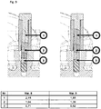
- FIG. 9 a deformation pattern of the screws is shown in comparison after heating.
- Var. 8 shows the prior art compared to the present invention (Var. 9) with the centering 7, which also in FIG. 2 and FIG. 6 is disclosed. It is noticeable that the bend in the prior art (Var. 8) takes place in the region of the lower end of the sleeve. In the present invention with the centering 7, the bending of the screw is realized recognizable in the centering 7.
- FIG. 10 discloses a deformation image of the screws after cooling.
- the state of the art is described in Var. 8, the present invention turns to Var. 9 dar.
- the centering 7, which also in FIG. 2 and FIG. 6 is disclosed, provides in comparison to the prior art that the voltage is significantly reduced, thus preventing a tearing of the screw.
- the bending of the screw in the prior art (Var. 8) takes place in the region of the lower end of the sleeve. In the present invention with the centering 7, the bending of the screw is realized recognizable in the centering 7.
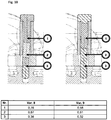
- the comparison voltage according to van Mises after heating in the third cycle is in FIG. 11 shown.
- the state of the art is described in Var. 8, the present invention turns to Var. 9 dar.
- the centering 7, which also in FIG. 2 and FIG. 6 is disclosed, provides in comparison to the prior art that the voltage is significantly reduced, thus preventing a tearing of the screw.
- the bending of the screw in the prior art (Var. 8) takes place in the region of the lower end of the sleeve. In the present invention with the centering 7, the bending of the screw is realized recognizable in the centering 7.
- FIG. 12 shows the comparison voltage according to van Mises after cooling in the third cycle.
- the state of the art is described in Var. 8, the present invention turns to Var. 9 dar.
- the centering 7, which also in FIG. 2 and FIG. 6 is disclosed, provides in comparison to the prior art that the voltage is significantly reduced, thus preventing a tearing of the screw.
- the bending of the screw in the prior art (Var. 8) takes place in the region of the lower end of the sleeve.
- the bending of the screw is realized recognizable in the centering 7. Loosening the screws on the end cylinders is thus prevented.
Landscapes
- Engineering & Computer Science (AREA)
- Chemical & Material Sciences (AREA)
- Combustion & Propulsion (AREA)
- Mechanical Engineering (AREA)
- General Engineering & Computer Science (AREA)
- Exhaust Silencers (AREA)
Description
- Die Erfindung betrifft eine Abstandhülse mit mittiger Schraubenzentrierung zur Befestigung von Abgasleitungen an Verbrennungsmotoren. Die Abstandshülsen dienen dazu, die Spannlänge der Schraubenverbindung zu vergrößern.
- Bisher bekannte Ausführungen, wie beispielsweise in der
DE 10306790 A1 offenbart, haben eine zylindrische Durchgangsbohrung. Der Nachteil der zylindrischen Durchgangsbohrung besteht darin, dass die Schraube meist so eng durch die Abstandsbuchse geführt wird, dass die Bewegungsfreiheit der Schraube stark eingeschränkt ist, dass es zu Undichtigkeit durch Lösen der Schraubverbindung kommen kann. - Es ist die Aufgabe der vorliegenden Erfindung, die oben genannten Nachteile zu vermeiden und eine Brennkraftmaschine mit sicherer Verschraubung zu schaffen.
- Die Aufgabe wird durch eine Brennkraftmaschine gemäß Anspruch 1 gelöst. Vorteilhaft daran ist, dass durch die Abstandhülse mit der mittigen Abstützung durch die größere Bewegungsfreiheit der Schraube der Vorspannungsverlust bzw. das Lösen der Schraubverbindung nicht auftreten kann. Die erfindungsgemäße Ausführung hat eine mittige Schraubenzentrierung und sorgt so für Bewegungsfreiheit der Schraube im Kopfbereich und im Bereich der Abstandshülsenauflage am Abgasrohr. Durch die Mittenzentrierung ist trotz der größeren Bewegungsfreiheit der Schraube die konzentrische Ausrichtung zwischen Schraube und Abstandhülse weiterhin gewährleistet.
- Weitere vorteilhafte Ausgestaltungen finden sich in den Unteransprüchen.
- Die Erfindung wird anhand einiger Ausführungsbeispiele unter Bezugnahme auf die Zeichnungen dargestellt, es zeigen:
- Fig. 1
- einen Schnitt durch eine Abstandsbuchse gemäß dem Stand der Technik
- Fig. 2
- einen Schnitt durch eine Abstandsbuchse mit Mittenzentrierung
- Fig. 3
- ein Ausführungsbeispiel gemäß dem Stand der Technik
- Fig. 4
- das Ausführungsbeispiel gemäß
Fig. 3 in Draufsicht - Fig. 5
- eine Seitenansicht gemäß
Fig. 3 - Fig. 6
- ein Ausführungsbeispiel mit Mittenzentrierung
- Fig. 7
- eine Draufsicht gemäß
Fig. 6 - Fig. 8
- eine Seitenansicht gemäß
Fig. 6 - Fig. 9
- Verformungsbild der Schrauben im Vergleich nach dem Aufheizen, Stand der Technik (Var. 8), Erfindung (Var. 9)
- Fig. 10
- Verformungsbild der Schrauben im Vergleich nach dem Abkühlen, Stand der Technik (Var. 8), Erfindung (Var. 9)
- Fig. 11
- Vergleichsspannung nach van Mises nach dem Aufheizen im dritten Zyklus, Stand der Technik (Var.8), Erfindung (Var. 9)
- Fig. 12
- Vergleichsspannung nach van Mises nach dem Abkühlen im dritten Zyklus, Stand der Technik (Var. 8), Erfindung (Var. 9)
- In
Figur 1 wird eine Abstandsbuchse 8 dargestellt, wie sie aus dem Stand der Technik, z. B.DE 10306790 A1 bekannt ist. -
Figur 2 zeigt einen Schnitt durch eine Abstandsbuchse 8 mit Mittenzentrierung 7. - In
Figur 3 wird ein montiertes Ausführungsbeispiel gemäß dem Stand der Technik offenbart. Am Zylinderkopf 2 ist das einen Flansch 4 aufweisende Abgasrohr 3 mittels Abstandsbuchse 8 und Befestigungsschraube 6 festgeschraubt. -
Figur 4 stellt das Ausführungsbeispiel gemäßFigur 3 in Draufsicht dar. Zu sehen sind das Abgasrohr 3, der die Flanschbefestigungslöcher 5 aufweisende Flansch 4 sowie die Befestigungsschrauben 6. -
Figur 5 zeigt eine Seitenansicht gemäßFigur 3 mit Abgasrohr 3, das mittels Befestigungsschrauben 6 und Abstandsbuchsen 8 mit dem Zylinderkopf 2 der Brennkraftmaschine verbunden ist. Die Biegelänge 9 der Befestigungsschraube 6 wird ebenfalls dargestellt. Der mit 10 gekennzeichnete Pfeil stellt die Bewegung des Abgasrohres 3 durch Wärmedehnung dar. - In
Figur 6 wird ein montiertes Ausführungsbeispiel einer Abstandsbuchse 8 mit Mittenzentrierung 7 offenbart. Am Zylinderkopf 2 ist das einen Flansch 4 aufweisende Abgasrohr 3 mittels Abstandsbuchse 8 und Befestigungsschraube 6 festgeschraubt. -
Figur 7 stellt das Ausführungsbeispiel gemäßFigur 6 in Draufsicht dar. Zu sehen sind das Abgasrohr 3, der die Flanschbefestigungslöcher 5 aufweisende Flansch 4 sowie die Befestigungsschrauben 6. - In
Figur 8 wird eine Seitenansicht gemäßFigur 6 mit Abgasrohr 3, das mittels Befestigungsschrauben 6 und Abstandsbuchsen 8 mit dem Zylinderkopf 2 der Brennkraftmaschine verbunden ist, gezeigt. Die Biegelänge 9 der Befestigungsschraube 6 wird ebenfalls dargestellt. Der mit 10 gekennzeichnete Pfeil stellt die Bewegung des Abgasrohres 3 durch Wärmedehnung dar. - In den
Figuren 11 und12 wird die Vergleichsspannung betrachtet. - Die Vergleichsspannung ist ein Begriff aus der Festigkeitslehre und bezeichnet eine fiktive einachsige Spannung, die dieselbe Materialbeanspruchung darstellt wie ein realer, mehrachsiger Spannungszustand.
- Damit kann der wirkliche dreidimensionale Belastungszustand im Bauteil, bestehend aus Normal-Spannungen und Schub-Spannungen in alle drei Raumrichtungen, direkt mit den Kennwerten aus dem einachsigen Zugversuch (Material-Kennwerte, z. B. Streckgrenze oder Zugfestigkeit) verglichen werden. Zur vollständigen Beschreibung des Spannungszustandes in einem Bauteil ist im Allgemeinen die Angabe des Spannungstensors (Tensor 2. Stufe) notwendig. Dieser enthält im allgemeinen Fall sechs verschiedene Spannungswerte (da die Schubspannungen paarweise gleich sind). Durch die Transformation des Spannungstensors in ein ausgezeichnetes Koordinatensystem (das Hauptachsensystem) werden die Schubspannungen zu Null und drei ausgezeichnete (Normal)Spannungen (die Hauptspannungen) beschreiben den Beanspruchungszustand des Systems äquivalent.
- Die Elemente des Vektors der Hauptspannungen bzw. des Spannungstensors können nun in ein Skalar überführt werden, das zwei Bedingungen genügen soll: zum einen soll es den Spannungszustand möglichst umfassend beschreiben (Äquivalenz kann hier nicht mehr erreicht werden: es treten immer Informationsverluste beim Übergang vom Vektor der Hauptspannungen zur Vergleichsspannung auf) zum Zweiten soll es auf jeden Fall eine versagensrelevante Information darstellen.
- Die Rechenvorschrift zur Bildung dieser skalaren Vergleichsspannung bezeichnet man als Vergleichsspannungshypothese bzw. als Versagensregel. Im Rahmen einer Tragfähigkeitsanalyse vergleicht man die Vergleichsspannung mit zulässigen Spannungen. Durch die Wahl der Hypothese enthält sie implizit den Versagensmechanismus und ist damit ein Wert, der die Gefährdung des Bauteils unter der gegebenen Beanspruchung ausdrückt.
- Die Wahl der jeweiligen Vergleichsspannungshypothese hängt also immer vom Festigkeitsverhalten des nachzuweisenden Materials sowie vom Lastfall (statisch, schwingend, Stoß) ab.
- Es gibt eine ganze Anzahl von Hypothesen zur Berechnung der Vergleichsspannung. Sie werden in der technischen Mechanik häufig unter dem Begriff "Festigkeitshypothesen" zusammengefasst. Die Anwendung hängt vom Materialverhalten und teilweise auch vom Anwendungsgebiet (wenn etwa eine Norm die Anwendung einer bestimmten Hypothese fordert) ab.
- Am häufigsten wird im Maschinenbau und im Bauwesen die Gestaltänderungsenergiehypothese nach von Mises angewendet.
- Nach der Gestaltänderungshypothese, auch Gestaltänderungsenergiehypothese (kurz: GEH) oder Mises-Vergleichsspannung genannt, tritt Versagen des Bauteils dann auf, wenn die Gestaltänderungsenergie einen Grenzwert überschreitet (s. auch Verzerrungen bzw. Deformation). Verwendet wird diese Hypothese für zähe Werkstoffe (z. B. Stahl) unter ruhender und wechselnder Beanspruchung. Die Mises-Vergleichsspannung wird im Maschinenbau und im Bauwesen am häufigsten eingesetzt -- für die meisten gängigen Materialien (nicht allzu spröde) unter normaler Belastung (wechselnd, nicht stoßartig) ist die GEH einsetzbar. Wichtige Anwendungsgebiete sind die Berechnungen von Wellen, die sowohl auf Biegung als auch auf Torsion beansprucht werden sowie der Stahlbau. Die GEH ist so konstruiert, dass sich bei nahezu hydrostatischen Spannungszuständen (gleich große Spannungen in allen drei Raumrichtungen), eine Vergleichsspannung von Null ergibt. Denn plastisches Fließen von Metallen ist isochor und selbst extreme hydrostatische Drücke haben keinen Einfluss auf den Fließbeginn.
- Var. 8 entspricht dem Stand der Technik z. B. gemäß
DE 10306790 A1 mit Dehnlängenvergrößerung der Schraube und Freigang im Abgasrohr für den Schiebeweg. Der Schraubenkopf ist in der Regel schief montiert und neigt zum selbstständigen Lösen. - Var. 9 zeigt die vorliegende Erfindung, die einen zusätzlichen lokalen Freigang für die Schraube in der Hülse aufweist, was zu einem geänderten Einleitungspunkt der Querkraft führt. Diese Mittenzentrierung in der Hülste führt zu geringerer Biegung bzw. Spannung der Schraube, insbesondere an der Einspannstelle. Ein ebener Schraubenkopf nach der Montage ist die Folge. Der mittige Absatz in der Hülse sorgt für eine entsprechende Montagesicherheit (Poka Yoke). Details sind in den nachfolgenden
Figuren 9 bis 12 dargestellt. Eine generell im Innendurchmesser vergrößerte Hülse würde sich bei der Montage zufällig an der einen oder anderen Seite anlegen und aufgrund der Tatsache, dass die Hülse auf dem Abgasrohrflansch nicht gleitet, keine Verbesserung hinsichtlich der Biegebeanspruchung bringen. Ein Lösen der Schrauben an den Endzylindern wird damit definitiv verhindert. - In
Figur 9 wird ein Verformungsbild der Schrauben im Vergleich nach dem Aufheizen dargestellt. Var. 8 zeigt hierbei den Stand der Technik im Vergleich zur vorliegenden Erfindung (Var. 9) mit der Mittenzentrierung 7, die auch inFigur 2 undFigur 6 offenbart wird. Hierbei fällt auf, dass die Biegung beim Stand der Technik (Var. 8) im Bereich des unteren Hülsenendes stattfindet. Bei der vorliegenden Erfindung mit der Mittenzentrierung 7 wird die Biegung der Schraube erkennbar im Bereich der Mittenzentrierung 7 realisiert. -
Figur 10 offenbart ein Verformungsbild der Schrauben im Vergleich nach dem Abkühlen. Der Stand der Technik wird in Var. 8 gezeigt, die vorliegende Erfindung stellt sich in Var. 9 dar. Die Mittenzentrierung 7, die auch inFigur 2 undFigur 6 offenbart wird, sorgt im Vergleich zum Stand der Technik dafür, dass die Spannung deutlich reduziert ist und somit ein Abreißen der Schraube verhindert. Die Biegung der Schraube beim Stand der Technik (Var. 8) erfolgt im Bereich des unteren Hülsenendes. Bei der vorliegenden Erfindung mit der Mittenzentrierung 7 wird die Biegung der Schraube erkennbar im Bereich der Mittenzentrierung 7 realisiert. - Die Vergleichsspannung nach van Mises nach dem Aufheizen im dritten Zyklus wird in
Figur 11 dargestellt. Der Stand der Technik wird in Var. 8 gezeigt, die vorliegende Erfindung stellt sich in Var. 9 dar. Die Mittenzentrierung 7, die auch inFigur 2 undFigur 6 offenbart wird, sorgt im Vergleich zum Stand der Technik dafür, dass die Spannung deutlich reduziert ist und somit ein Abreißen der Schraube verhindert. Die Biegung der Schraube beim Stand der Technik (Var. 8) erfolgt im Bereich des unteren Hülsenendes. Bei der vorliegenden Erfindung mit der Mittenzentrierung 7 wird die Biegung der Schraube erkennbar im Bereich der Mittenzentrierung 7 realisiert. -
Figur 12 zeigt die Vergleichsspannung nach van Mises nach dem Abkühlen im dritten Zyklus, Der Stand der Technik wird in Var. 8 gezeigt, die vorliegende Erfindung stellt sich in Var. 9 dar. Die Mittenzentrierung 7, die auch inFigur 2 undFigur 6 offenbart wird, sorgt im Vergleich zum Stand der Technik dafür, dass die Spannung deutlich reduziert ist und somit ein Abreißen der Schraube verhindert. Die Biegung der Schraube beim Stand der Technik (Var. 8) erfolgt im Bereich des unteren Hülsenendes. Bei der vorliegenden Erfindung mit der Mittenzentrierung 7 wird die Biegung der Schraube erkennbar im Bereich der Mittenzentrierung 7 realisiert. Ein Lösen der Schrauben an den Endzylindern wird damit verhindert. -
- 1
- Brennkraftmaschine
- 2
- Zylinderkopf der Brennkraftmaschine
- 3
- Abgasrohr
- 4
- Flansch
- 5
- Flanschbefestigungsloch
- 6
- Befestigungsschraube
- 7
- Mittenzentrierung
- 8
- Abstandsbuchse
- 9
- Biegelänge der Befestigungsschraube
- 10
- Bewegung des Abgasrohres durch Wärmedehnung
Claims (2)
- Brennkraftmaschine, umfassend wenigstens einen Zylinderkopf (2), wenigstens ein Abgasrohr (3) mit wenigstens einem Flansch (4), wobei der Flansch (4) wenigstens zwei Flanschbefestigungslöcher (5) aufweist, wenigstens zwei Befestigungsschrauben (6) zur Befestigung des Abgasrohrs (3) mit dem Zylinderkopf (2) der Brennkraftmaschine, wobei das Abgasrohr (3) mittels der Befestigungsschrauben (6) mit dem Zylinderkopf (2) demontierbar verbunden anordenbar ist, wobei im Wesentlichen zwischen dem Kopf der Befestigungsschraube (6) und dem Flanschloch (5) wenigstens eine Abstandsbuchse (8) angeordnet ist, dadurch gekennzeichnet, dass die Abstandsbuchse wenigstens eine Mittenzentrierung (7) aufweist.
- Verfahren zum Betreiben einer Brennkraftmaschine, dadurch gekennzeichnet, dass eine Vorrichtung nach Anspruch 1 zum Einsatz kommt.
Applications Claiming Priority (2)
| Application Number | Priority Date | Filing Date | Title |
|---|---|---|---|
| DE102012012703 | 2012-06-26 | ||
| PCT/EP2013/001764 WO2014000866A1 (de) | 2012-06-26 | 2013-06-14 | Brennkraftmaschine mit abstandhülse mit mittenzentrierung |
Publications (2)
| Publication Number | Publication Date |
|---|---|
| EP2895714A1 EP2895714A1 (de) | 2015-07-22 |
| EP2895714B1 true EP2895714B1 (de) | 2017-06-07 |
Family
ID=48747502
Family Applications (1)
| Application Number | Title | Priority Date | Filing Date |
|---|---|---|---|
| EP13734328.1A Active EP2895714B1 (de) | 2012-06-26 | 2013-06-14 | Brennkraftmaschine mit abstandhülse mit mittenzentrierung |
Country Status (3)
| Country | Link |
|---|---|
| US (1) | US9695775B2 (de) |
| EP (1) | EP2895714B1 (de) |
| WO (1) | WO2014000866A1 (de) |
Families Citing this family (1)
| Publication number | Priority date | Publication date | Assignee | Title |
|---|---|---|---|---|
| DE102015103180A1 (de) * | 2015-03-05 | 2016-09-08 | Schwing Gmbh | Zweizylinder-Kolbenpumpe |
Citations (1)
| Publication number | Priority date | Publication date | Assignee | Title |
|---|---|---|---|---|
| US5020204A (en) * | 1989-11-28 | 1991-06-04 | Eugene Desair | Tool for aligning the connecting of an exhaust manifold to an engine block |
Family Cites Families (18)
| Publication number | Priority date | Publication date | Assignee | Title |
|---|---|---|---|---|
| US2277536A (en) * | 1941-06-09 | 1942-03-24 | Lellia L Williams | Internal combustion engine |
| DE3742036A1 (de) | 1987-12-11 | 1989-06-22 | Bayerische Motoren Werke Ag | Befestigungsanordnung eines abgassammelrohres |
| DE19827276A1 (de) | 1997-10-02 | 1999-04-08 | Wolfgang Kleiner | Abgaskrümmerflansch für eine Verbrennungskraftmaschine |
| DE19916943A1 (de) | 1998-10-28 | 2000-05-04 | Vukic Roland | Flanschvorrichtung |
| JP4198841B2 (ja) | 1998-12-08 | 2008-12-17 | 本田技研工業株式会社 | エンジンにおける排気管の接続部構造およびエンジンへの排気管の接続方法 |
| DE19920822B4 (de) | 1999-05-06 | 2008-03-27 | Daimler Ag | Anordnung zur Befestigung eines Abgaskrümmers am Zylinderkopf einer Brennkraftmaschine |
| DE19960619A1 (de) | 1999-12-16 | 2001-07-05 | Daimler Chrysler Ag | Anordnung zur Befestigung eines Flansches |
| US7069883B2 (en) * | 2000-10-19 | 2006-07-04 | Atkins Robert M | Monitoring of closed circuit liquid cooling systems particularly in internal combustion engines |
| DE10141944A1 (de) | 2001-08-28 | 2003-04-03 | Bayerische Motoren Werke Ag | Montageflansch für Rohrverbindungen |
| DE10258319A1 (de) * | 2002-12-13 | 2004-07-15 | Elringklinger Ag | Flachdichtung, insbesondere Abgaskrümmerdichtung, sowie eine solche Dichtung aufnehmende Baugruppe |
| DE10306790A1 (de) | 2003-02-18 | 2004-09-02 | J. Eberspächer GmbH & Co. KG | Befestigungssystem und Verfahren zum Festlegen eines Auspuffkrümmers an einer Verbrennungskraftmaschine, und Verbrennungskraftmaschinenanordnung |
| JP2004270550A (ja) | 2003-03-07 | 2004-09-30 | Futaba Industrial Co Ltd | 排気マニホールド |
| DE102004010815A1 (de) * | 2004-03-05 | 2005-09-29 | Benteler Automobiltechnik Gmbh | Anordnung zur Fixierung eines Abgaskrümmers auf dem Zylinderkopf einer Brennkraftmaschine |
| JP2006274988A (ja) | 2005-03-30 | 2006-10-12 | Daihatsu Motor Co Ltd | 内燃機関の排気装置 |
| DE102006033357B4 (de) * | 2006-07-19 | 2009-04-09 | Elringklinger Ag | Einrichtung zur Bildung einer abgedichteten Verschraubung für den Anschluß einer Rohrleitung an einen Ausgang für ein die Einrichtung thermisch belastendes Strömungsmedium |
| DE102007002825B4 (de) * | 2007-01-19 | 2008-12-11 | Audi Ag | Klemmflanschanordnung zum Anschluss einer Auspuffanlage an eine Brennkraftmaschine |
| DE102007062660A1 (de) * | 2007-12-24 | 2009-06-25 | J. Eberspächer GmbH & Co. KG | Abgaskrümmer |
| JP2010116826A (ja) | 2008-11-12 | 2010-05-27 | Toyota Motor Corp | アルミニウム鋳物合金製排気マニホールド |
-
2013
- 2013-06-14 WO PCT/EP2013/001764 patent/WO2014000866A1/de not_active Ceased
- 2013-06-14 US US14/410,540 patent/US9695775B2/en active Active
- 2013-06-14 EP EP13734328.1A patent/EP2895714B1/de active Active
Patent Citations (1)
| Publication number | Priority date | Publication date | Assignee | Title |
|---|---|---|---|---|
| US5020204A (en) * | 1989-11-28 | 1991-06-04 | Eugene Desair | Tool for aligning the connecting of an exhaust manifold to an engine block |
Also Published As
| Publication number | Publication date |
|---|---|
| EP2895714A1 (de) | 2015-07-22 |
| WO2014000866A1 (de) | 2014-01-03 |
| US20150337754A1 (en) | 2015-11-26 |
| US9695775B2 (en) | 2017-07-04 |
Similar Documents
| Publication | Publication Date | Title |
|---|---|---|
| DE102008047596A1 (de) | Elastischer Gelenkkörper | |
| EP2846002A1 (de) | Gasturbine | |
| DE102014211949A1 (de) | Linearaktor, Hydrolager sowie Kraftfahrzeug mit einem derartigen Hydrolager bzw. Linearaktor | |
| DE102015004019A1 (de) | Schutzgitter; Verfahren zur Herstellung eines Schutzgitters für Lüfter | |
| DE102016108627A1 (de) | Bistabile Aktorvorrichtung mit einem Formgedächtniselement | |
| DE102017001007A1 (de) | Verfahren zur örtlichen Auswertung nichtlinearer Dehnpfade und ihrer zugehörigen Grenzdehnung mindestens eines durch einen Umformprozess umgeformten metallischen Blechwerkstoffes mittels einer Grenzformkurve | |
| EP2895714A1 (de) | Brennkraftmaschine mit abstandhülse mit mittenzentrierung | |
| DE102013200579A1 (de) | Schlauchleitung | |
| DE102010003594A1 (de) | Turbinenschaufel mit einem Schwingungsdämpfungselement | |
| DE102018005906A1 (de) | Stator und Motor | |
| DE102005021400A1 (de) | Vorrichtung und Verfahren zum Bereitstellen einer Klammer an einem Fluidkraft-Zylinder | |
| DE102009057176A1 (de) | Verfahren zur Autofrettage eines Bauteils | |
| DE202012102170U1 (de) | Vorrichtung zum Montieren/Demontieren eines Bauteils einer Windenergieanlage | |
| DE112018004418T5 (de) | Druck-feste Vorrichtung und Fluid-Druck-Zylinder | |
| WO2013037999A1 (de) | Verdichterschaufel und verfahren zu ihrer herstellung | |
| DE102005015150A1 (de) | Maschinengehäuse | |
| DE102013004950A1 (de) | Lastübertragungsbauteil | |
| DE102014007568A1 (de) | Befestigungsanordnung eines Statorelements einer elektrischen Maschine an einem Bauelement, insbesondere für einen Kraftwagen | |
| DE102012015595A1 (de) | Verfahren und Vorrichtung zum Manipulieren eines Objekts mittels eines Roboters | |
| EP3458224A1 (de) | Verfahren zur herstellung einer kolbenstangen-einheit sowie einer hohlen welle | |
| DE102017113072A1 (de) | Verfahren und Vorrichtung zum Schlagverfestigen von Übergangsradien einer Kurbelwelle | |
| DE102013110727A1 (de) | Verdichteranordnung für einen Turbolader | |
| DE102010010712B4 (de) | Halter zur Montage von Anbauteilen am Gehäuse eines Triebwerks, insbesondere eines Strahltriebwerks | |
| DE102011087475A1 (de) | Zeigerabziehwerkzeug | |
| EP1617086B1 (de) | Tragstrebe für Schutzgitter und Verfahren zu ihrer Herstellung |
Legal Events
| Date | Code | Title | Description |
|---|---|---|---|
| PUAI | Public reference made under article 153(3) epc to a published international application that has entered the european phase |
Free format text: ORIGINAL CODE: 0009012 |
|
| 17P | Request for examination filed |
Effective date: 20141127 |
|
| AK | Designated contracting states |
Kind code of ref document: A1 Designated state(s): AL AT BE BG CH CY CZ DE DK EE ES FI FR GB GR HR HU IE IS IT LI LT LU LV MC MK MT NL NO PL PT RO RS SE SI SK SM TR |
|
| AX | Request for extension of the european patent |
Extension state: BA ME |
|
| DAX | Request for extension of the european patent (deleted) | ||
| 17Q | First examination report despatched |
Effective date: 20160707 |
|
| GRAP | Despatch of communication of intention to grant a patent |
Free format text: ORIGINAL CODE: EPIDOSNIGR1 |
|
| INTG | Intention to grant announced |
Effective date: 20170209 |
|
| GRAS | Grant fee paid |
Free format text: ORIGINAL CODE: EPIDOSNIGR3 |
|
| AK | Designated contracting states |
Kind code of ref document: B1 Designated state(s): AL AT BE BG CH CY CZ DE DK EE ES FI FR GB GR HR HU IE IS IT LI LT LU LV MC MK MT NL NO PL PT RO RS SE SI SK SM TR |
|
| REG | Reference to a national code |
Ref country code: GB Ref legal event code: FG4D Free format text: NOT ENGLISH |
|
| GRAA | (expected) grant |
Free format text: ORIGINAL CODE: 0009210 |
|
| REG | Reference to a national code |
Ref country code: CH Ref legal event code: EP Ref country code: AT Ref legal event code: REF Ref document number: 899410 Country of ref document: AT Kind code of ref document: T Effective date: 20170615 |
|
| REG | Reference to a national code |
Ref country code: FR Ref legal event code: PLFP Year of fee payment: 5 |
|
| REG | Reference to a national code |
Ref country code: IE Ref legal event code: FG4D Free format text: LANGUAGE OF EP DOCUMENT: GERMAN |
|
| REG | Reference to a national code |
Ref country code: DE Ref legal event code: R096 Ref document number: 502013007441 Country of ref document: DE |
|
| REG | Reference to a national code |
Ref country code: NL Ref legal event code: MP Effective date: 20170607 |
|
| REG | Reference to a national code |
Ref country code: LT Ref legal event code: MG4D |
|
| PG25 | Lapsed in a contracting state [announced via postgrant information from national office to epo] |
Ref country code: GR Free format text: LAPSE BECAUSE OF FAILURE TO SUBMIT A TRANSLATION OF THE DESCRIPTION OR TO PAY THE FEE WITHIN THE PRESCRIBED TIME-LIMIT Effective date: 20170908 Ref country code: HR Free format text: LAPSE BECAUSE OF FAILURE TO SUBMIT A TRANSLATION OF THE DESCRIPTION OR TO PAY THE FEE WITHIN THE PRESCRIBED TIME-LIMIT Effective date: 20170607 Ref country code: NO Free format text: LAPSE BECAUSE OF FAILURE TO SUBMIT A TRANSLATION OF THE DESCRIPTION OR TO PAY THE FEE WITHIN THE PRESCRIBED TIME-LIMIT Effective date: 20170907 Ref country code: ES Free format text: LAPSE BECAUSE OF FAILURE TO SUBMIT A TRANSLATION OF THE DESCRIPTION OR TO PAY THE FEE WITHIN THE PRESCRIBED TIME-LIMIT Effective date: 20170607 Ref country code: LT Free format text: LAPSE BECAUSE OF FAILURE TO SUBMIT A TRANSLATION OF THE DESCRIPTION OR TO PAY THE FEE WITHIN THE PRESCRIBED TIME-LIMIT Effective date: 20170607 Ref country code: FI Free format text: LAPSE BECAUSE OF FAILURE TO SUBMIT A TRANSLATION OF THE DESCRIPTION OR TO PAY THE FEE WITHIN THE PRESCRIBED TIME-LIMIT Effective date: 20170607 |
|
| PG25 | Lapsed in a contracting state [announced via postgrant information from national office to epo] |
Ref country code: LV Free format text: LAPSE BECAUSE OF FAILURE TO SUBMIT A TRANSLATION OF THE DESCRIPTION OR TO PAY THE FEE WITHIN THE PRESCRIBED TIME-LIMIT Effective date: 20170607 Ref country code: BG Free format text: LAPSE BECAUSE OF FAILURE TO SUBMIT A TRANSLATION OF THE DESCRIPTION OR TO PAY THE FEE WITHIN THE PRESCRIBED TIME-LIMIT Effective date: 20170907 Ref country code: NL Free format text: LAPSE BECAUSE OF FAILURE TO SUBMIT A TRANSLATION OF THE DESCRIPTION OR TO PAY THE FEE WITHIN THE PRESCRIBED TIME-LIMIT Effective date: 20170607 Ref country code: SE Free format text: LAPSE BECAUSE OF FAILURE TO SUBMIT A TRANSLATION OF THE DESCRIPTION OR TO PAY THE FEE WITHIN THE PRESCRIBED TIME-LIMIT Effective date: 20170607 Ref country code: RS Free format text: LAPSE BECAUSE OF FAILURE TO SUBMIT A TRANSLATION OF THE DESCRIPTION OR TO PAY THE FEE WITHIN THE PRESCRIBED TIME-LIMIT Effective date: 20170607 |
|
| PG25 | Lapsed in a contracting state [announced via postgrant information from national office to epo] |
Ref country code: RO Free format text: LAPSE BECAUSE OF FAILURE TO SUBMIT A TRANSLATION OF THE DESCRIPTION OR TO PAY THE FEE WITHIN THE PRESCRIBED TIME-LIMIT Effective date: 20170607 Ref country code: SK Free format text: LAPSE BECAUSE OF FAILURE TO SUBMIT A TRANSLATION OF THE DESCRIPTION OR TO PAY THE FEE WITHIN THE PRESCRIBED TIME-LIMIT Effective date: 20170607 Ref country code: EE Free format text: LAPSE BECAUSE OF FAILURE TO SUBMIT A TRANSLATION OF THE DESCRIPTION OR TO PAY THE FEE WITHIN THE PRESCRIBED TIME-LIMIT Effective date: 20170607 Ref country code: CZ Free format text: LAPSE BECAUSE OF FAILURE TO SUBMIT A TRANSLATION OF THE DESCRIPTION OR TO PAY THE FEE WITHIN THE PRESCRIBED TIME-LIMIT Effective date: 20170607 |
|
| REG | Reference to a national code |
Ref country code: CH Ref legal event code: PL |
|
| PG25 | Lapsed in a contracting state [announced via postgrant information from national office to epo] |
Ref country code: PL Free format text: LAPSE BECAUSE OF FAILURE TO SUBMIT A TRANSLATION OF THE DESCRIPTION OR TO PAY THE FEE WITHIN THE PRESCRIBED TIME-LIMIT Effective date: 20170607 Ref country code: IS Free format text: LAPSE BECAUSE OF FAILURE TO SUBMIT A TRANSLATION OF THE DESCRIPTION OR TO PAY THE FEE WITHIN THE PRESCRIBED TIME-LIMIT Effective date: 20171007 Ref country code: SM Free format text: LAPSE BECAUSE OF FAILURE TO SUBMIT A TRANSLATION OF THE DESCRIPTION OR TO PAY THE FEE WITHIN THE PRESCRIBED TIME-LIMIT Effective date: 20170607 |
|
| REG | Reference to a national code |
Ref country code: DE Ref legal event code: R097 Ref document number: 502013007441 Country of ref document: DE |
|
| REG | Reference to a national code |
Ref country code: IE Ref legal event code: MM4A |
|
| PG25 | Lapsed in a contracting state [announced via postgrant information from national office to epo] |
Ref country code: MC Free format text: LAPSE BECAUSE OF FAILURE TO SUBMIT A TRANSLATION OF THE DESCRIPTION OR TO PAY THE FEE WITHIN THE PRESCRIBED TIME-LIMIT Effective date: 20170607 |
|
| PLBE | No opposition filed within time limit |
Free format text: ORIGINAL CODE: 0009261 |
|
| STAA | Information on the status of an ep patent application or granted ep patent |
Free format text: STATUS: NO OPPOSITION FILED WITHIN TIME LIMIT |
|
| PG25 | Lapsed in a contracting state [announced via postgrant information from national office to epo] |
Ref country code: DK Free format text: LAPSE BECAUSE OF FAILURE TO SUBMIT A TRANSLATION OF THE DESCRIPTION OR TO PAY THE FEE WITHIN THE PRESCRIBED TIME-LIMIT Effective date: 20170607 Ref country code: LI Free format text: LAPSE BECAUSE OF NON-PAYMENT OF DUE FEES Effective date: 20170630 Ref country code: CH Free format text: LAPSE BECAUSE OF NON-PAYMENT OF DUE FEES Effective date: 20170630 Ref country code: LU Free format text: LAPSE BECAUSE OF NON-PAYMENT OF DUE FEES Effective date: 20170614 Ref country code: IE Free format text: LAPSE BECAUSE OF NON-PAYMENT OF DUE FEES Effective date: 20170614 |
|
| 26N | No opposition filed |
Effective date: 20180308 |
|
| GBPC | Gb: european patent ceased through non-payment of renewal fee |
Effective date: 20170907 |
|
| PG25 | Lapsed in a contracting state [announced via postgrant information from national office to epo] |
Ref country code: SI Free format text: LAPSE BECAUSE OF FAILURE TO SUBMIT A TRANSLATION OF THE DESCRIPTION OR TO PAY THE FEE WITHIN THE PRESCRIBED TIME-LIMIT Effective date: 20170607 |
|
| REG | Reference to a national code |
Ref country code: BE Ref legal event code: MM Effective date: 20170630 |
|
| REG | Reference to a national code |
Ref country code: FR Ref legal event code: PLFP Year of fee payment: 6 |
|
| PG25 | Lapsed in a contracting state [announced via postgrant information from national office to epo] |
Ref country code: GB Free format text: LAPSE BECAUSE OF NON-PAYMENT OF DUE FEES Effective date: 20170907 |
|
| PG25 | Lapsed in a contracting state [announced via postgrant information from national office to epo] |
Ref country code: BE Free format text: LAPSE BECAUSE OF NON-PAYMENT OF DUE FEES Effective date: 20170630 |
|
| PG25 | Lapsed in a contracting state [announced via postgrant information from national office to epo] |
Ref country code: MT Free format text: LAPSE BECAUSE OF FAILURE TO SUBMIT A TRANSLATION OF THE DESCRIPTION OR TO PAY THE FEE WITHIN THE PRESCRIBED TIME-LIMIT Effective date: 20170607 |
|
| PG25 | Lapsed in a contracting state [announced via postgrant information from national office to epo] |
Ref country code: HU Free format text: LAPSE BECAUSE OF FAILURE TO SUBMIT A TRANSLATION OF THE DESCRIPTION OR TO PAY THE FEE WITHIN THE PRESCRIBED TIME-LIMIT; INVALID AB INITIO Effective date: 20130614 |
|
| REG | Reference to a national code |
Ref country code: AT Ref legal event code: MM01 Ref document number: 899410 Country of ref document: AT Kind code of ref document: T Effective date: 20180614 |
|
| PG25 | Lapsed in a contracting state [announced via postgrant information from national office to epo] |
Ref country code: CY Free format text: LAPSE BECAUSE OF FAILURE TO SUBMIT A TRANSLATION OF THE DESCRIPTION OR TO PAY THE FEE WITHIN THE PRESCRIBED TIME-LIMIT Effective date: 20170607 |
|
| PG25 | Lapsed in a contracting state [announced via postgrant information from national office to epo] |
Ref country code: MK Free format text: LAPSE BECAUSE OF FAILURE TO SUBMIT A TRANSLATION OF THE DESCRIPTION OR TO PAY THE FEE WITHIN THE PRESCRIBED TIME-LIMIT Effective date: 20170607 |
|
| PG25 | Lapsed in a contracting state [announced via postgrant information from national office to epo] |
Ref country code: AT Free format text: LAPSE BECAUSE OF NON-PAYMENT OF DUE FEES Effective date: 20180614 |
|
| PG25 | Lapsed in a contracting state [announced via postgrant information from national office to epo] |
Ref country code: TR Free format text: LAPSE BECAUSE OF FAILURE TO SUBMIT A TRANSLATION OF THE DESCRIPTION OR TO PAY THE FEE WITHIN THE PRESCRIBED TIME-LIMIT Effective date: 20170607 |
|
| PG25 | Lapsed in a contracting state [announced via postgrant information from national office to epo] |
Ref country code: PT Free format text: LAPSE BECAUSE OF FAILURE TO SUBMIT A TRANSLATION OF THE DESCRIPTION OR TO PAY THE FEE WITHIN THE PRESCRIBED TIME-LIMIT Effective date: 20170607 |
|
| PG25 | Lapsed in a contracting state [announced via postgrant information from national office to epo] |
Ref country code: AL Free format text: LAPSE BECAUSE OF FAILURE TO SUBMIT A TRANSLATION OF THE DESCRIPTION OR TO PAY THE FEE WITHIN THE PRESCRIBED TIME-LIMIT Effective date: 20170607 |
|
| PGFP | Annual fee paid to national office [announced via postgrant information from national office to epo] |
Ref country code: FR Payment date: 20250625 Year of fee payment: 13 |
|
| PGFP | Annual fee paid to national office [announced via postgrant information from national office to epo] |
Ref country code: DE Payment date: 20250814 Year of fee payment: 13 |
|
| PGFP | Annual fee paid to national office [announced via postgrant information from national office to epo] |
Ref country code: IT Payment date: 20250619 Year of fee payment: 13 |