EP2895317B1 - Système destiné à déposer un demi-produit en forme de bande avec rouleau presseur - Google Patents
Système destiné à déposer un demi-produit en forme de bande avec rouleau presseur Download PDFInfo
- Publication number
- EP2895317B1 EP2895317B1 EP13753876.5A EP13753876A EP2895317B1 EP 2895317 B1 EP2895317 B1 EP 2895317B1 EP 13753876 A EP13753876 A EP 13753876A EP 2895317 B1 EP2895317 B1 EP 2895317B1
- Authority
- EP
- European Patent Office
- Prior art keywords
- shaft
- casing
- pressure roller
- channel
- core
- Prior art date
- Legal status (The legal status is an assumption and is not a legal conclusion. Google has not performed a legal analysis and makes no representation as to the accuracy of the status listed.)
- Not-in-force
Links
Images


Classifications
-
- B—PERFORMING OPERATIONS; TRANSPORTING
- B29—WORKING OF PLASTICS; WORKING OF SUBSTANCES IN A PLASTIC STATE IN GENERAL
- B29C—SHAPING OR JOINING OF PLASTICS; SHAPING OF MATERIAL IN A PLASTIC STATE, NOT OTHERWISE PROVIDED FOR; AFTER-TREATMENT OF THE SHAPED PRODUCTS, e.g. REPAIRING
- B29C70/00—Shaping composites, i.e. plastics material comprising reinforcements, fillers or preformed parts, e.g. inserts
- B29C70/04—Shaping composites, i.e. plastics material comprising reinforcements, fillers or preformed parts, e.g. inserts comprising reinforcements only, e.g. self-reinforcing plastics
- B29C70/28—Shaping operations therefor
- B29C70/30—Shaping by lay-up, i.e. applying fibres, tape or broadsheet on a mould, former or core; Shaping by spray-up, i.e. spraying of fibres on a mould, former or core
- B29C70/38—Automated lay-up, e.g. using robots, laying filaments according to predetermined patterns
- B29C70/382—Automated fiber placement [AFP]
- B29C70/384—Fiber placement heads, e.g. component parts, details or accessories
-
- B—PERFORMING OPERATIONS; TRANSPORTING
- B29—WORKING OF PLASTICS; WORKING OF SUBSTANCES IN A PLASTIC STATE IN GENERAL
- B29C—SHAPING OR JOINING OF PLASTICS; SHAPING OF MATERIAL IN A PLASTIC STATE, NOT OTHERWISE PROVIDED FOR; AFTER-TREATMENT OF THE SHAPED PRODUCTS, e.g. REPAIRING
- B29C33/00—Moulds or cores; Details thereof or accessories therefor
- B29C33/02—Moulds or cores; Details thereof or accessories therefor with incorporated heating or cooling means
- B29C33/04—Moulds or cores; Details thereof or accessories therefor with incorporated heating or cooling means using liquids, gas or steam
- B29C33/044—Moulds or cores; Details thereof or accessories therefor with incorporated heating or cooling means using liquids, gas or steam in rolls calenders or drums
-
- B—PERFORMING OPERATIONS; TRANSPORTING
- B29—WORKING OF PLASTICS; WORKING OF SUBSTANCES IN A PLASTIC STATE IN GENERAL
- B29C—SHAPING OR JOINING OF PLASTICS; SHAPING OF MATERIAL IN A PLASTIC STATE, NOT OTHERWISE PROVIDED FOR; AFTER-TREATMENT OF THE SHAPED PRODUCTS, e.g. REPAIRING
- B29C65/00—Joining or sealing of preformed parts, e.g. welding of plastics materials; Apparatus therefor
- B29C65/02—Joining or sealing of preformed parts, e.g. welding of plastics materials; Apparatus therefor by heating, with or without pressure
- B29C65/10—Joining or sealing of preformed parts, e.g. welding of plastics materials; Apparatus therefor by heating, with or without pressure using hot gases (e.g. combustion gases) or flames coming in contact with at least one of the parts to be joined
- B29C65/103—Joining or sealing of preformed parts, e.g. welding of plastics materials; Apparatus therefor by heating, with or without pressure using hot gases (e.g. combustion gases) or flames coming in contact with at least one of the parts to be joined direct heating both surfaces to be joined
-
- B—PERFORMING OPERATIONS; TRANSPORTING
- B29—WORKING OF PLASTICS; WORKING OF SUBSTANCES IN A PLASTIC STATE IN GENERAL
- B29C—SHAPING OR JOINING OF PLASTICS; SHAPING OF MATERIAL IN A PLASTIC STATE, NOT OTHERWISE PROVIDED FOR; AFTER-TREATMENT OF THE SHAPED PRODUCTS, e.g. REPAIRING
- B29C65/00—Joining or sealing of preformed parts, e.g. welding of plastics materials; Apparatus therefor
- B29C65/02—Joining or sealing of preformed parts, e.g. welding of plastics materials; Apparatus therefor by heating, with or without pressure
- B29C65/10—Joining or sealing of preformed parts, e.g. welding of plastics materials; Apparatus therefor by heating, with or without pressure using hot gases (e.g. combustion gases) or flames coming in contact with at least one of the parts to be joined
- B29C65/106—Joining or sealing of preformed parts, e.g. welding of plastics materials; Apparatus therefor by heating, with or without pressure using hot gases (e.g. combustion gases) or flames coming in contact with at least one of the parts to be joined using flames coming in contact with at least one of the parts to be joined
-
- B—PERFORMING OPERATIONS; TRANSPORTING
- B29—WORKING OF PLASTICS; WORKING OF SUBSTANCES IN A PLASTIC STATE IN GENERAL
- B29C—SHAPING OR JOINING OF PLASTICS; SHAPING OF MATERIAL IN A PLASTIC STATE, NOT OTHERWISE PROVIDED FOR; AFTER-TREATMENT OF THE SHAPED PRODUCTS, e.g. REPAIRING
- B29C65/00—Joining or sealing of preformed parts, e.g. welding of plastics materials; Apparatus therefor
- B29C65/02—Joining or sealing of preformed parts, e.g. welding of plastics materials; Apparatus therefor by heating, with or without pressure
- B29C65/14—Joining or sealing of preformed parts, e.g. welding of plastics materials; Apparatus therefor by heating, with or without pressure using wave energy, i.e. electromagnetic radiation, or particle radiation
- B29C65/1403—Joining or sealing of preformed parts, e.g. welding of plastics materials; Apparatus therefor by heating, with or without pressure using wave energy, i.e. electromagnetic radiation, or particle radiation characterised by the type of electromagnetic or particle radiation
- B29C65/1412—Infrared [IR] radiation
-
- B—PERFORMING OPERATIONS; TRANSPORTING
- B29—WORKING OF PLASTICS; WORKING OF SUBSTANCES IN A PLASTIC STATE IN GENERAL
- B29C—SHAPING OR JOINING OF PLASTICS; SHAPING OF MATERIAL IN A PLASTIC STATE, NOT OTHERWISE PROVIDED FOR; AFTER-TREATMENT OF THE SHAPED PRODUCTS, e.g. REPAIRING
- B29C65/00—Joining or sealing of preformed parts, e.g. welding of plastics materials; Apparatus therefor
- B29C65/02—Joining or sealing of preformed parts, e.g. welding of plastics materials; Apparatus therefor by heating, with or without pressure
- B29C65/14—Joining or sealing of preformed parts, e.g. welding of plastics materials; Apparatus therefor by heating, with or without pressure using wave energy, i.e. electromagnetic radiation, or particle radiation
- B29C65/1403—Joining or sealing of preformed parts, e.g. welding of plastics materials; Apparatus therefor by heating, with or without pressure using wave energy, i.e. electromagnetic radiation, or particle radiation characterised by the type of electromagnetic or particle radiation
- B29C65/1425—Microwave radiation
-
- B—PERFORMING OPERATIONS; TRANSPORTING
- B29—WORKING OF PLASTICS; WORKING OF SUBSTANCES IN A PLASTIC STATE IN GENERAL
- B29C—SHAPING OR JOINING OF PLASTICS; SHAPING OF MATERIAL IN A PLASTIC STATE, NOT OTHERWISE PROVIDED FOR; AFTER-TREATMENT OF THE SHAPED PRODUCTS, e.g. REPAIRING
- B29C65/00—Joining or sealing of preformed parts, e.g. welding of plastics materials; Apparatus therefor
- B29C65/02—Joining or sealing of preformed parts, e.g. welding of plastics materials; Apparatus therefor by heating, with or without pressure
- B29C65/14—Joining or sealing of preformed parts, e.g. welding of plastics materials; Apparatus therefor by heating, with or without pressure using wave energy, i.e. electromagnetic radiation, or particle radiation
- B29C65/1429—Joining or sealing of preformed parts, e.g. welding of plastics materials; Apparatus therefor by heating, with or without pressure using wave energy, i.e. electromagnetic radiation, or particle radiation characterised by the way of heating the interface
- B29C65/1432—Joining or sealing of preformed parts, e.g. welding of plastics materials; Apparatus therefor by heating, with or without pressure using wave energy, i.e. electromagnetic radiation, or particle radiation characterised by the way of heating the interface direct heating of the surfaces to be joined
-
- B—PERFORMING OPERATIONS; TRANSPORTING
- B29—WORKING OF PLASTICS; WORKING OF SUBSTANCES IN A PLASTIC STATE IN GENERAL
- B29C—SHAPING OR JOINING OF PLASTICS; SHAPING OF MATERIAL IN A PLASTIC STATE, NOT OTHERWISE PROVIDED FOR; AFTER-TREATMENT OF THE SHAPED PRODUCTS, e.g. REPAIRING
- B29C65/00—Joining or sealing of preformed parts, e.g. welding of plastics materials; Apparatus therefor
- B29C65/02—Joining or sealing of preformed parts, e.g. welding of plastics materials; Apparatus therefor by heating, with or without pressure
- B29C65/14—Joining or sealing of preformed parts, e.g. welding of plastics materials; Apparatus therefor by heating, with or without pressure using wave energy, i.e. electromagnetic radiation, or particle radiation
- B29C65/1429—Joining or sealing of preformed parts, e.g. welding of plastics materials; Apparatus therefor by heating, with or without pressure using wave energy, i.e. electromagnetic radiation, or particle radiation characterised by the way of heating the interface
- B29C65/1454—Joining or sealing of preformed parts, e.g. welding of plastics materials; Apparatus therefor by heating, with or without pressure using wave energy, i.e. electromagnetic radiation, or particle radiation characterised by the way of heating the interface scanning at least one of the parts to be joined
- B29C65/1458—Joining or sealing of preformed parts, e.g. welding of plastics materials; Apparatus therefor by heating, with or without pressure using wave energy, i.e. electromagnetic radiation, or particle radiation characterised by the way of heating the interface scanning at least one of the parts to be joined once, i.e. contour welding
-
- B—PERFORMING OPERATIONS; TRANSPORTING
- B29—WORKING OF PLASTICS; WORKING OF SUBSTANCES IN A PLASTIC STATE IN GENERAL
- B29C—SHAPING OR JOINING OF PLASTICS; SHAPING OF MATERIAL IN A PLASTIC STATE, NOT OTHERWISE PROVIDED FOR; AFTER-TREATMENT OF THE SHAPED PRODUCTS, e.g. REPAIRING
- B29C65/00—Joining or sealing of preformed parts, e.g. welding of plastics materials; Apparatus therefor
- B29C65/02—Joining or sealing of preformed parts, e.g. welding of plastics materials; Apparatus therefor by heating, with or without pressure
- B29C65/14—Joining or sealing of preformed parts, e.g. welding of plastics materials; Apparatus therefor by heating, with or without pressure using wave energy, i.e. electromagnetic radiation, or particle radiation
- B29C65/16—Laser beams
- B29C65/1629—Laser beams characterised by the way of heating the interface
- B29C65/1632—Laser beams characterised by the way of heating the interface direct heating the surfaces to be joined
-
- B—PERFORMING OPERATIONS; TRANSPORTING
- B29—WORKING OF PLASTICS; WORKING OF SUBSTANCES IN A PLASTIC STATE IN GENERAL
- B29C—SHAPING OR JOINING OF PLASTICS; SHAPING OF MATERIAL IN A PLASTIC STATE, NOT OTHERWISE PROVIDED FOR; AFTER-TREATMENT OF THE SHAPED PRODUCTS, e.g. REPAIRING
- B29C65/00—Joining or sealing of preformed parts, e.g. welding of plastics materials; Apparatus therefor
- B29C65/02—Joining or sealing of preformed parts, e.g. welding of plastics materials; Apparatus therefor by heating, with or without pressure
- B29C65/14—Joining or sealing of preformed parts, e.g. welding of plastics materials; Apparatus therefor by heating, with or without pressure using wave energy, i.e. electromagnetic radiation, or particle radiation
- B29C65/16—Laser beams
- B29C65/1629—Laser beams characterised by the way of heating the interface
- B29C65/1654—Laser beams characterised by the way of heating the interface scanning at least one of the parts to be joined
- B29C65/1658—Laser beams characterised by the way of heating the interface scanning at least one of the parts to be joined scanning once, e.g. contour laser welding
-
- B—PERFORMING OPERATIONS; TRANSPORTING
- B29—WORKING OF PLASTICS; WORKING OF SUBSTANCES IN A PLASTIC STATE IN GENERAL
- B29C—SHAPING OR JOINING OF PLASTICS; SHAPING OF MATERIAL IN A PLASTIC STATE, NOT OTHERWISE PROVIDED FOR; AFTER-TREATMENT OF THE SHAPED PRODUCTS, e.g. REPAIRING
- B29C66/00—General aspects of processes or apparatus for joining preformed parts
- B29C66/01—General aspects dealing with the joint area or with the area to be joined
- B29C66/05—Particular design of joint configurations
- B29C66/10—Particular design of joint configurations particular design of the joint cross-sections
- B29C66/11—Joint cross-sections comprising a single joint-segment, i.e. one of the parts to be joined comprising a single joint-segment in the joint cross-section
- B29C66/112—Single lapped joints
- B29C66/1122—Single lap to lap joints, i.e. overlap joints
-
- B—PERFORMING OPERATIONS; TRANSPORTING
- B29—WORKING OF PLASTICS; WORKING OF SUBSTANCES IN A PLASTIC STATE IN GENERAL
- B29C—SHAPING OR JOINING OF PLASTICS; SHAPING OF MATERIAL IN A PLASTIC STATE, NOT OTHERWISE PROVIDED FOR; AFTER-TREATMENT OF THE SHAPED PRODUCTS, e.g. REPAIRING
- B29C66/00—General aspects of processes or apparatus for joining preformed parts
- B29C66/01—General aspects dealing with the joint area or with the area to be joined
- B29C66/05—Particular design of joint configurations
- B29C66/301—Three-dimensional joints, i.e. the joined area being substantially non-flat
-
- B—PERFORMING OPERATIONS; TRANSPORTING
- B29—WORKING OF PLASTICS; WORKING OF SUBSTANCES IN A PLASTIC STATE IN GENERAL
- B29C—SHAPING OR JOINING OF PLASTICS; SHAPING OF MATERIAL IN A PLASTIC STATE, NOT OTHERWISE PROVIDED FOR; AFTER-TREATMENT OF THE SHAPED PRODUCTS, e.g. REPAIRING
- B29C66/00—General aspects of processes or apparatus for joining preformed parts
- B29C66/50—General aspects of joining tubular articles; General aspects of joining long products, i.e. bars or profiled elements; General aspects of joining single elements to tubular articles, hollow articles or bars; General aspects of joining several hollow-preforms to form hollow or tubular articles
- B29C66/51—Joining tubular articles, profiled elements or bars; Joining single elements to tubular articles, hollow articles or bars; Joining several hollow-preforms to form hollow or tubular articles
- B29C66/53—Joining single elements to tubular articles, hollow articles or bars
- B29C66/532—Joining single elements to the wall of tubular articles, hollow articles or bars
- B29C66/5326—Joining single elements to the wall of tubular articles, hollow articles or bars said single elements being substantially flat
-
- B—PERFORMING OPERATIONS; TRANSPORTING
- B29—WORKING OF PLASTICS; WORKING OF SUBSTANCES IN A PLASTIC STATE IN GENERAL
- B29C—SHAPING OR JOINING OF PLASTICS; SHAPING OF MATERIAL IN A PLASTIC STATE, NOT OTHERWISE PROVIDED FOR; AFTER-TREATMENT OF THE SHAPED PRODUCTS, e.g. REPAIRING
- B29C66/00—General aspects of processes or apparatus for joining preformed parts
- B29C66/70—General aspects of processes or apparatus for joining preformed parts characterised by the composition, physical properties or the structure of the material of the parts to be joined; Joining with non-plastics material
- B29C66/73—General aspects of processes or apparatus for joining preformed parts characterised by the composition, physical properties or the structure of the material of the parts to be joined; Joining with non-plastics material characterised by the intensive physical properties of the material of the parts to be joined, by the optical properties of the material of the parts to be joined, by the extensive physical properties of the parts to be joined, by the state of the material of the parts to be joined or by the material of the parts to be joined being a thermoplastic or a thermoset
- B29C66/739—General aspects of processes or apparatus for joining preformed parts characterised by the composition, physical properties or the structure of the material of the parts to be joined; Joining with non-plastics material characterised by the intensive physical properties of the material of the parts to be joined, by the optical properties of the material of the parts to be joined, by the extensive physical properties of the parts to be joined, by the state of the material of the parts to be joined or by the material of the parts to be joined being a thermoplastic or a thermoset characterised by the material of the parts to be joined being a thermoplastic or a thermoset
- B29C66/7392—General aspects of processes or apparatus for joining preformed parts characterised by the composition, physical properties or the structure of the material of the parts to be joined; Joining with non-plastics material characterised by the intensive physical properties of the material of the parts to be joined, by the optical properties of the material of the parts to be joined, by the extensive physical properties of the parts to be joined, by the state of the material of the parts to be joined or by the material of the parts to be joined being a thermoplastic or a thermoset characterised by the material of the parts to be joined being a thermoplastic or a thermoset characterised by the material of at least one of the parts being a thermoplastic
-
- B—PERFORMING OPERATIONS; TRANSPORTING
- B29—WORKING OF PLASTICS; WORKING OF SUBSTANCES IN A PLASTIC STATE IN GENERAL
- B29C—SHAPING OR JOINING OF PLASTICS; SHAPING OF MATERIAL IN A PLASTIC STATE, NOT OTHERWISE PROVIDED FOR; AFTER-TREATMENT OF THE SHAPED PRODUCTS, e.g. REPAIRING
- B29C66/00—General aspects of processes or apparatus for joining preformed parts
- B29C66/80—General aspects of machine operations or constructions and parts thereof
- B29C66/83—General aspects of machine operations or constructions and parts thereof characterised by the movement of the joining or pressing tools
- B29C66/836—Moving relative to and tangentially to the parts to be joined, e.g. transversely to the displacement of the parts to be joined, e.g. using a X-Y table
- B29C66/8362—Rollers, cylinders or drums moving relative to and tangentially to the parts to be joined
-
- B—PERFORMING OPERATIONS; TRANSPORTING
- B29—WORKING OF PLASTICS; WORKING OF SUBSTANCES IN A PLASTIC STATE IN GENERAL
- B29C—SHAPING OR JOINING OF PLASTICS; SHAPING OF MATERIAL IN A PLASTIC STATE, NOT OTHERWISE PROVIDED FOR; AFTER-TREATMENT OF THE SHAPED PRODUCTS, e.g. REPAIRING
- B29C70/00—Shaping composites, i.e. plastics material comprising reinforcements, fillers or preformed parts, e.g. inserts
- B29C70/04—Shaping composites, i.e. plastics material comprising reinforcements, fillers or preformed parts, e.g. inserts comprising reinforcements only, e.g. self-reinforcing plastics
- B29C70/28—Shaping operations therefor
- B29C70/30—Shaping by lay-up, i.e. applying fibres, tape or broadsheet on a mould, former or core; Shaping by spray-up, i.e. spraying of fibres on a mould, former or core
- B29C70/38—Automated lay-up, e.g. using robots, laying filaments according to predetermined patterns
- B29C70/386—Automated tape laying [ATL]
- B29C70/388—Tape placement heads, e.g. component parts, details or accessories
-
- B—PERFORMING OPERATIONS; TRANSPORTING
- B65—CONVEYING; PACKING; STORING; HANDLING THIN OR FILAMENTARY MATERIAL
- B65H—HANDLING THIN OR FILAMENTARY MATERIAL, e.g. SHEETS, WEBS, CABLES
- B65H18/00—Winding webs
- B65H18/08—Web-winding mechanisms
- B65H18/10—Mechanisms in which power is applied to web-roll spindle
-
- B—PERFORMING OPERATIONS; TRANSPORTING
- B65—CONVEYING; PACKING; STORING; HANDLING THIN OR FILAMENTARY MATERIAL
- B65H—HANDLING THIN OR FILAMENTARY MATERIAL, e.g. SHEETS, WEBS, CABLES
- B65H18/00—Winding webs
- B65H18/08—Web-winding mechanisms
- B65H18/26—Mechanisms for controlling contact pressure on winding-web package, e.g. for regulating the quantity of air between web layers
-
- B—PERFORMING OPERATIONS; TRANSPORTING
- B29—WORKING OF PLASTICS; WORKING OF SUBSTANCES IN A PLASTIC STATE IN GENERAL
- B29C—SHAPING OR JOINING OF PLASTICS; SHAPING OF MATERIAL IN A PLASTIC STATE, NOT OTHERWISE PROVIDED FOR; AFTER-TREATMENT OF THE SHAPED PRODUCTS, e.g. REPAIRING
- B29C66/00—General aspects of processes or apparatus for joining preformed parts
- B29C66/70—General aspects of processes or apparatus for joining preformed parts characterised by the composition, physical properties or the structure of the material of the parts to be joined; Joining with non-plastics material
- B29C66/72—General aspects of processes or apparatus for joining preformed parts characterised by the composition, physical properties or the structure of the material of the parts to be joined; Joining with non-plastics material characterised by the structure of the material of the parts to be joined
- B29C66/721—Fibre-reinforced materials
- B29C66/7212—Fibre-reinforced materials characterised by the composition of the fibres
-
- B—PERFORMING OPERATIONS; TRANSPORTING
- B65—CONVEYING; PACKING; STORING; HANDLING THIN OR FILAMENTARY MATERIAL
- B65H—HANDLING THIN OR FILAMENTARY MATERIAL, e.g. SHEETS, WEBS, CABLES
- B65H2301/00—Handling processes for sheets or webs
- B65H2301/50—Auxiliary process performed during handling process
- B65H2301/51—Modifying a characteristic of handled material
- B65H2301/514—Modifying physical properties
- B65H2301/5143—Warming
- B65H2301/51432—Applying heat and pressure
-
- B—PERFORMING OPERATIONS; TRANSPORTING
- B65—CONVEYING; PACKING; STORING; HANDLING THIN OR FILAMENTARY MATERIAL
- B65H—HANDLING THIN OR FILAMENTARY MATERIAL, e.g. SHEETS, WEBS, CABLES
- B65H2404/00—Parts for transporting or guiding the handled material
- B65H2404/10—Rollers
- B65H2404/18—Rollers composed of several layers
- B65H2404/185—Rollers composed of several layers easy deformable
-
- B—PERFORMING OPERATIONS; TRANSPORTING
- B65—CONVEYING; PACKING; STORING; HANDLING THIN OR FILAMENTARY MATERIAL
- B65H—HANDLING THIN OR FILAMENTARY MATERIAL, e.g. SHEETS, WEBS, CABLES
- B65H2404/00—Parts for transporting or guiding the handled material
- B65H2404/40—Shafts, cylinders, drums, spindles
- B65H2404/43—Rider roll construction
-
- B—PERFORMING OPERATIONS; TRANSPORTING
- B65—CONVEYING; PACKING; STORING; HANDLING THIN OR FILAMENTARY MATERIAL
- B65H—HANDLING THIN OR FILAMENTARY MATERIAL, e.g. SHEETS, WEBS, CABLES
- B65H2701/00—Handled material; Storage means
- B65H2701/10—Handled articles or webs
- B65H2701/17—Nature of material
- B65H2701/172—Composite material
Definitions
- the present invention relates to a pressure roller for depositing sheet semifinished product and a deposition system with such a pressure roller.
- thermoset fiber composite components which have a proportion of fibers and a proportion of plastic as a matrix, have hitherto mainly been produced as thermoset fiber composite components, with a thermosetting plastic being used as the plastic.
- thermosetting plastic with a thermoplastic material
- thermoplastic material opens up new possibilities for the conception of fiber composite components, but also new challenges in the manufacture and manufacture of such components.
- fiber composite components in particular those with thermoplastics as a plastic component, are manufactured by inserting semi-finished products into a mold or by wrapping a core with a semi-finished product.
- a semifinished product which is called (from the English pre in pre gnated) more commonly known as prepreg, be used with a plastic matrix preimpregnated reinforcing fibers.
- Such a semifinished product has, on the one hand, reinforcing fibers, for example glass, basalt or carbon fibers, and, on the other hand, a plastic matrix in which the reinforcing fibers are embedded.
- reinforcing fibers for example glass, basalt or carbon fibers
- plastic matrix in which the reinforcing fibers are embedded.
- the material of the plastic matrix are polyethylene (PE), polypropylene (PP), polyamide (PA), polyphenylene sulfide (PPS) or polyether ketone (PEEK).
- One possibility for producing a fiber composite component from a sheet-like thermoplastic semifinished product is to deposit the sheet-like semifinished product on a mold or a core with simultaneous heating of the semifinished product. In this way, the semifinished when depositing on the one hand to the contour of the mold, on the other hand, it is also welded to other layers of the same semi-finished product.
- inter alia lasers are used which heat the semifinished product at the place of deposition by absorption of the laser radiation in the semifinished product itself.
- Rotationally symmetrical components are produced in the so-called winding technique, d. H. the semifinished product is wound up on a core.
- Flat components are made by placing the semifinished product on a mold.
- both the winding and the laying are referred to as depositing.
- the semifinished product When placing the semifinished product on a mold or a core, the semifinished product must also be pressed against the mold or the core, so that the semifinished product assumes the contour of the core or the mold and with the already deposited material as a result of solidification due to cooling consolidated the matrix to a component.
- pressure rollers made of elastomers are used in the prior art.
- silicone is used here as an elastomeric material.
- these elastomer pressure rollers have high wear at high processing temperatures and therefore often require replacement. A trouble-free production process is not possible here.
- the DE 1938965 discloses a roller for the pressure treatment of webs, which is surrounded by a rubber layer which forms the pressing surface of the roller.
- a pressing device for pressing fiber-reinforced thermoplastic materials having a base body and provided on a surface of the base body Anpress harsh.
- the contact pressure layer is in this case formed with an inorganic material, preferably a ceramic material, and has a flexibility due to its structure, which allows it to adapt to the contour of a mold.
- the patent US 5,078,821 discloses a pressurized tube as a pressure roller having an inner bladder for pressurizing.
- the bladder in turn, is surrounded by a metallic retainer which exhibits a deformation similar to a fiber reinforced elastomeric tire.
- the outer surface of the tube is formed by a metallic shell which engages the thermoplastic material to be deposited.
- the international patent application WO2010 / 031 364 A1 discloses a Antikkissen with an air chamber pressurized with compressed air, wherein the Antikkissen consists of a base material made of silicone and on the outer surface of the base material, a rubber layer and on the outer surface of the rubber layer, in turn, a metal fabric is applied.
- a depositing system for depositing sheet semifinished product is provided with a pressure roller for depositing the web-shaped semifinished product with a shaft for rotatably supporting the pressure roller, an at least partially elastically deformable hollow cylindrical shell and two radially from the shaft outwardly extending spacer, the shell being held by the spacers at a distance from the shaft such that the shell extends between the spacers and concentrically around the shaft such that the spacers form the top surfaces of the hollow cylinder formed by the shell and the shell and the spacers defining an interior of the pressure roller, wherein the jacket is made of a metal sheet and the jacket has a lateral surface which forms the surface to be pressed of the pressure roller and wherein the jacket at its first and two in the axial direction each end has a radially inwardly extending collar, each of the collar is connected in each case with a spacer.
- Such a pressure roller in which the pressing surface is formed by an elastically deformable hollow cylindrical lateral surface of the roller, has the advantage that the roller elastically adapts to the contour of the mold or of the core on which the sheet-like semi-finished product is to be deposited , At the same time, the jacket can be made of a low-wear material.
- a sheet-like semi-finished product is understood to mean a semifinished product which has a considerably greater extent in one direction than in the other directions, so that it can be wound onto rolls or spools and pulled off from them in the production process.
- a semifinished product may for example be in the form of a strand or a band, wherein the cross section of the semifinished product is not limited to any particular shapes. However, typical cross-sectional shapes are round, rectangular or square.
- the elastically deformable portion of the shell has a wall thickness in a range of 0.1 mm to 2 mm, preferably in a range of 0.25 mm to 1 mm, particularly preferably 0.4 mm.
- the spacer defines a distance between the hollow cylindrical shell and the shaft, with which the pressure roller can be rotatably supported, the elastic deformability of the hollow cylindrical shell is ensured and limited.
- the pressure roller on two spacers, and the jacket extends between the two spacers such that the spacers form the top surfaces of the hollow cylinder formed by the shell and the jacket and the spacers together define an interior of the pressure roller.
- the jacket has at its first and second ends in the axial direction in each case a radially inwardly extending collar, wherein each of the collar is connected in each case with a spacer.
- the hollow cylindrical shell can be clamped between the spacers and fastened to them.
- the jacket and the radially inwardly extending collar is made in one piece at its axial ends.
- Such a one-piece design of the collar and the shell can be realized in that the jacket with the collar of a solid hollow cylinder, which has at least one wall thickness corresponding to the radial extent of the collar, starting from the outer surface of the shell made, d. H. especially turned, milled or eroded.
- a stop element is provided radially in the direction of the shaft of the shell spaced apart, which forms a stop for the elastic deformation of the shell. In this way, the elastic deformation of the shell is limited so that the deformation can not cause damage to the shell.
- the stop member has a radial distance from the jacket in a range of 0.5 mm to 5 mm, and preferably 1 mm. It can be assumed that the distance between the jacket and the stop element in the axial direction is constant, so that the specified range of values relates to different embodiments.
- annular gap between shell and spacer is formed, which can be used in other embodiments for guiding a cooling fluid, which cools the jacket of the pressure roller.
- the annular gap extends in the axial direction over the entire elastically deformable section of the jacket.
- the shaft of the pressure roller is at least partially a hollow shaft having a first axially extending channel which is connected in the radial direction with the interior of the pressure roller for supplying a fluid in an interior of the pressure roller and a second in the axial direction extending channel, which is connected in the radial direction with the interior of the pressure roller, for discharging a fluid from the interior.
- a pressure roller can be realized in which the jacket can be tempered by a fluid flowing past, i. especially coolable, is.
- a fluid which is suitable for controlling the temperature of the jacket is, in particular, a gas, in particular compressed air, or a liquid, in particular oil or water.
- first axially extending channel of the shaft extends from a first end of the shaft into it and the second axially extending channel extends from the opposite end of the shaft into it.
- the two channels are in particular designed as blind holes and each connected via extending in the radial direction channel sections with the interior of the pressure roller. In this way can be supplied through the one channel fluid while it can be discharged through the other channel.
- the pinch roller has a fluid channel having a first radial portion extending radially outwardly from the first channel of the shaft to an inner surface of the shell, having at least one axial portion extending from a radially outer end of the first extending radially from the axial portion, wherein the inner surface of the shell forms a wall of the axial portion, and having at least a second radial portion which extends from the inner surface of the shell radially inwardly to the second channel of the shaft.
- At least portions of such a fluid channel can be realized in one embodiment of the invention in that the pressure roller has a radially outwardly extending from the shaft core, which is sealed against the shaft and the at least one Having radially outwardly extending aperture which forms at least a portion of the first radial portion of the fluid channel and which is connected to the first channel of the shaft.
- At least one further portion of the fluid channel may be provided by the pressure roller having a cooling ring concentric with the shell, radially inwardly spaced from the shell, the cooling ring having at least one radially extending first aperture and Cooling ring is sealed against the core such that the radially extending aperture of the core and the radially extending aperture of the cooling ring together form the first radial portion of the fluid channel.
- the cooling ring forms not only a part of the first radial portion of the fluid channel but also preferably together with the jacket the axial portion of the fluid channel.
- cooling ring can serve as a stop element for the elastically deformable jacket, as previously stated.
- the cooling ring has at least one radially extending second aperture which opens into a first volume delimited by the core, on the one hand, and a first spacer, and which is connected to the second channel of the shaft.
- the radially extending second aperture of the cooling ring as well as the volume defined by the core, on the one hand, and the first spacer, on the other hand, together form the second radially extending portion of the fluid channel.
- the core is arranged in the axial direction such that two axial sections of the fluid channel are formed and the cooling ring has at least one second radial opening which opens into a second volume bounded on the one hand by the core and on the other hand by a second spacer becomes.
- a supply of the fluid is provided in a central position from the shaft to the shell, wherein the fluid flows in two axial directions on the jacket when reaching the shell and then flows in two directions in the radial direction back to the shaft.
- the core has at least one axially extending aperture bounding the first volume delimited by the core on the one hand and the first spacer and the second volume delimiting the core on the one hand and the second spacer on the other hand becomes, connects.
- the deposition system comprises a heating system which is adapted to operate in operation with a preferably thermoplastic semi-finished product in the region in front of or at the pressure roller, i. in the process zone, heated.
- a heating system are, for example, a device for generating an open flame, a device for generating a Schugasstrahls, but also infrared or microwave radiation sources.
- the heating system is a laser that is adapted to operate during operation a semi-finished product in front of or on the pressure roller, d. H. in the process zone, irradiated.
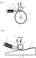
- FIG. 1 shows a schematic sectional view through an arrangement for winding a web-shaped semifinished product 1 onto a shaping core 2.
- the web-shaped semifinished product 1 is a thermoplastic prepreg material with a matrix of a thermoplastic material and reinforcing fibers, here carbon fibers.
- the core 2 on which the semifinished product 1 is wound is, for example, a lost mold for producing a pressure vessel.
- the web-shaped semifinished product 1 is withdrawn from a supply reel and fed to the process zone 3.
- the process zone 3 ie immediately before the semifinished product 1 is wound on the core 2, it is heated by means of laser radiation 4, which is absorbed by the semifinished product 1 itself, and then pressed against the core 2 in the heated state with the aid of a pressure roller 5 such that the molten material of the semifinished product assumes the shape of the core.
- the laser radiation is provided by a laser 7 and blasted onto the process zone 3.
- By melting the semi-finished product 1 is not only plastically deformable, but the material is also with underlying material webs (in the illustration of FIG. 1 not shown) fused. Behind the process zone 3 has become the processed fiber-reinforced plastic 6 from the semifinished product 1, which forms the plastic molding.
- the semifinished product can also be placed on a mold 2 ', so that the finished processed material 6 can then be removed from the mold 2' and has its contour.
- FIG. 2 Such an arrangement for depositing the semifinished product 1 is shown.
- the arrangement consists essentially of a pressure roller 5, which presses the semifinished product 1 against the mold 2 '.
- the semifinished product is again heated by laser radiation 4, which is generated by means of a laser 7.
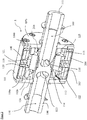
- FIG. 3 shows a perspective sectional view of the pressure roller according to the invention 5.
- the essential components of the pressure roller 5 namely a shaft 100 for rotatably supporting the pressure roller 5, an elastically deformable hollow cylindrical shell 101, two spacers 102a, 102b, which hold the shell 101 at a distance from the shaft 100 such that the shell 101 extends concentrically around the shaft 100.
- the pressure roller 5 has in its interior a core 103 and a cooling ring 104.
- FIGS. 4 and 5 show broken away perspective views of the combination of spacers 102a, 102b and sheath 101 (FIG. FIG. 4 ) or shell 101 alone ( FIG. 5 ).
- the jacket 101 consists essentially of sheet steel, so that its outer shell surface 105 is elastically deformable. This deformability of the shell 101 is due to the material property of the thin sheet on the one hand, but on the other hand, the support of the shell 101 between the two spacers 102a, 102b, which clamp the jacket.
- the shell 101 In order to clamp the shell 101 between the spacers 102a, 102b, the shell 101 has two integrally connected thereto collar 106a, 106b, which extend from the outer shell surface 105 in the radial direction inwardly and which are provided with mounting holes 107, so that the jacket can be screwed over its collars 106a, 106b with the spacers 102a and 102b.
- the cooling ring 104 also fulfills the task of a stop element for an elastic deformation of the shell.
- the wall thickness of the shell 101 in its elastically deformable portion 108 in the illustrated embodiment is about 0.4 mm.
- the cooling ring 104 is in FIG. 7 in the assembled, but not installed state shown in perspective.
- FIG. 6 A likewise perspective view of the core 103 can be found in FIG. 6 .
- the selected construction of the pressure roller 5 with cooling ring 104 and core 103 in its inner space 126 makes it possible to cool the shell 101 and in particular its elastically deformable portion 108 during operation of the pressure roller 5.
- the semi-finished product to be deposited has a markedly elevated temperature with the aid of the laser.
- a cooling channel is realized, which starting from the shaft 100, a stream of cooling fluid, in particular compressed air, first in the radial outward direction until reaching the shell 101, then in the axial direction along the shell 101 and again in the radial Direction back to the shaft 100 allows.
- the shaft 100 is a hollow shaft with two axially extending channels 109, 110.
- the axial channel 109 of the shaft 100 extends from the first end 111 to approximately the axial center of the pinch roller 5 and there has a in Radial direction extending connecting portion 112, via which the axial channel 109 of the shaft 100 with the interior 126 of the pressure roller 5 is in communication.
- the second axial channel 110 of the shaft 100 is separated from the first axial channel 109.
- the second axial channel 110 is connected via a radial connecting portion 113 with the inner space 126 of the pressure roller 5 in connection.
- the axial channel 109 of the shaft serves to supply a cooling fluid
- the second axial channel 110 serves for the discharge of the cooling fluid
- the core 103 is also arranged in the axial center of the pressure roller 5 and placed there sealed to the shaft 100.
- two circumferential sealing rings 114 and 115, respectively, are provided between the shaft and the core.
- Fluid exiting the shaft 100 circumferentially distributes around the shaft in a distribution groove 116.
- the core faces as shown FIG. 6 can be taken well in the radial direction extending openings 117, which are on a first side with the distribution groove 116 of the shaft in communication and on its second, radially outer side with an annular space 118.
- Through these radial openings 117 is a first part of a formed in the radial direction extending cooling passage portion.
- the core 103 in turn is sealed against the cooling ring 104 and fluid entering the annulus 118 is passed through apertures 119 located between the seals 120 and 121 between the core 103 and the cooling ring 104 in the radial direction.
- the radial openings 119 of the cooling ring 104 are well in the illustration FIG. 7 to recognize. These radial openings 119 of the cooling ring 104 form a second part of a first radial section of the fluid channel for guiding a cooling fluid.
- the radial openings 119 of the cooling ring 104 open into the previously discussed annular gap 122 between the elastically deformable portion 108 of the shell 101 and the cooling ring 104. In this annular gap 122, the cooling fluid distributed in the circumferential direction of the shell 101. In addition, the cooling fluid flows in axial Direction through the annular gap 122 past the inner wall of the shell 101 and cools it in this way.
- radial openings 119 of the cooling ring 104 thus form two substantially axial portions of the fluid channel, d. H. on the one hand in the direction of the first collar 106a of the shell 101 and on the other in the direction of the second collar 106b of the shell 101st
- Cooling fluid which reaches the collars 106a, 106b enters from there its return path to the shaft 100.
- This return path of the fluid from the inner wall of the shell 101 is effected by second openings 123, which are arranged in the radial direction in the cooling ring 104.
- These radial openings 123 of the cooling ring 104 form a first part of a second radial section of the fluid channel in the pressure roller 5.
- the fluid flows into two interior volumes 124, 125 within the interior 126 of the pressure roller 5.
- These volumes 124, 125 are from the core 103, the shaft 100 and in one case the spacer 102a and the other Case limited by the spacer 102b. Through these volumes 124, 125 can be a stream of the cooling fluid in the radial direction on the shaft take place. While the volume 124 is in direct fluid communication with the second axial channel 110 of the shaft 100, this is not the case for the second volume 125. Nevertheless, in order for the fluid from the second volume to be able to flow away via the second channel 110 of the shaft 100, the core has axial openings 126 which connect the second volume 125 to the first volume 124 and thus to the second channel 110 of the shaft 100.
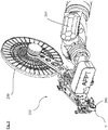
- FIG. 8 shows still a broken-away view of a depositing system according to the invention with the above-described pinch roller 5. Clearly visible is the stock or Abziehspule 200 for the semi-finished product, from which the semi-finished product of the process zone 201 in the region of the pressure roller 5 is supplied.
- the entire deposition system 202 is mounted on a robot arm 203 so that the deposition system can be guided over a mold or around a core.
Landscapes
- Engineering & Computer Science (AREA)
- Mechanical Engineering (AREA)
- Physics & Mathematics (AREA)
- Electromagnetism (AREA)
- Health & Medical Sciences (AREA)
- Toxicology (AREA)
- Chemical & Material Sciences (AREA)
- Optics & Photonics (AREA)
- Combustion & Propulsion (AREA)
- Robotics (AREA)
- Composite Materials (AREA)
- Rolls And Other Rotary Bodies (AREA)
Claims (11)
- Système (202) destiné à déposer un demi-produit en forme de bande avec un rouleau presseur (5) pour déposer le demi-produit (1) en forme de bande, avec
un axe (100) pour un support à rotation du rouleau presseur (5),
une enveloppe (101) en forme de cylindre creux au moins partiellement élastique et
deux espaceurs (102a, 102b) s'étendant radialement vers l'extérieur à partir de l'axe (100),
l'enveloppe (101) étant maintenue par les espaceurs (102a, 102b) à une distance telle de l'axe (100) que l'enveloppe (101) s'étend entre les espaceurs (102a, 102b) et de manière concentrique autour de l'axe (100), si bien que les espaceurs (102a, 102b) forment les surfaces de couvercle du cylindre creux formées par l'enveloppe (101) et les espaceurs (102a, 102b) délimitent un volume intérieur (108) du rouleau presseur (5),
l'enveloppe (101) étant fabriquée en une tôle métallique et l'enveloppe (101) présentant une surface d'enveloppe (105) qui constitue la surface d'appui du rouleau presseur (5),
caractérisé en ce que l'enveloppe (101) comprend à ses première et deuxième extrémités (111), vu dans la direction axiale, un rebord respectif (106a, 106b) s'étendant radialement vers l'intérieur, chacun des rebords (106a, 106b) étant relié respectivement à un espaceur (102a, 102b). - Système pour déposer (202) selon la revendication 1, caractérisé en ce que l'enveloppe (101) présente une épaisseur de paroi dans une plage de 0,1 mm à 2 mm, de préférence dans une plage de 0,25 mm à 1 mm et de manière particulièrement préférée de 0,4 mm.
- Système pour déposer (202) selon la revendication 1 ou 2, caractérisé en ce que, en direction de l'axe (100), radialement espacé de l'enveloppe (101), il est prévu un élément de butée qui constitue une butée pour une déformation élastique de l'enveloppe.
- Système pour déposer (202) selon la revendication 3, caractérisé en ce que l'espaceur (102a, 102b) présente un espacement radial de l'enveloppe (101) dans une plage de 0,5 mm à 5 mm et de préférence de 1 mm.
- Système pour déposer (202) selon l'une des revendications 1 à 4, caractérisé en ce que l'axe (100) est au moins partiellement un axe creux avec un premier canal (109) s'étendant dans la direction axiale et qui est relié dans la direction radiale à un volume intérieur (126) du rouleau presseur (5) pour emmener un fluide dans le volume intérieur (126), et avec un deuxième canal (110) s'étendant dans la direction axiale et qui est relié dans la direction radiale au volume intérieur (126) du rouleau presseur (5) pour évacuer un fluide du volume intérieur (126).
- Système pour déposer (202) selon la revendication 5, caractérisé en ce que le rouleau presseur (5) comprend un canal pour fluide avec une première zone radiale qui s'étend du premier canal (109) de l'axe (100) radialement vers l'extérieur vers une surface intérieure de l'enveloppe, avec au moins une zone axiale qui s'étend axialement à partir d'une extrémité radialement extérieure de la première zone radiale, la surface intérieure de l'enveloppe formant une paroi de la zone axiale, et avec au moins une deuxième zone radiale qui s'étend à partir de la surface intérieure de l'enveloppe radialement vers l'intérieur vers le deuxième canal (110) de l'axe (100).
- Système pour déposer (202) selon la revendication 6, caractérisé en ce que le rouleau presseur (5) comprend un noyau (103) s'étendant à partir de l'axe (100) radialement vers l'extérieur, qui est rendu étanche par rapport à l'axe (100) et qui comprend au moins un passage (117) s'étendant radialement vers l'extérieur, qui forme au moins une partie de la première zone radiale du canal pour fluide et est relié au premier canal (109) de l'axe (100).
- Système pour déposer (202) selon la revendication 7, caractérisé en ce que le rouleau presseur (5) comprend un anneau de refroidissement (104) concentrique par rapport à l'enveloppe (101) et espacé de l'enveloppe (101) radialement vers l'intérieur, l'anneau de refroidissement (104) comprenant au moins un premier passage (119) s'étendant radialement et l'anneau de refroidissement (104) étant rendu étanche par rapport au noyau (103) d'une manière telle que le premier passage (117) du noyau (103), s'étendant radialement, et le passage (119) de l'anneau de refroidissement (104), s'étendant radialement, constituent ensemble la première zone radiale du canal pour fluide.
- Système pour déposer (202) selon la revendication 8, caractérisé en ce que l'anneau de refroidissement (104) comprend au moins un deuxième passage (123) s'étendant radialement qui débouche dans un premier volume (124) qui est délimité par le noyau (103) d'une part et par un premier espaceur (102a) d'autre part et qui est relié au deuxième canal (110) de l'axe (100).
- Système pour déposer (202) selon l'une des revendications 7 à 9, caractérisé en ce que le noyau (103) est disposé dans la direction axiale de façon telle que deux zones axiales du canal pour fluide soient formées et que l'anneau de refroidissement (104) comprenne au moins un deuxième passage (123) radial qui débouche dans un deuxième volume (125) qui est délimité par le noyau (103) d'une part et par un deuxième espaceur (102b) d'autre part.
- Système pour déposer (202) selon l'une des revendications 1 à 10, caractérisé en ce qu'il comprend un système de chauffage (7) qui est agencé de façon que, lors du fonctionnement du système, il chauffe le demi-produit avant ou aux alentours du rouleau presseur (5).
Applications Claiming Priority (2)
| Application Number | Priority Date | Filing Date | Title |
|---|---|---|---|
| DE102012108487.4A DE102012108487A1 (de) | 2012-09-11 | 2012-09-11 | Andruckrolle zum Ablegen von bahnförmigem Halbzeug |
| PCT/EP2013/068064 WO2014040871A1 (fr) | 2012-09-11 | 2013-09-02 | Rouleau presseur destiné à déposer un demi-produit en forme de bande |
Publications (2)
| Publication Number | Publication Date |
|---|---|
| EP2895317A1 EP2895317A1 (fr) | 2015-07-22 |
| EP2895317B1 true EP2895317B1 (fr) | 2019-05-08 |
Family
ID=49083685
Family Applications (1)
| Application Number | Title | Priority Date | Filing Date |
|---|---|---|---|
| EP13753876.5A Not-in-force EP2895317B1 (fr) | 2012-09-11 | 2013-09-02 | Système destiné à déposer un demi-produit en forme de bande avec rouleau presseur |
Country Status (3)
| Country | Link |
|---|---|
| EP (1) | EP2895317B1 (fr) |
| DE (1) | DE102012108487A1 (fr) |
| WO (1) | WO2014040871A1 (fr) |
Cited By (1)
| Publication number | Priority date | Publication date | Assignee | Title |
|---|---|---|---|---|
| DE102021105971A1 (de) | 2021-03-11 | 2022-09-15 | Azl Aachen Gmbh | Ablagevorrichtung und Verfahren zur Herstellung eines Bauteils aus einem duroplastischen Towpreg-Halbzeug |
Families Citing this family (15)
| Publication number | Priority date | Publication date | Assignee | Title |
|---|---|---|---|---|
| US20140265050A1 (en) | 2013-03-14 | 2014-09-18 | Bell Helicopter Textron Inc. | Multi-layer and Multi-fiber Orientation Compression Rolling Process |
| WO2015145407A1 (fr) | 2014-03-28 | 2015-10-01 | Composite Cluster Singapore Pte. Ltd. | Procédé et dispositif de fabrication de composite d'espace libre |
| DE102014017085A1 (de) * | 2014-11-20 | 2016-05-25 | Kautex Textron Gmbh & Co. Kg | Vorrichtung zum Erzeugen einer Verstärkungsstruktur auf einer Formkörperoberfläche |
| DE102014017088A1 (de) | 2014-11-20 | 2016-05-25 | Kautex Textron Gmbh & Co. Kg | Vorrichtung und Verfahren zum Erzeugen einer Verstärkungsstruktur auf einer Formkörperoberfläche |
| DE102014017086A1 (de) * | 2014-11-20 | 2016-05-25 | Kautex Textron Gmbh & Co. Kg | Vorrichtung und Verfahren zum Erzeugen einer Verstärkungsstruktur auf einer Formkörperoberfläche |
| WO2017102385A1 (fr) | 2015-12-18 | 2017-06-22 | Dsm Ip Assets B.V. | Récipient sous pression |
| CN108367507B (zh) | 2015-12-18 | 2022-05-24 | 帝斯曼知识产权资产管理有限公司 | 带 |
| DE102017205792A1 (de) | 2017-04-05 | 2018-10-11 | Premium Aerotec Gmbh | Halbzeug, Verfahren und Konsolidierungswerkzeug zur Herstellung eines thermoplastischen Faserverbundbauteils |
| EP3728416A1 (fr) * | 2017-12-20 | 2020-10-28 | DSM IP Assets B.V. | Matériau composite thermoplastique, son procédé de préparation, ses structures composites, et processus de préparation de structures composites |
| US11273610B2 (en) | 2019-03-21 | 2022-03-15 | Goodrich Corporation | Manufacturing methods for composite driveshafts |
| FR3095609B1 (fr) | 2019-05-03 | 2022-04-01 | Centre Techn Ind Mecanique | Procédé et installation de renforcement d’élément en matériau polymère thermoplastique |
| CN110356019B (zh) * | 2019-06-18 | 2020-11-10 | 西安交通大学 | 一种用于自动铺丝的大变形柔性压紧装置 |
| US12023877B2 (en) * | 2020-01-07 | 2024-07-02 | Electroimpact, Inc. | Laser heating system for two lanes on AFP Heads |
| US11260605B2 (en) * | 2020-01-21 | 2022-03-01 | Goodrich Corporation | Flexible thermoplastic composite coupling and method of manufacture |
| CN117963611B (zh) * | 2024-03-28 | 2024-05-31 | 洛阳市大资塑业有限公司 | 一种切布机布料自打包设备及其打包方法 |
Citations (2)
| Publication number | Priority date | Publication date | Assignee | Title |
|---|---|---|---|---|
| US5078821A (en) * | 1990-08-13 | 1992-01-07 | The United States Of America As Represented By The United States Department Of Energy | Method and apparatus for producing composites of materials exhibiting thermoplastic properties |
| WO2010031364A1 (fr) * | 2008-09-18 | 2010-03-25 | Fraunhofer-Gesellschaft zur Förderung der angewandten Forschung e.V. | Procédé et dispositif de fabrication d'éléments en matériau composite ainsi qu'unité de pression |
Family Cites Families (10)
| Publication number | Priority date | Publication date | Assignee | Title |
|---|---|---|---|---|
| DE1938965A1 (de) * | 1969-07-31 | 1971-02-11 | Vepa Ag | Walze fuer die Druckbehandlung von Warenbahnen |
| DE7119040U (de) * | 1971-05-15 | 1971-08-05 | Skf Kugellagerfabriken Gmbh | Stuetz- oder kurvenrolle |
| DE8112322U1 (de) * | 1981-04-25 | 1981-09-10 | Haussels, Berthold, 5632 Wermelskirchen | Trag- und foerderbandrolle |
| DE3217579A1 (de) * | 1982-05-11 | 1983-11-17 | Skf Kugellagerfabriken Gmbh, 8720 Schweinfurt | Laufrolle |
| AT390975B (de) * | 1987-06-15 | 1990-07-25 | Andritz Ag Maschf | Vorrichtung mit einer mit einem waermetraegermedium beheizten arbeitsflaeche |
| DE3914732A1 (de) * | 1989-04-29 | 1990-10-31 | Castagna Wolfgang | Andrueckeinrichtung zum fuehren von textilen warenbahnen oder dergleichen |
| DE102006058097A1 (de) * | 2005-12-13 | 2007-06-14 | Institut Für Verbundwerkstoffe Gmbh | Andrückvorrichtung mit einer Andrückrolle |
| WO2007076775A1 (fr) * | 2005-12-13 | 2007-07-12 | Institut Für Verbundwerkstoffe Gmbh | Dispositif de pression pourvu d'un rouleau presseur |
| DE102009009186B4 (de) * | 2009-02-16 | 2011-04-21 | Airbus Operations Gmbh | Anpressvorrichtung zum Anpressen von faserverstärkten thermoplastischen Materialien und Faseranordnungsvorrichtung |
| DE102010056239A1 (de) * | 2010-10-26 | 2012-04-26 | Rehau Ag + Co. | Verfahren zur Herstellung von endlosfaserverstärkten Kunststoffprofilen aus thermoplastischen Kunststoffen |
-
2012
- 2012-09-11 DE DE102012108487.4A patent/DE102012108487A1/de not_active Withdrawn
-
2013
- 2013-09-02 EP EP13753876.5A patent/EP2895317B1/fr not_active Not-in-force
- 2013-09-02 WO PCT/EP2013/068064 patent/WO2014040871A1/fr active Application Filing
Patent Citations (2)
| Publication number | Priority date | Publication date | Assignee | Title |
|---|---|---|---|---|
| US5078821A (en) * | 1990-08-13 | 1992-01-07 | The United States Of America As Represented By The United States Department Of Energy | Method and apparatus for producing composites of materials exhibiting thermoplastic properties |
| WO2010031364A1 (fr) * | 2008-09-18 | 2010-03-25 | Fraunhofer-Gesellschaft zur Förderung der angewandten Forschung e.V. | Procédé et dispositif de fabrication d'éléments en matériau composite ainsi qu'unité de pression |
Cited By (2)
| Publication number | Priority date | Publication date | Assignee | Title |
|---|---|---|---|---|
| DE102021105971A1 (de) | 2021-03-11 | 2022-09-15 | Azl Aachen Gmbh | Ablagevorrichtung und Verfahren zur Herstellung eines Bauteils aus einem duroplastischen Towpreg-Halbzeug |
| WO2022188927A1 (fr) | 2021-03-11 | 2022-09-15 | Azl Aachen Gmbh | Dispositif d'application et procédé de fabrication d'une pièce à partir d'un produit semi-fini thermodurcissable de technologie towpreg |
Also Published As
| Publication number | Publication date |
|---|---|
| DE102012108487A1 (de) | 2014-03-13 |
| EP2895317A1 (fr) | 2015-07-22 |
| WO2014040871A1 (fr) | 2014-03-20 |
Similar Documents
| Publication | Publication Date | Title |
|---|---|---|
| EP2895317B1 (fr) | Système destiné à déposer un demi-produit en forme de bande avec rouleau presseur | |
| DE102016219553B4 (de) | Pultrusionsverfahren, Verwendung eines Pultrusionsverfahren und Anordnung zur kontinuierlichen Herstellung von Rohlingen aus einem Faser-Kunststoff-Verbundwerkstoff | |
| EP3368261B1 (fr) | Système de noyau, utilisation du système de noyau dans la fabrication d'un élément composite renforcé par fibres et procédé de fabrication d'un élément composite renforcé par fibres | |
| DE3003614A1 (de) | Vorrichtung zum kontinuierlichen verarbeiten von vulkanisier- bzw. vernetzbarem kautschuk, elastomeren bzw. kunststoffen | |
| EP3124199B1 (fr) | Douille de calibrage reglable en continu pour tuyaux en matiere plastique extrudes | |
| EP2452803B1 (fr) | Dispositif pour la fabrication des tubes thermoplastiques ondulées | |
| DE102015100774A1 (de) | Bauteil, Verfahren und Vorrichtung zu dessen Herstellung | |
| WO2014094733A1 (fr) | Dispositif et procédé d'imprégnation d'une ébauche de fibres | |
| EP1144200B1 (fr) | Manchon en materiau thermoformable et procede permettant de le produire | |
| DE102015005626A1 (de) | Dichtungsanordnung für ein Heißläufersystern | |
| WO2014127958A1 (fr) | Dispositif de fabrication de tubes en matière plastique | |
| EP2666611B1 (fr) | Procédé et dispositif destinés à tempérer une masse en matière plastique | |
| DE102013202799A1 (de) | Vorrichtung zur Herstellung von Kunststoffrohren | |
| EP0499025B1 (fr) | Procédé de fabrication d'articles creux tubulaires et outil d'extrusion pour mettre en oeuvre ce procédé | |
| DE102012211651A1 (de) | Verfahren zur Herstellung eines Wickelrohrs | |
| DE102020007133A1 (de) | Verfahren und vorrichtung zur herstellung einer rohrwendel aus einem thermoplastischen kunststoff | |
| DE2855607C2 (de) | Strangpreßkopf zum Herstellen von einschichtigen oder mehrschichtigen Schlauchfolien | |
| DE102017106097B4 (de) | Extrudervorrichtung und Extrusionsverfahren | |
| DE102015008578B4 (de) | Heißkanaldüse | |
| DE2058955B2 (de) | Verfahren und vorrichtung zum herstellen einer gummiwalze | |
| DE102015219221A1 (de) | Spritzkopf für eine Vorrichtung zur Herstellung eines Verbundrohres | |
| DE102015120429A1 (de) | Verfahren und Vorrichtung zur Herstellung eines Formteils aus einem Faserverbundwerkstoff | |
| DE102017108520B4 (de) | Temperierbare Walze | |
| WO2019046977A1 (fr) | Pièce composite en matière plastique et dispositif comprenant une telle pièce composite en matière plastique | |
| DE102023103235A1 (de) | Extrusionswerkzeug und Extrusionsanlage |
Legal Events
| Date | Code | Title | Description |
|---|---|---|---|
| PUAI | Public reference made under article 153(3) epc to a published international application that has entered the european phase |
Free format text: ORIGINAL CODE: 0009012 |
|
| 17P | Request for examination filed |
Effective date: 20150212 |
|
| AK | Designated contracting states |
Kind code of ref document: A1 Designated state(s): AL AT BE BG CH CY CZ DE DK EE ES FI FR GB GR HR HU IE IS IT LI LT LU LV MC MK MT NL NO PL PT RO RS SE SI SK SM TR |
|
| AX | Request for extension of the european patent |
Extension state: BA ME |
|
| DAX | Request for extension of the european patent (deleted) | ||
| STAA | Information on the status of an ep patent application or granted ep patent |
Free format text: STATUS: EXAMINATION IS IN PROGRESS |
|
| 17Q | First examination report despatched |
Effective date: 20161020 |
|
| GRAP | Despatch of communication of intention to grant a patent |
Free format text: ORIGINAL CODE: EPIDOSNIGR1 |
|
| STAA | Information on the status of an ep patent application or granted ep patent |
Free format text: STATUS: GRANT OF PATENT IS INTENDED |
|
| INTG | Intention to grant announced |
Effective date: 20181023 |
|
| RAP1 | Party data changed (applicant data changed or rights of an application transferred) |
Owner name: AFPT GMBH |
|
| RIN1 | Information on inventor provided before grant (corrected) |
Inventor name: KOK, COERT Inventor name: KOELZER, PATRICK Inventor name: HOFFJANN, LARS |
|
| GRAJ | Information related to disapproval of communication of intention to grant by the applicant or resumption of examination proceedings by the epo deleted |
Free format text: ORIGINAL CODE: EPIDOSDIGR1 |
|
| STAA | Information on the status of an ep patent application or granted ep patent |
Free format text: STATUS: EXAMINATION IS IN PROGRESS |
|
| GRAS | Grant fee paid |
Free format text: ORIGINAL CODE: EPIDOSNIGR3 |
|
| STAA | Information on the status of an ep patent application or granted ep patent |
Free format text: STATUS: GRANT OF PATENT IS INTENDED |
|
| GRAS | Grant fee paid |
Free format text: ORIGINAL CODE: EPIDOSNIGR3 |
|
| GRAP | Despatch of communication of intention to grant a patent |
Free format text: ORIGINAL CODE: EPIDOSNIGR1 |
|
| RIN1 | Information on inventor provided before grant (corrected) |
Inventor name: KOK, COERT Inventor name: HOFFJANN, LARS Inventor name: KOELZER, PATRICK |
|
| GRAJ | Information related to disapproval of communication of intention to grant by the applicant or resumption of examination proceedings by the epo deleted |
Free format text: ORIGINAL CODE: EPIDOSDIGR1 |
|
| GRAR | Information related to intention to grant a patent recorded |
Free format text: ORIGINAL CODE: EPIDOSNIGR71 |
|
| GRAS | Grant fee paid |
Free format text: ORIGINAL CODE: EPIDOSNIGR3 |
|
| INTC | Intention to grant announced (deleted) | ||
| INTG | Intention to grant announced |
Effective date: 20190221 |
|
| INTG | Intention to grant announced |
Effective date: 20190221 |
|
| GRAJ | Information related to disapproval of communication of intention to grant by the applicant or resumption of examination proceedings by the epo deleted |
Free format text: ORIGINAL CODE: EPIDOSDIGR1 |
|
| GRAR | Information related to intention to grant a patent recorded |
Free format text: ORIGINAL CODE: EPIDOSNIGR71 |
|
| GRAS | Grant fee paid |
Free format text: ORIGINAL CODE: EPIDOSNIGR3 |
|
| INTG | Intention to grant announced |
Effective date: 20190227 |
|
| GRAA | (expected) grant |
Free format text: ORIGINAL CODE: 0009210 |
|
| STAA | Information on the status of an ep patent application or granted ep patent |
Free format text: STATUS: THE PATENT HAS BEEN GRANTED |
|
| GRAJ | Information related to disapproval of communication of intention to grant by the applicant or resumption of examination proceedings by the epo deleted |
Free format text: ORIGINAL CODE: EPIDOSDIGR1 |
|
| GRAL | Information related to payment of fee for publishing/printing deleted |
Free format text: ORIGINAL CODE: EPIDOSDIGR3 |
|
| GRAP | Despatch of communication of intention to grant a patent |
Free format text: ORIGINAL CODE: EPIDOSNIGR1 |
|
| GRAS | Grant fee paid |
Free format text: ORIGINAL CODE: EPIDOSNIGR3 |
|
| AK | Designated contracting states |
Kind code of ref document: B1 Designated state(s): AL AT BE BG CH CY CZ DE DK EE ES FI FR GB GR HR HU IE IS IT LI LT LU LV MC MK MT NL NO PL PT RO RS SE SI SK SM TR |
|
| INTG | Intention to grant announced |
Effective date: 20190329 |
|
| REG | Reference to a national code |
Ref country code: GB Ref legal event code: FG4D Free format text: NOT ENGLISH |
|
| INTG | Intention to grant announced |
Effective date: 20190329 |
|
| REG | Reference to a national code |
Ref country code: CH Ref legal event code: EP Ref country code: AT Ref legal event code: REF Ref document number: 1129505 Country of ref document: AT Kind code of ref document: T Effective date: 20190515 |
|
| REG | Reference to a national code |
Ref country code: IE Ref legal event code: FG4D Free format text: LANGUAGE OF EP DOCUMENT: GERMAN |
|
| REG | Reference to a national code |
Ref country code: DE Ref legal event code: R096 Ref document number: 502013012806 Country of ref document: DE |
|
| REG | Reference to a national code |
Ref country code: NL Ref legal event code: MP Effective date: 20190508 |
|
| REG | Reference to a national code |
Ref country code: LT Ref legal event code: MG4D |
|
| PG25 | Lapsed in a contracting state [announced via postgrant information from national office to epo] |
Ref country code: NO Free format text: LAPSE BECAUSE OF FAILURE TO SUBMIT A TRANSLATION OF THE DESCRIPTION OR TO PAY THE FEE WITHIN THE PRESCRIBED TIME-LIMIT Effective date: 20190808 Ref country code: PT Free format text: LAPSE BECAUSE OF FAILURE TO SUBMIT A TRANSLATION OF THE DESCRIPTION OR TO PAY THE FEE WITHIN THE PRESCRIBED TIME-LIMIT Effective date: 20190908 Ref country code: SE Free format text: LAPSE BECAUSE OF FAILURE TO SUBMIT A TRANSLATION OF THE DESCRIPTION OR TO PAY THE FEE WITHIN THE PRESCRIBED TIME-LIMIT Effective date: 20190508 Ref country code: AL Free format text: LAPSE BECAUSE OF FAILURE TO SUBMIT A TRANSLATION OF THE DESCRIPTION OR TO PAY THE FEE WITHIN THE PRESCRIBED TIME-LIMIT Effective date: 20190508 Ref country code: FI Free format text: LAPSE BECAUSE OF FAILURE TO SUBMIT A TRANSLATION OF THE DESCRIPTION OR TO PAY THE FEE WITHIN THE PRESCRIBED TIME-LIMIT Effective date: 20190508 Ref country code: LT Free format text: LAPSE BECAUSE OF FAILURE TO SUBMIT A TRANSLATION OF THE DESCRIPTION OR TO PAY THE FEE WITHIN THE PRESCRIBED TIME-LIMIT Effective date: 20190508 Ref country code: HR Free format text: LAPSE BECAUSE OF FAILURE TO SUBMIT A TRANSLATION OF THE DESCRIPTION OR TO PAY THE FEE WITHIN THE PRESCRIBED TIME-LIMIT Effective date: 20190508 Ref country code: ES Free format text: LAPSE BECAUSE OF FAILURE TO SUBMIT A TRANSLATION OF THE DESCRIPTION OR TO PAY THE FEE WITHIN THE PRESCRIBED TIME-LIMIT Effective date: 20190508 Ref country code: NL Free format text: LAPSE BECAUSE OF FAILURE TO SUBMIT A TRANSLATION OF THE DESCRIPTION OR TO PAY THE FEE WITHIN THE PRESCRIBED TIME-LIMIT Effective date: 20190508 |
|
| PG25 | Lapsed in a contracting state [announced via postgrant information from national office to epo] |
Ref country code: LV Free format text: LAPSE BECAUSE OF FAILURE TO SUBMIT A TRANSLATION OF THE DESCRIPTION OR TO PAY THE FEE WITHIN THE PRESCRIBED TIME-LIMIT Effective date: 20190508 Ref country code: RS Free format text: LAPSE BECAUSE OF FAILURE TO SUBMIT A TRANSLATION OF THE DESCRIPTION OR TO PAY THE FEE WITHIN THE PRESCRIBED TIME-LIMIT Effective date: 20190508 Ref country code: BG Free format text: LAPSE BECAUSE OF FAILURE TO SUBMIT A TRANSLATION OF THE DESCRIPTION OR TO PAY THE FEE WITHIN THE PRESCRIBED TIME-LIMIT Effective date: 20190808 Ref country code: GR Free format text: LAPSE BECAUSE OF FAILURE TO SUBMIT A TRANSLATION OF THE DESCRIPTION OR TO PAY THE FEE WITHIN THE PRESCRIBED TIME-LIMIT Effective date: 20190809 |
|
| PG25 | Lapsed in a contracting state [announced via postgrant information from national office to epo] |
Ref country code: CZ Free format text: LAPSE BECAUSE OF FAILURE TO SUBMIT A TRANSLATION OF THE DESCRIPTION OR TO PAY THE FEE WITHIN THE PRESCRIBED TIME-LIMIT Effective date: 20190508 Ref country code: RO Free format text: LAPSE BECAUSE OF FAILURE TO SUBMIT A TRANSLATION OF THE DESCRIPTION OR TO PAY THE FEE WITHIN THE PRESCRIBED TIME-LIMIT Effective date: 20190508 Ref country code: DK Free format text: LAPSE BECAUSE OF FAILURE TO SUBMIT A TRANSLATION OF THE DESCRIPTION OR TO PAY THE FEE WITHIN THE PRESCRIBED TIME-LIMIT Effective date: 20190508 Ref country code: EE Free format text: LAPSE BECAUSE OF FAILURE TO SUBMIT A TRANSLATION OF THE DESCRIPTION OR TO PAY THE FEE WITHIN THE PRESCRIBED TIME-LIMIT Effective date: 20190508 Ref country code: SK Free format text: LAPSE BECAUSE OF FAILURE TO SUBMIT A TRANSLATION OF THE DESCRIPTION OR TO PAY THE FEE WITHIN THE PRESCRIBED TIME-LIMIT Effective date: 20190508 |
|
| REG | Reference to a national code |
Ref country code: DE Ref legal event code: R097 Ref document number: 502013012806 Country of ref document: DE |
|
| PG25 | Lapsed in a contracting state [announced via postgrant information from national office to epo] |
Ref country code: IT Free format text: LAPSE BECAUSE OF FAILURE TO SUBMIT A TRANSLATION OF THE DESCRIPTION OR TO PAY THE FEE WITHIN THE PRESCRIBED TIME-LIMIT Effective date: 20190508 Ref country code: SM Free format text: LAPSE BECAUSE OF FAILURE TO SUBMIT A TRANSLATION OF THE DESCRIPTION OR TO PAY THE FEE WITHIN THE PRESCRIBED TIME-LIMIT Effective date: 20190508 |
|
| PLBE | No opposition filed within time limit |
Free format text: ORIGINAL CODE: 0009261 |
|
| STAA | Information on the status of an ep patent application or granted ep patent |
Free format text: STATUS: NO OPPOSITION FILED WITHIN TIME LIMIT |
|
| PG25 | Lapsed in a contracting state [announced via postgrant information from national office to epo] |
Ref country code: TR Free format text: LAPSE BECAUSE OF FAILURE TO SUBMIT A TRANSLATION OF THE DESCRIPTION OR TO PAY THE FEE WITHIN THE PRESCRIBED TIME-LIMIT Effective date: 20190508 |
|
| 26N | No opposition filed |
Effective date: 20200211 |
|
| PG25 | Lapsed in a contracting state [announced via postgrant information from national office to epo] |
Ref country code: PL Free format text: LAPSE BECAUSE OF FAILURE TO SUBMIT A TRANSLATION OF THE DESCRIPTION OR TO PAY THE FEE WITHIN THE PRESCRIBED TIME-LIMIT Effective date: 20190508 |
|
| PG25 | Lapsed in a contracting state [announced via postgrant information from national office to epo] |
Ref country code: MC Free format text: LAPSE BECAUSE OF FAILURE TO SUBMIT A TRANSLATION OF THE DESCRIPTION OR TO PAY THE FEE WITHIN THE PRESCRIBED TIME-LIMIT Effective date: 20190508 Ref country code: SI Free format text: LAPSE BECAUSE OF FAILURE TO SUBMIT A TRANSLATION OF THE DESCRIPTION OR TO PAY THE FEE WITHIN THE PRESCRIBED TIME-LIMIT Effective date: 20190508 |
|
| REG | Reference to a national code |
Ref country code: CH Ref legal event code: PL |
|
| PG25 | Lapsed in a contracting state [announced via postgrant information from national office to epo] |
Ref country code: CH Free format text: LAPSE BECAUSE OF NON-PAYMENT OF DUE FEES Effective date: 20190930 Ref country code: LI Free format text: LAPSE BECAUSE OF NON-PAYMENT OF DUE FEES Effective date: 20190930 Ref country code: IE Free format text: LAPSE BECAUSE OF NON-PAYMENT OF DUE FEES Effective date: 20190902 Ref country code: LU Free format text: LAPSE BECAUSE OF NON-PAYMENT OF DUE FEES Effective date: 20190902 |
|
| REG | Reference to a national code |
Ref country code: BE Ref legal event code: MM Effective date: 20190930 |
|
| PG25 | Lapsed in a contracting state [announced via postgrant information from national office to epo] |
Ref country code: BE Free format text: LAPSE BECAUSE OF NON-PAYMENT OF DUE FEES Effective date: 20190930 |
|
| GBPC | Gb: european patent ceased through non-payment of renewal fee |
Effective date: 20190902 |
|
| PG25 | Lapsed in a contracting state [announced via postgrant information from national office to epo] |
Ref country code: GB Free format text: LAPSE BECAUSE OF NON-PAYMENT OF DUE FEES Effective date: 20190902 Ref country code: FR Free format text: LAPSE BECAUSE OF NON-PAYMENT OF DUE FEES Effective date: 20190930 |
|
| PGFP | Annual fee paid to national office [announced via postgrant information from national office to epo] |
Ref country code: DE Payment date: 20200915 Year of fee payment: 8 |
|
| REG | Reference to a national code |
Ref country code: AT Ref legal event code: MM01 Ref document number: 1129505 Country of ref document: AT Kind code of ref document: T Effective date: 20190902 |
|
| PG25 | Lapsed in a contracting state [announced via postgrant information from national office to epo] |
Ref country code: AT Free format text: LAPSE BECAUSE OF NON-PAYMENT OF DUE FEES Effective date: 20190902 |
|
| PG25 | Lapsed in a contracting state [announced via postgrant information from national office to epo] |
Ref country code: CY Free format text: LAPSE BECAUSE OF FAILURE TO SUBMIT A TRANSLATION OF THE DESCRIPTION OR TO PAY THE FEE WITHIN THE PRESCRIBED TIME-LIMIT Effective date: 20190508 |
|
| PG25 | Lapsed in a contracting state [announced via postgrant information from national office to epo] |
Ref country code: IS Free format text: LAPSE BECAUSE OF FAILURE TO SUBMIT A TRANSLATION OF THE DESCRIPTION OR TO PAY THE FEE WITHIN THE PRESCRIBED TIME-LIMIT Effective date: 20190908 |
|
| PG25 | Lapsed in a contracting state [announced via postgrant information from national office to epo] |
Ref country code: HU Free format text: LAPSE BECAUSE OF FAILURE TO SUBMIT A TRANSLATION OF THE DESCRIPTION OR TO PAY THE FEE WITHIN THE PRESCRIBED TIME-LIMIT; INVALID AB INITIO Effective date: 20130902 Ref country code: MT Free format text: LAPSE BECAUSE OF FAILURE TO SUBMIT A TRANSLATION OF THE DESCRIPTION OR TO PAY THE FEE WITHIN THE PRESCRIBED TIME-LIMIT Effective date: 20190508 |
|
| REG | Reference to a national code |
Ref country code: DE Ref legal event code: R119 Ref document number: 502013012806 Country of ref document: DE |
|
| PG25 | Lapsed in a contracting state [announced via postgrant information from national office to epo] |
Ref country code: MK Free format text: LAPSE BECAUSE OF FAILURE TO SUBMIT A TRANSLATION OF THE DESCRIPTION OR TO PAY THE FEE WITHIN THE PRESCRIBED TIME-LIMIT Effective date: 20190508 |
|
| PG25 | Lapsed in a contracting state [announced via postgrant information from national office to epo] |
Ref country code: DE Free format text: LAPSE BECAUSE OF NON-PAYMENT OF DUE FEES Effective date: 20220401 |