EP2893333B1 - Quasiadiabatisches dynamisches differenzkalorimeter - Google Patents
Quasiadiabatisches dynamisches differenzkalorimeter Download PDFInfo
- Publication number
- EP2893333B1 EP2893333B1 EP13835434.5A EP13835434A EP2893333B1 EP 2893333 B1 EP2893333 B1 EP 2893333B1 EP 13835434 A EP13835434 A EP 13835434A EP 2893333 B1 EP2893333 B1 EP 2893333B1
- Authority
- EP
- European Patent Office
- Prior art keywords
- temperature
- sample
- container
- enclosure
- measuring system
- Prior art date
- Legal status (The legal status is an assumption and is not a legal conclusion. Google has not performed a legal analysis and makes no representation as to the accuracy of the status listed.)
- Active
Links
Images
Classifications
-
- G—PHYSICS
- G01—MEASURING; TESTING
- G01K—MEASURING TEMPERATURE; MEASURING QUANTITY OF HEAT; THERMALLY-SENSITIVE ELEMENTS NOT OTHERWISE PROVIDED FOR
- G01K17/00—Measuring quantity of heat
- G01K17/06—Measuring quantity of heat conveyed by flowing media, e.g. in heating systems e.g. the quantity of heat in a transporting medium, delivered to or consumed in an expenditure device
- G01K17/08—Measuring quantity of heat conveyed by flowing media, e.g. in heating systems e.g. the quantity of heat in a transporting medium, delivered to or consumed in an expenditure device based upon measurement of temperature difference or of a temperature
-
- G—PHYSICS
- G01—MEASURING; TESTING
- G01N—INVESTIGATING OR ANALYSING MATERIALS BY DETERMINING THEIR CHEMICAL OR PHYSICAL PROPERTIES
- G01N25/00—Investigating or analyzing materials by the use of thermal means
- G01N25/20—Investigating or analyzing materials by the use of thermal means by investigating the development of heat, i.e. calorimetry, e.g. by measuring specific heat, by measuring thermal conductivity
- G01N25/48—Investigating or analyzing materials by the use of thermal means by investigating the development of heat, i.e. calorimetry, e.g. by measuring specific heat, by measuring thermal conductivity on solution, sorption, or a chemical reaction not involving combustion or catalytic oxidation
- G01N25/4806—Details not adapted to a particular type of sample
- G01N25/4826—Details not adapted to a particular type of sample concerning the heating or cooling arrangements
- G01N25/4833—Details not adapted to a particular type of sample concerning the heating or cooling arrangements specially adapted for temperature scanning
-
- G—PHYSICS
- G01—MEASURING; TESTING
- G01N—INVESTIGATING OR ANALYSING MATERIALS BY DETERMINING THEIR CHEMICAL OR PHYSICAL PROPERTIES
- G01N25/00—Investigating or analyzing materials by the use of thermal means
- G01N25/20—Investigating or analyzing materials by the use of thermal means by investigating the development of heat, i.e. calorimetry, e.g. by measuring specific heat, by measuring thermal conductivity
Definitions
- the present invention relates to reducing the errors in the measurement of heat flow rate in a differential scanning calorimeter, i.e., a DSC.
- a calorimeter may be considered to comprise the measuring system and the enclosure.
- the measuring system includes the sample, a sample container, if used, end a means to measure the sample temperature T s .
- the enclosure encloses the measuring system, isolates it from the environment and regulates the temperature of the calorimeter,
- the temperature of the enclosure may be designated by the symbol T s . This temperature is controlled in a manner that depends on the operating principle of the calorimeter and the experimental method.
- the temperature difference between the enclosure and the measuring system T 0 - T s is a measured variable that has been used in different ways depending, mainly, on the operating principle of the calorimeter.
- the temperature difference is measured across a thermal resistance between the measuring system and the enclosure.
- C is the heat capacity of the sample and its container, if a sample container is used: ⁇ s is the rate of change of temperature of the measuring system with respect to time; R is the thermal resistance between the measuring system and the enclosure; and W is the total of all other heat supplied to or removed from the measuring system.
- W may include the heat absorbed by or released from the sample during a transition, for example the latent heat of fusion, or it may include heat supplied to or removed from the measuring system as required by the operating mode of the instrument, for example, by heaters that supply power to compensate for sample heat effects.
- All other calorimeters where ⁇ T ⁇ 0 may be classified as nonadiabatic because there is heat exchange between the measuring system and the enclosure.
- heat fluxes that occur within the measuring system that are not detected by the heat flow sensor are considered to be heat leakage. Because this heat leakage supplies part of the heat flow between the sample under analysis and the enclosure it may be a measurement error. There are two possibilities for dealing with the problem of heat leakage: adiabatic operation and twin calorimeters.
- adiabatic operation the temperatures of the measuring system and the calorimeter enclosure are controlled so that they are equal, thereby eliminating heat leakage. In most cases, realization of adiabatic operation requires additional heating or cooling of the measuring system to force AT to be zero. Typically electric resistance heating elements and Peltier devices are used in adiabatic calorimeters to heat or cool the measuring system to maintain adiabatic operation.
- twin calorimeters two nominally identical measuring systems are installed symmetrically within the calorimetric enclosure.
- One of the calorimeters contains the sample under analysis and the other contains an inert reference sample or is operated empty.
- the heat leakage of the two will be identical and subtracting the measured heat flow of the reference calorimeter from the sample calorimeter will cancel the heat leakage and heat exchange effects of the measuring systems, such as heat accumulation.
- the presence of the sample means that the two calorimeters are not in fact identical and so, the heat leakage effects and heat exchange effects within the measuring systems are not completely cancelled.
- a heat flux differential scanning calorimeter is a twin calorimeter where the measurement of heat flow rate is obtained from the temperature differences between the two measurement systems and the calorimeter enclosure.
- the principle of conservation of energy is applied to the calorimetric system and an equation or system of equations describing temperature, heat flows and heat inputs is obtained.
- the resulting equation or set of equations, subject to some level of simplification is used to find the sample heat flow rate from the measured quantities.
- a simplified measurement equation for the heat flux DSC may be obtained by assuming steady-state conditions, i.e., constant heat flow rates; only one thermal resistance, the apparent resistance between the furnace and the sample is taken into account assuming no interaction between the sample and reference. Only the heat capacities of the sample and reference (C s , C r ) are taken into account: the other heat capacities are neglected. The sample temperature and measured temperature are assumed equal and there is no heat exchange with the enclosure. i.e , no heat leakage.
- R s , R r , C s and C r are thermal resistances and heat capacities of the sample and reference calorimeters which are determined by a calibration procedure
- m ps and m pr are the masses of the sample and reference containers
- ⁇ ss and ⁇ rr are the sample and reference container heating rates
- Heat flow sensors disclosed in U.S. Patents Nos. 6.431.747 (the "'747 patent”) and 7,470,057 (the "'057 patent”), which are incorporated by reference herein, are suitable for use with this method. These patents disclose means for measuring the two differential temperatures, ⁇ T and ⁇ T 0 , required by the method
- R se , R re are the thermal resistances between the sample container and the enclosure and between the reference container and the enclosure, i.e., the leakage resistances.
- This equation is similar in form to the heat flow rate equation of the '406 patent except that it includes two additional terms and two factors multiplying the measured heat flow rates.
- the second and fourth terms are components of the leakage heat flows between the sample container and the enclosure and between the reference container and the enclosure.
- the additional factors that multiply the measured sample and reference heat flow rates are each very close to unity because R se is about two orders of magnitude greater than R ss and R re is about two orders of magnitude greater that R rr .
- the measured sample and reference heat flow rates q s and q r are the same as in the '406 patent.
- T 0 was used for the enclosure temperature, because it was assumed that the enclosure temperature and the terminal temperature of the calorimeter thermal resistances were the same. That use is consistent with the general calorimetric concepts that are discussed above, including adiabatic and twin calorimeter operation, and is consistent with the practice in prior art patents and publications.
- the embodiments of the DCS disclosed herein recognize that there may be a difference between the temperature of the enclosure and the temperature at the base of the DSC sensor. Thus the heat flow calculations set forth below distinguish between the temperature of the enclosure itself, designated as T e , and the temperature at the base of the DCS sensor, T 0 .
- Embodiments of the differential scanning calorimeter are directed toward reducing the errors in the measurement of heat flow rate in a heat flux differential scanning calorimeter by addressing heat leakage within the calorimeter in two ways. The first is by operating in a quasiadiabatic mode wherein the majority of the heat leakage is suppressed. The second is by applying a heat flow rate measurement algorithm that includes the leakage heat flow rate to determine the heat flow balance within the differential scanning calorimeter.
- Examples of the differential scanning calorimeter are directed towards a DSC employing the heat flux measurement principle that reduces the error in measured heat flux due to heat leakage. They include means for heating, cooling and controlling the temperature of the DSC enclosure independently of the temperature of the measuring system. This allows the temperature difference between the sample and reference containers and the enclosure to be minimized thereby minimizing the leakage heat flows. In addition, they include a heat flow rate measurement method that accounts for the remaining heat leakage, further decreasing the heat flow rate errors due to heat leakage. In these examples, the temperature of the enclosure is measured independently of the temperature of the measuring system.
- Examples include a method of measuring heat flow in a differential scanning calorimeter having a measuring system and an enclosure.
- the method includes controlling a temperature of the measuring system.
- the method also includes controlling a temperature of the enclosure independently of the temperature of the measuring system, and then determining the differential heat flow to a sample container of the differential scanning calorimeter compared to a reference container of the differential scanning calorimeter.
- Embodiments of the differential scanning calorimeter may include DSCs that use a method of measuring a differential heat flow in a differential scanning calorimeter.
- the differential scanning calorimeter may include a block of high thermal conductivity material within an enclosure.
- the block of high thermal conductivity material in turn includes a sample measuring system and a reference measuring system, includes a thermocouple for measuring the temperature of the enclosure, and includes a temperature controller for controlling the temperature of the block of high thermal conductivity material according to a predetermined temperature program.
- thermocouple configuration for measuring T 0 , ⁇ T, ⁇ T 0 , and T e , where T 0 is the temperature of the block of high thermal conductivity material, ⁇ T is the difference between the temperature of the sample measuring system and the temperature of the reference measuring system, ⁇ T 0 is the difference between the temperature of the block of high thermal conductivity material and the temperature of the sample measuring system, and T e is the temperature of the enclosure.
- the system also includes modules with a computer for calculating the temperature of a sample container in the sample measuring system and the temperature of a reference container in the reference measuring system based upon the measured values of T 0 , ⁇ T and ⁇ T 0 .
- the computer system includes a module for calculating a differential heat flow to the sample container with respect to a heat flow to the reference container based upon measuring ⁇ T , ⁇ T 0 , T 0 and T e by using an algorithm that comprises corrections to the measured heat flow to the sample container based in part upon the difference between the temperature of the enclosure and the temperature of the sample container.
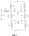
- FIG. 1 is a lumped heat capacity thermal network model of an embodiment of a DSC including the leakage heat flows.
- the leakage thermal resistances R ss and R m are connected to the enclosure temperature T s (not to T 0 ) and a separate sample is included in the network model having temperature T sm and heat capacity C sm .
- the sample is coupled to the sample container by a contact thermal resistance R sm .
- the sample is not needed to perform the heat flow balance and find the sample heat flow, but is included to facilitate the study of heat flow error due to heat leakage.
- the first term is proportional to the difference between the sensor base temperature and the enclosure temperature. It is the difference between the heat that flows through each of the two measuring systems between T 0 and T s .
- the second term represents the difference between the heat stored in the sample and its container and the heat stored in the reference container.
- the third term includes the difference in heat storage between the sample and reference measuring system Of these three terms, only the second includes the sample heat capacity.
- the calibration factor is independent of the sample heat capacity and the measured heat flow rate.
- the first and third terms are not zero. Moreover, they do not include the measured heat flow are and are not proportional to the true heat flow, making the calibration factor dependent on the sample heat capacity, which might introduce errors. To show this, the equation for the measured heat flow can be simplified.
- the first and third terms are assumed to be constant because they include only instrument coefficients, the heating rate b and the temperature difference T s - T s . Assume that the sample and reference container heat capacities are equal and that the resistance ratios in the second term are equal.
- FIG. 1 is a lumped heat capacity thermal network model representing the measuring system with boundary node T 0 that represents the temperature at the base of the DSC sensor that is used to control the measurement assembly temperature, and boundary node T s that represents the enclosure temperature.
- This heat flow rate equation includes a leakage term added to each of the measured sample and reference heat flow rates. These terms are the heat that is exchanged between the sample container and the enclosure and between the reference container and the enclosure. It differs from the equations of the '365. '497 and '595 patents in that the factors multiplying q s and q r do not appear and the temperature differences in the numerators of the leakage terms are T e - T ss and T e - T rr .
- the temperature T 0 shown in the thermal network of FIG. 1 is controlled to follow the desired thermal program, typically comprising constant temperature and constant heating rate segments.
- the desired thermal program typically comprising constant temperature and constant heating rate segments.
- T e heat at the same rate but are offset from one another. T e may lag behind T 0 .
- calorimeter temperatures T s and T r , container temperatures T ss and T rr and sample temperature T sm will also heat at the same heating rate but with different offsets, i.e ., different temperature lags relative to T 0 .
- the leakage thermal resistances R ss and R m are generally much greater than the other thermal resistances within the system.
- Heat will flow from T s through each calorimeter to each of the sample and reference containers. At the same time, heat will be exchanged between each of the sample and reference containers and the enclosure at temperature T s .
- the heat that flows through the sample and reference calorimeters to each of the containers through contact resistances R ss and R rr are the measured heat flow rates q s and q r .
- the total heat that flows to the sample container is the sum of the heat that flows to it through its calorimeter, which is the measured sample heat flow, the heat that flows through its leakage resistance and the heat exchanged between it and the sample.
- the total heat that flows to the reference container is the sum of the heat that flows to it through its calorimeter, which is the measured reference heat flow, and the heat that flows through its leakage resistance.
- the calorimeter thermal resistances and heat capacities must be determined by a calibration method.
- This calibration method uses two identical constant heating rate experiments but uses empty containers in one experiment, and uses containers of the same type with samples of known heat capacity in the second experiment Examples of materials that may be used as samples in the second experiment include sapphire samples having a mass of about 65 mg Typically the same material is used for both samples in the second experiment, with masses that match within a few mg. Other materials may be used in the second experiment, as long as they do not have any transitions in the temperature range of interest, and have a heat capacity that is known with sufficient precision.
- the reason for including containers in these calibration expenments is that the leakage resistances are dependent on whether and what type of containers are present. With this configuration, the same leakage resistances are present in both calibration experiments.
- the calorimeter thermal resistances and heat capacities R s , R r , C s . C r are determined as follows. First heat balance equations are written for temperature nodes T s , T ss , T r and T rr of the thermal model in FIG. 1 for each of the calibration experiments. The heat capacities of the samples are added to those of the container for the experiment that includes samples. Then the pair of equations for T s and T ss are solved for R s and C s in terms of the measured and known quantities and the equations for T r and T rr are solved for R r and C r in terms of the measured and known quantities.
- the measured quantities are: ⁇ T , ⁇ T 0 , T s and T e .
- the known quantities are the heat capacities of the containers and the samples, the thermal contact resistances between the containers and calorimeters and the leakage thermal resistances.
- the subscripts 1 and 2 indicate the first and second of the calibration experiments.
- the sample calorimeter thermal resistance R s , the sample calorimeter heat capacity C s , the reference calorimeter thermal resistance R r , and the reference calorimeter heat capacity C r are given by the following expressions.
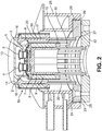
- FIG. 2 is a vertical cross section of an exemplary embodiment taken through the plane intersecting the vertical axes of the sample and reference calorimeters
- heat flow sensor 1 has sample and reference positions 2 and 3. respectively, with sample and reference containers 4 and 5 installed on the sample and reference positions, respectively.
- the sensor assembly may be joined to the measurement heating/cooling assembly 6 by a method such as brazing that ensures a highly reproducible, high thermal conductivity connection between the sensor and the measurement heating/cooling assembly.
- the measurement heating assembly 6 comprises a base structure 7, manufactured from a high thermal conductivity material such as silver, gold, copper or aluminum in the form of a hollow cylinder with one end closed. Platinum alloys or ceramic materials could be used for high temperature measurements
- the heat flow sensor may be attached to the closed end of the base structure and a heating element 8 may be wound on the outer cylindrical surface 9 of the base structure.
- the open end of the base structure may comprise a flange 10 to which may be joined a number of thermal resistors 11 in the form of slender cylindrical rods. The opposite ends of the rods are joined to a cooling flange 12 in the form a flat circular disk with a hole through the center.
- This overall structure provides means for heating and cooling and for regulation of the temperature of the DSC sensor.
- the DSC sensor may be enclosed by the closed-end hollow cylinder 13 that forms the calorimeter enclosure and is essentially uniform in temperature. It is constructed of high thermal conductivity material, for example silver, to maximize its temperature uniformity. It is heated via a relatively thick flange 14 that is integral to the enclosure and is positioned close to the junction of the cylindrical wall and the flat bottom of the cylinder that forms the top of the enclosure. The location of the flange may be chosen to make the maximum temperature differences along the cylindrical wall and across the flat top of the enclosure very nearly the same, thereby minimizing the temperature variation within the enclosure and approaching the isothermal condition as closely as possible.
- flange 14 contacts and exchanges heat with enclosure heating/cooling assembly 15 at flat surface 16.
- Enclosure heating/cooling assembly 15 comprises a high thermal conductivity, typically silver, open ended hollow cylindrical base structure 17.
- Flat top surface 18 supports the enclosure and exchanges heat with it via surface 16 of flange 14 of the enclosure.
- a heating element 19 is wound on the outer cylindrical surface 20 of the base structure.
- the end of the base structure opposite surface 18 comprises a flange 21 to which are joined a number of thermal resistors 22 in the form of slender cylindrical rods.
- the opposite ends of the rods are joined to a cooling flange 23 in the form a flat circular disk with a hole through the center.
- This overall structure provides means for heating, cooling and regulation of the temperature of the DSC enclosure.
- cooling flange 23 of the enclosure heating/cooling assembly has upper heat exchange surface 24 that is the flat top surface of cooling flange 23 and lower heat exchange surface 25 that is the flat bottom surface of cooling flange 23
- Lower heat exchange surface 25 contacts a heat transfer interface material in the form of a thin flat ring 26. It, in turn, contacts heat exchange surface 27 that is the upper flat surface of cooling flange 12 of the measurement heating/cooling assembly.
- Cooling device 28 may be one of a number of devices including the evaporator of a mechanical cooling system, the evaporator of a cooling system using an expendable cryogenic liquid such as liquid nitrogen as exemplified in U.S. Patent No. 6.578.367 . which is incorporated herein by reference; a convection heat exchanger in which a cold fluid like cold water or other liquid flows: an air-cooled heat sink; a thermoelectric cooler, or other types of cooling devices.
- the cooling device is the heat sink for the entire system.
- the numerators of the leakage terms involve temperature differences that will be quite small, much less than 1°C for quasiadiabatic operation. Taking the differences between the values of T a , T ss and T rr to get those temperature differences can introduce significant uncertainty because the temperature differences are taken between large numbers, on the order of hundreds of degrees, to find temperature differences of the order of a few hundredths or thousandths of a degree. This would require that the temperatures T e , T ss and T rr be measured to a very high precision, which is impractical. This can be avoided by substituting the equations given above for T ss and T rr .
- Algebraic equivalents to the above equation i.e ., equations for q that give the same result but may use somewhat different formulations for the factors in the equation, may be used instead of the above equation.
- Other possible expressions could also be used in the equation for heat flow rate, such as T e - T r - ⁇ T or T e - T 0 - ⁇ T 0 . Additional expressions for calculating temperatures and temperature differences are disclosed in the 747 patent. Heat flow rate equations that use any variation of the above equation to calculate the heat flow rate and provide the same result are algebraically equivalent to the equation set forth above
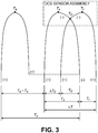
- FIG. 3 is a schematic diagram showing the configuration of the thermocouples used in the exemplary DSC of FIG. 2 . It comprises the DSC sensor thermocouples with the enclosure thermocouple added. Nodes T s , T r and T 0 represent thermocouples junctions that are part of the DSC sensor assemblies described in the 747 and 057 patents. The (+) and (-) signs indicate the polarity of the thermocouple conductors.
- Temperature T 0 is measured between the positive and negative conductors connected to the T 0 junction, the temperature difference ⁇ T 0 measured between the positive conductors connected to the T 0 and T a junctions and the temperature difference ⁇ T is measured between the positive conductors connected to the T s and T r junctions.
- the DSC also includes a thermocouple to measure T e .
- the negative wire of the T e thermocouple is connected to the negative wire of the T 0 thermocouple, facilitating the measurement of temperature difference T e - T s between the positive conductors connected to the T e and T s thermocouple junctions as required in the above heat flow equation. This temperature difference can be readily measured with the requisite precision.
- T s and T r may be measured directly between the positive conductors connected to their respective junctions and the negative conductor connected to the T 0 thermocouple junction, in practice they may be obtained by summing the voltages corresponding to T 0 , ⁇ T 0 and ⁇ T according to the definitions of the temperature differences ⁇ T 0 and ⁇ T.
- Thermocouple junction T e may be attached to the removable cover comprising the DSC enclosure. Its negative conductor is connected to the negative conductor of the T 0 thermocouple allowing the temperature difference T e - T s to be measured between the positive conductors of the T e and T s thermocouples. This method of connecting the four thermocouples allows the temperature differences ⁇ T , ⁇ T 0 and T e - T s to be measured with high precision as required by the heat flow rate measurement while making all temperatures available.
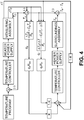
- FIG. 4 is a block diagram of an exemplary temperature control system that may be used in the exemplary embodiment shown in FIG. 2 .
- the temperature program defines the desired trajectory of temperature versus time of the DSC for the desired experiment. It comprises constant temperature segments of defined duration, constant heating/cooling rate segments that typically are defined by terminal temperatures and the rate of change of temperature with respect to time, periodic temperature oscillations for a modulated temperature DSC experiment and other experimental segment types depending upon the material property or phenomenon under investigation and the desired temperature range of the experiment.
- the temperature program is the temperature set point for the measuring assembly temperature control system. It is used to control T 0, the temperature of the base of the DSC sensor.
- the DSC sensor base temperature T 0 is subtracted from the set point temperature to create the temperature error signal which is input to the temperature controller.
- the temperature controller may employ any of a number of well-known control algorithms, for example the well-known proportional plus integral plus derivative algorithm, that operate on the error signal to generate a power command that is input to the heater power supply that supplies the desired electrical current to the heating element of the measuring assembly.
- Output signals from the measuring assembly are T 0 , ⁇ T 0 and ⁇ T , where T 0 is the temperature at the base of the DSC sensor that is used to control the measurement assembly temperature, i.e., it is the temperature of the block of high thermal conductivity material. In operation T 0 is controlled to follow the desired temperature program.
- ⁇ T 0 is T 0 - T s and A T is T s - T r .
- Sample calorimeter temperature T s is obtained by subtracting ⁇ T 0 from T 0
- Measured sample heat flow rate q s is obtained from ⁇ T 0 and T s using the sample heat flow rate measurement equation, while measured reference heat flow rate q, is obtained from ⁇ T 0 , ⁇ T and T s using the reference heat flow rate measurement equation.
- the input for the enclosure temperature control system is the difference between the enclosure temperature T s and a weighted sum of the sample and reference container temperatures T ss and T m i.e., T e - ( KT ss + (1 - K ) T rr ).
- Sample container temperature T ss is multiplied by weighting factor K and reference container temperature T rr is multiplied by weighting factor 1 - K where. 0 ⁇ K ⁇ 1.
- K 0.5
- the input is the difference between the enclosure temperature and the straight average of the sample and reference container temperatures; this input is used during heat flow rate measurement.
- Other values of the weighting factor K may be used if it is advantageous to do so.
- T s - ( KT ss + (1 - K ) T rr ) must be calculated by combining the available inputs. Substituting the equations given above for T ss and T a into the control input equation and collecting terms gives: T a - T s + Kq s R ss + (1 - K ) q r R rr - (1 - K ) ⁇ T which is the input to the temperature controller.
- the instrument uses the temperature difference T e - T s directly as the input to the temperature controller for the enclosure temperature controller.
- the temperature controller may employ any of a number of well, known algorithms, for example proportional plus integral plus derivative, that operate on the error signal to generate a power command that is led to the heater power supply that supplies the desired electrical current to the heating element of the enclosure assembly.
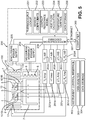
- FIG. 5 is a schematic diagram of an exemplary system for controlling the embodiment of the calorimeter shown in FIG. 2 and for calculating the heat flows and calibration factors
- the DSC comprises three main components: a DSC cell 100.
- DSC cell 100 comprises a heat flow sensor assembly 1 with a sample position 2 and a reference position 3.
- a sample within a sample container 4 and a reference sample within a reference container 5 are placed on the sample and reference positions. In alternative cases, the reference container remains empty.
- Heat is exchanged between each of the containers and its sensor position by a sample thermal contact resistance 101S and a reference thermal contact resistance 101R.
- Sensor assembly 1 is mounted on base structure 7 of the measurement heating assembly 6 which is heated by heating element 8.
- the temperature of the measuring assembly is controlled by heating element 8 which is supplied by measuring assembly power supply 203 In response to temperature control function 235 that is executed in embedded microprocessor 230.
- the output from T e thermocouple analog to digital converter 202a is controlled to match the desired temperature program.
- the enclosure, closed-end hollow cylinder 13. is heated by contact with enclosure heating assembly 15 which comprises high thermal conductivity base structure 17 that is heated by heating element 19 which is supplied by enclosure power supply 205 in response to temperature control function 235 that is executed in embedded microprocessor 230.
- the output from differential thermocouple T e -T s analog to digital convertor 202d is controlled to make the enclosure temperature match the weighted sum ( KT ss + (1 - K ) T rr ) of the sample and reference pan temperatures.
- the measurement and enclosure heating assemblies are coupled to a cooling device.
- DSC module 200 includes T 0 , ⁇ T. ⁇ T0 and T a -T s amplifiers 201a. 201b, 201c and 201d respectively that receive inputs from T a , T s , T r and T s thermocouples as shown and described in FIG. 3 .
- the output from the T 0 , ⁇ T, ⁇ T 0 and T e -T a amplifiers are converted from analog to digital signals by A/D converters 202a, 202b, 202c and 202d
- the output of the A/D convertors is supplied to embedded microprocessor 230.
- Embedded microprocessor comprises thermocouple lookup application 231, sensor coefficient application 232, contact resistance model 233, heat flow calculation 234, temperature control algorithm 235 and data storage function 236.
- Thermocouple Lookup 231 is a program resident in embedded microprocessor 230 that converts the digital signal representing the output signal of the T 0 thermocouple to a temperature.
- the temperature at the terminals of the T 0 thermocouple is measured by a thermistor and that temperature is converted to the equivalent voltage of the thermocouple at that temperature.
- the equivalent thermocouple voltage is summed with the output of the T 0 thermocouple.
- the resultant reference junction compensated voltage is converted to temperature by using a thermocouple lookup table that is based on NIST monograph 175.
- Digital signals representing temperature difference measurements ⁇ T, ⁇ T 0 and T e -T a are converted to temperature units by applying the Seebeck coefficients to the signals representing the voltage at the terminals of the respective temperature differences. Reference junction compensation is not needed when measuring temperature differences.
- the Seeback coefficients are based on NIST monograph 175.
- Sensor Coefficients 232 is a program resident in embedded microprocessor 230 that supplies sensor coefficients R s , R a , C s , C r used in the heat flow calculation.
- the temperature of the DSC cell as indicated by the T 0 thermocouple is used to determine the appropriate value for each of the coefficients.
- Sensor coefficients are determined using the calibration procedures disclosed herein and saved in the module in tabular form.
- the program supplies the sensor coefficients to heat flow calculation program 234.
- Contact Resistance Model 233 is a program resident in embedded microprocessor 230 that calculates the pan contact resistance using the thermal contact resistance model equation disclosed in the 747 patent.
- Heat flow calculator 234 is a program resident in embedded microprocessor 230 that calculates heat flow rates using the methods disclosed herein Sensor coefficients required by the program are supplied by sensor coefficient program 232 and contact resistances needed by the program are supplied by contact thermal resistance model program 233.
- Temperature control 235 is a program resident in embedded microprocessor 230 that determines the power to be supplied to the measurement assembly heater and the power to be supplied to the enclosure assembly heater as shown in FIG. 4 .
- Temperature Control program 235 operates according to a PID (proportional-integral-derivative) control scheme. Power is supplied to the measurement assembly heater to cause the measurement assembly to follow the desired experimental temperature program. Power is supplied to the enclosure heater assembly to cause the enclosure temperature to match a weighted average of sample and reference container temperatures as disclosed herein
- Data storage 236 is nonvolatile storage within the module that stores the data file of the experiment.
- embedded microprocessor 230 is in communication over, e.g., an Ethernet network 30, with computer 300 which comprises instrument control interface module 302, data analysis module 303 and data storage module 304.
- Instrument Control Interface 302 is a program resident in computer 300 that provides the user interface to module 200 it is used to program the thermal method for the experiment, to select any options and to control the instrument, e.g., start and stop experiments, select purge gas flow rates, select instrument mode (for example MDSC or standard DSC), and supply information to autosamplers if applicable.
- Data Analysis 303 is a program resident in computer 300 that is used to display and process the results of the experiment. The user may select the signals to be displayed and display options such as axis scaling and selection of the abscissa. Analysis of the results may also be performed, such as integration of the area of a peak to determine the enthalpy of a transition.
- Data Storage 304 is nonvolatile storage of the data file and the experimental results, e.g., a hard-disk drive or a non-volatile solid-state memory.
Landscapes
- Chemical & Material Sciences (AREA)
- Physics & Mathematics (AREA)
- General Physics & Mathematics (AREA)
- Life Sciences & Earth Sciences (AREA)
- Combustion & Propulsion (AREA)
- Health & Medical Sciences (AREA)
- Analytical Chemistry (AREA)
- Biochemistry (AREA)
- General Health & Medical Sciences (AREA)
- Engineering & Computer Science (AREA)
- Immunology (AREA)
- Pathology (AREA)
- Chemical Kinetics & Catalysis (AREA)
- Investigating Or Analyzing Materials Using Thermal Means (AREA)
Claims (9)
- Verfahren zur Messung eines Differentialwärmeflusses in einem dynamischen Differenzkalorimeter, worin das dynamische Differenzkalorimeter einen Block aus hochwärmeleitfähigem Material innerhalb einer Einhausung umfasst, wobei besagter Block aus hochwärmeleitfähigem Material ein Probenmesssystem und ein Referenzmesssystem umfasst, wobei besagtes Verfahren Folgendes umfasst:Messen einer Temperatur der Einhausung;Kontrollieren der Temperatur des Blocks aus hochwärmeleitfähigem Material gemäß einem vorbestimmten Temperaturprogramm;Messen von T0, ΔT, ΔT0 und Te, wobei T0 die Temperatur des Blocks aus hochwärmeleitfähigem Material ist, ΔT die Differenz zwischen der Temperatur des Probenmesssystems und der Temperatur des Referenzmesssystems ist, ΔT0 die Differenz zwischen der Temperatur des Blocks aus hochwärmeleitfähigem Material und der Temperatur des Probenmesssystems ist und Te die Temperatur der Einhausung ist;Berechnen einer Temperatur eines Probenbehälters (4) im Probenmesssystem und einer Temperatur eines Referenzbehälters im Referenzmesssystem basierend auf den Messwerten von T0, ΔT und ΔT0 ;Kontrollieren der Temperatur der Einhausung, um einem gewichteten Mittelwert der berechneten Temperatur des Probenbehälters (4) und der berechneten Temperatur des Referenzbehälters zu folgen; undBerechnen eines Differentialwärmeflusses zum Probenbehälter (4) mit Bezug auf einen Wärmefluss zum Referenzbehälter basierend auf dem Messen von ΔT, ΔT0, Ts und Te mittels eines Algorithmus, der Korrekturen des gemessenen Wärmeflusses zum Probenbehälter (4) basierend zum Teil auf der Differenz zwischen der Temperatur der Einhausung und der Temperatur des Probenbehälters (4) umfasst.
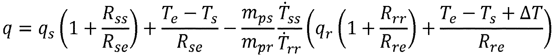
- Verfahren nach Anspruch 1, worin der Schritt des Berechnens eines Differentialwärmeflusses zum Probenbehälter (4) mit Bezug auf den Referenzbehälter die Verwendung einer der folgenden Gleichung und beliebiger anderer zur folgenden Gleichung algebraisch äquivalenter Gleichungen umfasst:
 q ist die Differentialwärmeflussrate zum Probenbehälter (4) mit Bezug auf den Wärmefluss zum Referenzbehälter;qs ist die gemessene Probenwärmeflussrate;qr ist die gemessene Referenzwärmeflussrate;Rss ist der thermische Kontaktwiderstand zwischen dem Probenbehälter (4) und seinem Kalorimeter;Rrr ist der thermische Kontaktwiderstand zwischen dem Referenzbehälter und seinem Kalorimeter;Rse ist der thermische Widerstand zwischen dem Probenbehälter (4) und der Einhausung;Rre ist der thermische Widerstand zwischen dem Referenzbehälter und der Einhausung;Te ist die Temperatur der Einhausung;Ts ist die Temperatur des Probenmesssystems;mps ist die Masse des Probenbehälters (4);mpr ist die Masse des Referenzbehälters;Ṫss ist die Aufheizrate des Probenbehälters (4);Ṫrr ist die Aufheizrate des Referenzbehälters; undΔT ist gleich Ts - Tr, wobei Tr die Temperatur des Referenzmesssystems ist.
 - Verfahren nach Anspruch 1, worin das dynamische Differenzkalorimeter in einem quasiadiabatischen Modus betrieben wird, wodurch Wärmeleckage zwischen dem Proben- und Referenzmesssystem und der Einhausung unterdrückt wird.
- Verfahren nach Anspruch 1, ferner umfassend das Kalibrieren des dynamischen Differenzkalorimeters durch Durchführung eines ersten Experiments bei konstanter Aufheizrate mit leeren Behältern und eines zweiten Experiments bei konstanter Aufheizrate mit der gleichen konstanten Aufheizrate wie beim ersten Experiment mit einer Probe mit bekannter Wärmekapazität im Probenbehälter (4) und einer ähnlichen Probe mit bekannter Wärmeleitfähigkeit im Referenzbehälter.
- Verfahren nach Anspruch 1, worin der gewichtete Mittelwert einen Gewichtungsfaktor verwendet, der größer als oder gleich null und kleiner als oder gleich 1 ist; oder worin der gewichtete Mittelwert der berechneten Temperatur des Probenbehälters (4) und der berechneten Temperatur des Referenzbehälters ein genauer Mittelwert ist.
- Dynamisches Differenzkalorimeter, umfassend:einen Block aus hochwärmeleitfähigem Material umfassend ein Probenmesssystem und ein Referenzmesssystem;eine Einhausung, die den Block aus hochwärmeleitfähigem Material, das Probenmesssystem und das Referenzmesssystem umgreift;ein erstes Thermoelement, das an der Einhausung angebracht ist, zum Messen einer Temperatur der Einhausung Te;ein zweites Thermoelement, das am Block aus hochwärmeleitfähigem Material angebracht ist, zum Messen einer Temperatur des Blocks aus hochwärmeleitfähigem Material T0;ein drittes Thermoelement, das am Probenmesssystem angebracht ist;ein viertes Thermoelement, das am Referenzmesssystem angebracht ist,worin besagte zweite, dritte und vierte Thermoelemente konfiguriert sind, um ΔT0 und ΔT zu messen, wobei ΔT die Differenz zwischen der Temperatur des Probenmesssystems und der Temperatur des Referenzmesssystems ist und wobei ΔT0 die Differenz zwischen der Temperatur des Probenmesssystems und der Temperatur des Blocks aus hochwärmeleitfähigem Material ist;ein Computersystem umfassend ein Modul zum Kontrollieren der Temperatur der Einhausung, ein Modul zum Kontrollieren der Temperatur des Blocks aus hochwärmeleitfähigem Material, ein Modul zum Berechnen eines thermischen Widerstands des Probenmesssystems, einer Wärmekapazität des Probenmesssystems, eines thermischen Widerstands des Referenzmesssystems, einer Wärmekapazität des Referenzmesssystems;wobei das Computersystem Eingaben von den ersten, zweiten, dritten und vierten, für T0, ΔT, ΔT0, und Te repräsentativen Thermoelementen empfängt, wobei T 0 die Temperatur des Blocks aus hochwärmeleitfähigem Material ist, ΔT die Differenz zwischen der Temperatur des Probenmesssystems und der Temperatur des Referenzmesssystems ist, ΔT0 die Differenz zwischen der Temperatur des Blocks aus hochwärmeleitfähigem Material und der Temperatur des Probenmesssystems ist und Te die Temperatur der Einhausung ist,worin das Computersystem dafür programmiert ist, eine Temperatur eines Probenbehälters (4) im Probenmesssystem und eine Temperatur eines Referenzbehälters im Referenzmesssystem basierend auf den Messwerten von T0, ΔT und ΔT0 zu berechnen;worin das Computersystem dafür programmiert ist, die Temperatur der Einhausung zu kontrollieren, um einem gewichteten Mittelwert der berechneten Temperatur des Probenbehälters (4) und der berechneten Temperatur des Referenzbehälters zu folgen; undworin das Computersystem dafür programmiert ist, einen Differentialwärmefluss zum Probenbehälter (4) mit Bezug auf einen Wärmefluss zum Referenzbehälter basierend auf dem Messen von ΔT, ΔT0, Ts und Te mittels eines Algorithmus zu berechnen, der Korrekturen des gemessenen Wärmeflusses zum Probenbehälter (4) basierend zum Teil auf der Differenz zwischen der Temperatur der Einhausung und der Temperatur des Probenbehälters (4) umfasst.
- Dynamisches Differenzkalorimeter nach Anspruch 6, worin das Computersystem einen Differentialwärmefluss zum Probenbehälter (4) mit Bezug auf den Referenzbehälter unter Verwendung einer der folgenden Gleichung und beliebiger anderer zur folgenden Gleichung algebraisch äquivalenter Gleichungen berechnet:
 q ist die Differentialwärmeflussrate zum Probenbehälter (4) mit Bezug auf den Wärmefluss zum Referenzbehälter;qs ist die gemessene Probenwärmeflussrate;qr ist die gemessene Referenzwärmeflussrate;Rss ist der thermische Kontaktwiderstand zwischen dem Probenbehälter (4) und seinem Kalorimeter;Rrr ist der thermische Kontaktwiderstand zwischen dem Referenzbehälter und seinem Kalorimeter;Rse ist der thermische Widerstand zwischen dem Probenbehälter (4) und der Einhausung;Rre ist der thermische Widerstand zwischen dem Referenzbehälter und der Einhausung;Te ist die Temperatur der Einhausung;Ts ist die Temperatur des Probenmesssystems;mps ist die Masse des Probenbehälters (4);mpr ist die Masse des Referenzbehälters;Ṫss ist die Aufheizrate des Probenbehälters (4);Ṫrr ist die Aufheizrate des Referenzbehälters; undΔT ist gleich Ts - Tr, wobei Tr die Temperatur des Referenzmesssystems ist.
 - Verfahren nach Anspruch 1 oder dynamisches Differenzkalorimeter nach Anspruch 6, worin das dynamische Differenzkalorimeter eine Basisstruktur umfassend einen ersten Flansch und einen zweiten Flansch umfasst, ferner umfassend thermische Widerstände in Form von schlanken zylindrischen Stangen, die den ersten Flansch mit dem zweiten Flansch verbinden.
- Dynamisches Differenzkalorimeter nach Anspruch 6, worin die Einhausung ein Hohlzylinder mit geschlossenem Ende (13) mit einem integralen Flansch (14) ist, der in thermischem Kontakt mit einer Heizungs-/Kühlungsanordnung (15) ist, oder worin der Block aus hochwärmeleitfähigem Material ein Block aus einem von Silber, Gold, Aluminium und Kupfer ist.
Applications Claiming Priority (2)
| Application Number | Priority Date | Filing Date | Title |
|---|---|---|---|
| US201261696488P | 2012-09-04 | 2012-09-04 | |
| PCT/US2013/057438 WO2014039376A2 (en) | 2012-09-04 | 2013-08-30 | Quasiadiabatic differential scanning calorimeter |
Publications (3)
| Publication Number | Publication Date |
|---|---|
| EP2893333A2 EP2893333A2 (de) | 2015-07-15 |
| EP2893333A4 EP2893333A4 (de) | 2016-07-06 |
| EP2893333B1 true EP2893333B1 (de) | 2018-01-31 |
Family
ID=50237737
Family Applications (1)
| Application Number | Title | Priority Date | Filing Date |
|---|---|---|---|
| EP13835434.5A Active EP2893333B1 (de) | 2012-09-04 | 2013-08-30 | Quasiadiabatisches dynamisches differenzkalorimeter |
Country Status (3)
| Country | Link |
|---|---|
| US (1) | US9857241B2 (de) |
| EP (1) | EP2893333B1 (de) |
| WO (1) | WO2014039376A2 (de) |
Families Citing this family (10)
| Publication number | Priority date | Publication date | Assignee | Title |
|---|---|---|---|---|
| CN104392139B (zh) * | 2014-11-30 | 2017-04-12 | 西安科技大学 | 基于火灾热释放速率测量的钢结构防火保护设计方法 |
| JP6841425B2 (ja) * | 2017-05-26 | 2021-03-10 | 株式会社リガク | 熱分析装置 |
| CN107300430B (zh) * | 2017-07-18 | 2023-06-16 | 甘肃蓝科石化高新装备股份有限公司 | 一种真空绝热低温管漏热量测量装置及其测量方法 |
| EP3546908B1 (de) | 2018-03-26 | 2021-05-05 | ams International AG | Anordnung und verfahren zum kalibrieren von temperatursensoren |
| CN108459047A (zh) * | 2018-05-23 | 2018-08-28 | 华侨大学 | 新型防火板材导热系数的测量装置及测量方法 |
| US11204289B2 (en) * | 2018-08-23 | 2021-12-21 | Waters Technologies Corporation | Multiple sample differential scanning calorimeter |
| RU195921U1 (ru) * | 2019-12-03 | 2020-02-11 | Антон Леонидович Седнев-Луговец | Высокотемпературный калориметр сброса |
| EP4078161A1 (de) * | 2019-12-20 | 2022-10-26 | TA Instruments-Waters LLC | Wärmeflussratenbestimmung für ein einzelproben-differenz-kalorimeter |
| AT524363B1 (de) * | 2020-10-30 | 2022-06-15 | Anton Paar Gmbh | Messgerät mit elektrothermischem Wandler zum Einstellen eines thermischen Widerstandes, und Betriebsverfahren |
| US20250123160A1 (en) * | 2023-06-08 | 2025-04-17 | OmniCal, Inc. | Heating adiabatic calorimeter and methods of use |
Family Cites Families (12)
| Publication number | Priority date | Publication date | Assignee | Title |
|---|---|---|---|---|
| US5672289A (en) | 1996-01-11 | 1997-09-30 | The Perkin-Elmer Corporation | Heater control circuit |
| JP3137605B2 (ja) * | 1998-07-14 | 2001-02-26 | セイコーインスツルメンツ株式会社 | 熱流束型示差走査熱量計 |
| US6488406B2 (en) | 2000-03-23 | 2002-12-03 | Ta Instruments-Waters, Llc | Differential scanning calorimeter |
| US6431747B1 (en) | 2000-03-23 | 2002-08-13 | Ta Instruments, Inc. | Heat flux differential scanning calorimeter sensor |
| US6561692B2 (en) * | 2000-03-23 | 2003-05-13 | Ta Instruments-Waters Llc | Differential scanning calorimeter |
| US6843595B2 (en) | 2001-01-26 | 2005-01-18 | Waters Investment Limited | Differential scanning calorimeter accounting for heat leakage |
| US6578367B1 (en) | 2001-03-02 | 2003-06-17 | Ta Instruments-Waters Llc | Liquid nitrogen cooling system |
| US7371006B2 (en) * | 2004-02-10 | 2008-05-13 | Perkinelmer Las, Inc. | Differential scanning calorimeter (DSC) with temperature controlled furnace |
| US7470057B2 (en) | 2006-08-24 | 2008-12-30 | Waters Investments Limited | Differential scanning calorimeter sensor and method |
| JP4831487B2 (ja) * | 2006-12-21 | 2011-12-07 | エスアイアイ・ナノテクノロジー株式会社 | 示差走査熱量計 |
| JP5642525B2 (ja) * | 2010-02-02 | 2014-12-17 | 株式会社日立ハイテクサイエンス | 示差走査熱量計 |
| GB201101846D0 (en) | 2011-02-03 | 2011-03-23 | Univ Leuven Kath | Differential adiabatic scanning calorimeter |
-
2013
- 2013-08-30 WO PCT/US2013/057438 patent/WO2014039376A2/en not_active Ceased
- 2013-08-30 EP EP13835434.5A patent/EP2893333B1/de active Active
- 2013-08-30 US US14/425,473 patent/US9857241B2/en active Active
Non-Patent Citations (1)
| Title |
|---|
| None * |
Also Published As
| Publication number | Publication date |
|---|---|
| US20150253206A1 (en) | 2015-09-10 |
| EP2893333A4 (de) | 2016-07-06 |
| WO2014039376A3 (en) | 2014-05-08 |
| WO2014039376A2 (en) | 2014-03-13 |
| EP2893333A2 (de) | 2015-07-15 |
| US9857241B2 (en) | 2018-01-02 |
Similar Documents
| Publication | Publication Date | Title |
|---|---|---|
| EP2893333B1 (de) | Quasiadiabatisches dynamisches differenzkalorimeter | |
| US7470057B2 (en) | Differential scanning calorimeter sensor and method | |
| JP3936847B2 (ja) | 変調差分走査熱量計 | |
| EP2052242B1 (de) | Bestimmung von spezifischer wärmeleistung | |
| Zhuravlev et al. | Fast scanning power compensated differential scanning nano-calorimeter: 1. The device | |
| US8657487B2 (en) | Mini-cell, on-orbit, temperature re-calibration apparatus and method | |
| US8556501B2 (en) | Mini-cell, on-orbit, temperature re-calibration apparatus and method | |
| US11796399B2 (en) | Multiple sample differential scanning calorimeter | |
| US6428203B1 (en) | Power compensation differential scanning calorimeter | |
| JP6042449B2 (ja) | 流体の質量流量を測定する装置および方法 | |
| JP4482281B2 (ja) | 差分走査熱量計における接触熱抵抗を調整するシステムおよび方法 | |
| CN101799439A (zh) | 热分析仪 | |
| Lopeandía et al. | Sensitive power compensated scanning calorimeter for analysis of phase transformations in small samples | |
| US6431747B1 (en) | Heat flux differential scanning calorimeter sensor | |
| JP2004507770A (ja) | 熱量計 | |
| US3813937A (en) | Heat flow calorimeter | |
| US11543373B2 (en) | Heat flow rate determination for a single sample differential scanning calorimeter | |
| Rizzo et al. | Calibration methodology for contact heat flux sensors with enhanced accuracy | |
| Gnanasekaran et al. | Indigenous heat flux differential scanning calorimeter (HF-DSC) | |
| Fletcher et al. | Heat flow calorimeter | |
| Sandu et al. | Differential scanning calorimetric model for corrections to the DSC record | |
| AL-B'ool | A Software Application For The Selection Of Temperature Measuring Sensors Using The Analytic Hierarchy Process (AHP) | |
| JPH08233666A (ja) | 熱電対の温度補正装置 |
Legal Events
| Date | Code | Title | Description |
|---|---|---|---|
| PUAI | Public reference made under article 153(3) epc to a published international application that has entered the european phase |
Free format text: ORIGINAL CODE: 0009012 |
|
| 17P | Request for examination filed |
Effective date: 20150304 |
|
| AK | Designated contracting states |
Kind code of ref document: A2 Designated state(s): AL AT BE BG CH CY CZ DE DK EE ES FI FR GB GR HR HU IE IS IT LI LT LU LV MC MK MT NL NO PL PT RO RS SE SI SK SM TR |
|
| AX | Request for extension of the european patent |
Extension state: BA ME |
|
| DAX | Request for extension of the european patent (deleted) | ||
| A4 | Supplementary search report drawn up and despatched |
Effective date: 20160607 |
|
| RIC1 | Information provided on ipc code assigned before grant |
Ipc: G01N 25/20 20060101AFI20160601BHEP |
|
| GRAP | Despatch of communication of intention to grant a patent |
Free format text: ORIGINAL CODE: EPIDOSNIGR1 |
|
| INTG | Intention to grant announced |
Effective date: 20170802 |
|
| GRAS | Grant fee paid |
Free format text: ORIGINAL CODE: EPIDOSNIGR3 |
|
| GRAA | (expected) grant |
Free format text: ORIGINAL CODE: 0009210 |
|
| AK | Designated contracting states |
Kind code of ref document: B1 Designated state(s): AL AT BE BG CH CY CZ DE DK EE ES FI FR GB GR HR HU IE IS IT LI LT LU LV MC MK MT NL NO PL PT RO RS SE SI SK SM TR |
|
| REG | Reference to a national code |
Ref country code: GB Ref legal event code: FG4D Ref country code: CH Ref legal event code: EP |
|
| REG | Reference to a national code |
Ref country code: AT Ref legal event code: REF Ref document number: 967841 Country of ref document: AT Kind code of ref document: T Effective date: 20180215 |
|
| REG | Reference to a national code |
Ref country code: IE Ref legal event code: FG4D |
|
| REG | Reference to a national code |
Ref country code: DE Ref legal event code: R096 Ref document number: 602013032781 Country of ref document: DE |
|
| REG | Reference to a national code |
Ref country code: NL Ref legal event code: MP Effective date: 20180131 |
|
| REG | Reference to a national code |
Ref country code: LT Ref legal event code: MG4D |
|
| REG | Reference to a national code |
Ref country code: AT Ref legal event code: MK05 Ref document number: 967841 Country of ref document: AT Kind code of ref document: T Effective date: 20180131 |
|
| PG25 | Lapsed in a contracting state [announced via postgrant information from national office to epo] |
Ref country code: FI Free format text: LAPSE BECAUSE OF FAILURE TO SUBMIT A TRANSLATION OF THE DESCRIPTION OR TO PAY THE FEE WITHIN THE PRESCRIBED TIME-LIMIT Effective date: 20180131 Ref country code: NO Free format text: LAPSE BECAUSE OF FAILURE TO SUBMIT A TRANSLATION OF THE DESCRIPTION OR TO PAY THE FEE WITHIN THE PRESCRIBED TIME-LIMIT Effective date: 20180430 Ref country code: HR Free format text: LAPSE BECAUSE OF FAILURE TO SUBMIT A TRANSLATION OF THE DESCRIPTION OR TO PAY THE FEE WITHIN THE PRESCRIBED TIME-LIMIT Effective date: 20180131 Ref country code: NL Free format text: LAPSE BECAUSE OF FAILURE TO SUBMIT A TRANSLATION OF THE DESCRIPTION OR TO PAY THE FEE WITHIN THE PRESCRIBED TIME-LIMIT Effective date: 20180131 Ref country code: ES Free format text: LAPSE BECAUSE OF FAILURE TO SUBMIT A TRANSLATION OF THE DESCRIPTION OR TO PAY THE FEE WITHIN THE PRESCRIBED TIME-LIMIT Effective date: 20180131 Ref country code: LT Free format text: LAPSE BECAUSE OF FAILURE TO SUBMIT A TRANSLATION OF THE DESCRIPTION OR TO PAY THE FEE WITHIN THE PRESCRIBED TIME-LIMIT Effective date: 20180131 |
|
| PG25 | Lapsed in a contracting state [announced via postgrant information from national office to epo] |
Ref country code: RS Free format text: LAPSE BECAUSE OF FAILURE TO SUBMIT A TRANSLATION OF THE DESCRIPTION OR TO PAY THE FEE WITHIN THE PRESCRIBED TIME-LIMIT Effective date: 20180131 Ref country code: PL Free format text: LAPSE BECAUSE OF FAILURE TO SUBMIT A TRANSLATION OF THE DESCRIPTION OR TO PAY THE FEE WITHIN THE PRESCRIBED TIME-LIMIT Effective date: 20180131 Ref country code: IS Free format text: LAPSE BECAUSE OF FAILURE TO SUBMIT A TRANSLATION OF THE DESCRIPTION OR TO PAY THE FEE WITHIN THE PRESCRIBED TIME-LIMIT Effective date: 20180531 Ref country code: BG Free format text: LAPSE BECAUSE OF FAILURE TO SUBMIT A TRANSLATION OF THE DESCRIPTION OR TO PAY THE FEE WITHIN THE PRESCRIBED TIME-LIMIT Effective date: 20180430 Ref country code: SE Free format text: LAPSE BECAUSE OF FAILURE TO SUBMIT A TRANSLATION OF THE DESCRIPTION OR TO PAY THE FEE WITHIN THE PRESCRIBED TIME-LIMIT Effective date: 20180131 Ref country code: LV Free format text: LAPSE BECAUSE OF FAILURE TO SUBMIT A TRANSLATION OF THE DESCRIPTION OR TO PAY THE FEE WITHIN THE PRESCRIBED TIME-LIMIT Effective date: 20180131 Ref country code: AT Free format text: LAPSE BECAUSE OF FAILURE TO SUBMIT A TRANSLATION OF THE DESCRIPTION OR TO PAY THE FEE WITHIN THE PRESCRIBED TIME-LIMIT Effective date: 20180131 Ref country code: GR Free format text: LAPSE BECAUSE OF FAILURE TO SUBMIT A TRANSLATION OF THE DESCRIPTION OR TO PAY THE FEE WITHIN THE PRESCRIBED TIME-LIMIT Effective date: 20180501 |
|
| PG25 | Lapsed in a contracting state [announced via postgrant information from national office to epo] |
Ref country code: EE Free format text: LAPSE BECAUSE OF FAILURE TO SUBMIT A TRANSLATION OF THE DESCRIPTION OR TO PAY THE FEE WITHIN THE PRESCRIBED TIME-LIMIT Effective date: 20180131 Ref country code: IT Free format text: LAPSE BECAUSE OF FAILURE TO SUBMIT A TRANSLATION OF THE DESCRIPTION OR TO PAY THE FEE WITHIN THE PRESCRIBED TIME-LIMIT Effective date: 20180131 Ref country code: AL Free format text: LAPSE BECAUSE OF FAILURE TO SUBMIT A TRANSLATION OF THE DESCRIPTION OR TO PAY THE FEE WITHIN THE PRESCRIBED TIME-LIMIT Effective date: 20180131 Ref country code: RO Free format text: LAPSE BECAUSE OF FAILURE TO SUBMIT A TRANSLATION OF THE DESCRIPTION OR TO PAY THE FEE WITHIN THE PRESCRIBED TIME-LIMIT Effective date: 20180131 |
|
| REG | Reference to a national code |
Ref country code: DE Ref legal event code: R097 Ref document number: 602013032781 Country of ref document: DE |
|
| PG25 | Lapsed in a contracting state [announced via postgrant information from national office to epo] |
Ref country code: CZ Free format text: LAPSE BECAUSE OF FAILURE TO SUBMIT A TRANSLATION OF THE DESCRIPTION OR TO PAY THE FEE WITHIN THE PRESCRIBED TIME-LIMIT Effective date: 20180131 Ref country code: SM Free format text: LAPSE BECAUSE OF FAILURE TO SUBMIT A TRANSLATION OF THE DESCRIPTION OR TO PAY THE FEE WITHIN THE PRESCRIBED TIME-LIMIT Effective date: 20180131 Ref country code: SK Free format text: LAPSE BECAUSE OF FAILURE TO SUBMIT A TRANSLATION OF THE DESCRIPTION OR TO PAY THE FEE WITHIN THE PRESCRIBED TIME-LIMIT Effective date: 20180131 Ref country code: DK Free format text: LAPSE BECAUSE OF FAILURE TO SUBMIT A TRANSLATION OF THE DESCRIPTION OR TO PAY THE FEE WITHIN THE PRESCRIBED TIME-LIMIT Effective date: 20180131 |
|
| PLBE | No opposition filed within time limit |
Free format text: ORIGINAL CODE: 0009261 |
|
| STAA | Information on the status of an ep patent application or granted ep patent |
Free format text: STATUS: NO OPPOSITION FILED WITHIN TIME LIMIT |
|
| 26N | No opposition filed |
Effective date: 20181102 |
|
| PG25 | Lapsed in a contracting state [announced via postgrant information from national office to epo] |
Ref country code: SI Free format text: LAPSE BECAUSE OF FAILURE TO SUBMIT A TRANSLATION OF THE DESCRIPTION OR TO PAY THE FEE WITHIN THE PRESCRIBED TIME-LIMIT Effective date: 20180131 |
|
| PG25 | Lapsed in a contracting state [announced via postgrant information from national office to epo] |
Ref country code: MC Free format text: LAPSE BECAUSE OF FAILURE TO SUBMIT A TRANSLATION OF THE DESCRIPTION OR TO PAY THE FEE WITHIN THE PRESCRIBED TIME-LIMIT Effective date: 20180131 |
|
| REG | Reference to a national code |
Ref country code: CH Ref legal event code: PL |
|
| PG25 | Lapsed in a contracting state [announced via postgrant information from national office to epo] |
Ref country code: LU Free format text: LAPSE BECAUSE OF NON-PAYMENT OF DUE FEES Effective date: 20180830 Ref country code: CH Free format text: LAPSE BECAUSE OF NON-PAYMENT OF DUE FEES Effective date: 20180831 Ref country code: LI Free format text: LAPSE BECAUSE OF NON-PAYMENT OF DUE FEES Effective date: 20180831 |
|
| REG | Reference to a national code |
Ref country code: BE Ref legal event code: MM Effective date: 20180831 |
|
| PG25 | Lapsed in a contracting state [announced via postgrant information from national office to epo] |
Ref country code: BE Free format text: LAPSE BECAUSE OF NON-PAYMENT OF DUE FEES Effective date: 20180831 Ref country code: FR Free format text: LAPSE BECAUSE OF NON-PAYMENT OF DUE FEES Effective date: 20180831 |
|
| PG25 | Lapsed in a contracting state [announced via postgrant information from national office to epo] |
Ref country code: MT Free format text: LAPSE BECAUSE OF NON-PAYMENT OF DUE FEES Effective date: 20180830 |
|
| PG25 | Lapsed in a contracting state [announced via postgrant information from national office to epo] |
Ref country code: TR Free format text: LAPSE BECAUSE OF FAILURE TO SUBMIT A TRANSLATION OF THE DESCRIPTION OR TO PAY THE FEE WITHIN THE PRESCRIBED TIME-LIMIT Effective date: 20180131 |
|
| PG25 | Lapsed in a contracting state [announced via postgrant information from national office to epo] |
Ref country code: PT Free format text: LAPSE BECAUSE OF FAILURE TO SUBMIT A TRANSLATION OF THE DESCRIPTION OR TO PAY THE FEE WITHIN THE PRESCRIBED TIME-LIMIT Effective date: 20180131 |
|
| PG25 | Lapsed in a contracting state [announced via postgrant information from national office to epo] |
Ref country code: CY Free format text: LAPSE BECAUSE OF FAILURE TO SUBMIT A TRANSLATION OF THE DESCRIPTION OR TO PAY THE FEE WITHIN THE PRESCRIBED TIME-LIMIT Effective date: 20180131 Ref country code: IE Free format text: LAPSE BECAUSE OF NON-PAYMENT OF DUE FEES Effective date: 20180830 Ref country code: HU Free format text: LAPSE BECAUSE OF FAILURE TO SUBMIT A TRANSLATION OF THE DESCRIPTION OR TO PAY THE FEE WITHIN THE PRESCRIBED TIME-LIMIT; INVALID AB INITIO Effective date: 20130830 Ref country code: MK Free format text: LAPSE BECAUSE OF NON-PAYMENT OF DUE FEES Effective date: 20180131 |
|
| P01 | Opt-out of the competence of the unified patent court (upc) registered |
Effective date: 20230612 |
|
| PGFP | Annual fee paid to national office [announced via postgrant information from national office to epo] |
Ref country code: DE Payment date: 20250724 Year of fee payment: 13 |
|
| PGFP | Annual fee paid to national office [announced via postgrant information from national office to epo] |
Ref country code: GB Payment date: 20250724 Year of fee payment: 13 |