EP2890932B1 - Method and apparatus for combustion - Google Patents
Method and apparatus for combustion Download PDFInfo
- Publication number
- EP2890932B1 EP2890932B1 EP13832823.2A EP13832823A EP2890932B1 EP 2890932 B1 EP2890932 B1 EP 2890932B1 EP 13832823 A EP13832823 A EP 13832823A EP 2890932 B1 EP2890932 B1 EP 2890932B1
- Authority
- EP
- European Patent Office
- Prior art keywords
- combustion
- fuel
- constriction
- swirler
- plate
- Prior art date
- Legal status (The legal status is an assumption and is not a legal conclusion. Google has not performed a legal analysis and makes no representation as to the accuracy of the status listed.)
- Not-in-force
Links
Images


Classifications
-
- F—MECHANICAL ENGINEERING; LIGHTING; HEATING; WEAPONS; BLASTING
- F23—COMBUSTION APPARATUS; COMBUSTION PROCESSES
- F23D—BURNERS
- F23D11/00—Burners using a direct spraying action of liquid droplets or vaporised liquid into the combustion space
- F23D11/36—Details
- F23D11/38—Nozzles; Cleaning devices therefor
- F23D11/383—Nozzles; Cleaning devices therefor with swirl means
-
- F—MECHANICAL ENGINEERING; LIGHTING; HEATING; WEAPONS; BLASTING
- F23—COMBUSTION APPARATUS; COMBUSTION PROCESSES
- F23C—METHODS OR APPARATUS FOR COMBUSTION USING FLUID FUEL OR SOLID FUEL SUSPENDED IN A CARRIER GAS OR AIR
- F23C6/00—Combustion apparatus characterised by the combination of two or more combustion chambers or combustion zones, e.g. for staged combustion
- F23C6/04—Combustion apparatus characterised by the combination of two or more combustion chambers or combustion zones, e.g. for staged combustion in series connection
-
- F—MECHANICAL ENGINEERING; LIGHTING; HEATING; WEAPONS; BLASTING
- F23—COMBUSTION APPARATUS; COMBUSTION PROCESSES
- F23C—METHODS OR APPARATUS FOR COMBUSTION USING FLUID FUEL OR SOLID FUEL SUSPENDED IN A CARRIER GAS OR AIR
- F23C13/00—Apparatus in which combustion takes place in the presence of catalytic material
-
- F—MECHANICAL ENGINEERING; LIGHTING; HEATING; WEAPONS; BLASTING
- F23—COMBUSTION APPARATUS; COMBUSTION PROCESSES
- F23C—METHODS OR APPARATUS FOR COMBUSTION USING FLUID FUEL OR SOLID FUEL SUSPENDED IN A CARRIER GAS OR AIR
- F23C6/00—Combustion apparatus characterised by the combination of two or more combustion chambers or combustion zones, e.g. for staged combustion
- F23C6/04—Combustion apparatus characterised by the combination of two or more combustion chambers or combustion zones, e.g. for staged combustion in series connection
- F23C6/042—Combustion apparatus characterised by the combination of two or more combustion chambers or combustion zones, e.g. for staged combustion in series connection with fuel supply in stages
-
- F—MECHANICAL ENGINEERING; LIGHTING; HEATING; WEAPONS; BLASTING
- F23—COMBUSTION APPARATUS; COMBUSTION PROCESSES
- F23C—METHODS OR APPARATUS FOR COMBUSTION USING FLUID FUEL OR SOLID FUEL SUSPENDED IN A CARRIER GAS OR AIR
- F23C7/00—Combustion apparatus characterised by arrangements for air supply
- F23C7/002—Combustion apparatus characterised by arrangements for air supply the air being submitted to a rotary or spinning motion
- F23C7/004—Combustion apparatus characterised by arrangements for air supply the air being submitted to a rotary or spinning motion using vanes
-
- F—MECHANICAL ENGINEERING; LIGHTING; HEATING; WEAPONS; BLASTING
- F23—COMBUSTION APPARATUS; COMBUSTION PROCESSES
- F23C—METHODS OR APPARATUS FOR COMBUSTION USING FLUID FUEL OR SOLID FUEL SUSPENDED IN A CARRIER GAS OR AIR
- F23C9/00—Combustion apparatus characterised by arrangements for returning combustion products or flue gases to the combustion chamber
- F23C9/06—Combustion apparatus characterised by arrangements for returning combustion products or flue gases to the combustion chamber for completing combustion
-
- F—MECHANICAL ENGINEERING; LIGHTING; HEATING; WEAPONS; BLASTING
- F23—COMBUSTION APPARATUS; COMBUSTION PROCESSES
- F23D—BURNERS
- F23D11/00—Burners using a direct spraying action of liquid droplets or vaporised liquid into the combustion space
- F23D11/24—Burners using a direct spraying action of liquid droplets or vaporised liquid into the combustion space by pressurisation of the fuel before a nozzle through which it is sprayed by a substantial pressure reduction into a space
-
- F—MECHANICAL ENGINEERING; LIGHTING; HEATING; WEAPONS; BLASTING
- F23—COMBUSTION APPARATUS; COMBUSTION PROCESSES
- F23D—BURNERS
- F23D11/00—Burners using a direct spraying action of liquid droplets or vaporised liquid into the combustion space
- F23D11/36—Details
- F23D11/40—Mixing tubes; Burner heads
- F23D11/402—Mixing chambers downstream of the nozzle
-
- F—MECHANICAL ENGINEERING; LIGHTING; HEATING; WEAPONS; BLASTING
- F23—COMBUSTION APPARATUS; COMBUSTION PROCESSES
- F23D—BURNERS
- F23D11/00—Burners using a direct spraying action of liquid droplets or vaporised liquid into the combustion space
- F23D11/36—Details
- F23D11/42—Starting devices
-
- F—MECHANICAL ENGINEERING; LIGHTING; HEATING; WEAPONS; BLASTING
- F23—COMBUSTION APPARATUS; COMBUSTION PROCESSES
- F23C—METHODS OR APPARATUS FOR COMBUSTION USING FLUID FUEL OR SOLID FUEL SUSPENDED IN A CARRIER GAS OR AIR
- F23C2900/00—Special features of, or arrangements for combustion apparatus using fluid fuels or solid fuels suspended in air; Combustion processes therefor
- F23C2900/03004—Tubular combustion chambers with swirling fuel/air flow
Definitions
- an essentially tube shaped combustion apparatus for providing a homogeneous combustion of liquid fuels, comprises a combustion chamber 1 having a plurality of reaction zones A, B, C, one of which is an injection mixing and evaporation zone A, the other being homogeneous combustion zones for staged homogeneous combustion of evaporated fuel and air.
- a swirler 2 comprising a swirler base 4a and swirler elements 4b, 4c for mixing fuel and air configured to operate at a swirl number between 0.6-2.5 in combination with a flow constriction plate 3 where the size of the constriction is such that the ratio of the open diameter de of the constriction to the diameter d of the tube shaped combustion apparatus 1 is ⁇ 0.7 and the constrictor plate 3 is placed at a distance L1 from the base of the swirler base 4a so that L1/D e > 1.
- a primary mixing plate 7 is placed downstream from the constriction plate 3 at a distance L2 from the constriction plate 3 so that the ratio L2/L1 ⁇ 1 to allow for maximum mixing of the homogeneous combustion process.
- the combustion apparatus uses fuel in the form of any of diesel and gasoline.
- the combustion apparatus comprises a secondary mixing plate, to reduce the total length of the reactor through increased homogenization and/or with a catalyst to operate the process under partial or complete catalytic conditions.
- the combustion apparatus is configured such that in operation the fuel pressure is at an elevated pressure of 3-20 bars to optimize the evaporation in the injection zone.
- the constrictor plate 3 is provided with a truncated cone 9, to improve the recirculation of the combustion products into the injection zone A.
- a method of combustion injecting liquid fuel into a first reaction zone A of a combustion chamber 1, by means of a high pressure nozzle 10 that operates in the region of 3-20 bars of over pressure, mixing the fuel with air that is continuously introduced axially to the combustion chamber 1 by a swirler 2 that produces a swirl strength in the range of 0.6-2.5; igniting the produced fuel/air mixture during start-up of the combustor with a ignition device that initially produces a conventional diffusion flame; forcing the combustion mixture diffusion flame after initial swirl mixing through a radial constriction 3 in the combustion chamber 1.
- the combustion reactor 1, shown in Figure 1 comprises a plurality, suitably three reaction zones A, B and C, in which A is the injection zone where mixing and evaporation takes place, where the fuel is injected into the combustion chamber, mixed with air while undergoing gas phase evaporation.
- Zone A is separated from zone B by a flow constriction plate 3 designed for recirculation of hot combustion products into the injection zone A.
- Zone B and C are homogeneous combustion zones separated by a mixing device 7 for staged homogeneous combustion of evaporated fuel and air.
- the constrictor plate 3 is suitably provided with a cone 9, to improve the recirculation of the combustion products into the injection zone A.
- the liquid fuel is injected into zone A of the combustion chamber 1, by means of a high pressure nozzle 10 that operates in the region of 3-20 bars of over pressure where the fuel is mixed with air that is continuously introduced axially to the combustion chamber 1 by a swirler 2, which may be of the radial or axial type, as shown in Figs. 2a and 2b , that produces a swirl strength in the range of 0.6-2.5.
- a swirler 2 comprises a swirler base 4a, and swirler elements 4b, 4c.
- the swirler elements 4b are provided as “blades” protruding inwards in the combustion chamber at an angle and disposed along a circle concentric with the periphery of the swirler base 4a.
- the swirler elements 4c are provided as "blades" which are located within an inlet portion before entry into the combustion chamber.”
- the produced fuel/air mixture is during start-up of the combustor ignited with a conventional ignition device such as, but not limited to, a glow plug or spark plug that initially produces a conventional diffusion flame.
- a conventional ignition device such as, but not limited to, a glow plug or spark plug that initially produces a conventional diffusion flame.
- the combustion mixture diffusion flame is after initial swirl mixing forced through a radial constriction 3 where the ratio of the open diameter of the radial constriction D e to the tube diameter D is less than 0.7 D e /D ⁇ 0.7 and the distance L1 between the base 4a of the swirler 2 and the constriction plate 3, is such so that ratio of the distance L1 and the constriction open diameter D e is greater than 1 L1/de>1.
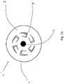
- the radial swirler 2' shown in Fig. 2 comprises a swirler bas plate member 4a with baffle like elements 2a arranged concentrically around a nozzle 6' at a location between the nozzle and the periphery P of the swirler 2.
- baffles 2a are made by punching or cutting out portions in the swirler plate 4a corresponding to circular segments, leaving one portion of the segments attached or integral with the plate 2. This creates foldable "flaps" that can be bent upwards such they project at an angle from the plane of the swirler base plate 4a.
- Fig. 3 shows an axial swirler 2"having a base plate 4a and deflecting elements 2b arranged concentrically around a nozzle 6".
- a negative flow zone is created at the center 5 of the combustion reactor 1 between zone A and B which enables the recirculation of hot combustion products to the fuel injection zone, providing a means for evaporating the fuel in the resulting hot gas mixture.
- a primary mixing plate 7 is placed at a distance L2 from the constriction plate 3 to further increase the mixing of the combustion products and to reduce the risks of hotspot formation.
- the mixing plate 7 is placed at the distance L2 from the constriction plate 3 so that L2/L1 ⁇ 1.
- a secondary mixing plate 8 can be added to the combustor 1 in order to reduce the total length L4 of the combustor 1, by further increasing the total mixing of the homogeneous combustion process.
- Mixing plate 8 can also be replaced by a catalyst to convert the combustor to a catalytic combustor for an optimal emission combustor.
Landscapes
- Engineering & Computer Science (AREA)
- Chemical & Material Sciences (AREA)
- Combustion & Propulsion (AREA)
- Mechanical Engineering (AREA)
- General Engineering & Computer Science (AREA)
- Chemical Kinetics & Catalysis (AREA)
- Pressure-Spray And Ultrasonic-Wave- Spray Burners (AREA)
- Spray-Type Burners (AREA)
Priority Applications (1)
| Application Number | Priority Date | Filing Date | Title |
|---|---|---|---|
| PL13832823T PL2890932T3 (pl) | 2012-08-31 | 2013-08-30 | Sposób i urządzenie do spalania |
Applications Claiming Priority (2)
| Application Number | Priority Date | Filing Date | Title |
|---|---|---|---|
| SE1250973A SE537347C2 (sv) | 2012-08-31 | 2012-08-31 | Apparat för förbränning |
| PCT/SE2013/051021 WO2014035329A1 (en) | 2012-08-31 | 2013-08-30 | Method and apparatus for combustion |
Publications (3)
| Publication Number | Publication Date |
|---|---|
| EP2890932A1 EP2890932A1 (en) | 2015-07-08 |
| EP2890932A4 EP2890932A4 (en) | 2016-03-30 |
| EP2890932B1 true EP2890932B1 (en) | 2017-06-28 |
Family
ID=50183991
Family Applications (1)
| Application Number | Title | Priority Date | Filing Date |
|---|---|---|---|
| EP13832823.2A Not-in-force EP2890932B1 (en) | 2012-08-31 | 2013-08-30 | Method and apparatus for combustion |
Country Status (9)
| Country | Link |
|---|---|
| US (1) | US9857075B2 (pl) |
| EP (1) | EP2890932B1 (pl) |
| JP (1) | JP6329148B2 (pl) |
| CN (1) | CN104822989B (pl) |
| DK (1) | DK2890932T3 (pl) |
| HU (1) | HUE035933T2 (pl) |
| PL (1) | PL2890932T3 (pl) |
| SE (1) | SE537347C2 (pl) |
| WO (1) | WO2014035329A1 (pl) |
Families Citing this family (1)
| Publication number | Priority date | Publication date | Assignee | Title |
|---|---|---|---|---|
| JP6220543B2 (ja) * | 2013-04-15 | 2017-10-25 | バイオマスエナジー株式会社 | バーナー装置及び燃焼炉 |
Family Cites Families (32)
| Publication number | Priority date | Publication date | Assignee | Title |
|---|---|---|---|---|
| US2806517A (en) * | 1950-11-16 | 1957-09-17 | Shell Dev | Oil atomizing double vortex burner |
| US2879836A (en) * | 1957-03-20 | 1959-03-31 | Dumas Albert | Combustion chamber air feeding attachment |
| US3749548A (en) * | 1971-06-28 | 1973-07-31 | Zink Co John | High intensity burner |
| US3886728A (en) * | 1974-05-01 | 1975-06-03 | Gen Motors Corp | Combustor prechamber |
| US4030875A (en) * | 1975-12-22 | 1977-06-21 | General Electric Company | Integrated ceramic-metal combustor |
| US4375949A (en) | 1978-10-03 | 1983-03-08 | Exxon Research And Engineering Co. | Method of at least partially burning a hydrocarbon and/or carbonaceous fuel |
| JPS61134515A (ja) * | 1984-12-03 | 1986-06-21 | Babcock Hitachi Kk | 接触燃焼装置 |
| US4784600A (en) * | 1986-10-08 | 1988-11-15 | Prutech Ii | Low NOx staged combustor with swirl suppression |
| US4706612A (en) * | 1987-02-24 | 1987-11-17 | Prutech Ii | Turbine exhaust fed low NOx staged combustor for TEOR power and steam generation with turbine exhaust bypass to the convection stage |
| IN170251B (pl) * | 1987-04-16 | 1992-03-07 | Luminis Pty Ltd | |
| US4860695A (en) * | 1987-05-01 | 1989-08-29 | Donlee Technologies, Inc. | Cyclone combustion apparatus |
| EP0347834B1 (de) * | 1988-06-21 | 1993-05-12 | Walter Dreizler | Brennerkopf für einen Gebläsegasbrenner |
| US4989549A (en) * | 1988-10-11 | 1991-02-05 | Donlee Technologies, Inc. | Ultra-low NOx combustion apparatus |
| DE3901126A1 (de) * | 1989-01-17 | 1990-07-19 | Elco Oel & Gasbrenner | Brenner zur stoechiometrischen verbrennung von fluessigen oder gasfoermigen brennstoffen |
| US5158445A (en) | 1989-05-22 | 1992-10-27 | Institute Of Gas Technology | Ultra-low pollutant emission combustion method and apparatus |
| US5209187A (en) * | 1991-08-01 | 1993-05-11 | Institute Of Gas Technology | Low pollutant - emission, high efficiency cyclonic burner for firetube boilers and heaters |
| US5131334A (en) * | 1991-10-31 | 1992-07-21 | Monro Richard J | Flame stabilizer for solid fuel burner |
| US5547368A (en) * | 1993-03-01 | 1996-08-20 | Air Products And Chemicals, Inc. | Process and device for combustion-enhanced atomization and vaporization of liquid fuels |
| US5407347A (en) * | 1993-07-16 | 1995-04-18 | Radian Corporation | Apparatus and method for reducing NOx, CO and hydrocarbon emissions when burning gaseous fuels |
| DE4426351B4 (de) * | 1994-07-25 | 2006-04-06 | Alstom | Brennkammer für eine Gasturbine |
| JP2000291910A (ja) * | 1999-04-02 | 2000-10-20 | Toto Ltd | 液体燃料燃焼装置 |
| JP2000356307A (ja) * | 1999-06-16 | 2000-12-26 | Babcock Hitachi Kk | 異種液状燃料用混焼バーナと該バーナを備えた燃焼装置 |
| JP4207356B2 (ja) * | 2000-03-13 | 2009-01-14 | 株式会社サタケ | 燃料噴霧式燃焼バーナ |
| JP3915501B2 (ja) * | 2001-12-11 | 2007-05-16 | 株式会社ノーリツ | 燃焼装置、並びに、湯水加熱装置 |
| FR2853953B1 (fr) * | 2003-04-18 | 2007-02-09 | Air Liquide | Procede de combustion etagee d'un combustible liquide et d'un oxydant dans un four |
| JP4400135B2 (ja) * | 2003-08-01 | 2010-01-20 | トヨタ自動車株式会社 | 燃料改質器用燃焼器 |
| US20050126755A1 (en) * | 2003-10-31 | 2005-06-16 | Berry Jonathan D. | Method and apparatus for improved flame stabilization |
| US7028478B2 (en) * | 2003-12-16 | 2006-04-18 | Advanced Combustion Energy Systems, Inc. | Method and apparatus for the production of energy |
| EP1754003B1 (de) * | 2004-06-08 | 2007-09-19 | Alstom Technology Ltd | Vormischbrenner mit gestufter flüssigbrennstoffversorgung |
| JP2006207890A (ja) * | 2005-01-26 | 2006-08-10 | Miura Co Ltd | 燃焼装置およびボイラ |
| FR2914397B1 (fr) * | 2007-03-26 | 2009-05-01 | Saint Gobain Emballage Sa | Injecteur a jet creux de combustible liquide. |
| US20120064465A1 (en) * | 2010-09-12 | 2012-03-15 | General Vortex Energy, Inc. | Combustion apparatus and methods |
-
2012
- 2012-08-31 SE SE1250973A patent/SE537347C2/sv not_active IP Right Cessation
-
2013
- 2013-08-30 EP EP13832823.2A patent/EP2890932B1/en not_active Not-in-force
- 2013-08-30 DK DK13832823.2T patent/DK2890932T3/en active
- 2013-08-30 WO PCT/SE2013/051021 patent/WO2014035329A1/en not_active Ceased
- 2013-08-30 US US14/424,523 patent/US9857075B2/en not_active Expired - Fee Related
- 2013-08-30 PL PL13832823T patent/PL2890932T3/pl unknown
- 2013-08-30 CN CN201380045345.2A patent/CN104822989B/zh not_active Expired - Fee Related
- 2013-08-30 JP JP2015529754A patent/JP6329148B2/ja not_active Expired - Fee Related
- 2013-08-30 HU HUE13832823A patent/HUE035933T2/en unknown
Non-Patent Citations (1)
| Title |
|---|
| None * |
Also Published As
| Publication number | Publication date |
|---|---|
| WO2014035329A1 (en) | 2014-03-06 |
| PL2890932T3 (pl) | 2017-12-29 |
| DK2890932T3 (en) | 2017-09-18 |
| HUE035933T2 (en) | 2018-05-28 |
| EP2890932A4 (en) | 2016-03-30 |
| SE537347C2 (sv) | 2015-04-07 |
| US9857075B2 (en) | 2018-01-02 |
| JP6329148B2 (ja) | 2018-05-23 |
| EP2890932A1 (en) | 2015-07-08 |
| CN104822989A (zh) | 2015-08-05 |
| JP2015529790A (ja) | 2015-10-08 |
| CN104822989B (zh) | 2018-07-17 |
| US20150260395A1 (en) | 2015-09-17 |
| SE1250973A1 (sv) | 2014-03-01 |
Similar Documents
| Publication | Publication Date | Title |
|---|---|---|
| EP3620719B1 (en) | Gas turbine combustor | |
| EP2244014B1 (en) | Radial lean direct injection burner | |
| EP1193449B1 (en) | Multiple annular swirler | |
| US10480791B2 (en) | Fuel injector to facilitate reduced NOx emissions in a combustor system | |
| EP1985927B1 (en) | Gas turbine combustor system with lean-direct injection for reducing NOx emissions | |
| EP2423600B1 (en) | Gas turbine combustor | |
| JP2713627B2 (ja) | ガスタービン燃焼器、これを備えているガスタービン設備、及びこの燃焼方法 | |
| JP7299424B2 (ja) | さか火現象を防止することができる水素ガス燃焼装置 | |
| EP2722593B1 (en) | Reverse-flow annular combustor for reduced emissions | |
| US6311473B1 (en) | Stable pre-mixer for lean burn composition | |
| EP2754963A1 (en) | Gas turbine combustor | |
| EP1193447B1 (en) | Multiple injector combustor | |
| US20090249789A1 (en) | Burner tube premixer and method for mixing air and gas in a gas turbine engine | |
| US9618198B2 (en) | Burner comprising a reactor for catalytic burning | |
| JP2012037103A (ja) | ガスタービン燃焼器 | |
| KR102096434B1 (ko) | 연소기 | |
| EP2890932B1 (en) | Method and apparatus for combustion | |
| JP2016023916A (ja) | ガスタービン燃焼器 | |
| EP2850365B1 (en) | Catalytic heater and reactor for operating catalytic combustion of liquid fuels | |
| US8495982B2 (en) | Apparatus for mixing fuel and air in a combustion system | |
| CN116951471A (zh) | 燃气涡轮发动机及用于其的混合器组件、燃烧室、雾化燃料的方法 | |
| JP5057363B2 (ja) | ガスタービン燃焼器 | |
| JP2005090884A (ja) | ガスタービン用燃料噴射弁及び低NOx燃焼器 | |
| Khan et al. | Radial lean direct injection burner |
Legal Events
| Date | Code | Title | Description |
|---|---|---|---|
| PUAI | Public reference made under article 153(3) epc to a published international application that has entered the european phase |
Free format text: ORIGINAL CODE: 0009012 |
|
| 17P | Request for examination filed |
Effective date: 20150218 |
|
| AK | Designated contracting states |
Kind code of ref document: A1 Designated state(s): AL AT BE BG CH CY CZ DE DK EE ES FI FR GB GR HR HU IE IS IT LI LT LU LV MC MK MT NL NO PL PT RO RS SE SI SK SM TR |
|
| AX | Request for extension of the european patent |
Extension state: BA ME |
|
| DAX | Request for extension of the european patent (deleted) | ||
| RA4 | Supplementary search report drawn up and despatched (corrected) |
Effective date: 20160302 |
|
| RIC1 | Information provided on ipc code assigned before grant |
Ipc: F23C 7/00 20060101ALI20160225BHEP Ipc: F23R 3/16 20060101ALI20160225BHEP Ipc: F23C 6/04 20060101AFI20160225BHEP Ipc: F23C 9/06 20060101ALI20160225BHEP Ipc: F23R 3/42 20060101ALI20160225BHEP |
|
| GRAP | Despatch of communication of intention to grant a patent |
Free format text: ORIGINAL CODE: EPIDOSNIGR1 |
|
| STAA | Information on the status of an ep patent application or granted ep patent |
Free format text: STATUS: GRANT OF PATENT IS INTENDED |
|
| INTG | Intention to grant announced |
Effective date: 20170317 |
|
| GRAS | Grant fee paid |
Free format text: ORIGINAL CODE: EPIDOSNIGR3 |
|
| GRAA | (expected) grant |
Free format text: ORIGINAL CODE: 0009210 |
|
| STAA | Information on the status of an ep patent application or granted ep patent |
Free format text: STATUS: THE PATENT HAS BEEN GRANTED |
|
| AK | Designated contracting states |
Kind code of ref document: B1 Designated state(s): AL AT BE BG CH CY CZ DE DK EE ES FI FR GB GR HR HU IE IS IT LI LT LU LV MC MK MT NL NO PL PT RO RS SE SI SK SM TR |
|
| REG | Reference to a national code |
Ref country code: GB Ref legal event code: FG4D |
|
| REG | Reference to a national code |
Ref country code: CH Ref legal event code: EP |
|
| REG | Reference to a national code |
Ref country code: AT Ref legal event code: REF Ref document number: 905204 Country of ref document: AT Kind code of ref document: T Effective date: 20170715 |
|
| REG | Reference to a national code |
Ref country code: IE Ref legal event code: FG4D |
|
| REG | Reference to a national code |
Ref country code: DE Ref legal event code: R096 Ref document number: 602013022970 Country of ref document: DE |
|
| REG | Reference to a national code |
Ref country code: FR Ref legal event code: PLFP Year of fee payment: 5 |
|
| REG | Reference to a national code |
Ref country code: DK Ref legal event code: T3 Effective date: 20170913 |
|
| REG | Reference to a national code |
Ref country code: NO Ref legal event code: T2 Effective date: 20170628 |
|
| PG25 | Lapsed in a contracting state [announced via postgrant information from national office to epo] |
Ref country code: GR Free format text: LAPSE BECAUSE OF FAILURE TO SUBMIT A TRANSLATION OF THE DESCRIPTION OR TO PAY THE FEE WITHIN THE PRESCRIBED TIME-LIMIT Effective date: 20170929 Ref country code: HR Free format text: LAPSE BECAUSE OF FAILURE TO SUBMIT A TRANSLATION OF THE DESCRIPTION OR TO PAY THE FEE WITHIN THE PRESCRIBED TIME-LIMIT Effective date: 20170628 Ref country code: FI Free format text: LAPSE BECAUSE OF FAILURE TO SUBMIT A TRANSLATION OF THE DESCRIPTION OR TO PAY THE FEE WITHIN THE PRESCRIBED TIME-LIMIT Effective date: 20170628 Ref country code: LT Free format text: LAPSE BECAUSE OF FAILURE TO SUBMIT A TRANSLATION OF THE DESCRIPTION OR TO PAY THE FEE WITHIN THE PRESCRIBED TIME-LIMIT Effective date: 20170628 |
|
| REG | Reference to a national code |
Ref country code: NL Ref legal event code: MP Effective date: 20170628 |
|
| REG | Reference to a national code |
Ref country code: LT Ref legal event code: MG4D |
|
| REG | Reference to a national code |
Ref country code: AT Ref legal event code: MK05 Ref document number: 905204 Country of ref document: AT Kind code of ref document: T Effective date: 20170628 |
|
| PG25 | Lapsed in a contracting state [announced via postgrant information from national office to epo] |
Ref country code: SE Free format text: LAPSE BECAUSE OF FAILURE TO SUBMIT A TRANSLATION OF THE DESCRIPTION OR TO PAY THE FEE WITHIN THE PRESCRIBED TIME-LIMIT Effective date: 20170628 Ref country code: RS Free format text: LAPSE BECAUSE OF FAILURE TO SUBMIT A TRANSLATION OF THE DESCRIPTION OR TO PAY THE FEE WITHIN THE PRESCRIBED TIME-LIMIT Effective date: 20170628 Ref country code: NL Free format text: LAPSE BECAUSE OF FAILURE TO SUBMIT A TRANSLATION OF THE DESCRIPTION OR TO PAY THE FEE WITHIN THE PRESCRIBED TIME-LIMIT Effective date: 20170628 Ref country code: LV Free format text: LAPSE BECAUSE OF FAILURE TO SUBMIT A TRANSLATION OF THE DESCRIPTION OR TO PAY THE FEE WITHIN THE PRESCRIBED TIME-LIMIT Effective date: 20170628 Ref country code: BG Free format text: LAPSE BECAUSE OF FAILURE TO SUBMIT A TRANSLATION OF THE DESCRIPTION OR TO PAY THE FEE WITHIN THE PRESCRIBED TIME-LIMIT Effective date: 20170928 |
|
| PG25 | Lapsed in a contracting state [announced via postgrant information from national office to epo] |
Ref country code: AT Free format text: LAPSE BECAUSE OF FAILURE TO SUBMIT A TRANSLATION OF THE DESCRIPTION OR TO PAY THE FEE WITHIN THE PRESCRIBED TIME-LIMIT Effective date: 20170628 Ref country code: SK Free format text: LAPSE BECAUSE OF FAILURE TO SUBMIT A TRANSLATION OF THE DESCRIPTION OR TO PAY THE FEE WITHIN THE PRESCRIBED TIME-LIMIT Effective date: 20170628 Ref country code: CZ Free format text: LAPSE BECAUSE OF FAILURE TO SUBMIT A TRANSLATION OF THE DESCRIPTION OR TO PAY THE FEE WITHIN THE PRESCRIBED TIME-LIMIT Effective date: 20170628 Ref country code: RO Free format text: LAPSE BECAUSE OF FAILURE TO SUBMIT A TRANSLATION OF THE DESCRIPTION OR TO PAY THE FEE WITHIN THE PRESCRIBED TIME-LIMIT Effective date: 20170628 Ref country code: EE Free format text: LAPSE BECAUSE OF FAILURE TO SUBMIT A TRANSLATION OF THE DESCRIPTION OR TO PAY THE FEE WITHIN THE PRESCRIBED TIME-LIMIT Effective date: 20170628 |
|
| PG25 | Lapsed in a contracting state [announced via postgrant information from national office to epo] |
Ref country code: SM Free format text: LAPSE BECAUSE OF FAILURE TO SUBMIT A TRANSLATION OF THE DESCRIPTION OR TO PAY THE FEE WITHIN THE PRESCRIBED TIME-LIMIT Effective date: 20170628 Ref country code: IS Free format text: LAPSE BECAUSE OF FAILURE TO SUBMIT A TRANSLATION OF THE DESCRIPTION OR TO PAY THE FEE WITHIN THE PRESCRIBED TIME-LIMIT Effective date: 20171028 Ref country code: ES Free format text: LAPSE BECAUSE OF FAILURE TO SUBMIT A TRANSLATION OF THE DESCRIPTION OR TO PAY THE FEE WITHIN THE PRESCRIBED TIME-LIMIT Effective date: 20170628 |
|
| REG | Reference to a national code |
Ref country code: DE Ref legal event code: R097 Ref document number: 602013022970 Country of ref document: DE |
|
| PG25 | Lapsed in a contracting state [announced via postgrant information from national office to epo] |
Ref country code: MC Free format text: LAPSE BECAUSE OF FAILURE TO SUBMIT A TRANSLATION OF THE DESCRIPTION OR TO PAY THE FEE WITHIN THE PRESCRIBED TIME-LIMIT Effective date: 20170628 |
|
| PLBE | No opposition filed within time limit |
Free format text: ORIGINAL CODE: 0009261 |
|
| GBPC | Gb: european patent ceased through non-payment of renewal fee |
Effective date: 20170928 |
|
| REG | Reference to a national code |
Ref country code: HU Ref legal event code: AG4A Ref document number: E035933 Country of ref document: HU |
|
| REG | Reference to a national code |
Ref country code: IE Ref legal event code: MM4A |
|
| 26N | No opposition filed |
Effective date: 20180329 |
|
| REG | Reference to a national code |
Ref country code: BE Ref legal event code: MM Effective date: 20170831 |
|
| PG25 | Lapsed in a contracting state [announced via postgrant information from national office to epo] |
Ref country code: LU Free format text: LAPSE BECAUSE OF NON-PAYMENT OF DUE FEES Effective date: 20170830 |
|
| PG25 | Lapsed in a contracting state [announced via postgrant information from national office to epo] |
Ref country code: GB Free format text: LAPSE BECAUSE OF NON-PAYMENT OF DUE FEES Effective date: 20170928 Ref country code: IE Free format text: LAPSE BECAUSE OF NON-PAYMENT OF DUE FEES Effective date: 20170830 |
|
| REG | Reference to a national code |
Ref country code: FR Ref legal event code: PLFP Year of fee payment: 6 |
|
| PG25 | Lapsed in a contracting state [announced via postgrant information from national office to epo] |
Ref country code: BE Free format text: LAPSE BECAUSE OF NON-PAYMENT OF DUE FEES Effective date: 20170831 Ref country code: SI Free format text: LAPSE BECAUSE OF FAILURE TO SUBMIT A TRANSLATION OF THE DESCRIPTION OR TO PAY THE FEE WITHIN THE PRESCRIBED TIME-LIMIT Effective date: 20170628 |
|
| PG25 | Lapsed in a contracting state [announced via postgrant information from national office to epo] |
Ref country code: MT Free format text: LAPSE BECAUSE OF NON-PAYMENT OF DUE FEES Effective date: 20170830 |
|
| PG25 | Lapsed in a contracting state [announced via postgrant information from national office to epo] |
Ref country code: CY Free format text: LAPSE BECAUSE OF FAILURE TO SUBMIT A TRANSLATION OF THE DESCRIPTION OR TO PAY THE FEE WITHIN THE PRESCRIBED TIME-LIMIT Effective date: 20170628 |
|
| PGFP | Annual fee paid to national office [announced via postgrant information from national office to epo] |
Ref country code: DK Payment date: 20190920 Year of fee payment: 7 |
|
| PG25 | Lapsed in a contracting state [announced via postgrant information from national office to epo] |
Ref country code: MK Free format text: LAPSE BECAUSE OF FAILURE TO SUBMIT A TRANSLATION OF THE DESCRIPTION OR TO PAY THE FEE WITHIN THE PRESCRIBED TIME-LIMIT Effective date: 20170628 |
|
| PGFP | Annual fee paid to national office [announced via postgrant information from national office to epo] |
Ref country code: HU Payment date: 20190918 Year of fee payment: 7 |
|
| PG25 | Lapsed in a contracting state [announced via postgrant information from national office to epo] |
Ref country code: TR Free format text: LAPSE BECAUSE OF FAILURE TO SUBMIT A TRANSLATION OF THE DESCRIPTION OR TO PAY THE FEE WITHIN THE PRESCRIBED TIME-LIMIT Effective date: 20170628 |
|
| PG25 | Lapsed in a contracting state [announced via postgrant information from national office to epo] |
Ref country code: CH Free format text: LAPSE BECAUSE OF NON-PAYMENT OF DUE FEES Effective date: 20190831 Ref country code: LI Free format text: LAPSE BECAUSE OF NON-PAYMENT OF DUE FEES Effective date: 20190831 Ref country code: PT Free format text: LAPSE BECAUSE OF FAILURE TO SUBMIT A TRANSLATION OF THE DESCRIPTION OR TO PAY THE FEE WITHIN THE PRESCRIBED TIME-LIMIT Effective date: 20170628 |
|
| PG25 | Lapsed in a contracting state [announced via postgrant information from national office to epo] |
Ref country code: AL Free format text: LAPSE BECAUSE OF FAILURE TO SUBMIT A TRANSLATION OF THE DESCRIPTION OR TO PAY THE FEE WITHIN THE PRESCRIBED TIME-LIMIT Effective date: 20170628 |
|
| PG25 | Lapsed in a contracting state [announced via postgrant information from national office to epo] |
Ref country code: IT Free format text: LAPSE BECAUSE OF NON-PAYMENT OF DUE FEES Effective date: 20190830 |
|
| REG | Reference to a national code |
Ref country code: DK Ref legal event code: EBP Effective date: 20200831 |
|
| PG25 | Lapsed in a contracting state [announced via postgrant information from national office to epo] |
Ref country code: HU Free format text: LAPSE BECAUSE OF NON-PAYMENT OF DUE FEES Effective date: 20200831 |
|
| STAA | Information on the status of an ep patent application or granted ep patent |
Free format text: STATUS: NO OPPOSITION FILED WITHIN TIME LIMIT |
|
| PG25 | Lapsed in a contracting state [announced via postgrant information from national office to epo] |
Ref country code: DK Free format text: LAPSE BECAUSE OF NON-PAYMENT OF DUE FEES Effective date: 20200831 |
|
| PGFP | Annual fee paid to national office [announced via postgrant information from national office to epo] |
Ref country code: NO Payment date: 20220715 Year of fee payment: 10 Ref country code: DE Payment date: 20220718 Year of fee payment: 10 |
|
| PGFP | Annual fee paid to national office [announced via postgrant information from national office to epo] |
Ref country code: PL Payment date: 20220708 Year of fee payment: 10 Ref country code: FR Payment date: 20220714 Year of fee payment: 10 |
|
| REG | Reference to a national code |
Ref country code: DE Ref legal event code: R119 Ref document number: 602013022970 Country of ref document: DE |
|
| PG25 | Lapsed in a contracting state [announced via postgrant information from national office to epo] |
Ref country code: NO Free format text: LAPSE BECAUSE OF NON-PAYMENT OF DUE FEES Effective date: 20230831 |
|
| PG25 | Lapsed in a contracting state [announced via postgrant information from national office to epo] |
Ref country code: FR Free format text: LAPSE BECAUSE OF NON-PAYMENT OF DUE FEES Effective date: 20230831 Ref country code: DE Free format text: LAPSE BECAUSE OF NON-PAYMENT OF DUE FEES Effective date: 20240301 |
|
| PG25 | Lapsed in a contracting state [announced via postgrant information from national office to epo] |
Ref country code: PL Free format text: LAPSE BECAUSE OF NON-PAYMENT OF DUE FEES Effective date: 20230830 |
|
| PG25 | Lapsed in a contracting state [announced via postgrant information from national office to epo] |
Ref country code: PL Free format text: LAPSE BECAUSE OF NON-PAYMENT OF DUE FEES Effective date: 20230830 |