EP2890530B1 - Greifvorrichtung - Google Patents
Greifvorrichtung Download PDFInfo
- Publication number
- EP2890530B1 EP2890530B1 EP13750711.7A EP13750711A EP2890530B1 EP 2890530 B1 EP2890530 B1 EP 2890530B1 EP 13750711 A EP13750711 A EP 13750711A EP 2890530 B1 EP2890530 B1 EP 2890530B1
- Authority
- EP
- European Patent Office
- Prior art keywords
- electroadhesive
- section
- gripper
- gripping device
- mounting surface
- Prior art date
- Legal status (The legal status is an assumption and is not a legal conclusion. Google has not performed a legal analysis and makes no representation as to the accuracy of the status listed.)
- Active
Links
Images


Classifications
-
- B—PERFORMING OPERATIONS; TRANSPORTING
- B25—HAND TOOLS; PORTABLE POWER-DRIVEN TOOLS; MANIPULATORS
- B25J—MANIPULATORS; CHAMBERS PROVIDED WITH MANIPULATION DEVICES
- B25J15/00—Gripping heads and other end effectors
- B25J15/0085—Gripping heads and other end effectors with means for applying an electrostatic force on the object to be gripped
-
- B—PERFORMING OPERATIONS; TRANSPORTING
- B25—HAND TOOLS; PORTABLE POWER-DRIVEN TOOLS; MANIPULATORS
- B25J—MANIPULATORS; CHAMBERS PROVIDED WITH MANIPULATION DEVICES
- B25J15/00—Gripping heads and other end effectors
- B25J15/0052—Gripping heads and other end effectors multiple gripper units or multiple end effectors
- B25J15/0066—Gripping heads and other end effectors multiple gripper units or multiple end effectors with different types of end effectors, e.g. gripper and welding gun
-
- B—PERFORMING OPERATIONS; TRANSPORTING
- B25—HAND TOOLS; PORTABLE POWER-DRIVEN TOOLS; MANIPULATORS
- B25J—MANIPULATORS; CHAMBERS PROVIDED WITH MANIPULATION DEVICES
- B25J15/00—Gripping heads and other end effectors
- B25J15/0071—Gripping heads and other end effectors with needles engaging into objects to be gripped
-
- B—PERFORMING OPERATIONS; TRANSPORTING
- B25—HAND TOOLS; PORTABLE POWER-DRIVEN TOOLS; MANIPULATORS
- B25J—MANIPULATORS; CHAMBERS PROVIDED WITH MANIPULATION DEVICES
- B25J15/00—Gripping heads and other end effectors
- B25J15/06—Gripping heads and other end effectors with vacuum or magnetic holding means
-
- B—PERFORMING OPERATIONS; TRANSPORTING
- B65—CONVEYING; PACKING; STORING; HANDLING THIN OR FILAMENTARY MATERIAL
- B65G—TRANSPORT OR STORAGE DEVICES, e.g. CONVEYORS FOR LOADING OR TIPPING, SHOP CONVEYOR SYSTEMS OR PNEUMATIC TUBE CONVEYORS
- B65G47/00—Article or material-handling devices associated with conveyors; Methods employing such devices
- B65G47/74—Feeding, transfer, or discharging devices of particular kinds or types
- B65G47/90—Devices for picking-up and depositing articles or materials
- B65G47/92—Devices for picking-up and depositing articles or materials incorporating electrostatic or magnetic grippers
-
- H—ELECTRICITY
- H10—SEMICONDUCTOR DEVICES; ELECTRIC SOLID-STATE DEVICES NOT OTHERWISE PROVIDED FOR
- H10P—GENERIC PROCESSES OR APPARATUS FOR THE MANUFACTURE OR TREATMENT OF DEVICES COVERED BY CLASS H10
- H10P72/00—Handling or holding of wafers, substrates or devices during manufacture or treatment thereof
- H10P72/70—Handling or holding of wafers, substrates or devices during manufacture or treatment thereof for supporting or gripping
- H10P72/72—Handling or holding of wafers, substrates or devices during manufacture or treatment thereof for supporting or gripping using electrostatic chucks
-
- H—ELECTRICITY
- H10—SEMICONDUCTOR DEVICES; ELECTRIC SOLID-STATE DEVICES NOT OTHERWISE PROVIDED FOR
- H10P—GENERIC PROCESSES OR APPARATUS FOR THE MANUFACTURE OR TREATMENT OF DEVICES COVERED BY CLASS H10
- H10P72/00—Handling or holding of wafers, substrates or devices during manufacture or treatment thereof
- H10P72/70—Handling or holding of wafers, substrates or devices during manufacture or treatment thereof for supporting or gripping
- H10P72/78—Handling or holding of wafers, substrates or devices during manufacture or treatment thereof for supporting or gripping using vacuum or suction, e.g. Bernoulli chucks
Definitions
- the invention relates to a gripping device according to the preamble of claim 1.
- Such gripping devices use the principle of electro-adhesion to exert a holding force on an object to be gripped or held.
- a particularly static electrical potential is applied to at least one electrode of an electroadhesive gripping device.
- an especially static electric field is generated. If the electrodes of such an electroadhesive gripping device are positioned close to the surface of an object to be gripped, an electroadhesive force can be exerted by the gripping device on the object to be gripped via the electric field.
- problems are caused by gripping and holding uneven objects. Due to the short range of Elektroadheskraft it is also problematic to take objects when the electro-adhesive gripping device can not be placed directly on the object to be gripped. An electroadhesive gripping device has so far only a low depth effect. A jump height is difficult to achieve. Therefore, it is also problematic to include a targeted selection or only individual objects from a plurality of juxtaposed objects. In addition, the described gripping devices are only limited to make a separation of objects of a collection of a variety of objects. Finally, the problem can also be the Detachment of a held by the electro-adhesive gripping device object, as it may, for example, in non-conductive objects to an electrostatic charge.
- a multifunction carrier is described in particular for a gripper.
- the multifunction carrier has a planar, serving as a contact surface carrier substrate.
- electrical portions for applying an electroadhesive force to an abutting object.
- flow openings for a Bernoulli suction device and for further vacuum holding devices are provided in the plant level.
- the multi-function carrier is used to fix flat workpieces, such as semiconductor wafers, for their handling, wherein to a certain extent curvatures of the flat workpieces can be compensated.
- the workpiece to be fixed is sucked by means of the Bernoulli suction device with a comparatively large suction force to the contact surface and brought into the sphere of action of the electrodes for the exercise of an electro-adhesion force.
- larger surface irregularities can not be compensated.
- the invention has for its object to provide a gripping device, by means of which also objects with uneven surface contour can be reliably and safely gripped and held.
- a targeted picking up of individual objects or a separation of objects of a collection of different objects should be possible.
- a gripping device having the features of claim 1.
- This comprises a receiving surface, which can be used for gripping an object to be gripped, and at least one electro-adhesion section for exercising an electro-adhesion force on the object.
- the electroadhesion section has at least one electrode for generating an electric field.
- the Elektroadhesionsabites protrudes to rest against the object to be gripped on the receiving surface in the direction of the object to be gripped so that an adjacent to the receiving surface and the Elektroadphasesabrough distance space can be formed.
- the electroadhesion portion is also deformable such that it can be adapted to form when it is to be gripped on the object or on its surface contour.
- the electroadhesion section is in particular designed such that it can be compressed in the direction of the receiving surface when it contacts the object.
- the receiving surface of the gripping device according to the invention need not be formed conformable. Rather, the receiving surface may be rigid, for example, as part of a housing or support portion of the gripping device. This allows a stable and compact construction of the gripping device.
- suction pads for example, have holey surfaces
- the gripping device according to the invention also advantageously allows the integration of additional gripping principles.
- At least one further gripping device functionally independent of the electroadhesion is provided. This is arranged on a distance space limiting portion of the receiving surface.
- a gripping means functionally independent in particular of the electroadhesion is provided or integrated a gripping device for exerting a gripping force in the distance space.
- the gripping means or the gripping device is arranged in the distance space on the receiving surface, or may include these, as explained below by way of example.
- the additional gripping means or gripping means make it possible to exert greater forces with the gripping device according to the invention than would be possible by means of electro-adhesion alone.
- a force can be exerted on the object to be gripped so that it comes into close contact with the electroadhesion section and a deformation of the electroadhesion section for adaptation to the surface structure of the object takes place.
- the elasticity of the electroadhesion section is preferably matched to the holding force that can be exerted with the additional gripping device in the direction of the receiving surface, so that a deformation and adaptation of the electroadhesion section takes place.
- the gripping device can be designed in such a way that, after the article has been received, the article is held exclusively by means of the electro-adhesion force, i. the possible further gripping means or gripping devices are deactivated. This makes it possible to hold the object thus held e.g. to spend in a vacuum environment in which holding by means of negative pressure would no longer be possible. In addition, by deactivating the further gripping device, the energy efficiency can be increased, and yet the workpiece can be held in exact position by means of the electroadhesive gripping device.
- the receiving surface is particularly flat, for example in the manner of a gripper plate of a surface gripper. It is also conceivable, however, a curved course of the receiving surface, for example, as the contact surface of a suction pad.
- an electroadhesive force can be generated according to the principles explained in the introduction.
- the electroadhesive portion is conformable in that it can conform to contours of the surface of the object to be gripped to allow effective initiation of the electroadhesive force.
- the electroadhesion portion is particularly elastic. Preferably, it is formed so soft that a positive connection with portions of the surface of the object to be gripped can be achieved. It is conceivable, for example, an embodiment of an elastomer or a flexible, in particular elastic, foam, for example plastic foam.
- the ElektroadPSsionsabêt is in particular formed like a ridge or like a strip on the receiving surface.
- the deformable electroadhesion section comprises at least one electrode.
- This is in particular self-deformable, for example as a thin metal layer.
- the electrode may also be formed by a carrier material with conductive particles, e.g. Carbon nanotubes, be formed.
- the conductive particles may be introduced into the carrier material or applied to the carrier material.
- the electrode may be incorporated in the electroadhesion section, i. run in its interior. However, it is also conceivable that the electrode runs on a surface of the electroadhesion section facing the object to be gripped. On the electrode, an insulating layer may be applied.
- the further gripping device is designed in particular as a suction gripper, Bernoulli gripper, magnetic gripper, in particular with a controllable magnet, or needle gripper.
- the further gripping device is designed such that a holding force and / or gripping force can be exerted on the object to be gripped in the direction of the receiving surface. This makes it possible to attract objects from a greater distance to the receiving surface. By means of a suitable further gripping device, therefore, a jump height can be achieved. In particular, a Bernoulli gripper can have great depth effect.
- a combination of elektroadphasesiver gripping device and magnetic gripping device with controllable magnet is advantageous for example Handling of metal sheets, especially when cutting them.
- cut sheet metal parts can be selectively removed from the residual grid and pressed by the magnetic force to the Elektroadphasesabêt.
- the magnetic gripping device can be deactivated.
- a needle gripper is used as a further gripping device, a reduced penetration depth of the needles is required due to the additionally acting electroadhesive force, which necessitates, for example, a smaller installation space for the needle gripper.
- Holding the article by means of the electro-adhesion sections advantageously makes it possible to detect whether an article has been picked up by the gripping device. This is based on the effect that the electrical properties of the ElektroadPSsionsabitess can change when an object is applied to it. In particular, it can be detected via the electrical properties of the electroadhesion section, whether a possible additional gripping device of the gripping device has grasped an object and pulls it to the electroadhesion section.
- the at least one electroadhesion section or also the individual electrodes of an electroadhesion section are preferably electrically switched on and off and / or controlled, so that the gripping action can be activated and deactivated or the size of the electroadhesive force can be controlled.
- the gripping device is a device for Controlling the electric potential on the electrodes of the electroadhesive portion.
- different electroadhesion sections and / or different electrodes of an electroadhesion section can be switched on and off independently of each other or electrically controlled.
- the release device is e.g. arranged in the distance space or at a distance space limiting portion of the receiving surface.
- the removal device is provided on the Elektroadphasesabites.
- the detachment force can, for example, be exerted mechanically by means of a displaceable plunger. Preferably, this is in the direction perpendicular to the receiving surface extendable and retractable and arranged in particular in the distance space.
- the detachment can also be done by blowing off.
- the removal device may comprise at least one blow-off opening, which is arranged in particular in the receiving surface, preferably in the distance space.
- the electroadhesive portion may completely enclose the clearance space in directions along the receiving surface, e.g. such that a ring-like or rectangular limited distance space is defined. Thereby, a space sealable by the electroadhesive portion against a surface of the object to be gripped can be provided.
- the ElektroadPSsionsabites not limited the distance space completely.
- a plurality of interlocking ElektroadPSsionsabitese may be provided which extend in particular at an angle on the receiving surface.
- a preferred embodiment of the invention results from the fact that the receiving surface is arranged on a particular elastic absorbent body of a suction pad.
- the absorbent body limits with his Receiving area when attached to the object to be gripped an evacuable suction chamber.
- the absorbent is, for example, bell-shaped.
- the suction chamber is fluidly connected to a vacuum guide, eg a vacuum channel.
- the vacuum guide extends, for example, through the absorbent body in the direction away from the receiving surface and opens, for example, in a vacuum port of the gripping device.
- the electroadhesion section can then be designed as a sealing lip for sealing engagement with an object to be gripped.
- the electroadhesion section may comprise a filling space enclosed by deformable walls.
- the filling space is filled in particular with a granulate, an electrorheological fluid or a magnetorhelical fluid.
- a gas e.g. Air.
- the gripping device may comprise a device to solidify the filling of said filling space.
- a filling space filled with granules can be designed to be evacuable, for which purpose a controllable evacuation device for the filling space can be provided. During evacuation, the air between the granular matter is removed and the filling is thereby solidified.
- a device for introducing an electric or magnetic field into the fluid can be provided. As a result, the electrorheological fluid or the magnetorheological fluid can be solidified in a known manner.
- a comfortable repair or maintenance of the gripping device is made possible in that the at least one electro-adhesion section is arranged on the receiving surface in such a way that it can be fastened and released again.
- an exchange of the electroadhesion portion is possible if, for example, the elastic properties of the material of the electroadhesion section through Change aging.
- the electroadhesion section can be exchanged in a simple manner.
- the gripping device preferably has a plurality of separate Elektroadphasesabitesen, which can be activated and deactivated independently of one another for exerting a Elektroadplisionskraft, that can be acted upon independently of one another with an electrical potential. This allows a targeted recording and a targeted letting go of individual objects.
- the plurality of electro-adhesion portions are arranged such that the receiving surface is divided into a plurality of holding zones.
- Each holding zone is preferably associated with a spacing space which adjoins at least one of the respective holding zone associated Elektroadphasesabêt. With such a gripping device objects can be separated.
- each holding zone has an associated further gripping device as described above.
- the gripping means of the various holding zones are in turn independently activated and deactivated for gripping an object.
- the individual gripping devices are preferably arranged in the respectively assigned distance space, as explained above.
- various cut sheet metal parts can be removed selectively from the residual grid. It is conceivable that the receiving surface is so large that it can be applied when used in a sheet metal cutting machine to a sheet in which a plurality of sheet metal parts is cut out. If the various holding zones and / or the various associated magnetic gripping devices are designed to be activatable and activatable and deactivatable independently of one another, then the sheet metal parts respectively abutting against a holding zone can be gripped and held separately and independently of other sheet metal parts. In the skeleton interior sheet metal parts or Remainders, for example, when cutting a ring, can be separated so specifically from the other parts. With a suitable design of the holding zones can be so very small sheets and sheet metal parts grab and separate.
- each adjacent ElektroadPSsionsabroughe are charged opposite polarity.
- each electroadhesion section may have a plurality of electrodes, which may have different potentials with each other.
- adjacent ElektroadPSsionsabête or adjacent electrodes of ElektroadPSsionsabitese s opposite pole potentials (bipolar or multipolar design).
- a unipolar design is also conceivable, in particular with the same potential.
- a voltage is preferably applied between each adjacent ElektroadPSsionsabbalden a voltage is preferably applied. The voltage can be applied statically over periods of time. However, it is also conceivable to use an alternating voltage.
- the gripping device may be configured such that a controllable current can be passed through at least one electrode of an electroadhesion section.
- the gripping device in particular comprises a current-carrying device, e.g. Wiring for the electrode and a controller with which a controllable power supply can be provided.
- the gripping device can in particular an electronic control device for applying a time-variable potential and for generating a time-varying current flow through at least one electrode of an electro-adhesion section, so that an electromagnetic alternating field can be generated.
- the electrodes can also be designed in such a way that targeted heating of the electrode and of the electroadhesion section can be achieved by means of a controllable current through at least one of the electrodes. This is advantageous when holding held parts or handling should be done in a warm state. This can e.g. be desirable in the handling of semi-finished textile products, where the processing time for processing by melting the binder during handling can be reduced. Said embodiment is also advantageous in the handling of so-called organo sheets, which are deformable only in the heated state (in particular several Kelvin above room temperature), and in which therefore a cooling during the machining process and in particular during handling should be avoided.
- the described gripping devices can be integrated into a gripping system.
- the various gripping devices are then preferably arranged such that the various receiving surfaces lie in an imaginary plane.
- an arrangement of the different receiving surfaces in divergent planes may also be advantageous. It may be advantageous, in particular, if the different gripper devices are arranged to be movable independently of one another.
- FIG. 1 and 2 schematically a gripping device 10 for holding and gripping an object 2 is shown.
- the article 2 has an uneven surface contour.
- the gripping device 10 comprises a receiving surface 12, which is facing this for gripping the article 2.
- the Figures 1 and 2 (as well the FIGS. 3 to 6 ) show the gripping device in a sectional view perpendicular to the receiving surface 12.
- the receiving surface 12 is preferably arranged on a support portion 13 of the gripping device 10. In the illustrated example, the receiving surface 12 is configured just.
- Each electroadhesive portion 14 is formed in a known manner to exert an electroadhesive force on the article 2.
- Each electro-adhesion section 14 comprises at least one electrode 18, by means of which an electrical, in particular electrostatic, field can be generated.
- the electrode 18 is preferably embedded in a portion of the electroadhesive portion 14 facing the article 2. However, it may also be applied to a surface of the electroadhesion section 14 facing in particular the object 2 to be gripped and, for example, covered with an insulating layer.
- Each electro-adhesion section 14 and in particular also the electrode 18 encompassed by it is deformable. As a result, the respective electroadhesion section 14 can adapt to the surface contour of the object 2 when it rests against it, as shown in FIG FIG. 2 is shown.
- the gripping device 10 also has a plurality of further gripping devices 20, which are functionally independent of the Elektroadophsionsabroughen 14.
- the further gripping devices 20 are formed in the example shown as a suction pad 22, which each have a opening into a clearance space 16 in the receiving surface 12 suction opening 23.
- each distance space 16 can serve as the suction space of the respective suction gripper 22, which can be evacuated through the suction opening 23.
- the suction space thus formed can then be sealed by the respective adjacent Elektroadphinsionsabête 14 when they rest against the object to be gripped. 2
- a sealing concern is achieved in particular by the fact that the electroadhesion sections 14 can adapt to the surface contour of the object 2 (cf. FIG. 2 ).
- the object 2 With the gripping device 10, the object 2 can be held reliably and safely.
- the distance between the field-generating electrodes 18 and the object 2 is so small that a large electro-adhesion force is generated.
- the object 2 starting from the in FIG. 1 shown position is first sucked by means of the suction pads 22 in the direction of the receiving surface 12 and comes to rest on the Elektroadscosionsabêten 14.
- the electroadhesive force can then become large enough to hold the article 2 exclusively by means of the electroadhesion portions 14. It is then possible to deactivate the further gripping device 20.
- the electroadhesive force acting between the electroadhesive portions 14 and the article 2 may also serve to achieve a closer fit of the electroadhesive portion 14 to the surface 2 and thus an improved sealing of the spacer space 16 on the surface of the article 2. This makes it possible to exert a large suction force by evacuation of the respective distance space 16 by means of the suction pads 22.
- the Elektroadplisionsabête 14 serve insofar as sealing lips for a suction chamber of a suction pad 22. The actual holding force on the object 2 is then applied not on the Elektroadplisionskraft, but on the negative pressure in the respective distance space 16.
- electroadhesion force in a bipolar embodiment, wherein the receiving surface 12 on the one hand has Elektroadhesionsabête 14, which are connected to a positive electrical potential.
- the in the FIGS. 5 and 6 sketched gripping device 40 is configured substantially in accordance with the gripping devices 10 and 30.
- the different electro-adhesion sections 14 can be activated and deactivated independently of one another for the purpose of exerting an electro-adhesion force.
- the gripping device 40 on an electrical control device, not shown.
- the other gripping means 20 suction pads 22
- the gripping device 40 are also independently activated and deactivated for exerting a gripping force or holding force on the object 2. This makes it possible with the gripping device 40 individual objects of an accumulation of in the FIGS. 5 and 6
- the gripping device 40 can thus be used for singling objects.
- FIG. 7 a gripping device 15 according to the invention designed as a surface gripper is shown in a plan view of the receiving surface 12.
- the gripping device 50 comprises a plurality of separately formed Elektroadphasesabroughen 14, which project beyond the receiving surface 12 in the manner described above.
- the Elektroadphasesabroughe 14 extend partially rectilinearly elongated on the receiving surface 12.
- ElektroadPSsionsabête 14 are provided which extend angled, L-shaped on the receiving surface 12.
- further gripping means 20 are arranged, which e.g. may be formed as suction pads with opening into the receiving surface 12 suction openings 23.
- On the receiving surface 12 a plurality of retaining zones 52 are defined by two L-shaped Elektroadphasesabête 14, which are opposite to another gripping device 20.
- a gripping device 60 according to the invention is again shown in a representation with a view of the receiving surface 12.
- the gripping device 60 has a multiplicity of identically formed, annular Elektroadphasesabête 14 on.
- Each of the annular electro-adhesion sections 14 completely encloses a spacing space 16 in directions along the planar receiving surface 12.
- another gripping device 20 eg suction gripper
- suction gripper is arranged on the receiving surface 12.
- a holding zone 62 is defined on the receiving surface 12.
- the ElektroadPSsionsabitese 14 are arranged in a matrix-like manner on the receiving surface 12 that this is subdivided into holding zones 62 arranged in a matrix.
- the ElektroadPSsionsabitese 14 and the other gripping means 20 for each holding zone 52 and 62 are independently activated and deactivated.
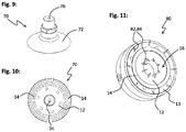
- the gripping device 17 comprises a bell-shaped, flexible absorbent body 72.
- the absorbent body 72 is designed such that it can rest against an object to be gripped and delimits with it a suction chamber which can be evacuated to receive the article.
- the suction space thus formed via a vacuum guide 74 (see FIG. 10 ), which extends through the absorbent body 72, with a vacuum port 76 (see FIG. 9 ) flow connected.
- FIG. 10 shows the gripping device 70 in a view with a view of the receiving surface 12.
- the receiving surface 12 is not flat, but curved like a bell.
- elastically deformable Elektroadhesionsabête 14 are arranged, which protrude beyond the receiving surface 12 in the direction of the object to be gripped. It is particularly advantageous if a Electroadhesion section 14 extends annularly along the radial edge region of the bell-shaped receiving surface 12 of the absorbent body 72. As a result, an improved sealing of the suction chamber can be achieved.
- FIG. 11 shows a gripping device 80.
- This has a plane formed by a rigid support portion 13, flat receiving surface 12. This has openings through which in a conventional manner gripping needles 82 a needle gripping device 84 can be moved beyond the receiving surface 12 out and back again.
- an annular, elastically deformable Elektroadphasesabêt 14 is arranged in the illustrated example. This encloses a distance space 16, in which gripping needles 82 are arranged.
- further movable gripper needles 82 of the needle gripping device 84 are also provided in the region of the receiving surface 12 located radially outside the distance space 16.
Landscapes
- Engineering & Computer Science (AREA)
- Mechanical Engineering (AREA)
- Robotics (AREA)
- Manipulator (AREA)
- Container, Conveyance, Adherence, Positioning, Of Wafer (AREA)
Description
- Die Erfindung betrifft eine Greifvorrichtung nach dem Oberbegriff des Anspruchs 1.
- Derartige Greifvorrichtungen nutzen das Prinzip der Elektroadhäsion, um eine Haltekraft auf einen zu greifenden oder zu haltenden Gegenstand auszuüben. Hierzu wird ein insbesondere statisches elektrisches Potential an wenigstens eine Elektrode einer elektroadhäsiven Greifeinrichtung angelegt. Dadurch wird ein insbesondere statisches elektrisches Feld erzeugt. Werden die Elektroden einer solchen elektroadhäsiven Greifeinrichtung nahe der Oberfläche eines zu greifenden Gegenstandes positioniert, so kann über das elektrische Feld eine Elektroadhäsionskraft von der Greifeinrichtung auf den zu greifenden Gegenstand ausgeübt werden.
- Dabei besteht das Problem, dass der Wirkbereich der Elektroadhäsionskraft um die Elektrode nur eine sehr geringe Größe aufweist. Um einen Gegenstand zuverlässig greifen und halten zu können, darf daher der Abstand zwischen der Oberfläche des zu greifenden Gegenstandes und den Elektroden nur sehr gering sein. Im Stand der Technik sind daher hauptsächlich elektroadhäsive Greifvorrichtungen zur Handhabung von ebenen Bauteilen, beispielsweise Halbleiter-Wafern beschrieben.
- Probleme bereitet insbesondere ein Greifen und Halten von unebenen Objekten. Aufgrund der geringen Reichweite der Elektroadhäsionskraft ist es außerdem problematisch, Gegenstände aufzunehmen, wenn die elektroadhäsive Greifvorrichtung nicht unmittelbar auf den zu greifenden Gegenstand aufgesetzt werden kann. Eine elektroadhäsive Greifvorrichtung weist insofern eine nur geringe Tiefenwirkung auf. Eine Sprunghöhe lässt sich nur schwer erzielen. Daher ist es auch problematisch, aus einer Mehrzahl nebeneinander angeordneter Gegenstände eine gezielte Auswahl oder nur einzelne Gegenstände aufzunehmen. Außerdem sind die beschriebenen Greifvorrichtungen nur begrenzt dazu geeignet, eine Vereinzelung von Gegenständen einer Ansammlung einer Vielzahl von Gegenständen vorzunehmen. Problematisch kann schließlich auch die Ablösung eines von der elektroadhäsiven Greifvorrichtung gehaltenen Objektes sein, da es z.B. bei nicht leitfähigen Gegenständen zu einer elektrostatischen Aufladung kommen kann.
- In der
US 2011/0110010 A1 und derWO 2007/143622 A2 ist eine elektroadhäsive Greifvorrichtung mit den Merkmalen des Oberbegriffs des Anspruchs 1 beschrieben, welche eine sich eben erstreckende, jedoch flexibel verbiegbare Greiffläche aufweist, in welche zur Ausübung einer Elektroadhäsionskraft Elektroabschnitte eingearbeitet sind. - In der
DE 103 19 272 A1 ist ein Multifunktionsträger insbesondere für einen Greifer beschrieben. Der Multifunktionsträger weist ein ebenes, als Anlagefläche dienendes Trägersubstrat auf. In der Ebene des Trägersubstrats sind Elektroabschnitte zum Ausüben einer Elektroadhäsionskraft auf einen anliegenden Gegenstand vorgesehen. Außerdem sind in der Anlageebene Durchströmöffnungen für eine Bernoulli-Saugeinrichtung und für weitere Vakuum-Haltevorrichtungen vorgesehen. Der Multifunktionsträger dient dazu, flächige Werkstücke, wie beispielsweise Halbleiterscheiben, zu ihrer Handhabung zu fixieren, wobei zu einem gewissen Grade Krümmungen der flächigen Werkstücke ausgeglichen werden können. Hierzu wird das zu fixierende Werkstück mittels der Bernoulli-Saugeinrichtung mit einer vergleichsweise großen Saugkraft an die Anlagefläche angesaugt und in den Wirkungsbereich der Elektroden zur Ausübung einer Elektroadhäsionskraft gebracht. Größere Oberflächenunebenheiten können jedoch nicht ausgeglichen werden. - Der Erfindung liegt die Aufgabe zugrunde, eine Greifvorrichtung bereitzustellen, mittels welcher auch Gegenstände mit unebener Oberflächenkontur zuverlässig und sicher gegriffen und gehalten werden können. Insbesondere soll ein gezieltes Aufnehmen einzelner Gegenstände oder eine Vereinzelung von Gegenständen einer Ansammlung verschiedener Gegenstände möglich sein.
- Diese Aufgabe wird durch eine Greifvorrichtung mit den Merkmalen des Anspruchs 1 gelöst. Diese umfasst eine Aufnahmefläche, welche zum Greifen eines zu greifenden Gegenstandes diesem zugewandt werden kann, sowie wenigstens einen Elektroadhäsionsabschnitt zur Ausübung einer Elektroadhäsionskraft auf den Gegenstand. Der Elektroadhäsionsabschnitt weist zumindest eine Elektrode zur Erzeugung eines elektrischen Feldes auf.
- Es ist vorgesehen, dass der Elektroadhäsionsabschnitt zur Anlage an dem zu greifenden Gegenstand über die Aufnahmefläche in Richtung des zu greifenden Gegenstandes derart hervorsteht, dass ein an die Aufnahmefläche und an den Elektroadhäsionsabschnitt angrenzender Abstandsraum gebildet werden kann. Der Elektroadhäsionsabschnitt ist außerdem derart verformbar ausgebildet, dass er bei Anlage an dem zu greifenden Gegenstand beziehungsweise an dessen Oberflächenkontur formanpassbar ist.
- Diese Ausgestaltung ermöglicht es, auch Gegenstände mit Oberflächenstrukturen oder unebene Gegenstände sicher an dem Elektroadhäsionsabschnitt zu halten. Der Elektroadhäsionsabschnitt ist insbesondere derart ausgebildet, dass er bei Anliegen an den Gegenstand in Richtung zur Aufnahmefläche hin komprimierbar ist. Hierzu ist es nicht erforderlich, dass die gesamte Greiffläche als flexibles Bauteil ausgebildet ist, wie dies bei dem eingangs genannten Stand der Technik der Fall ist. Die Aufnahmefläche der erfindungsgemäßen Greifvorrichtung muss nicht formanpassbar ausgebildet sein. Vielmehr kann die Aufnahmefläche starr ausgebildet sein, beispielsweise als Teil eines Gehäuses oder Trägerabschnitt der Greifvorrichtung. Dies ermöglicht einen stabilen und kompakten Aufbau der Greifvorrichtung.
- Dadurch können Gegenstände gehalten werden, welche z.B. aufgrund ihrer Oberflächenbeschaffenheit nicht mit Sauggreifern gehalten werden können (zum Beispiel löchrige Oberflächen aufweisen) oder welche nicht magnetisch ausgebildet sind.
- Die erfindungsgemäße Greifvorrichtung ermöglicht außerdem in vorteilhafter Weise die Integration zusätzlicher Greifprinzipien. Es ist zumindest eine weitere, von der Elektroadhäsion funktional unabhängige Greifeinrichtung vorgesehen. Diese ist an einem den Abstandsraum begrenzenden Abschnitt der Aufnahmefläche angeordnet. Hierzu ist ein insbesondere von der Elektroadhäsion funktional unabhängiges Greifmittel oder eine Greifeinrichtung zur Ausübung einer Greifkraft in den Abstandsraum integriert. Das Greifmittel oder die Greifeinrichtung ist im Abstandsraum an der Aufnahmefläche angeordnet, oder kann diese umfassen, wie nachfolgend noch beispielhaft erläutert. Die zusätzlichen Greifmittel oder Greifeinrichtungen ermöglichen es, mit der erfindungsgemäßen Greifvorrichtung größere Kräfte auszuüben, als dies mittels Elektroadhäsion alleine möglich wäre.
- Ferner kann mit dem zusätzlichen Greifmittel oder der zusätzlichen Greifeinrichtung eine Kraft auf den zu greifenden Gegenstand ausgeübt werden, so dass dieser in engen Kontakt mit dem Elektroadhäsionsabschnitt gelangt und eine Verformung des Elektroadhäsionsabschnitts zur Anpassung an die Oberflächenstruktur des Gegenstandes erfolgt. Die Elastizität des Elektroadhäsionsabschnitts ist vorzugsweise auf die mit der zusätzlichen Greifeinrichtung ausübbare Haltekraft in Richtung der Aufnahmefläche abgestimmt, so dass eine Verformung und Anpassung des Elektroadhäsionsabschnitts erfolgt.
- Wenn der Gegenstand an den Elektroadhäsionsabschnitt anliegt, kann eine große Elektroadhäsionskraft ausgeübt werden. Die Greifvorrichtung kann insbesondere derart ausgestaltet sein, dass nach Aufnahme des Gegenstandes ein Halten des Gegenstandes ausschließlich mittels der Elektroadhäsionskraft erfolgt, d.h. die eventuellen weiteren Greifmittel oder Greifeinrichtungen deaktiviert sind. Dies ermöglicht es, den so gehaltenen Gegenstand z.B. in eine Vakuumumgebung zu verbringen, in welcher ein Halten mittels Unterdruck nicht mehr möglich wäre. Außerdem kann durch eine Deaktivierung der weiteren Greifeinrichtung die Energieeffizienz erhöht werden und dennoch das Werkstück positionsgenau mittels der elektroadhäsiven Greifeinrichtung gehalten werden.
- Die Aufnahmefläche ist insbesondere eben ausgebildet, beispielsweise in der Art einer Greiferplatte eines Flächengreifers. Denkbar ist jedoch auch ein gekrümmter Verlauf der Aufnahmefläche, beispielsweise als Kontaktfläche eines Sauggreifers.
- Mittels des Elektroadhäsionsabschnitts kann nach den eingangs erläuterten Prinzipien eine Elektroadhäsive Kraft erzeugt werden. Der Elektroadhäsionsabschnitt ist formanpassbar insofern, als er sich an Konturen der Oberfläche des zu greifenden Gegenstands anpassen kann, um eine effektive Einleitung der Elektroadhäsionskraft zu ermöglichen. Der Elektroadhäsionsabschnitt ist insbesondere elastisch. Vorzugsweise ist er derart weich ausgebildet, dass ein Formschluss mit Abschnitten der Oberfläche des zu greifenden Gegenstandes erzielt werden kann. Denkbar ist z.B. eine Ausgestaltung aus einem Elastomer oder einem flexiblen, insbesondere elastischen, Schaum, beispielsweise Kunststoffschaum. Der Elektroadhäsionsabschnitt ist insbesondere gratartig oder leistenartig auf der Aufnahmefläche verlaufend ausgebildet.
- Zur Erzeugung des elektrischen Feldes umfasst der verformbare Elektroadhäsionsabschnitt wenigstens eine Elektrode. Diese ist insbesondere selbst verformbar ausgebildet, beispielsweise als dünne Metallschicht. Die Elektrode kann auch durch ein Trägermaterial mit leitenden Partikeln, z.B. Carbon-Nano-Tubes, gebildet sein. Die leitenden Partikel können in das Trägermaterial eingebracht oder auf das Trägermaterial aufgebracht sein. Die Elektrode kann in den Elektroadhäsionsabschnitt eingebracht sein, d.h. in seinem Inneren verlaufen. Denkbar ist jedoch auch, dass die Elektrode auf einer dem zu greifenden Gegenstand zugewandten Oberfläche des Elektroadhäsionsabschnitts verläuft. Auf der Elektrode kann eine Isolierschicht aufgebracht sein.
- Die weitere Greifeinrichtung ist insbesondere als Sauggreifer, Bernoulli-Greifer, Magnetgreifer, insbesondere mit ansteuerbarem Magnet, oder Nadelgreifer ausgebildet. Die weitere Greifeinrichtung ist derart ausgebildet, dass eine Haltekraft und/oder Greifkraft auf den zu greifenden Gegenstand in Richtung der Aufnahmefläche ausgeübt werden kann. Dies ermöglicht es, Gegenstände auch aus größerer Entfernung zur Aufnahmefläche anzuziehen. Mittels einer geeigneten weiteren Greifeinrichtung kann daher eine Sprunghöhe erzielt werden. Insbesondere ein Bernoulli-Greifer kann über große Tiefenwirkung verfügen.
- Eine Kombination von elektroadhäsiver Greifeinrichtung und Magnetgreifeinrichtung mit ansteuerbarem Magnet ist z.B. vorteilhaft zur Handhabung von Blechen, insbesondere bei deren Zuschnitt. Mittels der Magnetgreifeinrichtung können ausgeschnittene Blechteile selektiv aus dem Restgitter entnommen werden und durch die magnetische Kraft an den Elektroadhäsionsabschnitt angedrückt werden. Wenn die elektroadhäsive Haltekraft wirksam ist, kann die Magnetgreifeinrichtung deaktiviert werden.
- Bei Verwendung eines Vakuumgreifers als weitere Greifeinrichtung kann durch die Anpassung der Elektroadhäsionsabschnitte bei Anlage an den Gegenstand eine Leckage reduziert werden. Hierzu ist es besonders vorteilhaft, wenn der Elektroadhäsionsabschnitt derart weich ausgebildet ist, dass ein Formschluss zu Abschnitten der Oberfläche des zu greifenden Gegenstands erzielt werden kann.
- Findet ein Nadelgreifer als weitere Greifeinrichtung Verwendung, so ist aufgrund der zusätzlich wirkenden Elektroadhäsionskraft eine verringerte Eindringtiefe der Nadeln erforderlich, was beispielsweise einen geringeren Bauraum für den Nadelgreifer erforderlich macht.
- Ein Halten des Gegenstandes mittels der Elektroadhäsionsabschnitte ermöglicht in vorteilhafter Weise eine Detektion, ob ein Gegenstand mit der Greifvorrichtung aufgenommen wurde. Dem liegt der Effekt zugrunde, dass sich die elektrischen Eigenschaften des Elektroadhäsionsabschnitts ändern können, wenn ein Gegenstand an ihm anliegt. Insbesondere kann über die elektrischen Eigenschaften des Elektroadhäsionsabschnitts detektiert werden, ob eine eventuelle zusätzliche Greifeinrichtung der Greifvorrichtung einen Gegenstand gegriffen hat und diesen an den Elektroadhäsionsabschnitt zieht.
- Der wenigstens eine Elektroadhäsionsabschnitt oder auch die einzelnen Elektroden eines Elektroadhäsionsabschnitts sind vorzugsweise elektrisch an- und ausschaltbar und/oder ansteuerbar, so dass die Greifwirkung aktivierbar und deaktivierbar ist bzw. die Größe der Elektroadhäsionskraft steuerbar ist. Hierzu kann die Greifvorrichtung eine Einrichtung zur Steuerung des elektrischen Potentials auf den Elektroden des Elektroadhäsionsabschnitts umfassen. Vorzugsweise sind verschiedene Elektroadhäsionsabschnitte und/oder verschiedene Elektroden eines Elektroadhäsionsabschnitts unabhängig voneinander an- und ausschaltbar oder elektrisch ansteuerbar. Diese Ausgestaltungen erlauben ein kontrolliertes Aufnehmen und Loslassen von Gegenständen.
- Es kann auch eine Ablöseeinrichtung zum Ausüben einer Ablösekraft zum Ablösen eines gehaltenen Gegenstandes von dem
- Elektroadhäsionsabschnitt vorgesehen sein. Die Ablöseeinrichtung ist z.B. in dem Abstandsraum oder an einem den Abstandsraum begrenzenden Abschnitt der Aufnahmefläche angeordnet. Denkbar ist jedoch auch, dass die Ablöseeinrichtung an dem Elektroadhäsionsabschnitt vorgesehen ist. Die Ablösekraft kann beispielsweise mechanisch mittels eines verlagerbaren Stößels ausgeübt werden. Vorzugsweise ist dieser in Richtung senkrecht zur Aufnahmefläche aus- und einfahrbar und insbesondere im Abstandsraum angeordnet. Das Ablösen kann jedoch auch durch Abblasen erfolgen. Hierzu kann die Ablöseeinrichtung wenigstens eine Abblasöffnung umfassen, welche insbesondere in der Aufnahmefläche, vorzugsweise in dem Abstandsraum angeordnet ist.
- Der Elektroadhäsionsabschnitt kann den Abstandsraum in Richtungen entlang der Aufnahmefläche vollständig umschließen, z.B. derart, dass ein ringartig oder rechteckig begrenzter Abstandsraum definiert ist. Dadurch kann ein durch den Elektroadhäsionsabschnitt gegen eine Oberfläche des zu greifenden Gegenstands abdichtbarer Abstandsraum bereitgestellt werden.
- Andererseits kann es vorteilhaft sein, wenn der Elektroadhäsionsabschnitt den Abstandsraum nicht vollumfänglich begrenzt. Beispielsweise können mehrere ineinander greifende Elektroadhäsionsabschnitte vorgesehen sein, welche sich insbesondere winkelig auf der Aufnahmefläche erstrecken.
- Eine bevorzugte Ausführungsform der Erfindung ergibt sich dadurch, dass die Aufnahmefläche an einem insbesondere elastischen Saugkörper eines Sauggreifers angeordnet ist. Der Saugkörper begrenzt mit seiner Aufnahmefläche bei Anlage an den zu greifenden Gegenstand einen evakuierbaren Saugraum. Der Saugkörper ist z.B. glockenähnlich ausgebildet. Der Saugraum ist mit einer Unterdruckführung, z.B. einem Vakuumkanal, strömungsverbunden. Die Unterdruckführung erstreckt sich z.B. durch den Saugkörper in die von der Aufnahmefläche abgewandte Richtung und mündet beispielsweise in einen Unterdruckanschluss der Greifvorrichtung.
- Der Elektroadhäsionsabschnitt kann dann als Dichtlippe zur dichtenden Anlage gegen einen zu greifenden Gegenstand ausgebildet sein.
- Um einen an die Oberfläche eines Gegenstands anpassbaren Elektroadhäsionsabschnitt zu realisieren, kann der Elektroadhäsionsabschnitt einen von verformbaren Wandungen umschlossenen Füllraum umfassen. Der Füllraum ist insbesondere mit einem Granulat, einer elektrorheologischen Flüssigkeit oder einer magnetorhelogischen Flüssigkeit befüllt. Denkbar ist jedoch auch eine Befüllung mit einem Gas, z.B. Luft.
- Zur weiteren Ausgestaltung kann die Greifvorrichtung eine Einrichtung aufweisen, um die Füllung des genannten Füllraumes zu verfestigen. Beispielsweise kann ein mit Granulat befüllter Füllraum evakuierbar ausgebildet sein, wozu eine steuerbare Evakuierungseinrichtung für den Füllraum vorgesehen sein kann. Bei Evakuierung wird die Luft zwischen der granularen Materie entfernt und die Füllung dadurch verfestigt. Ist der Füllraum beispielsweise mit einem elektrorheologischen bzw. magnetorheologischen Fluid befüllt, so kann eine Einrichtung zur Einbringung eines elektrischen bzw. magnetischen Feldes in das Fluid vorgesehen sein. Dadurch kann das elektrorheologische Fluid bzw. das magnetorheologische Fluid in bekannter Weise verfestigt werden.
- Eine komfortable Reparatur oder Wartung der Greifvorrichtung wird dadurch ermöglicht, dass der wenigstens eine Elektroadhäsionsabschnitt derart an der Aufnahmefläche angeordnet ist, dass er befestigt und wieder gelöst werden kann. Dadurch ist ein Austausch des Elektroadhäsionsabschnitts möglich, wenn sich z.B. die elastischen Eigenschaften des Materials des Elektroadhäsionsabschnitts durch Alterung verändern. Bei einer Unterbrechung der Kontaktierung der Elektroden oder einzelner Abschnitte kann auf einfache Weise der Elektroadhäsionsabschnitt ausgewechselt werden.
- Die Greifvorrichtung weist vorzugsweise eine Mehrzahl von separaten Elektroadhäsionsabschnitten auf, welche unabhängig voneinander zur Ausübung einer Elektroadhäsionskraft aktivierbar und deaktivierbar sind, das heißt unabhängig voneinander mit einem elektrischen Potential beaufschlagt werden können. Dies ermöglicht eine gezielte Aufnahme und ein gezieltes Loslassen einzelner Gegenstände.
- Vorzugsweise sind die mehreren Elektroadhäsionsabschnitte derart angeordnet, dass die Aufnahmefläche in mehrere Haltezonen unterteilt ist. Jeder Haltezone ist dabei vorzugsweise ein Abstandsraum zugeordnet, welcher an wenigstens einen der jeweiligen Haltezone zugeordneten Elektroadhäsionsabschnitt angrenzt. Mit einer derartigen Greifvorrichtung können Gegenstände vereinzelt werden. Vorzugsweise weist jede Haltezonen eine zugeordnete weitere Greifeinrichtung wie oben beschrieben auf. Vorzugsweise sind die Greifeinrichtungen der verschiedenen Haltezonen wiederum unabhängig voneinander zum Greifen eines Gegenstandes aktivierbar und deaktivierbar. Die einzelnen Greifeinrichtungen sind vorzugsweise in dem jeweils zugeordneten Abstandsraum angeordnet, wie vorstehend erläutert.
- Sind z.B. verschiedenen Abstandsräumen verschiedene, insbesondere unabhängig ansteuerbare, Magnetgreifeinrichtungen zugeordnet, so können z.B. verschiedene ausgeschnittene Blechteile selektiv aus dem Restgitter entnommen werden. Denkbar ist, dass die Aufnahmefläche so groß ist, dass sie beim Einsatz in einer Blechschneideanlage an ein Blech anlegbar ist, in welchem eine Mehrzahl von Blechteilen ausgeschnitten ist. Wenn die verschiedenen Haltezonen und/oder die verschiedenen zugeordneten Magnetgreifeinrichtungen unabhängig voneinander ansteuerbar bzw. aktivierbar und deaktivierbar ausgebildet sind, dann können die jeweils an einer Haltezone anliegenden Blechteile gezielt und unabhängig von anderen Blechteilen gegriffen, gehalten und separat abgelegt werden. In dem Restgitter innenliegende Blechteile oder Reststücke, die z.B. beim Schneiden eines Ringes entstehen, können so gezielt von den übrigen Teilen getrennt werden. Bei geeigneter Ausgestaltung der Haltezonen lassen sich so auch sehr kleine Bleche und Blechteile greifen und vereinzeln.
- Bei sämtlichen Ausgestaltungen der erfindungsgemäßen Greifvorrichtung können verschiedene Elektroadhäsionsabschnitte mit voneinander abweichenden, elektrischen Potentialen belegt werden. Denkbar ist insbesondere, dass jeweils benachbarte Elektroadhäsionsabschnitte gegenpolig aufgeladen sind. Insbesondere kann jeder Elektroadhäsionsabschnitt eine Mehrzahl von Elektroden aufweisen, welche untereinander verschiedene Potentiale aufweisen können. Vorzugsweise weisen benachbarte Elektroadhäsionsabschnitte oder benachbarte Elektroden eines Elektroadhäsionsabschnittes gegenpolige Potentiale auf (bipolare oder multipolare Ausgestaltung). Denkbar ist jedoch auch eine unipolare Ausgestaltung, insbesondere mit gleichem Potential. Zwischen jeweils benachbarten Elektroadhäsionsabschnitten wird vorzugsweise eine Spannung angelegt. Die Spannung kann über Zeitabschnitte jeweils statisch angelegt werden. Denkbar ist jedoch auch die Verwendung einer alternierenden Spannung.
- Zur weiteren Ausgestaltung kann die Greifvorrichtung derart ausgestaltet sein, dass durch wenigstens eine Elektrode eines Elektroadhäsionsabschnitts ein steuerbarer Strom geleitet werden kann. Hierzu weist die Greifvorrichtung insbesondere eine Stromführungseinrichtung auf, z.B. Verdrahtung für die Elektrode und ein Steuergerät, mit dem eine steuerbare Stromversorgung bereitgestellt werden kann.
- Dadurch kann ein Magnetfeld variierbarer Größe und Polung erzielt werden. Dies kann dazu dienen, eine ergänzende Haltekraft beispielsweise auf magnetische oder magnetisierbare Gegenstände auszuüben. Umgekehrt kann das variierbare Magnetfeld dazu eingesetzt werden, einen magnetischen Gegenstand gezielt abzustoßen und so ein Ablösen von den Elektroadhäsionsabschnitten zu erzielen. Die Greifvorrichtung kann insbesondere eine elektronische Steuereinrichtung zum Anlegen eines zeitlich veränderlichen Potentials und zur Erzeugung eines zeitlich veränderlichen Stromflusses durch wenigstens eine Elektrode eines Elektroadhäsionsabschnitts aufweisen, so dass ein elektromagnetisches Wechselfeld erzeugt werden kann.
- Die Elektroden können auch derart ausgebildet sein, dass mittels eines steuerbaren Stroms durch wenigstens eine der Elektroden eine gezielte Erwärmung der Elektrode und des Elektroadhäsionsabschnitts erzielt werden kann. Dies ist vorteilhaft, wenn gehaltene Teile erwärmt werden sollen oder eine Handhabung in warmem Zustand erfolgen soll. Dies kann z.B. bei der Handhabung von textilen Halbzeugen erwünscht sein, wo die Prozesszeit für Bearbeitungen durch Aufschmelzen des Binders während der Handhabung verringert werden kann. Die genannte Ausgestaltung ist auch vorteilhaft bei der Handhabung von sogenannten Organoblechen, welche nur in erwärmten Zustand (insbesondere mehrere Kelvin über Raumtemperatur) verformbar sind, und bei denen daher eine Abkühlung während des Bearbeitungsprozesses und insbesondere während der Handhabung vermieden werden soll.
- Zur Lösung der eingangs gestellten Aufgabe können auch mehrere der beschriebenen Greifvorrichtungen in ein Greifsystem integriert werden. Die verschiedenen Greifvorrichtungen sind dann vorzugsweise derart angeordnet, dass die verschiedenen Aufnahmeflächen in einer gedachten Ebene liegen. Um ein flexibles Greifen zu ermöglichen, kann jedoch auch eine Anordnung der verschiedenen Aufnahmeflächen in voneinander abweichenden Ebenen vorteilhaft sein. Vorteilhaft kann es insbesondere sein, wenn die verschiedenen Greifvorrichtungen voneinander unabhängig bewegbar angeordnet sind.
- Weitere Einzelheiten und vorteilhafte Ausgestaltungen der Erfindung sind der nachfolgenden Beschreibung zu entnehmen, anhand derer die in den Figuren dargestellten Ausführungsformen der Erfindung näher beschrieben und erläutert sind.
- Es zeigen:
-
Fig. 1 und -
Fig. 2 Skizzen zur Erläuterung einer ersten erfindungsgemäßen Greifvorrichtung in unipolarer Ausgestaltung; -
Fig. 3 und -
Fig. 4 Skizzen zur Erläuterung einer weiteren erfindungsgemäßen Greifvorrichtung in bipolarer Ausführung; -
Fig. 5 und -
Figur 6 Skizzen zur Erläuterung einer wiederum weiteren Ausführungsform zur Vereinzelung von Gegenständen; -
Figur 7 eine erfindungsgemäße Greifvorrichtung; -
Figur 8 eine weitere Ausführungsform einer erfindungsgemäßen Greifvorrichtung; -
Fig. 9 und -
Figur 10 eine erfindungsgemäße Greifvorrichtung mit Sauggreifer; -
Figur 11 eine erfindungsgemäße Greifvorrichtung mit Nadelgreifer. - In der nachfolgenden Beschreibung sind für gleiche oder einander entsprechende Bauteile dieselben Bezugszeichen verwendet. In den
Figuren 1 und 2 ist schematisch eine Greifvorrichtung 10 zum Halten und Greifen eines Gegenstands 2 dargestellt. Der Gegenstand 2 weist eine unebene Oberflächenkontur auf. - Die Greifvorrichtung 10 umfasst eine Aufnahmefläche 12, welche zum Greifen des Gegenstands 2 diesem zugewandt wird. Die
Figuren 1 und 2 (ebenso dieFiguren 3 bis 6 ) zeigen die Greifvorrichtung in einer Schnittdarstellung senkrecht zur Aufnahmefläche 12. Die Aufnahmefläche 12 ist vorzugsweise an einem Trägerabschnitt 13 der Greifvorrichtung 10 angeordnet. Im dargestellten Beispiel ist die Aufnahmefläche 12 eben ausgestaltet. - An der Aufnahmefläche 12 sind mehrere Elektroadhäsionsabschnitte 14 vorgesehen. Diese dienen zur Anlage an den zu greifenden Gegenstand 2 und stehen über die Aufnahmefläche 12 in Richtung des zu greifenden Gegenstands 2 derart hervor, dass jeweils ein von einem Abschnitt der Aufnahmefläche 12 und wenigstens einem Elektroadhäsionsabschnitt 14 begrenzter Abstandsraum 16 gebildet wird.
- Jeder Elektroadhäsionsabschnitt 14 ist in bekannter Weise zur Ausübung einer Elektroadhäsionskraft auf dem Gegenstand 2 ausgebildet. Hierzu umfasst jeder Elektroadhäsionsabschnitt 14 zumindest eine Elektrode 18, mittels welcher ein elektrisches, insbesondere elektrostatisches Feld, erzeugt werden kann. Die Elektrode 18 ist vorzugsweise in einem dem Gegenstand 2 zugewandten Abschnitt des Elektroadhäsionsabschnitts 14 eingebettet. Sie kann jedoch auch auf eine insbesondere dem zu greifenden Gegenstand 2 zugewandte Oberfläche des Elektroadhäsionsabschnitts 14 aufgebracht sein und beispielsweise mit einer Isolierschicht bedeckt sein.
- Jeder Elektroadhäsionsabschnitt 14 und insbesondere auch die von diesem umfasste Elektrode 18 ist verformbar ausgebildet. Dadurch kann sich der jeweilige Elektroadhäsionsabschnitt 14 bei Anlage an den Gegenstand 2 an dessen Oberflächenkontur anpassen, wie dies in
Figur 2 dargestellt ist. - Die Greifvorrichtung 10 weist außerdem eine Mehrzahl von weiteren Greifeinrichtungen 20 auf, welche funktional von den Elektroadhäsionsabschnitten 14 unabhängig sind. Die weiteren Greifeinrichtungen 20 sind im dargestellten Beispiel als Sauggreifer 22 ausgebildet, welche jeweils eine in einen Abstandsraum 16 in der Aufnahmefläche 12 mündende Saugöffnung 23 aufweisen. Bei geeigneter Ausgestaltung der Elektroadhäsionsabschnitte 14 kann daher jeder Abstandsraum 16 als Saugraum des jeweiligen Sauggreifers 22 dienen, welcher durch die Saugöffnung 23 evakuierbar ist. Der so gebildete Saugraum kann dann durch die jeweils angrenzenden Elektroadhäsionsabschnitte 14 abgedichtet werden, wenn diese an dem zu greifenden Gegenstand 2 anliegen. Ein dichtendes Anliegen wird insbesondere dadurch erreicht, dass sich die Elektroadhäsionsabschnitte 14 der Oberflächenkontur des Gegenstands 2 anpassen können (vergleiche
Figur 2 ). - Mit der Greifvorrichtung 10 kann der Gegenstand 2 zuverlässig und sicher gehalten werden. Einerseits ist es möglich, die Greifvorrichtung 10 dem Gegenstand 2 anzunähern und die Aufnahmefläche 12 derart in Richtung des Gegenstands 2 zu drücken, dass die Elektroadhäsionsabschnitte 14 an dem Gegenstand 2 anliegen und sich durch Verformung an die Oberflächenkontur des Gegenstands 2 anpassen. Dadurch ist der Abstand zwischen den felderzeugenden Elektroden 18 und dem Gegenstand 2 so gering, dass eine große Elektroadhäsionskraft erzeugt wird.
- Es ist jedoch auch möglich, dass der Gegenstand 2 ausgehend von der in
Figur 1 dargestellten Lage zunächst mittels der Sauggreifer 22 in Richtung der Aufnahmefläche 12 angesaugt wird und an den Elektroadhäsionsabschnitten 14 zum Anliegen kommt. Durch das Anliegen an den Elektroadhäsionsabschnitten 14 und die mögliche Formanpassung der Elektroadhäsionsabschnitte 14 an die Oberfläche des Gegenstands 2 kann dann die Elektroadhäsionskraft groß genug werden, um den Gegenstand 2 ausschließlich mittels der Elektroadhäsionsabschnitte 14 zu halten. Es ist dann möglich, die weitere Greifeinrichtung 20 zu deaktivieren. - Die zwischen den Elektroadhäsionsabschnitten 14 und dem Gegenstand 2 wirkende Elektroadhäsionskraft kann auch dazu dienen, eine engere Anlage des Elektroadhäsionsabschnitts 14 an die Oberfläche 2 und damit eine verbesserte Abdichtung des Abstandsraumes 16 an der Oberfläche des Gegenstands 2 zu erzielen. Dies ermöglicht es, mittels der Sauggreifer 22 eine große Saugkraft durch Evakuierung des jeweiligen Abstandsraums 16 auszuüben. Die Elektroadhäsionsabschnitte 14 dienen insofern als Dichtlippen für einen Saugraum eines Sauggreifers 22. Die eigentliche Haltekraft auf dem Gegenstand 2 wird dann nicht über die Elektroadhäsionskraft, sondern über den Unterdruck im jeweiligen Abstandsraum 16 aufgebracht.
- In den
Figuren 1 und 2 ist eine unipolare Ausführung der Elektroadhäsionskraft skizziert. Sämtliche Elektroadhäsionsabschnitte 14 sind mit einem positiven elektrostatischen Potential verbunden. - Für manche Anwendungen kann es vorteilhaft sein, die Elektroadhäsionskraft in einer bipolaren Ausführung zu realisieren, wobei die Aufnahmefläche 12 einerseits Elektroadhäsionsabschnitte 14 aufweist, welche mit einem positiven elektrischen Potential verbunden sind. Andererseits sind Elektroadhäsionsabschnitte 14' vorgesehen, welche mit einem hiervon abweichenden, insbesondere geringerem elektrischen Potential beaufschlagt sind.
- Die in den
Figuren 5 und 6 skizzierte Greifvorrichtung 40 ist im Wesentlichen entsprechend der Greifvorrichtungen 10 und 30 ausgestaltet. Dabei sind jedoch die verschiedenen Elektroadhäsionsabschnitte 14 unabhängig voneinander zur Ausübung einer Elektroadhäsionskraft aktivierbar und deaktivierbar. Hierfür weist die Greifvorrichtung 40 eine nicht näher dargestellte elektrische Steuereinrichtung auf. Bei der Greifvorrichtung 40 sind die weiteren Greifeinrichtungen 20 (Sauggreifer 22) ebenfalls unabhängig voneinander zur Ausübung einer Greifkraft beziehungsweise Haltekraft auf dem Gegenstand 2 aktivierbar und deaktivierbar. Dies ermöglicht es, mit der Greifvorrichtung 40 einzelne Gegenstände einer Ansammlung von in denFiguren 5 und 6 mit 2, 2' und 2" bezeichneten Gegenständen isoliert zu greifen. Die Greifvorrichtung 40 kann damit zur Vereinzelung von Gegenständen eingesetzt werden. - In der
Figur 7 ist eine als Flächengreifer ausgeführte erfindungsgemäße Greifvorrichtung 15 in einer Aufsicht auf die Aufnahmefläche 12 dargestellt. - Die Greifvorrichtung 50 umfasst eine Mehrzahl von separat ausgebildeten Elektroadhäsionsabschnitten 14, welche in der vorstehend erläuterten Art über die Aufnahmefläche 12 hervorstehen. Die Elektroadhäsionsabschnitte 14 verlaufen teilweise geradlinig langgestreckt auf der Aufnahmefläche 12. Außerdem sind Elektroadhäsionsabschnitte 14 vorgesehen, welche sich winkelig, L-förmig auf der Aufnahmefläche 12 erstrecken. An der Aufnahmefläche 12 sind wiederum weitere Greifeinrichtungen 20 angeordnet, welche z.B. als Sauggreifer mit in der Aufnahmefläche 12 mündenden Saugöffnungen 23 ausgebildet sein können. Auf der Aufnahmefläche 12 werden mehrere Haltezonen 52 durch je zwei L-förmige Elektroadhäsionsabschnitte 14 definiert, die sich bezüglich einer weiteren Greifeinrichtung 20 gegenüberliegen.
- In der
Figur 8 ist eine erfindungsgemäße Greifvorrichtung 60 wiederum in einer Darstellung mit Blick auf die Aufnahmefläche 12 dargestellt. Die Greifvorrichtung 60 weist eine Vielzahl identisch ausgebildeter, ringförmiger Elektroadhäsionsabschnitte 14 auf. Jeder der ringförmigen Elektroadhäsionsabschnitte 14 umschließt einen Abstandsraum 16 vollständig in Richtungen entlang der ebenen Aufnahmefläche 12. In jedem so umschlossenen Abstandsraum 16 ist eine weitere Greifeinrichtung 20 (z.B. Sauggreifer) an der Aufnahmefläche 12 angeordnet. - Durch je einen ringförmigen Elektroadhäsionsabschnitt 14 ist auf der Aufnahmefläche 12 eine Haltezone 62 definiert. Die Elektroadhäsionsabschnitte 14 sind derart matrixartig auf der Aufnahmefläche 12 angeordnet, dass diese in matrixartig angeordnete Haltezonen 62 unterteilt ist. Vorzugsweise sind die Elektroadhäsionsabschnitte 14 und die weiteren Greifeinrichtungen 20 für jede Haltezone 52 beziehungsweise 62 unabhängig aktivierbar und deaktivierbar.
- Anhand der
Figuren 9 und 10 wird eine erfindungsgemäße Greifvorrichtung 70 erläutert, die als Ganzes in der Art eines Sauggreifers ausgebildet ist. Die Greifvorrichtung 17 umfasst einen glockenartig ausgebildeten, flexiblen Saugkörper 72. Der Saugkörper 72 ist derart ausgebildet, dass er an einem zu greifenden Gegenstand anliegen kann und mit diesem einen Saugraum begrenzt, welcher zur Aufnahme des Gegenstandes evakuierbar ist. Hierzu ist der so gebildete Saugraum über eine Unterdruckführung 74 (vergleicheFigur 10 ), welche sich durch den Saugkörper 72 erstreckt, mit einem Unterdruckanschluss 76 (vergleicheFigur 9 ) strömungsverbunden. - Bei der Greifvorrichtung 70 bildet die den Saugraum begrenzende Oberfläche des Saugkörpers 72 die Aufnahmefläche 12 der Greifvorrichtung 70.
Figur 10 zeigt die Greifvorrichtung 70 in einer Darstellung mit Blick auf die Aufnahmefläche 12. Im Falle der Greifvorrichtung 70 ist die Aufnahmefläche 12 nicht eben, sondern glockenartig gewölbt. An der Aufnahmefläche 12 sind wiederum elastisch verformbare Elektroadhäsionsabschnitte 14 angeordnet, welche über die Aufnahmefläche 12 in Richtung des zu greifenden Gegenstandes hervorragen. Vorteilhaft ist es insbesondere, wenn ein Elektroadhäsionsabschnitt 14 ringartig entlang des radialen Randbereiches der glockenartigen Aufnahmefläche 12 des Saugkörpers 72 verläuft. Dadurch kann eine verbesserte Abdichtung des Saugraums erzielt werden. - Die
Figur 11 zeigt eine Greifvorrichtung 80. Diese weist eine von einem starren Trägerabschnitt 13 gebildete, ebene Aufnahmefläche 12 auf. Diese weist Durchbrüche auf, durch welche in an sich bekannter Art und Weise Greifnadeln 82 einer Nadelgreifeinrichtung 84 über die Aufnahmefläche 12 hinaus und wieder zurück verlagert werden können. An der Aufnahmefläche 12 ist ein im dargestellten Beispiel ringförmiger, elastisch verformbarer Elektroadhäsionsabschnitt 14 angeordnet. Dieser umschließt einen Abstandsraum 16, in welchem Greifnadeln 82 angeordnet sind. Bei der Greifeinrichtung 80 sind außerdem weitere bewegliche Greifnadeln 82 der Nadelgreifeinrichtung 84 im radial außerhalb des Abstandsraumes 16 liegenden Bereich der Aufnahmefläche 12 vorgesehen.
Claims (12)
- Greifvorrichtung (10, 30, 40, 50, 60, 70, 80) zum Greifen und Halten von Gegenständen (2), umfassend eine Aufnahmefläche (12), die zum Greifen einem Gegenstand (2) zugewandt ist, und eine elektroadhäsive Greifeinrichtung mit wenigstens einem, zumindest eine Elektrode (18) aufweisenden Elektroadhäsionsabschnitt (14, 14') zur Ausübung einer Elektroadhäsionskraft auf den Gegenstand (2), wobei der Elektroadhäsionsabschnitt (14, 14') zur Anlage an den zu greifenden Gegenstand (2) über die Aufnahmefläche (12) in Richtung des zu greifenden Gegenstandes derart hervorsteht, dass ein an die Aufnahmefläche (12) und an den Elektroadhäsionsabschnitt (14, 14') angrenzender Abstandsraum (16) gebildet ist, und dass der Elektroadhäsionsabschnitt (14, 14') derart verformbar ausgebildet ist, dass er bei Anlage an den zu greifenden Gegenstand (2) an diesen formanpassbar ist, dadurch gekennzeichnet, dass wenigstens eine andere, von der Elektroadhäsion unabhängige Greifeinrichtung (20) vorgesehen ist, welche an einem den Abstandsraum (16) begrenzenden Abschnitt der Aufnahmefläche (12) angeordnet ist.
- Greifvorrichtung (10, 30, 40, 50, 60, 70, 80) nach Anspruch 1, dadurch gekennzeichnet, dass die andere Greifeinrichtung (20) als Sauggreifer (22), Bernoulli-Greifer, Magnetgreifer oder Nadelgreifer (84) ausgebildet ist.
- Greifvorrichtung nach Anspruch 1 oder 2, dadurch gekennzeichnet, dass eine Ablöseeinrichtung zum Ausüben einer Ablösekraft zum Ablösen eines gehaltenen Gegenstandes (2) von dem Elektroadhäsionsabschnitt (14) vorgesehen ist, wobei die Ablöseeinrichtung insbesondere an einem den Abstandsraum (16) begrenzenden Abschnitt der Aufnahmefläche (12) angeordnet ist.
- Greifvorrichtung (60, 70, 80) nach einem der vorhergehenden Ansprüche, dadurch gekennzeichnet, dass der Elektroadhäsionsabschnitt (14, 14') den Abstandsraum (16) in Richtungen entlang der Aufnahmefläche (12) vollständig umschließt.
- Greifvorrichtung (70) nach einem der vorhergehenden Ansprüche, dadurch gekennzeichnet, dass die Aufnahmefläche (12) an einem Saugkörper (72) eines Saugreifers angeordnet ist.
- Greifvorrichtung (70) nach dem vorhergehenden Anspruch, dadurch gekennzeichnet, dass der Elektroadhäsionsabschnitt (14, 14') als Dichtlippe derart ausgebildet ist, dass ein Saugraum des Saugkörpers (72) bei anliegendem Gegenstand abdichtbar ist.
- Greifvorrichtung nach einem der vorhergehenden Ansprüche, dadurch gekennzeichnet, dass der Elektroadhäsionsabschnitt (14) einen von verformbaren Wandungen umschlossenen Füllraum umfasst, welcher mit einem Granulat, einem elektrorheologischen Fluid oder einem magnetorheologischen Fluid befüllt ist.
- Greifvorrichtung nach einem der vorhergehenden Ansprüche, dadurch gekennzeichnet, dass der wenigstens eine Elektroadhäsionsabschnitt (14) lösbar befestigbar an der Aufnahmefläche (12) angeordnet ist.
- Greifvorrichtung (30, 50, 60) nach einem der vorhergehenden Ansprüche, dadurch gekennzeichnet, dass eine Mehrzahl von separaten Elektroadhäsionsabschnitten (14, 14') vorgesehen ist, welche unabhängig voneinander zur Ausübung einer Elektroadhäsionskraft aktivierbar und deaktivierbar sind.
- Greifvorrichtung (50, 60) nach dem vorhergehenden Anspruch, dadurch gekennzeichnet, dass die mehreren Elektroadhäsionsabschnitte (14) derart angeordnet sind, dass die Aufnahmefläche (12) in mehrere Haltezonen (52, 62) unterteilt ist, wobei jeder Haltezone (52, 62) ein Abstandsraum (16) zugeordnet ist, welcher an wenigstens einen der jeweiligen Haltezone (52, 62) zugeordneten Elektroadhäsionsabschnitt (14) angrenzt.
- Greifvorrichtung nach einem der vorherigen Ansprüche, dadurch gekennzeichnet, dass die Greifvorrichtung derart ausgebildet ist, dass durch wenigstens eine Elektrode eines Elektroadhäsionsabschnitts ein steuerbarer Strom geleitet werden kann.
- Greifvorrichtung nach Anspruch 11, dadurch gekennzeichnet, dass wenigstens ein Elektroadhäsionsabschnitt derart ausgebildet ist, dass mittels des durch die zugeordnete Elektrode leitbaren, steuerbaren Stromes der zugeordnete Elektroadhäsionsabschnitt erwärmbar ist.
Applications Claiming Priority (2)
| Application Number | Priority Date | Filing Date | Title |
|---|---|---|---|
| DE102012215513.9A DE102012215513A1 (de) | 2012-08-31 | 2012-08-31 | Greifvorrichtung |
| PCT/EP2013/067364 WO2014033021A2 (de) | 2012-08-31 | 2013-08-21 | Greifvorrichtung |
Publications (2)
| Publication Number | Publication Date |
|---|---|
| EP2890530A2 EP2890530A2 (de) | 2015-07-08 |
| EP2890530B1 true EP2890530B1 (de) | 2017-08-16 |
Family
ID=49000949
Family Applications (1)
| Application Number | Title | Priority Date | Filing Date |
|---|---|---|---|
| EP13750711.7A Active EP2890530B1 (de) | 2012-08-31 | 2013-08-21 | Greifvorrichtung |
Country Status (7)
| Country | Link |
|---|---|
| US (1) | US9308650B2 (de) |
| EP (1) | EP2890530B1 (de) |
| JP (1) | JP3199452U (de) |
| KR (1) | KR102003104B1 (de) |
| CN (1) | CN204800652U (de) |
| DE (1) | DE102012215513A1 (de) |
| WO (1) | WO2014033021A2 (de) |
Families Citing this family (62)
| Publication number | Priority date | Publication date | Assignee | Title |
|---|---|---|---|---|
| US8755925B2 (en) | 2011-11-18 | 2014-06-17 | Nike, Inc. | Automated identification and assembly of shoe parts |
| US10552551B2 (en) | 2011-11-18 | 2020-02-04 | Nike, Inc. | Generation of tool paths for shore assembly |
| US8849620B2 (en) | 2011-11-18 | 2014-09-30 | Nike, Inc. | Automated 3-D modeling of shoe parts |
| US10795335B2 (en) | 2011-11-18 | 2020-10-06 | Nike, Inc. | Automated manufacturing of shoe parts with a pickup tool |
| US9451810B2 (en) | 2011-11-18 | 2016-09-27 | Nike, Inc. | Automated identification of shoe parts |
| US8858744B2 (en) | 2011-11-18 | 2014-10-14 | Nike, Inc. | Multi-functional manufacturing tool |
| US9010827B2 (en) | 2011-11-18 | 2015-04-21 | Nike, Inc. | Switchable plate manufacturing vacuum tool |
| US8958901B2 (en) | 2011-11-18 | 2015-02-17 | Nike, Inc. | Automated manufacturing of shoe parts |
| JP6318680B2 (ja) * | 2014-02-18 | 2018-05-09 | 藤倉化成株式会社 | 吸着装置 |
| US9987755B2 (en) | 2014-03-17 | 2018-06-05 | Grabit, Inc. | Eletroadhesive gripping system with smart brake and metering |
| EP2926956B1 (de) * | 2014-04-01 | 2017-05-03 | J. Schmalz GmbH | Greifvorrichtung |
| WO2015164264A1 (en) | 2014-04-21 | 2015-10-29 | Grabit, Inc. | Automated item handling with reconfigurable totes |
| EP2952302B1 (de) * | 2014-06-05 | 2019-03-20 | J. Schmalz GmbH | Greif- oder haltevorrichtung |
| EP2952303B1 (de) | 2014-06-05 | 2017-10-11 | J. Schmalz GmbH | Verfahren zur handhabung von flexiblen mattenartigen werkstücken |
| DE102014110464B4 (de) * | 2014-07-24 | 2021-11-11 | Deutsches Zentrum für Luft- und Raumfahrt e.V. | Greifvorrichtung |
| US20160052145A1 (en) | 2014-08-19 | 2016-02-25 | GM Global Technology Operations LLC | Conformable holding device |
| DE102015113462B4 (de) | 2014-08-19 | 2021-11-25 | GM Global Technology Operations LLC (n. d. Gesetzen des Staates Delaware) | Anpassbare elektrisch haftende haltevorrichtung |
| US9929680B2 (en) | 2014-08-19 | 2018-03-27 | GM Global Technology Operations LLC | Conformable electroadhesive holding device |
| DE102014219719B4 (de) * | 2014-09-29 | 2018-05-03 | Ipr Intelligente Peripherien Für Roboter Gmbh | Nadelgreifer |
| US12402466B2 (en) | 2015-01-23 | 2025-08-26 | Vuereal Inc. | Micro device integration into system substrate |
| US10134803B2 (en) | 2015-01-23 | 2018-11-20 | Vuereal Inc. | Micro device integration into system substrate |
| US10700120B2 (en) | 2015-01-23 | 2020-06-30 | Vuereal Inc. | Micro device integration into system substrate |
| CN107851586B (zh) | 2015-01-23 | 2021-07-06 | 维耶尔公司 | 到受体衬底的选择性微型器件转移 |
| TWI581355B (zh) * | 2015-11-06 | 2017-05-01 | 友達光電股份有限公司 | 轉置微元件的方法 |
| MX2018008586A (es) * | 2016-01-12 | 2019-01-21 | Grabit Inc | Metodos y sistemas de presion negativa combinada y manipulacion basada en la electroadhesion en la fabricacion. |
| US20170215280A1 (en) * | 2016-01-21 | 2017-07-27 | Vuereal Inc. | Selective transfer of micro devices |
| DE102016002130A1 (de) | 2016-02-19 | 2017-08-24 | Technische Universität Dresden | Greifereinrichtung für elektroadhäsiv gehaltenes Greifgut und Verfahren zum Lösen von elektroadhäsiv gehaltenem Greifgut aus der Greifereinrichtung |
| US10322890B2 (en) * | 2016-10-17 | 2019-06-18 | Oakland University | Sheet metal blank destacker |
| KR20180058250A (ko) * | 2016-11-23 | 2018-06-01 | 주식회사 탑 엔지니어링 | 카메라 모듈용 부품의 픽업 유닛 및 이를 포함하는 카메라 모듈 조립 장치 |
| WO2018105121A1 (ja) * | 2016-12-09 | 2018-06-14 | トーヨーカネツソリューションズ株式会社 | 物品探りあて把持装置 |
| WO2018132495A1 (en) * | 2017-01-11 | 2018-07-19 | Nike Innovate C.V. | Automated manufacturing of shoe parts |
| CN108535620A (zh) * | 2017-03-02 | 2018-09-14 | 叶秀慧 | 应用静电载具测试半导体制品的机构 |
| US10155318B2 (en) | 2017-03-16 | 2018-12-18 | Perception Robotics, Inc. | Systems and methods for post-treatment of dry adhesive microstructures |
| DE102017209661A1 (de) * | 2017-04-28 | 2018-10-31 | Albrecht Bäumer GmbH & Co.KG Spezialmaschinenfabrik | Nadelgreifer zur Handhabung von Werkstücken mittels Greifnadeln |
| US11280042B2 (en) * | 2017-05-03 | 2022-03-22 | Nypro Inc. | Apparatus, system, and method of providing a liquid level monitor |
| US10919237B2 (en) * | 2017-05-26 | 2021-02-16 | The Boeing Company | Pick and place end effector |
| CN107527973B (zh) * | 2017-08-16 | 2019-05-28 | 深圳市华星光电技术有限公司 | 转移装置及微型发光二极管的转移方法 |
| JP7148105B2 (ja) * | 2017-09-20 | 2022-10-05 | 株式会社ハーモテック | 吸引装置 |
| KR102017984B1 (ko) * | 2017-11-08 | 2019-09-04 | 주식회사 다우에프에이 | 형상적응형 전기접착 그리퍼 |
| US10875191B2 (en) * | 2017-11-08 | 2020-12-29 | Dawoofa Co., Ltd | Shape compliant electroadhesive gripper |
| DE102018204944B4 (de) | 2018-03-29 | 2021-08-19 | Volkswagen Aktiengesellschaft | Pneumatikgreifer zum Halten eines Blechteils und Fangverfahren in einer Druckausfallsituation an einem solchen Pneumatikgreifer |
| KR20190114330A (ko) * | 2018-03-29 | 2019-10-10 | (주)포인트엔지니어링 | 마이크로 led 전사헤드 |
| DE102018207096A1 (de) * | 2018-05-08 | 2019-11-14 | Robert Bosch Gmbh | Greifvorrichtung zum Halten wenigstens eines Bauteils sowie Verfahren zum Halten |
| KR102093979B1 (ko) * | 2018-06-22 | 2020-03-27 | 주식회사 다우에프에이 | 형상적응형 그리퍼 |
| KR102129960B1 (ko) * | 2018-07-20 | 2020-07-03 | 주식회사 다우에프에이 | 형상적응형 전기접착 그리퍼 |
| KR102163166B1 (ko) * | 2018-10-01 | 2020-10-08 | 재단법인대구경북과학기술원 | 전기부착성 유공압 그리퍼 |
| TWI688320B (zh) | 2018-10-26 | 2020-03-11 | 友達光電股份有限公司 | 轉置方法及轉置裝置 |
| US20200313577A1 (en) * | 2019-03-25 | 2020-10-01 | The Trustees Of Columbia University In The City Of New York | Methods For Parallel Electrostatic Pickup |
| TR201905624A2 (tr) * | 2019-04-16 | 2019-07-22 | Hidropar Hareket Kontrol Teknolojileri Merkezi Sanayi Ve Ticaret Anonim Sirketi | İki cisim arasında kontrol edilebilir elektrostatik çekim kuvveti oluşturulması ve bu çekim kuvveti yardımı ile yapışma sağlanması yöntemi. |
| WO2020216074A1 (zh) * | 2019-04-23 | 2020-10-29 | 苏州软体机器人科技有限公司 | 一种外夹式夹具 |
| CN110253424A (zh) * | 2019-05-28 | 2019-09-20 | 江阴兴澄特种钢铁有限公司 | 一种基于流体特性的金相试样万能固定装置 |
| JP2023501029A (ja) | 2019-11-11 | 2023-01-18 | ネクセラ ロボティックス コーポレイション | 適応可能な吸引装置のための方法及び装置 |
| KR102784886B1 (ko) * | 2019-12-24 | 2025-03-20 | 엘지디스플레이 주식회사 | Led 이송 장치 |
| EP4107102A4 (de) * | 2020-02-17 | 2023-11-08 | Jabil Inc. | Vorrichtung, system und verfahren zur bereitstellung einer herstellungsgreifdüse |
| IT202000005887A1 (it) * | 2020-03-19 | 2021-09-19 | Quarrata Forniture S R L | Sistema di movimentazione di elementi lastriformi |
| KR102410081B1 (ko) * | 2020-04-21 | 2022-06-21 | 한국과학기술원 | 로봇 그리퍼 |
| CN112719643B (zh) * | 2020-12-15 | 2022-01-07 | 南京航空航天大学 | 表面不规则大曲率薄壁板料快速柔性成形方法及柔性工装 |
| DE102021005730B4 (de) | 2021-11-19 | 2023-01-19 | Mercedes-Benz Group AG | Greifereinheit |
| US11936308B2 (en) * | 2021-12-07 | 2024-03-19 | The Boeing Company | Pixelated electrostatic adhesion |
| US11831252B2 (en) | 2021-12-07 | 2023-11-28 | The Boeing Company | Pixelated electrostatic adhesion |
| KR102816442B1 (ko) * | 2022-12-15 | 2025-06-09 | 재단법인대구경북과학기술원 | 그립 모듈 및 이를 포함하는 그리퍼 |
| WO2025257872A1 (en) * | 2024-06-14 | 2025-12-18 | G.D S.P.A | System and method for grasping |
Family Cites Families (11)
| Publication number | Priority date | Publication date | Assignee | Title |
|---|---|---|---|---|
| JPH05129421A (ja) * | 1991-11-07 | 1993-05-25 | Fujitsu Ltd | 静電チヤツク |
| US5729423A (en) * | 1994-01-31 | 1998-03-17 | Applied Materials, Inc. | Puncture resistant electrostatic chuck |
| EP1174910A3 (de) * | 2000-07-20 | 2010-01-06 | Applied Materials, Inc. | Verfahren und Vorrichtung zum Lösen eines Substrats von einer Halteplatte |
| DE10319272A1 (de) | 2003-04-29 | 2004-11-25 | Infineon Technologies Ag | Multifunktionsträger sowie zugehörige Andockstation |
| JP2005285825A (ja) * | 2004-03-26 | 2005-10-13 | Advantest Corp | 静電チャック及び静電チャックによる基板固定方法 |
| US20060005771A1 (en) * | 2004-07-12 | 2006-01-12 | Applied Materials, Inc. | Apparatus and method of shaping profiles of large-area PECVD electrodes |
| DE102004045447B4 (de) * | 2004-09-18 | 2010-02-11 | Technologiezentrum Siegen Gmbh | Mobiler, elektrostatischer Substrathalter und Verfahren zur Halterung eines Substrates auf einem mobilen, elektrostatischen Substrathalter |
| US7554787B2 (en) * | 2006-06-05 | 2009-06-30 | Sri International | Wall crawling devices |
| FR2930561B1 (fr) * | 2008-04-28 | 2011-01-14 | Altatech Semiconductor | Dispositif et procede de traitement chimique en phase vapeur. |
| US8652260B2 (en) * | 2008-08-08 | 2014-02-18 | Taiwan Semiconductor Manufacturing Company, Ltd. | Apparatus for holding semiconductor wafers |
| US8325458B2 (en) * | 2010-02-10 | 2012-12-04 | Sri International | Electroadhesive gripping |
-
2012
- 2012-08-31 DE DE102012215513.9A patent/DE102012215513A1/de not_active Ceased
-
2013
- 2013-08-21 JP JP2015600073U patent/JP3199452U/ja not_active Expired - Fee Related
- 2013-08-21 KR KR1020157007389A patent/KR102003104B1/ko active Active
- 2013-08-21 CN CN201390000728.3U patent/CN204800652U/zh not_active Expired - Lifetime
- 2013-08-21 EP EP13750711.7A patent/EP2890530B1/de active Active
- 2013-08-21 WO PCT/EP2013/067364 patent/WO2014033021A2/de not_active Ceased
- 2013-08-21 US US14/423,569 patent/US9308650B2/en active Active
Non-Patent Citations (1)
| Title |
|---|
| None * |
Also Published As
| Publication number | Publication date |
|---|---|
| DE102012215513A1 (de) | 2014-03-06 |
| KR20150051223A (ko) | 2015-05-11 |
| US9308650B2 (en) | 2016-04-12 |
| JP3199452U (ja) | 2015-08-27 |
| KR102003104B1 (ko) | 2019-10-01 |
| CN204800652U (zh) | 2015-11-25 |
| EP2890530A2 (de) | 2015-07-08 |
| WO2014033021A3 (de) | 2014-05-01 |
| WO2014033021A2 (de) | 2014-03-06 |
| US20150298320A1 (en) | 2015-10-22 |
Similar Documents
| Publication | Publication Date | Title |
|---|---|---|
| WO2014033021A2 (de) | Greifvorrichtung | |
| DE202007003178U1 (de) | Bandförderer | |
| WO2015193197A1 (de) | VERFAHREN ZUM WIDERSTANDSPUNKTSCHWEIßEN EINES SANDWICHMATERIALS UND VORRICHTUNG HIERFÜR | |
| DE102018006903A1 (de) | Galvanisch getrennte Stifthubvorrichtung | |
| EP1716730A1 (de) | Verfahren zum partiellen lösen einer leitfähigen schicht | |
| EP1387392B1 (de) | Elektrostatischer Greifer | |
| DE10062011B4 (de) | Halteeinrichtung | |
| DE102010026610A1 (de) | Unterdruck-Saugeinheit und Greifer | |
| EP4430319B1 (de) | Planares transportsystem | |
| DE102014118830A1 (de) | Vakuumspannvorrichtung zum Aufspannen von Werkstücken | |
| DE102015108078A1 (de) | Elektrochirurgisches Koagulationsinstrument | |
| DE102021105125A1 (de) | Wachstum von Nanodrähten | |
| DE102013112292B4 (de) | Stützvorrichtung und Verfahren zum Abstützen eines mit Bauelementen zu bestückenden Substrates und Bestückungsautomat | |
| WO2004021757A1 (de) | Vorrichtung zum selektiven bewegen von haltevorrichtungen und bestückkopf zum transportieren von bauelementen | |
| DE102013004536A1 (de) | Bauteil und Transportvorrichtung für ein solches Bauteil | |
| DE102015218008A1 (de) | Magnetische Trennvorrichtung mit mechanischer Aktivierung und Deaktivierung | |
| DE19921071A1 (de) | Vorrichtung zur Kombination unterschiedlicher Vakuumspannsysteme zum Zwecke des gemeinsamen Betriebes | |
| DE102015206066B4 (de) | System mit einem Reinraumroboter als verfahrbare, elektrisch betriebene Vorrichtung und einer Ladestation | |
| DE102015113462B4 (de) | Anpassbare elektrisch haftende haltevorrichtung | |
| AT501643B1 (de) | Greifer zum handhaben dünner scheibenförmiger gegenstände | |
| DE102014004723B4 (de) | Haltevorrichtung zum Festhalten von Gegenständen | |
| DE102011050322B4 (de) | Substrataufnahmeverfahren und Substrataufnahmevorrichtung | |
| EP1706703B1 (de) | Montageeinrichtung für koordinatenmessgerät | |
| EP4667170A1 (de) | Magnetgreifer, magnetgreifer-vorrichtung und greif-vorrichtung zum greifen eines ferromagnetischen werkstücks und greif-system | |
| DE102019212234A1 (de) | Positioniervorrichtung zum Positionieren eines Werkstücks auf einer Fläche und Verfahren zum Positionieren eines Werkstücks auf einer Fläche |
Legal Events
| Date | Code | Title | Description |
|---|---|---|---|
| PUAI | Public reference made under article 153(3) epc to a published international application that has entered the european phase |
Free format text: ORIGINAL CODE: 0009012 |
|
| 17P | Request for examination filed |
Effective date: 20150114 |
|
| AK | Designated contracting states |
Kind code of ref document: A2 Designated state(s): AL AT BE BG CH CY CZ DE DK EE ES FI FR GB GR HR HU IE IS IT LI LT LU LV MC MK MT NL NO PL PT RO RS SE SI SK SM TR |
|
| AX | Request for extension of the european patent |
Extension state: BA ME |
|
| RIN1 | Information on inventor provided before grant (corrected) |
Inventor name: DEFRANCESKI, ALINE Inventor name: EISELE, THOMAS |
|
| DAX | Request for extension of the european patent (deleted) | ||
| GRAP | Despatch of communication of intention to grant a patent |
Free format text: ORIGINAL CODE: EPIDOSNIGR1 |
|
| INTG | Intention to grant announced |
Effective date: 20170307 |
|
| RAP1 | Party data changed (applicant data changed or rights of an application transferred) |
Owner name: J. SCHMALZ GMBH |
|
| GRAS | Grant fee paid |
Free format text: ORIGINAL CODE: EPIDOSNIGR3 |
|
| GRAA | (expected) grant |
Free format text: ORIGINAL CODE: 0009210 |
|
| AK | Designated contracting states |
Kind code of ref document: B1 Designated state(s): AL AT BE BG CH CY CZ DE DK EE ES FI FR GB GR HR HU IE IS IT LI LT LU LV MC MK MT NL NO PL PT RO RS SE SI SK SM TR |
|
| REG | Reference to a national code |
Ref country code: GB Ref legal event code: FG4D Free format text: NOT ENGLISH |
|
| REG | Reference to a national code |
Ref country code: CH Ref legal event code: EP |
|
| REG | Reference to a national code |
Ref country code: IE Ref legal event code: FG4D Free format text: LANGUAGE OF EP DOCUMENT: GERMAN |
|
| REG | Reference to a national code |
Ref country code: AT Ref legal event code: REF Ref document number: 918608 Country of ref document: AT Kind code of ref document: T Effective date: 20170915 |
|
| REG | Reference to a national code |
Ref country code: DE Ref legal event code: R096 Ref document number: 502013008098 Country of ref document: DE |
|
| REG | Reference to a national code |
Ref country code: FR Ref legal event code: PLFP Year of fee payment: 5 |
|
| REG | Reference to a national code |
Ref country code: NL Ref legal event code: MP Effective date: 20170816 |
|
| REG | Reference to a national code |
Ref country code: LT Ref legal event code: MG4D |
|
| PG25 | Lapsed in a contracting state [announced via postgrant information from national office to epo] |
Ref country code: SE Free format text: LAPSE BECAUSE OF FAILURE TO SUBMIT A TRANSLATION OF THE DESCRIPTION OR TO PAY THE FEE WITHIN THE PRESCRIBED TIME-LIMIT Effective date: 20170816 Ref country code: FI Free format text: LAPSE BECAUSE OF FAILURE TO SUBMIT A TRANSLATION OF THE DESCRIPTION OR TO PAY THE FEE WITHIN THE PRESCRIBED TIME-LIMIT Effective date: 20170816 Ref country code: NO Free format text: LAPSE BECAUSE OF FAILURE TO SUBMIT A TRANSLATION OF THE DESCRIPTION OR TO PAY THE FEE WITHIN THE PRESCRIBED TIME-LIMIT Effective date: 20171116 Ref country code: NL Free format text: LAPSE BECAUSE OF FAILURE TO SUBMIT A TRANSLATION OF THE DESCRIPTION OR TO PAY THE FEE WITHIN THE PRESCRIBED TIME-LIMIT Effective date: 20170816 Ref country code: LT Free format text: LAPSE BECAUSE OF FAILURE TO SUBMIT A TRANSLATION OF THE DESCRIPTION OR TO PAY THE FEE WITHIN THE PRESCRIBED TIME-LIMIT Effective date: 20170816 |
|
| PG25 | Lapsed in a contracting state [announced via postgrant information from national office to epo] |
Ref country code: BG Free format text: LAPSE BECAUSE OF FAILURE TO SUBMIT A TRANSLATION OF THE DESCRIPTION OR TO PAY THE FEE WITHIN THE PRESCRIBED TIME-LIMIT Effective date: 20171116 Ref country code: GR Free format text: LAPSE BECAUSE OF FAILURE TO SUBMIT A TRANSLATION OF THE DESCRIPTION OR TO PAY THE FEE WITHIN THE PRESCRIBED TIME-LIMIT Effective date: 20171117 Ref country code: LV Free format text: LAPSE BECAUSE OF FAILURE TO SUBMIT A TRANSLATION OF THE DESCRIPTION OR TO PAY THE FEE WITHIN THE PRESCRIBED TIME-LIMIT Effective date: 20170816 Ref country code: IS Free format text: LAPSE BECAUSE OF FAILURE TO SUBMIT A TRANSLATION OF THE DESCRIPTION OR TO PAY THE FEE WITHIN THE PRESCRIBED TIME-LIMIT Effective date: 20171216 Ref country code: PL Free format text: LAPSE BECAUSE OF FAILURE TO SUBMIT A TRANSLATION OF THE DESCRIPTION OR TO PAY THE FEE WITHIN THE PRESCRIBED TIME-LIMIT Effective date: 20170816 Ref country code: ES Free format text: LAPSE BECAUSE OF FAILURE TO SUBMIT A TRANSLATION OF THE DESCRIPTION OR TO PAY THE FEE WITHIN THE PRESCRIBED TIME-LIMIT Effective date: 20170816 Ref country code: RS Free format text: LAPSE BECAUSE OF FAILURE TO SUBMIT A TRANSLATION OF THE DESCRIPTION OR TO PAY THE FEE WITHIN THE PRESCRIBED TIME-LIMIT Effective date: 20170816 |
|
| REG | Reference to a national code |
Ref country code: CH Ref legal event code: PL |
|
| PG25 | Lapsed in a contracting state [announced via postgrant information from national office to epo] |
Ref country code: LI Free format text: LAPSE BECAUSE OF NON-PAYMENT OF DUE FEES Effective date: 20170831 Ref country code: CH Free format text: LAPSE BECAUSE OF NON-PAYMENT OF DUE FEES Effective date: 20170831 Ref country code: RO Free format text: LAPSE BECAUSE OF FAILURE TO SUBMIT A TRANSLATION OF THE DESCRIPTION OR TO PAY THE FEE WITHIN THE PRESCRIBED TIME-LIMIT Effective date: 20170816 Ref country code: CZ Free format text: LAPSE BECAUSE OF FAILURE TO SUBMIT A TRANSLATION OF THE DESCRIPTION OR TO PAY THE FEE WITHIN THE PRESCRIBED TIME-LIMIT Effective date: 20170816 Ref country code: DK Free format text: LAPSE BECAUSE OF FAILURE TO SUBMIT A TRANSLATION OF THE DESCRIPTION OR TO PAY THE FEE WITHIN THE PRESCRIBED TIME-LIMIT Effective date: 20170816 |
|
| REG | Reference to a national code |
Ref country code: DE Ref legal event code: R097 Ref document number: 502013008098 Country of ref document: DE |
|
| REG | Reference to a national code |
Ref country code: IE Ref legal event code: MM4A |
|
| PG25 | Lapsed in a contracting state [announced via postgrant information from national office to epo] |
Ref country code: MC Free format text: LAPSE BECAUSE OF FAILURE TO SUBMIT A TRANSLATION OF THE DESCRIPTION OR TO PAY THE FEE WITHIN THE PRESCRIBED TIME-LIMIT Effective date: 20170816 Ref country code: SK Free format text: LAPSE BECAUSE OF FAILURE TO SUBMIT A TRANSLATION OF THE DESCRIPTION OR TO PAY THE FEE WITHIN THE PRESCRIBED TIME-LIMIT Effective date: 20170816 Ref country code: EE Free format text: LAPSE BECAUSE OF FAILURE TO SUBMIT A TRANSLATION OF THE DESCRIPTION OR TO PAY THE FEE WITHIN THE PRESCRIBED TIME-LIMIT Effective date: 20170816 Ref country code: SM Free format text: LAPSE BECAUSE OF FAILURE TO SUBMIT A TRANSLATION OF THE DESCRIPTION OR TO PAY THE FEE WITHIN THE PRESCRIBED TIME-LIMIT Effective date: 20170816 Ref country code: IT Free format text: LAPSE BECAUSE OF FAILURE TO SUBMIT A TRANSLATION OF THE DESCRIPTION OR TO PAY THE FEE WITHIN THE PRESCRIBED TIME-LIMIT Effective date: 20170816 |
|
| REG | Reference to a national code |
Ref country code: BE Ref legal event code: MM Effective date: 20170831 |
|
| PLBE | No opposition filed within time limit |
Free format text: ORIGINAL CODE: 0009261 |
|
| STAA | Information on the status of an ep patent application or granted ep patent |
Free format text: STATUS: NO OPPOSITION FILED WITHIN TIME LIMIT |
|
| PG25 | Lapsed in a contracting state [announced via postgrant information from national office to epo] |
Ref country code: LU Free format text: LAPSE BECAUSE OF NON-PAYMENT OF DUE FEES Effective date: 20170821 |
|
| 26N | No opposition filed |
Effective date: 20180517 |
|
| PG25 | Lapsed in a contracting state [announced via postgrant information from national office to epo] |
Ref country code: IE Free format text: LAPSE BECAUSE OF NON-PAYMENT OF DUE FEES Effective date: 20170821 |
|
| REG | Reference to a national code |
Ref country code: FR Ref legal event code: PLFP Year of fee payment: 6 |
|
| PG25 | Lapsed in a contracting state [announced via postgrant information from national office to epo] |
Ref country code: BE Free format text: LAPSE BECAUSE OF NON-PAYMENT OF DUE FEES Effective date: 20170831 Ref country code: SI Free format text: LAPSE BECAUSE OF FAILURE TO SUBMIT A TRANSLATION OF THE DESCRIPTION OR TO PAY THE FEE WITHIN THE PRESCRIBED TIME-LIMIT Effective date: 20170816 |
|
| PG25 | Lapsed in a contracting state [announced via postgrant information from national office to epo] |
Ref country code: MT Free format text: LAPSE BECAUSE OF FAILURE TO SUBMIT A TRANSLATION OF THE DESCRIPTION OR TO PAY THE FEE WITHIN THE PRESCRIBED TIME-LIMIT Effective date: 20170816 |
|
| PG25 | Lapsed in a contracting state [announced via postgrant information from national office to epo] |
Ref country code: HU Free format text: LAPSE BECAUSE OF FAILURE TO SUBMIT A TRANSLATION OF THE DESCRIPTION OR TO PAY THE FEE WITHIN THE PRESCRIBED TIME-LIMIT; INVALID AB INITIO Effective date: 20130821 |
|
| REG | Reference to a national code |
Ref country code: AT Ref legal event code: MM01 Ref document number: 918608 Country of ref document: AT Kind code of ref document: T Effective date: 20180821 |
|
| PG25 | Lapsed in a contracting state [announced via postgrant information from national office to epo] |
Ref country code: CY Free format text: LAPSE BECAUSE OF FAILURE TO SUBMIT A TRANSLATION OF THE DESCRIPTION OR TO PAY THE FEE WITHIN THE PRESCRIBED TIME-LIMIT Effective date: 20170816 |
|
| PG25 | Lapsed in a contracting state [announced via postgrant information from national office to epo] |
Ref country code: MK Free format text: LAPSE BECAUSE OF FAILURE TO SUBMIT A TRANSLATION OF THE DESCRIPTION OR TO PAY THE FEE WITHIN THE PRESCRIBED TIME-LIMIT Effective date: 20170816 |
|
| PG25 | Lapsed in a contracting state [announced via postgrant information from national office to epo] |
Ref country code: AT Free format text: LAPSE BECAUSE OF NON-PAYMENT OF DUE FEES Effective date: 20180821 |
|
| PG25 | Lapsed in a contracting state [announced via postgrant information from national office to epo] |
Ref country code: TR Free format text: LAPSE BECAUSE OF FAILURE TO SUBMIT A TRANSLATION OF THE DESCRIPTION OR TO PAY THE FEE WITHIN THE PRESCRIBED TIME-LIMIT Effective date: 20170816 |
|
| PG25 | Lapsed in a contracting state [announced via postgrant information from national office to epo] |
Ref country code: PT Free format text: LAPSE BECAUSE OF FAILURE TO SUBMIT A TRANSLATION OF THE DESCRIPTION OR TO PAY THE FEE WITHIN THE PRESCRIBED TIME-LIMIT Effective date: 20170816 |
|
| PG25 | Lapsed in a contracting state [announced via postgrant information from national office to epo] |
Ref country code: HR Free format text: LAPSE BECAUSE OF FAILURE TO SUBMIT A TRANSLATION OF THE DESCRIPTION OR TO PAY THE FEE WITHIN THE PRESCRIBED TIME-LIMIT Effective date: 20170816 |
|
| PG25 | Lapsed in a contracting state [announced via postgrant information from national office to epo] |
Ref country code: AL Free format text: LAPSE BECAUSE OF FAILURE TO SUBMIT A TRANSLATION OF THE DESCRIPTION OR TO PAY THE FEE WITHIN THE PRESCRIBED TIME-LIMIT Effective date: 20170816 |
|
| P01 | Opt-out of the competence of the unified patent court (upc) registered |
Effective date: 20230601 |
|
| PGFP | Annual fee paid to national office [announced via postgrant information from national office to epo] |
Ref country code: GB Payment date: 20250812 Year of fee payment: 13 |
|
| PGFP | Annual fee paid to national office [announced via postgrant information from national office to epo] |
Ref country code: FR Payment date: 20250827 Year of fee payment: 13 |
|
| PGFP | Annual fee paid to national office [announced via postgrant information from national office to epo] |
Ref country code: DE Payment date: 20251021 Year of fee payment: 13 |