EP2890472B1 - Elément filtrant et dispositif filtrant - Google Patents
Elément filtrant et dispositif filtrant Download PDFInfo
- Publication number
- EP2890472B1 EP2890472B1 EP13745821.2A EP13745821A EP2890472B1 EP 2890472 B1 EP2890472 B1 EP 2890472B1 EP 13745821 A EP13745821 A EP 13745821A EP 2890472 B1 EP2890472 B1 EP 2890472B1
- Authority
- EP
- European Patent Office
- Prior art keywords
- filter
- filter element
- filter medium
- medium
- collar
- Prior art date
- Legal status (The legal status is an assumption and is not a legal conclusion. Google has not performed a legal analysis and makes no representation as to the accuracy of the status listed.)
- Active
Links
- 239000007788 liquid Substances 0.000 claims description 29
- XSQUKJJJFZCRTK-UHFFFAOYSA-N Urea Chemical compound NC(N)=O XSQUKJJJFZCRTK-UHFFFAOYSA-N 0.000 claims description 26
- 239000004202 carbamide Substances 0.000 claims description 26
- 239000012530 fluid Substances 0.000 claims description 19
- 238000001914 filtration Methods 0.000 claims description 8
- 238000007599 discharging Methods 0.000 claims description 4
- 230000008014 freezing Effects 0.000 claims description 4
- 238000007710 freezing Methods 0.000 claims description 4
- 230000002209 hydrophobic effect Effects 0.000 claims description 4
- 239000002609 medium Substances 0.000 description 84
- 239000007789 gas Substances 0.000 description 23
- 239000000243 solution Substances 0.000 description 22
- 239000003921 oil Substances 0.000 description 8
- 239000000463 material Substances 0.000 description 5
- 229920002943 EPDM rubber Polymers 0.000 description 4
- 230000000694 effects Effects 0.000 description 4
- 238000000034 method Methods 0.000 description 4
- 239000011148 porous material Substances 0.000 description 4
- XLYOFNOQVPJJNP-UHFFFAOYSA-N water Substances O XLYOFNOQVPJJNP-UHFFFAOYSA-N 0.000 description 4
- MWUXSHHQAYIFBG-UHFFFAOYSA-N Nitric oxide Chemical compound O=[N] MWUXSHHQAYIFBG-UHFFFAOYSA-N 0.000 description 3
- 230000004888 barrier function Effects 0.000 description 3
- 229920001343 polytetrafluoroethylene Polymers 0.000 description 3
- 239000004810 polytetrafluoroethylene Substances 0.000 description 3
- 238000001746 injection moulding Methods 0.000 description 2
- 239000012528 membrane Substances 0.000 description 2
- 230000001681 protective effect Effects 0.000 description 2
- 239000004952 Polyamide Substances 0.000 description 1
- 238000009825 accumulation Methods 0.000 description 1
- 238000007792 addition Methods 0.000 description 1
- 239000012736 aqueous medium Substances 0.000 description 1
- 238000011118 depth filtration Methods 0.000 description 1
- 229920001971 elastomer Polymers 0.000 description 1
- 239000000806 elastomer Substances 0.000 description 1
- 239000004744 fabric Substances 0.000 description 1
- 229920006168 hydrated nitrile rubber Polymers 0.000 description 1
- 239000012212 insulator Substances 0.000 description 1
- 238000004519 manufacturing process Methods 0.000 description 1
- 239000012982 microporous membrane Substances 0.000 description 1
- 238000010943 off-gassing Methods 0.000 description 1
- 239000002245 particle Substances 0.000 description 1
- 239000004033 plastic Substances 0.000 description 1
- 229920002647 polyamide Polymers 0.000 description 1
- -1 polytetrafluoroethylene Polymers 0.000 description 1
- 230000000630 rising effect Effects 0.000 description 1
- 238000007789 sealing Methods 0.000 description 1
- 238000000926 separation method Methods 0.000 description 1
- 239000002002 slurry Substances 0.000 description 1
- 125000006850 spacer group Chemical group 0.000 description 1
- 238000003828 vacuum filtration Methods 0.000 description 1
- 238000013022 venting Methods 0.000 description 1
Images

Classifications
-
- B—PERFORMING OPERATIONS; TRANSPORTING
- B01—PHYSICAL OR CHEMICAL PROCESSES OR APPARATUS IN GENERAL
- B01D—SEPARATION
- B01D19/00—Degasification of liquids
- B01D19/0031—Degasification of liquids by filtration
-
- B—PERFORMING OPERATIONS; TRANSPORTING
- B01—PHYSICAL OR CHEMICAL PROCESSES OR APPARATUS IN GENERAL
- B01D—SEPARATION
- B01D36/00—Filter circuits or combinations of filters with other separating devices
- B01D36/001—Filters in combination with devices for the removal of gas, air purge systems
-
- B—PERFORMING OPERATIONS; TRANSPORTING
- B01—PHYSICAL OR CHEMICAL PROCESSES OR APPARATUS IN GENERAL
- B01D—SEPARATION
- B01D29/00—Filters with filtering elements stationary during filtration, e.g. pressure or suction filters, not covered by groups B01D24/00 - B01D27/00; Filtering elements therefor
- B01D29/11—Filters with filtering elements stationary during filtration, e.g. pressure or suction filters, not covered by groups B01D24/00 - B01D27/00; Filtering elements therefor with bag, cage, hose, tube, sleeve or like filtering elements
- B01D29/13—Supported filter elements
- B01D29/15—Supported filter elements arranged for inward flow filtration
- B01D29/21—Supported filter elements arranged for inward flow filtration with corrugated, folded or wound sheets
-
- B—PERFORMING OPERATIONS; TRANSPORTING
- B01—PHYSICAL OR CHEMICAL PROCESSES OR APPARATUS IN GENERAL
- B01D—SEPARATION
- B01D29/00—Filters with filtering elements stationary during filtration, e.g. pressure or suction filters, not covered by groups B01D24/00 - B01D27/00; Filtering elements therefor
- B01D29/50—Filters with filtering elements stationary during filtration, e.g. pressure or suction filters, not covered by groups B01D24/00 - B01D27/00; Filtering elements therefor with multiple filtering elements, characterised by their mutual disposition
- B01D29/52—Filters with filtering elements stationary during filtration, e.g. pressure or suction filters, not covered by groups B01D24/00 - B01D27/00; Filtering elements therefor with multiple filtering elements, characterised by their mutual disposition in parallel connection
- B01D29/54—Filters with filtering elements stationary during filtration, e.g. pressure or suction filters, not covered by groups B01D24/00 - B01D27/00; Filtering elements therefor with multiple filtering elements, characterised by their mutual disposition in parallel connection arranged concentrically or coaxially
-
- B—PERFORMING OPERATIONS; TRANSPORTING
- B01—PHYSICAL OR CHEMICAL PROCESSES OR APPARATUS IN GENERAL
- B01D—SEPARATION
- B01D29/00—Filters with filtering elements stationary during filtration, e.g. pressure or suction filters, not covered by groups B01D24/00 - B01D27/00; Filtering elements therefor
- B01D29/88—Filters with filtering elements stationary during filtration, e.g. pressure or suction filters, not covered by groups B01D24/00 - B01D27/00; Filtering elements therefor having feed or discharge devices
- B01D29/90—Filters with filtering elements stationary during filtration, e.g. pressure or suction filters, not covered by groups B01D24/00 - B01D27/00; Filtering elements therefor having feed or discharge devices for feeding
- B01D29/902—Filters with filtering elements stationary during filtration, e.g. pressure or suction filters, not covered by groups B01D24/00 - B01D27/00; Filtering elements therefor having feed or discharge devices for feeding containing fixed liquid displacement elements or cores
-
- B—PERFORMING OPERATIONS; TRANSPORTING
- B01—PHYSICAL OR CHEMICAL PROCESSES OR APPARATUS IN GENERAL
- B01D—SEPARATION
- B01D2201/00—Details relating to filtering apparatus
- B01D2201/40—Special measures for connecting different parts of the filter
- B01D2201/403—Special measures for connecting different parts of the filter allowing dilatation, e.g. by heat
Definitions
- the present invention relates to a filter element for filtering a fluid, in particular a urea solution, and to a filter device, in particular a urea filter device.
- urea solutions are used in exhaust gas treatment in motor vehicles to reduce nitrogen oxide emissions.
- Urea solution is injected through nozzles in the exhaust system.
- the urea solution must be filtered.
- a filter suitable for filtering a urea solution is often also called a urea filter.
- a filter element which is applied or acted upon on the suction side with a vacuum or negative pressure.
- the vacuum causes outgassing of the urea solution, so that gases collect in the highest area of the filter element or a filter device accommodating the filter element. It is important to lead the accumulated gases out of the filter element or the filter device in the form of small bubbles in order not to disturb the function of downstream components, in particular the mentioned nozzles.
- WO 2000 047 310 A1 describes a filter attachment for vacuum filtration of aqueous media for laboratory use.
- the filter element has a tubular hydrophilic microporous membrane filter, the end caps with central on both end faces Openings is enclosed in a fluid-tight manner, the lower opening being connected to a housing outlet.
- the central opening of the upper end cap is closed by a hydrophobic membrane.
- WO 2001 019 490 A1 discloses a method for filtering a slurry using a depth filtration medium. Spacers divide the filter medium into filter segments and define flow paths.
- EP 1 520 609 A1 describes a method and a device for separating and removing gas bubbles from liquids, the liquid being deflected radially.
- the liquid is fed to an inlet filter, then enters a venting chamber from which gas can escape through gas separation material, and exits through an outlet filter made of hydrophilic material that forms pores or small channels.
- US 2011/0088662 A1 discloses a method for assembling a membrane for a vent valve.
- urea solutions freeze at approx. -11 ° C it is for example from the WO 2010/139706 A1 known to provide a compensation body made of elastically deformable material.
- the compensation body takes up a volume that increases when the urea solution freezes.
- WO 2011/060254 A1 describes a liquid filter with a protective device to prevent damage when the liquid freezes in the filter housing.
- the protective device comprises a gas-filled compressible element which is arranged in the filter housing and prevents dangerous pressure building up in the housing.
- One object of the present invention is to provide an improved filter element and an improved filter device.
- it is an object of the present invention to at least reduce the accumulation of large gas bubbles in the filter element or in the filter device.
- a filter element for filtering a fluid in particular a urea solution
- the filter element comprises a liquid-permeable and gas-impermeable first filter medium and a liquid-impermeable and gas-permeable second filter medium.
- the first and second filter medium are each arranged between a raw and a clean side of the filter element.
- the filter element surrounds an inner space in a ring shape and can flow through at least the first and the second filter medium in parallel from a raw side to a clean side, which are each arranged between the raw and a clean side of the filter element, the first filter medium being liquid-permeable and gas-impermeable and the second
- the filter medium is impermeable to liquids and gas-permeable.
- the second filter medium aims to achieve a continuous transport of small gas bubbles from the raw side to the clean side of the filter element. This prevents large amounts of gas from accumulating in the filter element or in a filter device receiving the filter element.
- the first filter medium is, for example, basically gas-permeable, but is blocked in the fully sucked state by the surface tension of the fluid, in particular the urea solution.
- the second filter medium is, for example, basically liquid-permeable, but only from a predetermined differential pressure which is greater than an operating differential pressure that is applied to the second filter medium when the filter element is in operation.
- the second filter medium is preferably arranged (geodetically) higher than the first filter medium.
- the fluid is a liquid, in particular a urea solution.
- the first filter medium can for example be designed as a fleece, scrim or fabric. Furthermore, the first filter medium can be provided in a folded manner, for example in the form of a bellows. Furthermore, the first filter medium can comprise paper.
- the second filter medium can be made of polytetrafluoroethylene (PTFE), for example.
- PTFE polytetrafluoroethylene
- the first filter medium is hydrophilic or oleophilic and the second filter medium is hydrophobic or oleophobic. This ensures that the first filter medium is soaked with water (this generally also includes solutions in water) or oil (this generally also includes solutions in oil) and thus a barrier effect against the passage of gases through the first filter medium is produced. On the other hand, water or oil (here the generalization towards solutions in water or in oil also applies accordingly) cannot penetrate the second filter medium, so that it remains permeable for gases to pass through.
- the first filter medium is gas-impermeable and liquid-permeable above a first differential pressure and the second filter medium is gas-permeable and liquid-impermeable below a second differential pressure, the second differential pressure being greater than the first differential pressure and an operating differential pressure at which the filter element can be operated between the first and second differential pressures.
- the second filter medium on the other hand, remains impermeable to the liquid.
- the first filter medium then has the aforementioned barrier effect against gases, while the second filter medium lets the gases through, in particular in the form of small bubbles.
- the operating differential pressure is preferably in a range between 0 and 0.7 bar.
- the first filter medium is closed in the shape of a ring and, folded or wound in a star shape, surrounds the interior of the filter element.
- an end plate is arranged on one or both end faces of the annularly closed first filter medium, which end plate serves to seal the end face of the first filter medium.
- a connection for discharging filtered fluid or supplying fluid to be filtered is preferably provided in an end disk.
- the second filter medium is arranged in an opening in an end plate. Since the end disk axially closes off the annular filter medium, the second filter medium is thus also arranged at an axial end or the end face of the filter body formed by the annular first filter medium.
- the filter element can thus be used vertically in a filter, with the end with the second filter medium facing upwards. Gas rising upwards in the filter can thus be discharged through the second filter medium above the first filter medium.
- the second filter medium is formed in an opening of a collar of the filter element which protrudes from an end plate and which forms a connection of the filter element for discharging filtered fluid or supplying fluid to be filtered. Because the second filter medium or the opening which closes the second filter medium is arranged in the collar of the filter element, the second filter medium is (geodetically) arranged high. In particular, the opening or the second filter medium is thus arranged above the first filter medium. Gas that migrates from home to the (geodetically) highest point can thus be kept away from the first filter medium and brought into the immediate vicinity of the second filter medium.
- openings can also be provided, each of which is closed by a second filter medium.
- the opening is designed as an elongated hole. This allows a comparatively large opening to be created.
- the elongated hole preferably extends in the circumferential direction of the collar.
- the opening penetrates the collar radially. This makes the opening for the gas easily accessible.
- the second filter medium is injected into the collar. This can be done using the plastic injection molding process. This results in a simple manufacturing process.
- a compensation element is provided on the raw side such that when the fluid freezes residual fluid flows through the second filter medium or a third filter medium into a gap between the second filter medium or the third filter medium and the compensation element.
- This gap can be provided by default or it can only result from the fact that the compensation element recedes when the residual fluid flows through the second or third filter medium onto the raw side.
- the compensation element preferably has an elastomer.
- the compensation element can also be designed with closed pores and / or foamed. The pores can be filled with air.
- the compensation element preferably has an ethylene-propylene-diene rubber (also referred to as “EPDM”) and / or a hydrogenated acrylonitrile-butadiene rubber (also referred to as “HBNR”).
- the compensation element can have a distance between 0 and 20 mm, preferably between 0 and 10 mm, with respect to the second filter medium.
- the compensation element is designed as an insulator.
- the spatial arrangement of the not yet frozen residual fluid in the filter element can be controlled in such a way that it collects in an area adjacent to the second or third filter medium on the clean side.
- the desired insulating property of the compensation element can be provided, for example, in that it has EPDM or HBNR.
- a compensation element which has a channel connecting the opening to the raw side. This ensures a simple transport of gases to the second filter medium.
- the channel can be formed, for example, between the compensation element and a further element, for example an upper end disk of the filter element.
- the channel can also be formed by means of a through opening in the compensation element itself.
- the filter element is designed as a urea filter element.
- a filter device in particular a urea filter device, with the filter element according to the invention is proposed.
- the filter device can have a housing in which the filter element is received.
- the housing can have a connection which can be connected to the connection of the filter element in a sealing manner.
- the collar of the filter element can be pushed sealingly into the connection of the filter device.
- the filter device can have means, in particular a pump, in order to apply a vacuum to the filter element on the clean side.
- the collar protrudes upwards.
- the filter element is arranged or inserted into the filter device in such a way that the collar points towards (geodetically) upwards.
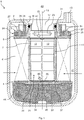
- Fig. 1 shows a sectional view of a filter device 1 according to an embodiment.
- the filter device 1 can be provided in a motor vehicle, for example.
- the filter device 1 can be set up to clean a liquid, in particular a urea solution.
- the filter device 1 comprises a housing 2 in which a filter element 3 is arranged.
- the filter element 3 comprises a first, lower end disk 4 and a second, upper end disk 5.
- a first filter medium 6 in the form of a bellows is arranged between the two end disks 4, 5.
- the bellows or the first filter medium 6 has, for example, in cross section (perpendicular to the plane of the paper) an annular cross section and is welded to the end disks 4, 5 in a fluid-tight manner at its opposite ends.
- a support body in the form of a central tube 11 is arranged in the interior space 7 enclosed by the first filter medium 6.
- the central tube 11 has radial openings 12 towards the first filter medium 6. “Radial”, “axial” and “in the circumferential direction” relate to a central axis 13 of the filter element 3.
- An axial collar 14 of the filter element 3 extends from the end disk 5 into a connection opening 15 of the housing 2 and seals against it on the outside, for example by means of an O-ring 16.
- the filter element 3 is releasably fastened in the connection opening 15 and can be exchanged if necessary.
- the collar 14 has an opening 17 which is connected to the interior 21 of the central tube 11 in a fluid-conducting manner.
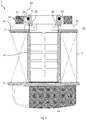
- Fig. 2 shows the filter element 3 from Fig. 1 isolated and in a section perpendicular to that in Fig. 1 illustrated level.
- Fig. 3 shows the filter element 3 from Fig. 1 and 2 in a perspective view from diagonally above. Based on Fig. 2 and 3 the structure of the collar 14 is explained in more detail below.
- the collar 14 has, for example, two elongated holes 22 each extending in the circumferential direction.
- the elongated holes 22 each form through openings through the collar 14 in the radial direction.
- the elongated holes 22 are, as in Fig. 2 to be seen, each closed by a second filter medium 23.
- the second filter media 23 are each injected into the collar 14. While the first filter medium 6 is made of a hydrophilic material, for example paper, the second filter media 23 are each made of a hydrophobic material. For this purpose, the second filter media 23 can be made of PTFE.
- the elongated holes 22 and thus the second filter media 23 are arranged (geodetically) higher than the first filter medium 6 in the illustrated operating position of the filter element 3.
- the filter element 3 has a first compensation element 24.
- the compensation element 24 is composed of a radial section 25 and an axial section 26.
- the radial section 25 rests on the top side of the end disk 5 and can be positively connected to it with the aid of pegs 27.
- the axial section 26 extends parallel to the collar 14, so that an annular gap 28 results in which a stub 31 of the housing 2 that forms the connection opening 15 is received, see FIG Fig. 1 .
- two channels 32 in the form of grooves are formed in the first compensation element 24, each of which extends radially towards the elongated holes 22 or the second filter media 23.
- a respective channel 23 is delimited on the underside by the upper end plate 5.
- the lower end plate 4 can, as for example in Fig. 1 shown have an opening 33.
- a cross 34 is arranged so that the opening 33 in Fig. 1 can only be hinted at.
- the cross 34 protects a third, optionally provided filter medium 35 from manual damage.
- the third filter medium 35 is arranged on the inside with respect to the cross 34, ie on the side of the interior 21.
- the opening 33 is closed by the third filter medium 35.
- the third filter medium 35 is also made hydrophilic according to the exemplary embodiment.
- the third filter medium 35 can be formed from a polyamide fleece.
- the third filter medium 35 is connected to the central tube 11, for example by injection-molding around the third filter medium 35.
- the edge region 36 of the third filter medium 35 is welded all the way around to an edge region 37 of the end disk 4 that delimits the opening 33.
- the filter media 6, 23 and 35 subdivide the filter device 1 into a raw side 41 and a clean side 42.
- liquid to be cleaned in particular urea solution, which when the filter device 1 is in operation, for example via a connection 43 (see Fig. 1 ) is supplied and essentially only flows through the first filter medium 6 and is cleaned in the process.
- the liquid thus reaches the clean side 42 and is fed there, for example, to an exhaust line of the motor vehicle.
- a pump for applying a vacuum to the filter element 3 or to its interior 21 can be provided on the clean side 42.
- the application of the vacuum causes the liquid to outgas and thus gas to accumulate in a (geodetically) high area of the filter device 2.
- the first filter medium 6 is essentially impenetrable for the gas, since the latter soaks up the liquid and thus forms a barrier.
- the second filter media 23, on the other hand, repel the liquid and are permeable to the gases. Gas on the raw side 41 can thus be fed through the channels 32 to the elongated holes 22 or the filter media 23, where it can pass through the filter media 23 in the form of small bubbles and be fed to the exhaust line in a harmless manner.
- the operating pressure difference which is applied to the filter media 6, 23, 35 is selected, for example, in a range between 0 and 0.7 bar (vacuum operation).
- the first filter medium 6 (and possibly the third filter medium 35) is, for example, liquid-permeable above a pressure difference of 0 bar, while the second filter media 23 only become liquid-permeable from a pressure of, for example, 1.0 bar. This then leads to the effect that when the filter device 1 is in operation, liquid only flows through the first filter medium 6 (and possibly through the third filter medium 35, although due to its design only very little liquid flows through it) and gas flows through the second filter media 23 delivered through the opening 17 become.
- the filter element 3 can have a second compensation element 44 below the lower end plate 4.
- the second compensation element 44 can also be formed from EPDM. If the filter device 1 is exposed to very cold conditions, for example in winter, the liquid, in particular the urea solution, in the housing 2 can freeze. Freezing takes place in the in Fig. 1 direction indicated by several arrows from the outside to the inside instead.
- the compensation bodies 24, 44 are designed to accommodate a volume of liquid that increases when the liquid, in particular the urea solution, freezes. In addition, it can be provided that a residual liquid 45 freezes last due to the isolator effect of the compensation element 44.
- a pressure build-up which is associated with freezing of the residual liquid 45 and could damage the filter element 3, is avoided in that the residual liquid 45 can flow through the third filter medium 35 into a gap 46 between the end plate 4 and the compensation element 44.
- the compensation element 44 can, for example, lie directly against the end disk 4, as in FIG Fig. 1 shown.
- the gap 46 is then gradually formed as the residual liquid 45 flows out through the third filter medium 35.
- the above-mentioned principle is also applicable to oils or oil-based liquids.
- the first filter medium 6 is oleophilic and the second filter medium 23 is oleophobic.
Landscapes
- Chemical & Material Sciences (AREA)
- Chemical Kinetics & Catalysis (AREA)
- Exhaust Gas After Treatment (AREA)
- Filtration Of Liquid (AREA)
Claims (13)
- Élément filtrant (3) destiné à la filtration d'un liquide, notamment d'une solution d'urée, l'élément filtrant entourant un espace intérieur de manière annulaire et pouvant être parcouru, d'un côté brut (41) vers un côté pur (42), parallèlement par au moins un premier (6) milieu filtrant et un deuxième (23) milieu filtrant qui sont disposés respectivement entre le côté brut et le côté pur (41, 42) de l'élément filtrant (3), le premier milieu filtrant (6) étant perméable aux liquides et imperméable aux gaz et le deuxième milieu filtrant (23) étant imperméable aux liquides et perméable aux gaz, et le premier milieu filtrant (6) comportant un disque d'extrémité (5) sur une face frontale ou sur les deux faces frontales et le deuxième milieu filtrant (23) étant disposé dans une ouverture (22) dans un disque d'extrémité (5).
- Élément filtrant selon la revendication 1, le premier milieu filtrant (6) étant hydrophile ou oléophile et le deuxième milieu filtrant (23) étant hydrophobe ou oléophobe.
- Élément filtrant selon la revendication 1 ou 2, le premier milieu filtrant (6) étant imperméable aux gaz et perméable aux liquides en dessus d'une première pression différentielle et le deuxième milieu filtrant (23) étant perméable aux gaz et imperméable aux liquides en dessous d'une seconde pression différentielle, la seconde pression différentielle étant supérieure à la première pression différentielle et une pression différentielle d'exploitation à laquelle l'élément filtrant (3) peut être utilisé étant située entre la première pression différentielle et la seconde pression différentielle.
- Élément filtrant selon l'une des revendications précédentes, le premier milieu filtrant (6) étant fermé de manière annulaire et, plié en forme d'étoile ou enroulé, entourant l'espace intérieur.
- Élément filtrant selon l'une des revendications précédentes, le deuxième milieu filtrant (23) étant exécuté dans une ouverture (22) d'un collet (14) de l'élément filtrant (3) faisant saillie d'un disque d'extrémité (5), ce collet constituant un raccord de l'élément filtrant (3) permettant d'évacuer du fluide filtré ou d'introduire du fluide à filtrer.
- Élément filtrant selon l'une des revendications précédentes, l'ouverture (22) étant exécutée en tant que trou oblong.
- Élément filtrant selon la revendication 5 ou 6, l'ouverture (22) traversant le collet (14) en sens radial.
- Élément filtrant selon l'une des revendications 1 à 5, le deuxième milieu filtrant (23) étant injecté dans le disque d'extrémité (5) ou le collet (14).
- Élément filtrant selon l'une des revendications 1 à 5, un élément de compensation (24, 44) étant prévu du côté brut (41) de manière à ce que, en cas de gel du fluide, du fluide résiduel (45, 47) coule à travers le deuxième milieu filtrant (23) ou un troisième milieu filtrant (35), dans un interstice (46, 51) ménagé entre le deuxième milieu filtrant (23) ou le troisième milieu filtrant (35) et l'élément de compensation (24, 44).
- Élément filtrant selon l'une des revendications 1 à 6, un élément de compensation (24) comportant un canal (32) reliant l'ouverture (22) au côté brut (41) étant prévu.
- Élément filtrant selon l'une des revendications 1 à 10, l'élément filtrant (3) étant exécuté en tant qu'élément filtrant pour urée.
- Dispositif de filtration (1), notamment dispositif de filtration pour urée, ayant un élément filtrant (3) selon l'une des revendications 1 à 11.
- Dispositif de filtration selon la revendication 12, le deuxième milieu filtrant (23) étant exécuté dans une ouverture d'un collet (14) de l'élément filtrant (3) faisant saillie d'un disque d'extrémité (5), le collet constituant un raccord de l'élément filtrant (3) permettant d'évacuer du fluide filtré ou d'introduire du fluide à filtrer, le collet (14) dépassant vers le haut, notamment en s'écartant du premier milieu filtrant (6).
Applications Claiming Priority (2)
| Application Number | Priority Date | Filing Date | Title |
|---|---|---|---|
| DE102012017140.4A DE102012017140B4 (de) | 2012-08-30 | 2012-08-30 | Filterelement sowie Filtereinrichtung |
| PCT/EP2013/066181 WO2014032902A1 (fr) | 2012-08-30 | 2013-08-01 | Elément filtrant et dispositif filtrant |
Publications (2)
| Publication Number | Publication Date |
|---|---|
| EP2890472A1 EP2890472A1 (fr) | 2015-07-08 |
| EP2890472B1 true EP2890472B1 (fr) | 2021-07-07 |
Family
ID=48948400
Family Applications (1)
| Application Number | Title | Priority Date | Filing Date |
|---|---|---|---|
| EP13745821.2A Active EP2890472B1 (fr) | 2012-08-30 | 2013-08-01 | Elément filtrant et dispositif filtrant |
Country Status (5)
| Country | Link |
|---|---|
| US (1) | US9731224B2 (fr) |
| EP (1) | EP2890472B1 (fr) |
| CN (1) | CN104582811B (fr) |
| DE (1) | DE102012017140B4 (fr) |
| WO (1) | WO2014032902A1 (fr) |
Families Citing this family (14)
| Publication number | Priority date | Publication date | Assignee | Title |
|---|---|---|---|---|
| DE102012222943B4 (de) | 2012-12-12 | 2022-01-13 | Robert Bosch Gmbh | Filterelement, Filtervorrichtung, Tankvorrichtung und Verfahren zur Herstellung und Inbetriebnahme |
| DE102014013852A1 (de) | 2014-09-24 | 2016-03-24 | Mann + Hummel Gmbh | Filterelement, Filter und Filtersystem mit Rücklaufbypass |
| ES2793941T3 (es) | 2015-01-06 | 2020-11-17 | A L Filter Co Ltd | Filtro de líquido resistente al congelamiento |
| US10914228B2 (en) | 2016-11-15 | 2021-02-09 | Cummins Inc. | Waste heat recovery with active coolant pressure control system |
| DE102017203796B4 (de) | 2017-03-08 | 2021-03-18 | Robert Bosch Gmbh | Flüssigkeitsfilter mit einem Verdrängungskörper und Filterkartusche mit einem Verdrängungskörper |
| CN113476924B (zh) * | 2017-04-06 | 2023-04-07 | 佛山市顺德区美的饮水机制造有限公司 | 复合滤芯及净水设备 |
| CN108793301A (zh) * | 2017-05-03 | 2018-11-13 | 杭州大立过滤设备有限公司 | 一款亲水疏水一体型滤芯 |
| US11766631B2 (en) * | 2017-09-19 | 2023-09-26 | C.C. Jensen A/S | Internal continuous air bypass |
| DE102017011279A1 (de) | 2017-12-07 | 2019-06-13 | Mann+Hummel Gmbh | Rundfilterelement eines Filters für Harnstoff-Wasser-Lösung und Filter |
| US10411380B1 (en) * | 2018-05-24 | 2019-09-10 | Microsoft Technology Licensing, Llc | Connectors with liquid metal and gas permeable plugs |
| CN108952902A (zh) * | 2018-07-17 | 2018-12-07 | 山东艾泰克环保科技股份有限公司 | 一种柴油发动机scr系统喷射装置用防堵塞机构 |
| US11344826B2 (en) * | 2019-04-03 | 2022-05-31 | Caterpillar Inc. | Machine fluid system having filter protector for sock filter in manifold tube assembly |
| CN112237770B (zh) * | 2019-07-16 | 2024-01-05 | 上海索菲玛汽车滤清器有限公司 | 具有补偿装置的过滤器滤芯 |
| DE102020131655A1 (de) | 2020-11-30 | 2022-06-02 | Airbus Operations Gmbh | Filtervorrichtung für eine Öl aufweisende Vorrichtung in einem Fahrzeug |
Family Cites Families (10)
| Publication number | Priority date | Publication date | Assignee | Title |
|---|---|---|---|---|
| DE3304951A1 (de) | 1983-02-12 | 1984-08-16 | Akzo Gmbh, 5600 Wuppertal | Vorrichtung zum filtern einer fluessigkeit |
| EP0773053B1 (fr) * | 1995-11-10 | 2003-02-05 | MAHLE Filtersysteme GmbH | Filtre pour liquide s'écoulant dans un réservoir fermé |
| DE19905645C1 (de) * | 1999-02-11 | 2000-10-26 | Sartorius Gmbh | Filteraufsatz zur Vakuumfiltration |
| DE19939970B4 (de) * | 1999-08-24 | 2006-11-16 | Schuler Pressen Gmbh & Co. Kg | Vorrichtung zur Filterung von Öl und zur Abscheidung von Luft aus Öl in Hydrauliksystemen |
| JP2003509186A (ja) | 1999-09-17 | 2003-03-11 | マイクロリス・コーポレイシヨン | スラリーを濾過するためのフィルタカートリッジ |
| DE10345818A1 (de) * | 2003-09-30 | 2005-04-28 | Boehringer Ingelheim Micropart | Verfahren und Vorrichtung zum Separieren und Abführen von Gasblasen aus Flüssigkeiten |
| DE102009023951B3 (de) | 2009-06-04 | 2011-01-05 | Mann + Hummel Gmbh | Filtereinrichtung zur Flüssigkeitsfiltrierung |
| DE102009061063B4 (de) * | 2009-06-04 | 2013-09-12 | Mann + Hummel Gmbh | Filtereinrichtung zur Flüssigkeitsfiltrierung |
| US20110088662A1 (en) * | 2009-10-20 | 2011-04-21 | Eaton Corporation | Method of packaging a membrane for use in a venting valve |
| CN102596355A (zh) * | 2009-11-12 | 2012-07-18 | 唐纳森公司 | 用于冻结环境的液体过滤器结构 |
-
2012
- 2012-08-30 DE DE102012017140.4A patent/DE102012017140B4/de not_active Expired - Fee Related
-
2013
- 2013-08-01 CN CN201380045089.7A patent/CN104582811B/zh active Active
- 2013-08-01 EP EP13745821.2A patent/EP2890472B1/fr active Active
- 2013-08-01 WO PCT/EP2013/066181 patent/WO2014032902A1/fr unknown
-
2015
- 2015-02-27 US US14/634,135 patent/US9731224B2/en active Active
Non-Patent Citations (1)
| Title |
|---|
| None * |
Also Published As
| Publication number | Publication date |
|---|---|
| DE102012017140A1 (de) | 2014-03-06 |
| CN104582811A (zh) | 2015-04-29 |
| US20150165344A1 (en) | 2015-06-18 |
| WO2014032902A1 (fr) | 2014-03-06 |
| US9731224B2 (en) | 2017-08-15 |
| EP2890472A1 (fr) | 2015-07-08 |
| CN104582811B (zh) | 2018-04-06 |
| DE102012017140B4 (de) | 2016-04-07 |
Similar Documents
| Publication | Publication Date | Title |
|---|---|---|
| EP2890472B1 (fr) | Elément filtrant et dispositif filtrant | |
| EP3525913B1 (fr) | Élément filtrant rond, en particulier pour la filtration de gaz | |
| EP3004620B1 (fr) | Élément filtrant | |
| WO2009080706A1 (fr) | Système de filtre, en particulier filtre à liquide | |
| EP1933968A1 (fr) | Filtre a carburant | |
| EP2682172A2 (fr) | Dispositif de filtration et élément filtrant destiné à un tel dispositif de filtration | |
| EP2579958B1 (fr) | Dispositif de filtration, en particulier filtre pour liquides | |
| DE102006029108A1 (de) | Verfahren und Anordnung zur Steuerung von Flüssigkeitsströmen | |
| EP2865433A2 (fr) | Élément de filtre et système de filtre pour un milieu fluidique, notamment du carburant diesel | |
| WO2018072928A1 (fr) | Installation de filtre et élément de filtre rond, en particulier pour la filtration de gaz | |
| WO2015018779A1 (fr) | Crible séparateur d'eau pour un élément filtrant dans un filtre de liquide | |
| EP2886181B1 (fr) | Filtre à liquide | |
| WO2015082117A1 (fr) | Dispositif de filtrage avec adaptateur | |
| DE102005043968A1 (de) | Filtereinrichtung mit einer Durchgangsöffnung zum Abführen von Luft | |
| EP2808071B1 (fr) | Dispositif de filtre, en particulier pour un véhicule automobile | |
| DE102005058109B4 (de) | Verwendung einer Filtereinheit mit einer Sollbruchstelle | |
| EP3000520B1 (fr) | Insert de filtre | |
| DE102009048588A1 (de) | Filtereinrichtung, insbesondere zur Flüssigkeitsfilterung in Brennkraftmaschinen | |
| DE112017005176T5 (de) | In den oberen flansch integrierte entlüftungsfilterpatrone und filtration | |
| EP3160614B1 (fr) | Système de filtration et filtre pour liquides | |
| EP3618941A1 (fr) | Élément filtrant pour filtration de liquide | |
| DE102013004865B4 (de) | Filtereinrichtung mit einem ringförmigen Filterelement | |
| DE102013001843A1 (de) | Filterelement zum Filtern von Flüssigkeit, insbesondere von Harnstofflösung | |
| EP4115964B1 (fr) | Dispositif filtre | |
| DE102012012543B4 (de) | Filteranordnung |
Legal Events
| Date | Code | Title | Description |
|---|---|---|---|
| PUAI | Public reference made under article 153(3) epc to a published international application that has entered the european phase |
Free format text: ORIGINAL CODE: 0009012 |
|
| 17P | Request for examination filed |
Effective date: 20150204 |
|
| AK | Designated contracting states |
Kind code of ref document: A1 Designated state(s): AL AT BE BG CH CY CZ DE DK EE ES FI FR GB GR HR HU IE IS IT LI LT LU LV MC MK MT NL NO PL PT RO RS SE SI SK SM TR |
|
| AX | Request for extension of the european patent |
Extension state: BA ME |
|
| DAX | Request for extension of the european patent (deleted) | ||
| STAA | Information on the status of an ep patent application or granted ep patent |
Free format text: STATUS: EXAMINATION IS IN PROGRESS |
|
| 17Q | First examination report despatched |
Effective date: 20180209 |
|
| STAA | Information on the status of an ep patent application or granted ep patent |
Free format text: STATUS: EXAMINATION IS IN PROGRESS |
|
| RAP1 | Party data changed (applicant data changed or rights of an application transferred) |
Owner name: MANN+HUMMEL GMBH |
|
| GRAP | Despatch of communication of intention to grant a patent |
Free format text: ORIGINAL CODE: EPIDOSNIGR1 |
|
| STAA | Information on the status of an ep patent application or granted ep patent |
Free format text: STATUS: GRANT OF PATENT IS INTENDED |
|
| GRAJ | Information related to disapproval of communication of intention to grant by the applicant or resumption of examination proceedings by the epo deleted |
Free format text: ORIGINAL CODE: EPIDOSDIGR1 |
|
| STAA | Information on the status of an ep patent application or granted ep patent |
Free format text: STATUS: EXAMINATION IS IN PROGRESS |
|
| INTG | Intention to grant announced |
Effective date: 20201222 |
|
| GRAP | Despatch of communication of intention to grant a patent |
Free format text: ORIGINAL CODE: EPIDOSNIGR1 |
|
| STAA | Information on the status of an ep patent application or granted ep patent |
Free format text: STATUS: GRANT OF PATENT IS INTENDED |
|
| INTC | Intention to grant announced (deleted) | ||
| INTG | Intention to grant announced |
Effective date: 20210209 |
|
| GRAJ | Information related to disapproval of communication of intention to grant by the applicant or resumption of examination proceedings by the epo deleted |
Free format text: ORIGINAL CODE: EPIDOSDIGR1 |
|
| STAA | Information on the status of an ep patent application or granted ep patent |
Free format text: STATUS: EXAMINATION IS IN PROGRESS |
|
| GRAP | Despatch of communication of intention to grant a patent |
Free format text: ORIGINAL CODE: EPIDOSNIGR1 |
|
| STAA | Information on the status of an ep patent application or granted ep patent |
Free format text: STATUS: GRANT OF PATENT IS INTENDED |
|
| INTC | Intention to grant announced (deleted) | ||
| INTG | Intention to grant announced |
Effective date: 20210408 |
|
| RAP3 | Party data changed (applicant data changed or rights of an application transferred) |
Owner name: MANN+HUMMEL GMBH |
|
| GRAS | Grant fee paid |
Free format text: ORIGINAL CODE: EPIDOSNIGR3 |
|
| GRAA | (expected) grant |
Free format text: ORIGINAL CODE: 0009210 |
|
| STAA | Information on the status of an ep patent application or granted ep patent |
Free format text: STATUS: THE PATENT HAS BEEN GRANTED |
|
| AK | Designated contracting states |
Kind code of ref document: B1 Designated state(s): AL AT BE BG CH CY CZ DE DK EE ES FI FR GB GR HR HU IE IS IT LI LT LU LV MC MK MT NL NO PL PT RO RS SE SI SK SM TR |
|
| REG | Reference to a national code |
Ref country code: GB Ref legal event code: FG4D Free format text: NOT ENGLISH |
|
| REG | Reference to a national code |
Ref country code: AT Ref legal event code: REF Ref document number: 1408001 Country of ref document: AT Kind code of ref document: T Effective date: 20210715 |
|
| REG | Reference to a national code |
Ref country code: DE Ref legal event code: R096 Ref document number: 502013015820 Country of ref document: DE |
|
| REG | Reference to a national code |
Ref country code: IE Ref legal event code: FG4D Free format text: LANGUAGE OF EP DOCUMENT: GERMAN |
|
| REG | Reference to a national code |
Ref country code: LT Ref legal event code: MG9D |
|
| REG | Reference to a national code |
Ref country code: NL Ref legal event code: MP Effective date: 20210707 |
|
| PG25 | Lapsed in a contracting state [announced via postgrant information from national office to epo] |
Ref country code: HR Free format text: LAPSE BECAUSE OF FAILURE TO SUBMIT A TRANSLATION OF THE DESCRIPTION OR TO PAY THE FEE WITHIN THE PRESCRIBED TIME-LIMIT Effective date: 20210707 Ref country code: SE Free format text: LAPSE BECAUSE OF FAILURE TO SUBMIT A TRANSLATION OF THE DESCRIPTION OR TO PAY THE FEE WITHIN THE PRESCRIBED TIME-LIMIT Effective date: 20210707 Ref country code: PT Free format text: LAPSE BECAUSE OF FAILURE TO SUBMIT A TRANSLATION OF THE DESCRIPTION OR TO PAY THE FEE WITHIN THE PRESCRIBED TIME-LIMIT Effective date: 20211108 Ref country code: NO Free format text: LAPSE BECAUSE OF FAILURE TO SUBMIT A TRANSLATION OF THE DESCRIPTION OR TO PAY THE FEE WITHIN THE PRESCRIBED TIME-LIMIT Effective date: 20211007 Ref country code: RS Free format text: LAPSE BECAUSE OF FAILURE TO SUBMIT A TRANSLATION OF THE DESCRIPTION OR TO PAY THE FEE WITHIN THE PRESCRIBED TIME-LIMIT Effective date: 20210707 Ref country code: NL Free format text: LAPSE BECAUSE OF FAILURE TO SUBMIT A TRANSLATION OF THE DESCRIPTION OR TO PAY THE FEE WITHIN THE PRESCRIBED TIME-LIMIT Effective date: 20210707 Ref country code: ES Free format text: LAPSE BECAUSE OF FAILURE TO SUBMIT A TRANSLATION OF THE DESCRIPTION OR TO PAY THE FEE WITHIN THE PRESCRIBED TIME-LIMIT Effective date: 20210707 Ref country code: FI Free format text: LAPSE BECAUSE OF FAILURE TO SUBMIT A TRANSLATION OF THE DESCRIPTION OR TO PAY THE FEE WITHIN THE PRESCRIBED TIME-LIMIT Effective date: 20210707 Ref country code: LT Free format text: LAPSE BECAUSE OF FAILURE TO SUBMIT A TRANSLATION OF THE DESCRIPTION OR TO PAY THE FEE WITHIN THE PRESCRIBED TIME-LIMIT Effective date: 20210707 Ref country code: BG Free format text: LAPSE BECAUSE OF FAILURE TO SUBMIT A TRANSLATION OF THE DESCRIPTION OR TO PAY THE FEE WITHIN THE PRESCRIBED TIME-LIMIT Effective date: 20211007 |
|
| PG25 | Lapsed in a contracting state [announced via postgrant information from national office to epo] |
Ref country code: PL Free format text: LAPSE BECAUSE OF FAILURE TO SUBMIT A TRANSLATION OF THE DESCRIPTION OR TO PAY THE FEE WITHIN THE PRESCRIBED TIME-LIMIT Effective date: 20210707 Ref country code: LV Free format text: LAPSE BECAUSE OF FAILURE TO SUBMIT A TRANSLATION OF THE DESCRIPTION OR TO PAY THE FEE WITHIN THE PRESCRIBED TIME-LIMIT Effective date: 20210707 Ref country code: GR Free format text: LAPSE BECAUSE OF FAILURE TO SUBMIT A TRANSLATION OF THE DESCRIPTION OR TO PAY THE FEE WITHIN THE PRESCRIBED TIME-LIMIT Effective date: 20211008 |
|
| REG | Reference to a national code |
Ref country code: CH Ref legal event code: PL |
|
| REG | Reference to a national code |
Ref country code: DE Ref legal event code: R097 Ref document number: 502013015820 Country of ref document: DE |
|
| REG | Reference to a national code |
Ref country code: BE Ref legal event code: MM Effective date: 20210831 |
|
| PG25 | Lapsed in a contracting state [announced via postgrant information from national office to epo] |
Ref country code: LI Free format text: LAPSE BECAUSE OF NON-PAYMENT OF DUE FEES Effective date: 20210831 Ref country code: DK Free format text: LAPSE BECAUSE OF FAILURE TO SUBMIT A TRANSLATION OF THE DESCRIPTION OR TO PAY THE FEE WITHIN THE PRESCRIBED TIME-LIMIT Effective date: 20210707 Ref country code: CH Free format text: LAPSE BECAUSE OF NON-PAYMENT OF DUE FEES Effective date: 20210831 |
|
| PLBE | No opposition filed within time limit |
Free format text: ORIGINAL CODE: 0009261 |
|
| STAA | Information on the status of an ep patent application or granted ep patent |
Free format text: STATUS: NO OPPOSITION FILED WITHIN TIME LIMIT |
|
| PG25 | Lapsed in a contracting state [announced via postgrant information from national office to epo] |
Ref country code: SM Free format text: LAPSE BECAUSE OF FAILURE TO SUBMIT A TRANSLATION OF THE DESCRIPTION OR TO PAY THE FEE WITHIN THE PRESCRIBED TIME-LIMIT Effective date: 20210707 Ref country code: SK Free format text: LAPSE BECAUSE OF FAILURE TO SUBMIT A TRANSLATION OF THE DESCRIPTION OR TO PAY THE FEE WITHIN THE PRESCRIBED TIME-LIMIT Effective date: 20210707 Ref country code: RO Free format text: LAPSE BECAUSE OF FAILURE TO SUBMIT A TRANSLATION OF THE DESCRIPTION OR TO PAY THE FEE WITHIN THE PRESCRIBED TIME-LIMIT Effective date: 20210707 Ref country code: MC Free format text: LAPSE BECAUSE OF FAILURE TO SUBMIT A TRANSLATION OF THE DESCRIPTION OR TO PAY THE FEE WITHIN THE PRESCRIBED TIME-LIMIT Effective date: 20210707 Ref country code: LU Free format text: LAPSE BECAUSE OF NON-PAYMENT OF DUE FEES Effective date: 20210801 Ref country code: EE Free format text: LAPSE BECAUSE OF FAILURE TO SUBMIT A TRANSLATION OF THE DESCRIPTION OR TO PAY THE FEE WITHIN THE PRESCRIBED TIME-LIMIT Effective date: 20210707 Ref country code: CZ Free format text: LAPSE BECAUSE OF FAILURE TO SUBMIT A TRANSLATION OF THE DESCRIPTION OR TO PAY THE FEE WITHIN THE PRESCRIBED TIME-LIMIT Effective date: 20210707 Ref country code: AL Free format text: LAPSE BECAUSE OF FAILURE TO SUBMIT A TRANSLATION OF THE DESCRIPTION OR TO PAY THE FEE WITHIN THE PRESCRIBED TIME-LIMIT Effective date: 20210707 |
|
| 26N | No opposition filed |
Effective date: 20220408 |
|
| PG25 | Lapsed in a contracting state [announced via postgrant information from national office to epo] |
Ref country code: IE Free format text: LAPSE BECAUSE OF NON-PAYMENT OF DUE FEES Effective date: 20210801 Ref country code: BE Free format text: LAPSE BECAUSE OF NON-PAYMENT OF DUE FEES Effective date: 20210831 |
|
| REG | Reference to a national code |
Ref country code: AT Ref legal event code: MM01 Ref document number: 1408001 Country of ref document: AT Kind code of ref document: T Effective date: 20210801 |
|
| PG25 | Lapsed in a contracting state [announced via postgrant information from national office to epo] |
Ref country code: AT Free format text: LAPSE BECAUSE OF NON-PAYMENT OF DUE FEES Effective date: 20210801 |
|
| PG25 | Lapsed in a contracting state [announced via postgrant information from national office to epo] |
Ref country code: HU Free format text: LAPSE BECAUSE OF FAILURE TO SUBMIT A TRANSLATION OF THE DESCRIPTION OR TO PAY THE FEE WITHIN THE PRESCRIBED TIME-LIMIT; INVALID AB INITIO Effective date: 20130801 |
|
| PG25 | Lapsed in a contracting state [announced via postgrant information from national office to epo] |
Ref country code: CY Free format text: LAPSE BECAUSE OF FAILURE TO SUBMIT A TRANSLATION OF THE DESCRIPTION OR TO PAY THE FEE WITHIN THE PRESCRIBED TIME-LIMIT Effective date: 20210707 |
|
| P01 | Opt-out of the competence of the unified patent court (upc) registered |
Effective date: 20230627 |
|
| PGFP | Annual fee paid to national office [announced via postgrant information from national office to epo] |
Ref country code: IT Payment date: 20230825 Year of fee payment: 11 Ref country code: GB Payment date: 20230822 Year of fee payment: 11 |
|
| PGFP | Annual fee paid to national office [announced via postgrant information from national office to epo] |
Ref country code: FR Payment date: 20230824 Year of fee payment: 11 Ref country code: DE Payment date: 20230821 Year of fee payment: 11 |
|
| PG25 | Lapsed in a contracting state [announced via postgrant information from national office to epo] |
Ref country code: MK Free format text: LAPSE BECAUSE OF FAILURE TO SUBMIT A TRANSLATION OF THE DESCRIPTION OR TO PAY THE FEE WITHIN THE PRESCRIBED TIME-LIMIT Effective date: 20210707 |