EP2890472B1 - Filter element and filter device - Google Patents
Filter element and filter device Download PDFInfo
- Publication number
- EP2890472B1 EP2890472B1 EP13745821.2A EP13745821A EP2890472B1 EP 2890472 B1 EP2890472 B1 EP 2890472B1 EP 13745821 A EP13745821 A EP 13745821A EP 2890472 B1 EP2890472 B1 EP 2890472B1
- Authority
- EP
- European Patent Office
- Prior art keywords
- filter
- filter element
- filter medium
- medium
- collar
- Prior art date
- Legal status (The legal status is an assumption and is not a legal conclusion. Google has not performed a legal analysis and makes no representation as to the accuracy of the status listed.)
- Active
Links
Images

Classifications
-
- B—PERFORMING OPERATIONS; TRANSPORTING
- B01—PHYSICAL OR CHEMICAL PROCESSES OR APPARATUS IN GENERAL
- B01D—SEPARATION
- B01D19/00—Degasification of liquids
- B01D19/0031—Degasification of liquids by filtration
-
- B—PERFORMING OPERATIONS; TRANSPORTING
- B01—PHYSICAL OR CHEMICAL PROCESSES OR APPARATUS IN GENERAL
- B01D—SEPARATION
- B01D36/00—Filter circuits or combinations of filters with other separating devices
- B01D36/001—Filters in combination with devices for the removal of gas, air purge systems
-
- B—PERFORMING OPERATIONS; TRANSPORTING
- B01—PHYSICAL OR CHEMICAL PROCESSES OR APPARATUS IN GENERAL
- B01D—SEPARATION
- B01D29/00—Filters with filtering elements stationary during filtration, e.g. pressure or suction filters, not covered by groups B01D24/00 - B01D27/00; Filtering elements therefor
- B01D29/11—Filters with filtering elements stationary during filtration, e.g. pressure or suction filters, not covered by groups B01D24/00 - B01D27/00; Filtering elements therefor with bag, cage, hose, tube, sleeve or like filtering elements
- B01D29/13—Supported filter elements
- B01D29/15—Supported filter elements arranged for inward flow filtration
- B01D29/21—Supported filter elements arranged for inward flow filtration with corrugated, folded or wound sheets
-
- B—PERFORMING OPERATIONS; TRANSPORTING
- B01—PHYSICAL OR CHEMICAL PROCESSES OR APPARATUS IN GENERAL
- B01D—SEPARATION
- B01D29/00—Filters with filtering elements stationary during filtration, e.g. pressure or suction filters, not covered by groups B01D24/00 - B01D27/00; Filtering elements therefor
- B01D29/50—Filters with filtering elements stationary during filtration, e.g. pressure or suction filters, not covered by groups B01D24/00 - B01D27/00; Filtering elements therefor with multiple filtering elements, characterised by their mutual disposition
- B01D29/52—Filters with filtering elements stationary during filtration, e.g. pressure or suction filters, not covered by groups B01D24/00 - B01D27/00; Filtering elements therefor with multiple filtering elements, characterised by their mutual disposition in parallel connection
- B01D29/54—Filters with filtering elements stationary during filtration, e.g. pressure or suction filters, not covered by groups B01D24/00 - B01D27/00; Filtering elements therefor with multiple filtering elements, characterised by their mutual disposition in parallel connection arranged concentrically or coaxially
-
- B—PERFORMING OPERATIONS; TRANSPORTING
- B01—PHYSICAL OR CHEMICAL PROCESSES OR APPARATUS IN GENERAL
- B01D—SEPARATION
- B01D29/00—Filters with filtering elements stationary during filtration, e.g. pressure or suction filters, not covered by groups B01D24/00 - B01D27/00; Filtering elements therefor
- B01D29/88—Filters with filtering elements stationary during filtration, e.g. pressure or suction filters, not covered by groups B01D24/00 - B01D27/00; Filtering elements therefor having feed or discharge devices
- B01D29/90—Filters with filtering elements stationary during filtration, e.g. pressure or suction filters, not covered by groups B01D24/00 - B01D27/00; Filtering elements therefor having feed or discharge devices for feeding
- B01D29/902—Filters with filtering elements stationary during filtration, e.g. pressure or suction filters, not covered by groups B01D24/00 - B01D27/00; Filtering elements therefor having feed or discharge devices for feeding containing fixed liquid displacement elements or cores
-
- B—PERFORMING OPERATIONS; TRANSPORTING
- B01—PHYSICAL OR CHEMICAL PROCESSES OR APPARATUS IN GENERAL
- B01D—SEPARATION
- B01D2201/00—Details relating to filtering apparatus
- B01D2201/40—Special measures for connecting different parts of the filter
- B01D2201/403—Special measures for connecting different parts of the filter allowing dilatation, e.g. by heat
Definitions
- the present invention relates to a filter element for filtering a fluid, in particular a urea solution, and to a filter device, in particular a urea filter device.
- urea solutions are used in exhaust gas treatment in motor vehicles to reduce nitrogen oxide emissions.
- Urea solution is injected through nozzles in the exhaust system.
- the urea solution must be filtered.
- a filter suitable for filtering a urea solution is often also called a urea filter.
- a filter element which is applied or acted upon on the suction side with a vacuum or negative pressure.
- the vacuum causes outgassing of the urea solution, so that gases collect in the highest area of the filter element or a filter device accommodating the filter element. It is important to lead the accumulated gases out of the filter element or the filter device in the form of small bubbles in order not to disturb the function of downstream components, in particular the mentioned nozzles.
- WO 2000 047 310 A1 describes a filter attachment for vacuum filtration of aqueous media for laboratory use.
- the filter element has a tubular hydrophilic microporous membrane filter, the end caps with central on both end faces Openings is enclosed in a fluid-tight manner, the lower opening being connected to a housing outlet.
- the central opening of the upper end cap is closed by a hydrophobic membrane.
- WO 2001 019 490 A1 discloses a method for filtering a slurry using a depth filtration medium. Spacers divide the filter medium into filter segments and define flow paths.
- EP 1 520 609 A1 describes a method and a device for separating and removing gas bubbles from liquids, the liquid being deflected radially.
- the liquid is fed to an inlet filter, then enters a venting chamber from which gas can escape through gas separation material, and exits through an outlet filter made of hydrophilic material that forms pores or small channels.
- US 2011/0088662 A1 discloses a method for assembling a membrane for a vent valve.
- urea solutions freeze at approx. -11 ° C it is for example from the WO 2010/139706 A1 known to provide a compensation body made of elastically deformable material.
- the compensation body takes up a volume that increases when the urea solution freezes.
- WO 2011/060254 A1 describes a liquid filter with a protective device to prevent damage when the liquid freezes in the filter housing.
- the protective device comprises a gas-filled compressible element which is arranged in the filter housing and prevents dangerous pressure building up in the housing.
- One object of the present invention is to provide an improved filter element and an improved filter device.
- it is an object of the present invention to at least reduce the accumulation of large gas bubbles in the filter element or in the filter device.
- a filter element for filtering a fluid in particular a urea solution
- the filter element comprises a liquid-permeable and gas-impermeable first filter medium and a liquid-impermeable and gas-permeable second filter medium.
- the first and second filter medium are each arranged between a raw and a clean side of the filter element.
- the filter element surrounds an inner space in a ring shape and can flow through at least the first and the second filter medium in parallel from a raw side to a clean side, which are each arranged between the raw and a clean side of the filter element, the first filter medium being liquid-permeable and gas-impermeable and the second
- the filter medium is impermeable to liquids and gas-permeable.
- the second filter medium aims to achieve a continuous transport of small gas bubbles from the raw side to the clean side of the filter element. This prevents large amounts of gas from accumulating in the filter element or in a filter device receiving the filter element.
- the first filter medium is, for example, basically gas-permeable, but is blocked in the fully sucked state by the surface tension of the fluid, in particular the urea solution.
- the second filter medium is, for example, basically liquid-permeable, but only from a predetermined differential pressure which is greater than an operating differential pressure that is applied to the second filter medium when the filter element is in operation.
- the second filter medium is preferably arranged (geodetically) higher than the first filter medium.
- the fluid is a liquid, in particular a urea solution.
- the first filter medium can for example be designed as a fleece, scrim or fabric. Furthermore, the first filter medium can be provided in a folded manner, for example in the form of a bellows. Furthermore, the first filter medium can comprise paper.
- the second filter medium can be made of polytetrafluoroethylene (PTFE), for example.
- PTFE polytetrafluoroethylene
- the first filter medium is hydrophilic or oleophilic and the second filter medium is hydrophobic or oleophobic. This ensures that the first filter medium is soaked with water (this generally also includes solutions in water) or oil (this generally also includes solutions in oil) and thus a barrier effect against the passage of gases through the first filter medium is produced. On the other hand, water or oil (here the generalization towards solutions in water or in oil also applies accordingly) cannot penetrate the second filter medium, so that it remains permeable for gases to pass through.
- the first filter medium is gas-impermeable and liquid-permeable above a first differential pressure and the second filter medium is gas-permeable and liquid-impermeable below a second differential pressure, the second differential pressure being greater than the first differential pressure and an operating differential pressure at which the filter element can be operated between the first and second differential pressures.
- the second filter medium on the other hand, remains impermeable to the liquid.
- the first filter medium then has the aforementioned barrier effect against gases, while the second filter medium lets the gases through, in particular in the form of small bubbles.
- the operating differential pressure is preferably in a range between 0 and 0.7 bar.
- the first filter medium is closed in the shape of a ring and, folded or wound in a star shape, surrounds the interior of the filter element.
- an end plate is arranged on one or both end faces of the annularly closed first filter medium, which end plate serves to seal the end face of the first filter medium.
- a connection for discharging filtered fluid or supplying fluid to be filtered is preferably provided in an end disk.
- the second filter medium is arranged in an opening in an end plate. Since the end disk axially closes off the annular filter medium, the second filter medium is thus also arranged at an axial end or the end face of the filter body formed by the annular first filter medium.
- the filter element can thus be used vertically in a filter, with the end with the second filter medium facing upwards. Gas rising upwards in the filter can thus be discharged through the second filter medium above the first filter medium.
- the second filter medium is formed in an opening of a collar of the filter element which protrudes from an end plate and which forms a connection of the filter element for discharging filtered fluid or supplying fluid to be filtered. Because the second filter medium or the opening which closes the second filter medium is arranged in the collar of the filter element, the second filter medium is (geodetically) arranged high. In particular, the opening or the second filter medium is thus arranged above the first filter medium. Gas that migrates from home to the (geodetically) highest point can thus be kept away from the first filter medium and brought into the immediate vicinity of the second filter medium.
- openings can also be provided, each of which is closed by a second filter medium.
- the opening is designed as an elongated hole. This allows a comparatively large opening to be created.
- the elongated hole preferably extends in the circumferential direction of the collar.
- the opening penetrates the collar radially. This makes the opening for the gas easily accessible.
- the second filter medium is injected into the collar. This can be done using the plastic injection molding process. This results in a simple manufacturing process.
- a compensation element is provided on the raw side such that when the fluid freezes residual fluid flows through the second filter medium or a third filter medium into a gap between the second filter medium or the third filter medium and the compensation element.
- This gap can be provided by default or it can only result from the fact that the compensation element recedes when the residual fluid flows through the second or third filter medium onto the raw side.
- the compensation element preferably has an elastomer.
- the compensation element can also be designed with closed pores and / or foamed. The pores can be filled with air.
- the compensation element preferably has an ethylene-propylene-diene rubber (also referred to as “EPDM”) and / or a hydrogenated acrylonitrile-butadiene rubber (also referred to as “HBNR”).
- the compensation element can have a distance between 0 and 20 mm, preferably between 0 and 10 mm, with respect to the second filter medium.
- the compensation element is designed as an insulator.
- the spatial arrangement of the not yet frozen residual fluid in the filter element can be controlled in such a way that it collects in an area adjacent to the second or third filter medium on the clean side.
- the desired insulating property of the compensation element can be provided, for example, in that it has EPDM or HBNR.
- a compensation element which has a channel connecting the opening to the raw side. This ensures a simple transport of gases to the second filter medium.
- the channel can be formed, for example, between the compensation element and a further element, for example an upper end disk of the filter element.
- the channel can also be formed by means of a through opening in the compensation element itself.
- the filter element is designed as a urea filter element.
- a filter device in particular a urea filter device, with the filter element according to the invention is proposed.
- the filter device can have a housing in which the filter element is received.
- the housing can have a connection which can be connected to the connection of the filter element in a sealing manner.
- the collar of the filter element can be pushed sealingly into the connection of the filter device.
- the filter device can have means, in particular a pump, in order to apply a vacuum to the filter element on the clean side.
- the collar protrudes upwards.
- the filter element is arranged or inserted into the filter device in such a way that the collar points towards (geodetically) upwards.
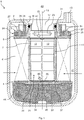
- Fig. 1 shows a sectional view of a filter device 1 according to an embodiment.
- the filter device 1 can be provided in a motor vehicle, for example.
- the filter device 1 can be set up to clean a liquid, in particular a urea solution.
- the filter device 1 comprises a housing 2 in which a filter element 3 is arranged.
- the filter element 3 comprises a first, lower end disk 4 and a second, upper end disk 5.
- a first filter medium 6 in the form of a bellows is arranged between the two end disks 4, 5.
- the bellows or the first filter medium 6 has, for example, in cross section (perpendicular to the plane of the paper) an annular cross section and is welded to the end disks 4, 5 in a fluid-tight manner at its opposite ends.
- a support body in the form of a central tube 11 is arranged in the interior space 7 enclosed by the first filter medium 6.
- the central tube 11 has radial openings 12 towards the first filter medium 6. “Radial”, “axial” and “in the circumferential direction” relate to a central axis 13 of the filter element 3.
- An axial collar 14 of the filter element 3 extends from the end disk 5 into a connection opening 15 of the housing 2 and seals against it on the outside, for example by means of an O-ring 16.
- the filter element 3 is releasably fastened in the connection opening 15 and can be exchanged if necessary.
- the collar 14 has an opening 17 which is connected to the interior 21 of the central tube 11 in a fluid-conducting manner.
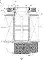
- Fig. 2 shows the filter element 3 from Fig. 1 isolated and in a section perpendicular to that in Fig. 1 illustrated level.
- Fig. 3 shows the filter element 3 from Fig. 1 and 2 in a perspective view from diagonally above. Based on Fig. 2 and 3 the structure of the collar 14 is explained in more detail below.
- the collar 14 has, for example, two elongated holes 22 each extending in the circumferential direction.
- the elongated holes 22 each form through openings through the collar 14 in the radial direction.
- the elongated holes 22 are, as in Fig. 2 to be seen, each closed by a second filter medium 23.
- the second filter media 23 are each injected into the collar 14. While the first filter medium 6 is made of a hydrophilic material, for example paper, the second filter media 23 are each made of a hydrophobic material. For this purpose, the second filter media 23 can be made of PTFE.
- the elongated holes 22 and thus the second filter media 23 are arranged (geodetically) higher than the first filter medium 6 in the illustrated operating position of the filter element 3.
- the filter element 3 has a first compensation element 24.
- the compensation element 24 is composed of a radial section 25 and an axial section 26.
- the radial section 25 rests on the top side of the end disk 5 and can be positively connected to it with the aid of pegs 27.
- the axial section 26 extends parallel to the collar 14, so that an annular gap 28 results in which a stub 31 of the housing 2 that forms the connection opening 15 is received, see FIG Fig. 1 .
- two channels 32 in the form of grooves are formed in the first compensation element 24, each of which extends radially towards the elongated holes 22 or the second filter media 23.
- a respective channel 23 is delimited on the underside by the upper end plate 5.
- the lower end plate 4 can, as for example in Fig. 1 shown have an opening 33.
- a cross 34 is arranged so that the opening 33 in Fig. 1 can only be hinted at.
- the cross 34 protects a third, optionally provided filter medium 35 from manual damage.
- the third filter medium 35 is arranged on the inside with respect to the cross 34, ie on the side of the interior 21.
- the opening 33 is closed by the third filter medium 35.
- the third filter medium 35 is also made hydrophilic according to the exemplary embodiment.
- the third filter medium 35 can be formed from a polyamide fleece.
- the third filter medium 35 is connected to the central tube 11, for example by injection-molding around the third filter medium 35.
- the edge region 36 of the third filter medium 35 is welded all the way around to an edge region 37 of the end disk 4 that delimits the opening 33.
- the filter media 6, 23 and 35 subdivide the filter device 1 into a raw side 41 and a clean side 42.
- liquid to be cleaned in particular urea solution, which when the filter device 1 is in operation, for example via a connection 43 (see Fig. 1 ) is supplied and essentially only flows through the first filter medium 6 and is cleaned in the process.
- the liquid thus reaches the clean side 42 and is fed there, for example, to an exhaust line of the motor vehicle.
- a pump for applying a vacuum to the filter element 3 or to its interior 21 can be provided on the clean side 42.
- the application of the vacuum causes the liquid to outgas and thus gas to accumulate in a (geodetically) high area of the filter device 2.
- the first filter medium 6 is essentially impenetrable for the gas, since the latter soaks up the liquid and thus forms a barrier.
- the second filter media 23, on the other hand, repel the liquid and are permeable to the gases. Gas on the raw side 41 can thus be fed through the channels 32 to the elongated holes 22 or the filter media 23, where it can pass through the filter media 23 in the form of small bubbles and be fed to the exhaust line in a harmless manner.
- the operating pressure difference which is applied to the filter media 6, 23, 35 is selected, for example, in a range between 0 and 0.7 bar (vacuum operation).
- the first filter medium 6 (and possibly the third filter medium 35) is, for example, liquid-permeable above a pressure difference of 0 bar, while the second filter media 23 only become liquid-permeable from a pressure of, for example, 1.0 bar. This then leads to the effect that when the filter device 1 is in operation, liquid only flows through the first filter medium 6 (and possibly through the third filter medium 35, although due to its design only very little liquid flows through it) and gas flows through the second filter media 23 delivered through the opening 17 become.
- the filter element 3 can have a second compensation element 44 below the lower end plate 4.
- the second compensation element 44 can also be formed from EPDM. If the filter device 1 is exposed to very cold conditions, for example in winter, the liquid, in particular the urea solution, in the housing 2 can freeze. Freezing takes place in the in Fig. 1 direction indicated by several arrows from the outside to the inside instead.
- the compensation bodies 24, 44 are designed to accommodate a volume of liquid that increases when the liquid, in particular the urea solution, freezes. In addition, it can be provided that a residual liquid 45 freezes last due to the isolator effect of the compensation element 44.
- a pressure build-up which is associated with freezing of the residual liquid 45 and could damage the filter element 3, is avoided in that the residual liquid 45 can flow through the third filter medium 35 into a gap 46 between the end plate 4 and the compensation element 44.
- the compensation element 44 can, for example, lie directly against the end disk 4, as in FIG Fig. 1 shown.
- the gap 46 is then gradually formed as the residual liquid 45 flows out through the third filter medium 35.
- the above-mentioned principle is also applicable to oils or oil-based liquids.
- the first filter medium 6 is oleophilic and the second filter medium 23 is oleophobic.
Landscapes
- Chemical & Material Sciences (AREA)
- Chemical Kinetics & Catalysis (AREA)
- Exhaust Gas After Treatment (AREA)
- Filtration Of Liquid (AREA)
Description
Die vorliegende Erfindung bezieht sich auf ein Filterelement zum Filtern eines Fluids, insbesondere einer Harnstofflösung, sowie auf eine Filtereinrichtung, insbesondere eine Harnstofffiltereinrichtung.The present invention relates to a filter element for filtering a fluid, in particular a urea solution, and to a filter device, in particular a urea filter device.
Beispielsweise finden bei der Abgasbehandlung in Kraftfahrzeugen zur Reduzierung von Stickoxidemission Harnstofflösungen Verwendung. Harnstofflösung wird dabei über Düsen im Abgasstrang eingespritzt. Insbesondere um ein Verstopfen der Düsen zu verhindern, muss die Harnstofflösung gefiltert werden. Oft wird ein zur Filtration einer Harnstofflösung geeigneter Filter auch Harnstofffilter genannt.For example, urea solutions are used in exhaust gas treatment in motor vehicles to reduce nitrogen oxide emissions. Urea solution is injected through nozzles in the exhaust system. In particular, to prevent the nozzles from clogging, the urea solution must be filtered. A filter suitable for filtering a urea solution is often also called a urea filter.
Zum Filtern der Harnstofflösung ist es bekannt, ein Filterelement zu verwenden, welches saugseitig mit Vakuum oder Unterdruck appliziert oder beaufschlagt wird. Das Vakuum bedingt ein Ausgasen der Harnstofflösung, so dass sich im höchsten Bereich des Filterelements bzw. einer das Filterelement aufnehmenden Filtereinrichtung Gase ansammeln. Wichtig ist es, die angesammelten Gase in Form kleiner Blasen aus dem Filterelement bzw. der Filtereinrichtung herauszuführen, um die Funktion nachgeordneter Komponenten, insbesondere der erwähnten Düsen, nicht zu stören.To filter the urea solution, it is known to use a filter element which is applied or acted upon on the suction side with a vacuum or negative pressure. The vacuum causes outgassing of the urea solution, so that gases collect in the highest area of the filter element or a filter device accommodating the filter element. It is important to lead the accumulated gases out of the filter element or the filter device in the form of small bubbles in order not to disturb the function of downstream components, in particular the mentioned nozzles.
Aus
In
In
Ein weiterer Aspekt, welchen es bei der Entwicklung von Filterelementen für Harnstofflösung zu berücksichtigen gilt, ist der, dass Harnstofflösungen bei ca. -11°C gefrieren. Hierzu ist es beispielsweise aus der
Auch in
Eine Aufgabe der vorliegenden Erfindung besteht darin, ein verbessertes Filterelement sowie eine verbesserte Filtereinrichtung bereitzustellen. Insbesondere besteht eine Aufgabe der vorliegenden Erfindung darin, das Ansammeln großer Gasblasen in dem Filterelement bzw. in der Filtereinrichtung zumindest zu reduzieren.One object of the present invention is to provide an improved filter element and an improved filter device. In particular, it is an object of the present invention to at least reduce the accumulation of large gas bubbles in the filter element or in the filter device.
Zur Lösung dieser Aufgabe wird ein Filterelement zum Filtern eines Fluids, insbesondere einer Harnstofflösung, nach Anspruch 1 vorgeschlagen. Das Filterelement umfasst ein flüssigkeitsdurchlässiges und gasundurchlässiges, erstes Filtermedium und ein flüssigkeitsundurchlässiges und gasdurchlässiges zweites Filtermedium. Das erste und zweite Filtermedium sind jeweils zwischen einer Roh- und einer Reinseite des Filterelements angeordnet.To achieve this object, a filter element for filtering a fluid, in particular a urea solution, is proposed according to
Das Filterelement umschließt ringförmig einen Innenraum und ist von einer Rohseite zu einer Reinseite parallel durch mindestens das erste und das zweite Filtermedium durchströmbar, die jeweils zwischen der Roh- und einer Reinseite des Filterelements angeordnet sind, wobei das erste Filtermedium flüssigkeitsdurchlässig und gasundurchlässig ist und das zweite Filtermedium flüssigkeitsundurchlässig und gasdurchlässig ist.The filter element surrounds an inner space in a ring shape and can flow through at least the first and the second filter medium in parallel from a raw side to a clean side, which are each arranged between the raw and a clean side of the filter element, the first filter medium being liquid-permeable and gas-impermeable and the second The filter medium is impermeable to liquids and gas-permeable.
Während dem ersten Filtermedium die Aufgabe zukommt, das Fluid, insbesondere die Harnstofflösung, zu reinigen, d.h. insbesondere ungewünschte Partikel aus dieser herauszufiltern, wird mit dem zweiten Filtermedium bezweckt, einen kontinuierlichen Transport von kleinen Gasblasen von der Rohseite zur Reinseite des Filterelements zu bewerkstelligen. Dadurch wird das Ansammeln großer Gasmengen im Filterelement bzw. in einer das Filterelement aufnehmenden Filtereinrichtung verhindert.While the task of the first filter medium is to clean the fluid, in particular the urea solution, i.e. in particular to filter out unwanted particles from it, the second filter medium aims to achieve a continuous transport of small gas bubbles from the raw side to the clean side of the filter element. This prevents large amounts of gas from accumulating in the filter element or in a filter device receiving the filter element.
Das erste Filtermedium ist beispielsweise grundsätzlich gasdurchlässig, wird jedoch im vollgesaugten Zustand durch die Oberflächenspannung des Fluids, insbesondere der Harnstofflösung, gesperrt. Das zweite Filtermedium ist beispielsweise grundsätzlich flüssigkeitsdurchlässig, dies jedoch erst ab einem vorbestimmten Differenzdruck, welcher größer als ein Betriebsdifferenzdruck ist, der an dem zweiten Filtermedium im Betrieb des Filterelements anliegt.The first filter medium is, for example, basically gas-permeable, but is blocked in the fully sucked state by the surface tension of the fluid, in particular the urea solution. The second filter medium is, for example, basically liquid-permeable, but only from a predetermined differential pressure which is greater than an operating differential pressure that is applied to the second filter medium when the filter element is in operation.
Bevorzugt ist das zweite Filtermedium (geodätisch) höher angeordnet als das erste Filtermedium.The second filter medium is preferably arranged (geodetically) higher than the first filter medium.
Das Fluid ist eine Flüssigkeit, insbesondere eine Harnstofflösung.The fluid is a liquid, in particular a urea solution.
Das erste Filtermedium kann beispielsweise als Vlies, Gelege oder Gewebe ausgebildet sein. Weiterhin kann das erste Filtermedium gefaltet, beispielsweise in Form eines Balgs, vorgesehen sein. Ferner kann das erste Filtermedium Papier aufweisen.The first filter medium can for example be designed as a fleece, scrim or fabric. Furthermore, the first filter medium can be provided in a folded manner, for example in the form of a bellows. Furthermore, the first filter medium can comprise paper.
Das zweite Filtermedium kann beispielsweise aus Polytetraflurethylen (PTFE) ausgebildet sein.The second filter medium can be made of polytetrafluoroethylene (PTFE), for example.
Gemäß einer Ausführungsform ist das erste Filtermedium hydrophil oder oleophil und das zweite Filtermedium hydrophob oder oleophob ausgebildet. Dadurch wird erreicht, dass sich das erste Filtermedium mit Wasser (hiervon sind ganz allgemein auch Lösungen in Wasser umfasst) bzw. Öl (hiervon sind ganz allgemein auch Lösungen in Öl umfasst) vollsaugt und so eine Sperrwirkung gegenüber dem Durchtritt von Gasen durch das erste Filtermedium erzeugt wird. Dagegen kann Wasser oder Öl (hier gilt entsprechend auch die Verallgemeinerung hin zu Lösungen in Wasser bzw. in Öl) nicht in das zweite Filtermedium eindringen, so dass dieses durchlässig für einen Durchtritt von Gasen bleibt.According to one embodiment, the first filter medium is hydrophilic or oleophilic and the second filter medium is hydrophobic or oleophobic. This ensures that the first filter medium is soaked with water (this generally also includes solutions in water) or oil (this generally also includes solutions in oil) and thus a barrier effect against the passage of gases through the first filter medium is produced. On the other hand, water or oil (here the generalization towards solutions in water or in oil also applies accordingly) cannot penetrate the second filter medium, so that it remains permeable for gases to pass through.
Gemäß einer weiteren Ausführungsform ist das erste Filtermedium oberhalb eines ersten Differenzdrucks gasundurchlässig und flüssigkeitsdurchlässig und das zweite Filtermedium unterhalb eines zweiten Differenzdrucks gasdurchlässig und flüssigkeitsundurchlässig, wobei der zweite Differenzdruck größer als der erste Differenzdruck ist und ein Betriebsdifferenzdruck, bei welchem das Filterelement betreibbar ist, zwischen dem ersten und dem zweiten Differenzdruck liegt. Dadurch wird erreicht, dass die Flüssigkeit, insbesondere die Harnstofflösung, lediglich durch das erste Filtermedium dringt und von diesem gefiltert wird. Das zweite Filtermedium dagegen bleibt für die Flüssigkeit undurchlässig. Das erste Filtermedium weist dann die erwähnte Sperrwirkung gegenüber Gasen auf, während das zweite Filtermedium die Gase durchlässt, insbesondere in Form kleiner Blasen. Der Betriebsdifferenzdruck liegt vorzugsweise in einem Bereich zwischen 0 und 0,7 bar.According to a further embodiment, the first filter medium is gas-impermeable and liquid-permeable above a first differential pressure and the second filter medium is gas-permeable and liquid-impermeable below a second differential pressure, the second differential pressure being greater than the first differential pressure and an operating differential pressure at which the filter element can be operated between the first and second differential pressures. This ensures that the liquid, in particular the urea solution, only penetrates through the first filter medium and is filtered by the latter. The second filter medium, on the other hand, remains impermeable to the liquid. The first filter medium then has the aforementioned barrier effect against gases, while the second filter medium lets the gases through, in particular in the form of small bubbles. The operating differential pressure is preferably in a range between 0 and 0.7 bar.
In einer Ausführungsform ist vorgesehen, dass das erste Filtermedium ringförmig geschlossen ist und sternförmig gefaltet oder gewickelt den Innenraum des Filterelements umschließt.In one embodiment it is provided that the first filter medium is closed in the shape of a ring and, folded or wound in a star shape, surrounds the interior of the filter element.
Erfindungsgemäß ist an einer oder beiden Stirnseiten des ringförmig geschlossenen ersten Filtermediums eine Endscheibe angeordnet, die zum Abdichten der Stirnfläche des ersten Filtermediums dient. In einer Endscheibe ist bevorzugt ein Anschluss zum Abführen gefilterten Fluids oder Zuführen von zu filterndem Fluid vorgesehen.According to the invention, an end plate is arranged on one or both end faces of the annularly closed first filter medium, which end plate serves to seal the end face of the first filter medium. A connection for discharging filtered fluid or supplying fluid to be filtered is preferably provided in an end disk.
Das zweite Filtermedium ist in einer Öffnung in einer Endscheibe angeordnet. Da die Endscheibe das ringförmige Filtermedium axial abschließt, ist damit das zweite Filtermedium auch an einem axialen Ende bzw. der Stirnseite des durch das ringförmige erste Filtermedium gebildeten Filterkörpers angeordnet. Das Filterelement kann so vertikal in einem Filter verwendet werden, wobei das Ende mit dem zweiten Filtermedium nach oben weist. Im Filter nach oben steigendes Gas kann somit oberhalb des ersten Filtermediums durch das zweite Filtermedium abgeführt werden.The second filter medium is arranged in an opening in an end plate. Since the end disk axially closes off the annular filter medium, the second filter medium is thus also arranged at an axial end or the end face of the filter body formed by the annular first filter medium. The filter element can thus be used vertically in a filter, with the end with the second filter medium facing upwards. Gas rising upwards in the filter can thus be discharged through the second filter medium above the first filter medium.
Gemäß einer weiteren Ausführungsform ist das zweite Filtermedium in einer Öffnung eines von einer Endscheibe abragenden Kragens des Filterelements ausgebildet, welcher einen Anschluss des Filterelements zum Abführen gefilterten Fluids oder Zuführen von zu filterndem Fluid bildet. Dadurch, dass das zweite Filtermedium bzw. die Öffnung, welche das zweite Filtermedium verschließt, in dem Kragen des Filterelements angeordnet ist, ist das zweite Filtermedium (geodätisch) hoch angeordnet. Insbesondere ist die Öffnung bzw. das zweite Filtermedium somit oberhalb des ersten Filtermediums angeordnet. Gas, welches von Haus aus zum (geodätisch) höchsten Punkt wandert, kann so von dem ersten Filtermedium ferngehalten und in unmittelbare Nachbarschaft des zweiten Filtermediums gebracht werden.According to a further embodiment, the second filter medium is formed in an opening of a collar of the filter element which protrudes from an end plate and which forms a connection of the filter element for discharging filtered fluid or supplying fluid to be filtered. Because the second filter medium or the opening which closes the second filter medium is arranged in the collar of the filter element, the second filter medium is (geodetically) arranged high. In particular, the opening or the second filter medium is thus arranged above the first filter medium. Gas that migrates from home to the (geodetically) highest point can thus be kept away from the first filter medium and brought into the immediate vicinity of the second filter medium.
Beispielsweise können auch mehrere Öffnungen vorgesehen sein, welche jeweils von einem zweiten Filtermedium verschlossen sind.For example, several openings can also be provided, each of which is closed by a second filter medium.
Gemäß einer weiteren Ausführungsform ist die Öffnung als Langloch ausgebildet. Dadurch kann eine vergleichsweise große Öffnung geschaffen werden. Das Langloch erstreckt sich vorzugsweise in Umfangsrichtung des Kragens.According to a further embodiment, the opening is designed as an elongated hole. This allows a comparatively large opening to be created. The elongated hole preferably extends in the circumferential direction of the collar.
Gemäß einer weiteren Ausführungsform durchdringt die Öffnung den Kragen radial. Dadurch ist die Öffnung für das Gas leicht erreichbar.According to a further embodiment, the opening penetrates the collar radially. This makes the opening for the gas easily accessible.
Gemäß einer weiteren Ausführungsform ist das zweite Filtermedium in den Kragen eingespritzt. Dies kann im Kunststoffspritzgussverfahren erfolgen. Dadurch ergibt sich ein einfacher Herstellungsprozess.According to a further embodiment, the second filter medium is injected into the collar. This can be done using the plastic injection molding process. This results in a simple manufacturing process.
Gemäß einer weiteren Ausführungsform ist auf der Rohseite ein Kompensationselement derart vorgesehen, dass bei einem Einfrieren des Fluids verbleibendes Restfluid durch das zweite Filtermedium oder ein drittes Filtermedium hindurch in einen Spalt zwischen dem zweiten Filtermedium oder dem dritten Filtermedium und dem Kompensationselement strömt. Dieser Spalt kann von Haus aus vorgesehen sein oder sich erst dadurch ergeben, dass das Kompensationselement zurückweicht, wenn das Restfluid durch das zweite oder dritte Filtermedium auf die Rohseite strömt. Das Kompensationselement weist bevorzugt ein Elastomer auf. Das Kompensationselement kann weiterhin geschlossenporig und/oder geschäumt ausgebildet sein. Die Poren können mit Luft gefüllt sein. Bevorzugt weist das Kompensationselement einen Ethylen-Propylen-DienKautschuk (auch als "EPDM" bezeichnet) und/oder einen hydrierten Acryl-Nitril-Butadien-Kautschuk (auch als "HBNR" bezeichnet) auf. Das Kompensationselement kann in Bezug auf das zweite Filtermedium einen Abstand zwischen 0 und 20 mm, bevorzugt zwischen 0 und 10 mm, aufweisen. Es können mehrere Kompensationselemente vorgesehen sein.According to a further embodiment, a compensation element is provided on the raw side such that when the fluid freezes residual fluid flows through the second filter medium or a third filter medium into a gap between the second filter medium or the third filter medium and the compensation element. This gap can be provided by default or it can only result from the fact that the compensation element recedes when the residual fluid flows through the second or third filter medium onto the raw side. The compensation element preferably has an elastomer. The compensation element can also be designed with closed pores and / or foamed. The pores can be filled with air. The compensation element preferably has an ethylene-propylene-diene rubber (also referred to as “EPDM”) and / or a hydrogenated acrylonitrile-butadiene rubber (also referred to as “HBNR”). The compensation element can have a distance between 0 and 20 mm, preferably between 0 and 10 mm, with respect to the second filter medium. Several compensation elements can be provided.
Gemäß einer weiteren Ausführungsform ist das Kompensationselement als Isolator ausgebildet. Dadurch kann die räumliche Anordnung des noch nicht gefrorenen Restfluids in dem Filterelement derart gesteuert werden, dass sich dieses in einem Bereich angrenzend an das zweite oder dritte Filtermedium auf der Reinseite ansammelt. Die gewünschte Isolatoreigenschaft des Kompensationselements kann beispielsweise dadurch bereitgestellt werden, dass dieses EPDM oder HBNR aufweist.According to a further embodiment, the compensation element is designed as an insulator. As a result, the spatial arrangement of the not yet frozen residual fluid in the filter element can be controlled in such a way that it collects in an area adjacent to the second or third filter medium on the clean side. The desired insulating property of the compensation element can be provided, for example, in that it has EPDM or HBNR.
Gemäß einer weiteren Ausführungsform ist ein Kompensationselement vorgesehen, welches einen die Öffnung mit der Rohseite verbindenden Kanal aufweist. Dadurch wird ein einfacher Transport von Gasen hin zu dem zweiten Filtermedium gewährleistet. Der Kanal kann beispielsweise zwischen dem Kompensationselement und einem weiteren Element, beispielsweise einer oberen Endscheibe des Filterelements, gebildet sein. Alternativ kann der Kanal auch mittels einer Durchgangsöffnung im Kompensationselement selbst gebildet sein.According to a further embodiment, a compensation element is provided which has a channel connecting the opening to the raw side. This ensures a simple transport of gases to the second filter medium. The channel can be formed, for example, between the compensation element and a further element, for example an upper end disk of the filter element. Alternatively, the channel can also be formed by means of a through opening in the compensation element itself.
Gemäß einer weiteren Ausführungsform ist das Filterelement als Harnstofffilterelement ausgebildet.According to a further embodiment, the filter element is designed as a urea filter element.
Weiterhin wird eine Filtereinrichtung, insbesondere eine Harnstofffiltereinrichtung, mit dem erfindungsgemäßen Filterelement vorgeschlagen.Furthermore, a filter device, in particular a urea filter device, with the filter element according to the invention is proposed.
Die Filtereinrichtung kann ein Gehäuse aufweisen, in welchem das Filterelement aufgenommen ist. Beispielsweise kann das Gehäuse einen Anschluss aufweisen, welcher abdichtend mit dem Anschluss des Filterelements verbindbar ist. Insbesondere kann der Kragen des Filterelements in den Anschluss der Filtereinrichtung abdichtend eingeschoben werden.The filter device can have a housing in which the filter element is received. For example, the housing can have a connection which can be connected to the connection of the filter element in a sealing manner. In particular, the collar of the filter element can be pushed sealingly into the connection of the filter device.
Außerdem kann die Filtereinrichtung Mittel, insbesondere eine Pumpe, aufweisen, um das Filterelement auf der Reinseite mit Vakuum zu beaufschlagen.In addition, the filter device can have means, in particular a pump, in order to apply a vacuum to the filter element on the clean side.
Gemäß einer weiteren Ausführungsform ragt der Kragen nach oben. Das heißt, dass das Filterelement in der Filtereinrichtung derart angeordnet bzw. in diese eingesetzt ist, dass der Kragen nach (geodätisch) oben zeigt.According to a further embodiment, the collar protrudes upwards. This means that the filter element is arranged or inserted into the filter device in such a way that the collar points towards (geodetically) upwards.
Weitere mögliche Implementierungen der Erfindung umfassen auch nicht explizit genannte Kombinationen von zuvor oder im Folgenden bezüglich der Ausführungsbeispiele beschriebenen Merkmale oder Ausführungsformen des Filterelements oder der Filtereinrichtung. Dabei wird der Fachmann auch Einzelaspekte als Verbesserungen oder Ergänzungen zu der jeweiligen Grundform der Erfindung hinzufügen oder abändern.Further possible implementations of the invention also include combinations, not explicitly mentioned, of features or embodiments of the filter element or the filter device described above or below with regard to the exemplary embodiments. The person skilled in the art will also add or modify individual aspects as improvements or additions to the respective basic form of the invention.
Weitere Ausgestaltungen der Erfindung sind Gegenstand der Unteransprüche sowie der im Folgenden beschriebenen Ausführungsbeispiele der Erfindung. Im Weiteren wird die Erfindung anhand von Ausführungsbeispielen unter Bezugnahme auf die beigelegten Figuren näher erläutert.Further configurations of the invention are the subject matter of the subclaims and of the exemplary embodiments of the invention described below. The invention is explained in more detail below on the basis of exemplary embodiments with reference to the attached figures.
Es zeigt dabei:
-
Fig. 1 in einer Schnittansicht eine Filtereinrichtung gemäß einer Ausführungsform; -
Fig. 2 ein Filterelement der Filtereinrichtung ausFig. 1 in einer Schnittdarstellung, wobei jedoch der Schnitt durch eine Ebene senkrecht zu der inFig. 1 dargestellten Ebene gezeigt ist; und -
Fig. 3 das Filterelement derFig. 1 und2 in einer perspektivischen Darstellung.
-
Fig. 1 in a sectional view a filter device according to an embodiment; -
Fig. 2 a filter element of the filter deviceFig. 1 in a sectional view, but the section through a plane perpendicular to the inFig. 1 shown plane is shown; and -
Fig. 3 the filter element of theFig. 1 and2 in a perspective view.
In den Figuren bezeichnen gleiche Bezugszeichen gleiche oder funktionsgleiche Elemente, soweit nichts Gegenteiliges angegeben ist.In the figures, the same reference symbols denote the same or functionally identical elements, unless otherwise indicated.
Die Filtereinrichtung 1 kann beispielsweise in einem Kraftfahrzeug vorgesehen sein. Die Filtereinrichtung 1 kann dazu eingerichtet sein, eine Flüssigkeit, insbesondere eine Harnstofflösung, zu reinigen.The
Die Filtereinrichtung 1 umfasst ein Gehäuse 2, in welchem ein Filterelement 3 angeordnet ist. Das Filterelement 3 umfasst eine erste, untere Endscheibe 4 und eine zweite, obere Endscheibe 5. Zwischen den beiden Endscheiben 4, 5 ist ein erstes Filtermedium 6 in Form eines Balgs angeordnet. Der Balg bzw. das erste Filtermedium 6 weist beispielsweise im Querschnitt (senkrecht zur Papierebene) einen ringförmigen Querschnitt auf und ist an seinen gegenüberliegenden Enden mit den Endscheiben 4, 5 fluiddicht verschweißt. In dem von dem ersten Filtermedium 6 umschlossenen Innenraum 7 ist ein Stützkörper in Form eines Mittelrohrs 11 angeordnet. Das Mittelrohr 11 weist radiale Durchbrüche 12 hin zu dem ersten Filtermedium 6 auf. "Radial", "axial" und "in Umfangsrichtung" beziehen sich auf eine Mittelachse 13 des Filterelements 3.The
Von der Endscheibe 5 erstreckt sich ein axialer Kragen 14 des Filterelements 3 in eine Anschlussöffnung 15 des Gehäuses 2 hinein und dichtet gegen diese, beispielsweise mittels eines O-Rings 16 außenseitig ab. Das Filterelement 3 ist lösbar in der Anschlussöffnung 15 befestigt und kann bei Bedarf ausgetauscht werden. Der Kragen 14 weist eine Öffnung 17 auf, welche mit dem Inneren 21 des Mittelrohrs 11 flüssigkeitsleitend in Verbindung steht.An
Der Kragen 14 weist beispielsweise zwei, sich jeweils in Umfangsrichtung erstreckende Langlöcher 22 auf. Die Langlöcher 22 bilden jeweils Durchgangsöffnungen durch den Kragen 14 in radialer Richtung. Die Langlöcher 22 sind, wie in
Weiterhin weist das Filterelement 3 ein erstes Kompensationselement 24 auf. Das Kompensationselement 24 setzt sich aus einem radialen Abschnitt 25 und einem axialen Abschnitt 26 zusammen. Der radiale Abschnitt 25 liegt auf der Endscheibe 5 oberseitig auf und kann mit Hilfe von Zapfen 27 mit dieser formschlüssig verbunden sein. Der axiale Abschnitt 26 erstreckt sich parallel zu dem Kragen 14, so dass sich ein Ringspalt 28 ergibt, in dem ein die Anschlussöffnung 15 ausbildender Stutzen 31 des Gehäuses 2 aufgenommen ist, siehe
Wie in
Die untere Endscheibe 4 kann, wie beispielsweise in
Die Filtermedien 6, 23 und 35 unterteilen die Filtereinrichtung 1 in eine Rohseite 41 und eine Reinseite 42. Auf der Rohseite 41 befindet sich zu reinigende Flüssigkeit, insbesondere Harnstofflösung, welche im Betrieb der Filtereinrichtung 1 beispielsweise über einen Anschluss 43 (siehe
Das Anlegen des Vakuums führt dazu, dass die Flüssigkeit ausgast und sich damit Gas in einem (geodätisch) hohen Bereich der Filtereinrichtung 2 ansammelt. Das erste Filtermedium 6 ist dabei im Wesentlichen für das Gas undurchdringbar, da sich dieses mit der Flüssigkeit vollsaugt und damit eine Barriere bildet. Die zweiten Filtermedien 23 dagegen weisen die Flüssigkeit ab und sind für die Gase durchlässig. Gas auf der Rohseite 41 kann so durch die Kanäle 32 den Langlöchern 22 bzw. den Filtermedien 23 zugeführt werden und dort in Form von kleinen Blasen durch die Filtermedien 23 hindurch treten und dem Abgasstrang in unschädlicher Weise zugeführt werden. Die Betriebsdruckdifferenz, welche an die Filtermedien 6, 23, 35 angelegt wird, ist beispielsweise in einem Bereich zwischen 0 und 0,7 bar (Vakuumbetrieb) gewählt. Das erste Filtermedium 6 (und gegebenenfalls das dritte Filtermedium 35) ist beispielsweise oberhalb einer Druckdifferenz von 0 bar flüssigkeitsdurchlässig, während die zweiten Filtermedien 23 erst ab einem Druck von beispielsweise 1,0 bar flüssigkeitsdurchlässig werden. Dies führt dann zu dem Effekt, dass im Betrieb der Filtereinrichtung 1 Flüssigkeit lediglich durch das erste Filtermedium 6 (und gegebenenfalls durch das dritte Filtermedium 35, wobei jedoch auf Grund seiner Auslegung nur sehr wenig Flüssigkeit durch dieses strömt) strömt und Gas über die zweiten Filtermedien 23 über die Öffnung 17 abgegeben werden.The application of the vacuum causes the liquid to outgas and thus gas to accumulate in a (geodetically) high area of the
Zusätzlich zu dem ersten Kompensationselement 24 kann das Filterelement 3 ein zweites Kompensationselement 44 unterhalb der unteren Endscheibe 4 aufweisen. Das zweite Kompensationselement 44 kann ebenfalls aus EPDM gebildet sein. Ist die Filtereinrichtung 1 beispielsweise im Winter sehr kalten Bedingungen ausgesetzt, so kann es zu einem Gefrieren der Flüssigkeit, insbesondere der Harnstofflösung, in dem Gehäuse 2 kommen. Das Gefrieren findet in der in
Genauso könnte auch vorgesehen sein, dass beim Gefrieren eine Restflüssigkeit 47 nach und nach durch die zweiten Filtermedien 23 in einen Ringspalt 51 zwischen dem Kompensationskörper 24 und dem Kragen 14, siehe
Das vorstehend erwähnte Prinzip ist auch auf Öle oder auf Öl basierenden Flüssigkeiten anwendbar. In diesem Fall ist das erste Filtermedium 6 oleophil und das zweite Filtermedium 23 oleophob ausgebildet.The above-mentioned principle is also applicable to oils or oil-based liquids. In this case, the
Claims (13)
- Filter element (3) for filtering a liquid, in particular an urea solution, wherein the filter element annularly encloses an interior space and can be flowed through from a raw side (41) to a clean side (42) in parallel through at least a first (6) and a second (23) filter medium which are each disposed between the raw side and the clean side (41, 42) of the filter element (3), wherein the first filter medium (6) is liquid-permeable and gas-impermeable and the second filter medium (23) is liquid-impermeable and gas-permeable, and wherein the first filter medium (6) features an end disc (5) on one or both front faces and the second filter medium (23) is disposed in an opening (22) in an end disc (5).
- Filter element according to claim 1, wherein the first filter medium (6) is hydrophilic or oleophilic and the second filter medium (23) is hydrophobic or oleophobic.
- Filter element according to claim 1 or 2, wherein the first filter medium (6) is gas-impermeable and liquid-permeable above a first differential pressure and the second filter medium (23) is gas-permeable and liquid-impermeable below a second differential pressure, wherein the second differential pressure is higher than the first differential pressure and an operating differential pressure, which allows the filter element (3) to be operable, is situated between the first and the second differential pressure.
- Filter element according to one of the preceding claims, wherein the first filter medium (6) is annularly closed and surrounds the interior space in a star-shape folded or wound manner.
- Filter element according to one of the preceding claims, wherein the second filter medium (23) is realized in an opening (22) of a collar (14) of the filter element (3) projecting from an end disc (5), said collar forming a connection of the filter element (3) for discharging filtered fluid or supplying fluid to be filtered.
- Filter element according to one of the preceding claims, wherein the opening (22) is designed as long hole.
- Filter element according to claim 5 or 6, wherein the opening (22) radially penetrates the collar (14).
- Filter element according to one of the claims 1 to 5, wherein the second filter element (23) is injected into the end disc (5) or the collar (14).
- Filter element according to one of the claims 1 to 5, wherein a compensation element (24, 44) is provided on the raw side (41) in such a way that, when the fluid is freezing up, remaining residual fluid (45, 47) flows through the second filter medium (23) or a third filter medium (35) into a gap (46, 51) between the second filter medium (23) or the third filter medium (35) and the compensation element (24, 44).
- Filter element according to one of the claims 1 to 6, wherein a compensation element (24) is provided which features a conduit (32) connecting the opening (22) to the raw side (41).
- Filter element according to one of the claims 1 to 10, wherein the filter element (3) is designed as urea filter element.
- Filtering device (1), in particular urea filtering device, having a filter element (3) according to one of the claims 1 to 11.
- Filtering device according to claim 12, wherein the second filter medium (23) is realized in an opening of a collar (14) of the filter element (3) projecting from an end disc (5), said collar forming a connection of the filter element (3) for discharging filtered fluid or supplying fluid to be filtered, wherein the collar (14) projects upwards, in particular away from the first filter medium (6).
Applications Claiming Priority (2)
| Application Number | Priority Date | Filing Date | Title |
|---|---|---|---|
| DE102012017140.4A DE102012017140B4 (en) | 2012-08-30 | 2012-08-30 | Filter element and filter device |
| PCT/EP2013/066181 WO2014032902A1 (en) | 2012-08-30 | 2013-08-01 | Filter element and filter device |
Publications (2)
| Publication Number | Publication Date |
|---|---|
| EP2890472A1 EP2890472A1 (en) | 2015-07-08 |
| EP2890472B1 true EP2890472B1 (en) | 2021-07-07 |
Family
ID=48948400
Family Applications (1)
| Application Number | Title | Priority Date | Filing Date |
|---|---|---|---|
| EP13745821.2A Active EP2890472B1 (en) | 2012-08-30 | 2013-08-01 | Filter element and filter device |
Country Status (5)
| Country | Link |
|---|---|
| US (1) | US9731224B2 (en) |
| EP (1) | EP2890472B1 (en) |
| CN (1) | CN104582811B (en) |
| DE (1) | DE102012017140B4 (en) |
| WO (1) | WO2014032902A1 (en) |
Families Citing this family (15)
| Publication number | Priority date | Publication date | Assignee | Title |
|---|---|---|---|---|
| DE102012222943B4 (en) | 2012-12-12 | 2022-01-13 | Robert Bosch Gmbh | Filter element, filter device, tank device and method for manufacturing and commissioning |
| DE102014013852A1 (en) | 2014-09-24 | 2016-03-24 | Mann + Hummel Gmbh | Filter element, filter and filter system with return bypass |
| ES2793941T3 (en) | 2015-01-06 | 2020-11-17 | A L Filter Co Ltd | Freeze resistant liquid filter |
| US10914228B2 (en) | 2016-11-15 | 2021-02-09 | Cummins Inc. | Waste heat recovery with active coolant pressure control system |
| DE102017203796B4 (en) | 2017-03-08 | 2021-03-18 | Robert Bosch Gmbh | Liquid filter with a displacement body and filter cartridge with a displacement body |
| CN113476924B (en) * | 2017-04-06 | 2023-04-07 | 佛山市顺德区美的饮水机制造有限公司 | Composite filter element and water purification equipment |
| CN108793301A (en) * | 2017-05-03 | 2018-11-13 | 杭州大立过滤设备有限公司 | A hydrophilic-hydrophobic Integral filter element |
| US11766631B2 (en) * | 2017-09-19 | 2023-09-26 | C.C. Jensen A/S | Internal continuous air bypass |
| DE102017011279A1 (en) * | 2017-12-07 | 2019-06-13 | Mann+Hummel Gmbh | Round filter element of a filter for urea-water solution and filter |
| US10411380B1 (en) * | 2018-05-24 | 2019-09-10 | Microsoft Technology Licensing, Llc | Connectors with liquid metal and gas permeable plugs |
| CN108952902A (en) * | 2018-07-17 | 2018-12-07 | 山东艾泰克环保科技股份有限公司 | A kind of diesel engine SCR system injection apparatus anti-blocking mechanism |
| US11344826B2 (en) * | 2019-04-03 | 2022-05-31 | Caterpillar Inc. | Machine fluid system having filter protector for sock filter in manifold tube assembly |
| CN114555211B (en) * | 2019-06-25 | 2024-05-31 | 唐纳森公司 | Filter element end cap with shroud |
| CN112237770B (en) * | 2019-07-16 | 2024-01-05 | 上海索菲玛汽车滤清器有限公司 | Filter cartridge with compensation device |
| DE102020131655A1 (en) | 2020-11-30 | 2022-06-02 | Airbus Operations Gmbh | Filter device for an oil containing device in a vehicle |
Family Cites Families (10)
| Publication number | Priority date | Publication date | Assignee | Title |
|---|---|---|---|---|
| DE3304951A1 (en) | 1983-02-12 | 1984-08-16 | Akzo Gmbh, 5600 Wuppertal | DEVICE FOR FILTERING A LIQUID |
| DE59610112D1 (en) * | 1995-11-10 | 2003-03-13 | Mahle Filtersysteme Gmbh | Filters for liquid flowing in a closed container |
| DE19905645C1 (en) | 1999-02-11 | 2000-10-26 | Sartorius Gmbh | Filter attachment for vacuum filtration |
| DE19939970B4 (en) * | 1999-08-24 | 2006-11-16 | Schuler Pressen Gmbh & Co. Kg | Device for filtering oil and separating air from oil in hydraulic systems |
| EP1218082B1 (en) * | 1999-09-17 | 2003-06-04 | Mykrolis Corporation | Process and filter for filtering a slurry |
| DE10345818A1 (en) | 2003-09-30 | 2005-04-28 | Boehringer Ingelheim Micropart | Method and device for separating and removing gas bubbles from liquids |
| DE102009023951B3 (en) | 2009-06-04 | 2011-01-05 | Mann + Hummel Gmbh | Filter device for liquid filtration |
| DE102009061063B4 (en) * | 2009-06-04 | 2013-09-12 | Mann + Hummel Gmbh | Filter device for liquid filtration |
| US20110088662A1 (en) * | 2009-10-20 | 2011-04-21 | Eaton Corporation | Method of packaging a membrane for use in a venting valve |
| CN102596355A (en) * | 2009-11-12 | 2012-07-18 | 唐纳森公司 | Liquid filter construction for freezing environments |
-
2012
- 2012-08-30 DE DE102012017140.4A patent/DE102012017140B4/en not_active Expired - Fee Related
-
2013
- 2013-08-01 WO PCT/EP2013/066181 patent/WO2014032902A1/en not_active Ceased
- 2013-08-01 CN CN201380045089.7A patent/CN104582811B/en active Active
- 2013-08-01 EP EP13745821.2A patent/EP2890472B1/en active Active
-
2015
- 2015-02-27 US US14/634,135 patent/US9731224B2/en active Active
Non-Patent Citations (1)
| Title |
|---|
| None * |
Also Published As
| Publication number | Publication date |
|---|---|
| WO2014032902A1 (en) | 2014-03-06 |
| CN104582811B (en) | 2018-04-06 |
| EP2890472A1 (en) | 2015-07-08 |
| DE102012017140B4 (en) | 2016-04-07 |
| US9731224B2 (en) | 2017-08-15 |
| US20150165344A1 (en) | 2015-06-18 |
| DE102012017140A1 (en) | 2014-03-06 |
| CN104582811A (en) | 2015-04-29 |
Similar Documents
| Publication | Publication Date | Title |
|---|---|---|
| EP2890472B1 (en) | Filter element and filter device | |
| EP3525913B1 (en) | Round filter element, in particular for gas filtration | |
| EP3004620B1 (en) | Filter element | |
| EP2222382A1 (en) | Filter device, especially liquid filter | |
| EP2682172A2 (en) | Filter apparatus and filter element for such a filter apparatus | |
| EP2579958B1 (en) | Filter device, in particular liquid filter | |
| WO2018072928A1 (en) | Filter device and round filter element, in particular for gas filtration | |
| EP2865433A2 (en) | Filter element and filter system for a liquid medium, particularly diesel fuel | |
| EP2471587A1 (en) | Fuel filter | |
| WO2018202809A1 (en) | Filter element for liquid filtration | |
| WO2013092010A2 (en) | Filter element, filter device and method | |
| EP2808071B1 (en) | Filter device, in particular for an automotive car | |
| DE102006029108A1 (en) | Controlling flow of a liquid stream, especially in fuel or oil filter, comprises passing first stream through unit and exerting pressure on membrane to release second stream that bypasses unit | |
| WO2015018779A1 (en) | Water separating screen for a filter element in a liquid filter | |
| EP2886181B1 (en) | Liquid filter | |
| WO2015082117A1 (en) | Filter device comprising an adapter piece | |
| DE102013001843A1 (en) | Filter element for filtering e.g. urea, has hydrophilic and hydrophobic portions that are in fluid communication with outlets for taking out filtered liquid from filter element and for leading gas from filter element respectively | |
| EP3000520B1 (en) | Filter insert | |
| DE102009048588A1 (en) | Filter device, in particular for liquid filtration in internal combustion engines | |
| EP3160614B1 (en) | Filter system and liquid filter | |
| DE102005058109B4 (en) | Use of a filter unit with a predetermined breaking point | |
| DE102005043968A1 (en) | Filter device with a passage opening for the discharge of air | |
| DE102013004865B4 (en) | Filter device with an annular filter element | |
| EP4115964B1 (en) | Filter device | |
| DE102012012543B4 (en) | A filter assembly |
Legal Events
| Date | Code | Title | Description |
|---|---|---|---|
| PUAI | Public reference made under article 153(3) epc to a published international application that has entered the european phase |
Free format text: ORIGINAL CODE: 0009012 |
|
| 17P | Request for examination filed |
Effective date: 20150204 |
|
| AK | Designated contracting states |
Kind code of ref document: A1 Designated state(s): AL AT BE BG CH CY CZ DE DK EE ES FI FR GB GR HR HU IE IS IT LI LT LU LV MC MK MT NL NO PL PT RO RS SE SI SK SM TR |
|
| AX | Request for extension of the european patent |
Extension state: BA ME |
|
| DAX | Request for extension of the european patent (deleted) | ||
| STAA | Information on the status of an ep patent application or granted ep patent |
Free format text: STATUS: EXAMINATION IS IN PROGRESS |
|
| 17Q | First examination report despatched |
Effective date: 20180209 |
|
| RAP1 | Party data changed (applicant data changed or rights of an application transferred) |
Owner name: MANN+HUMMEL GMBH |
|
| GRAP | Despatch of communication of intention to grant a patent |
Free format text: ORIGINAL CODE: EPIDOSNIGR1 |
|
| STAA | Information on the status of an ep patent application or granted ep patent |
Free format text: STATUS: GRANT OF PATENT IS INTENDED |
|
| GRAJ | Information related to disapproval of communication of intention to grant by the applicant or resumption of examination proceedings by the epo deleted |
Free format text: ORIGINAL CODE: EPIDOSDIGR1 |
|
| STAA | Information on the status of an ep patent application or granted ep patent |
Free format text: STATUS: EXAMINATION IS IN PROGRESS |
|
| INTG | Intention to grant announced |
Effective date: 20201222 |
|
| GRAP | Despatch of communication of intention to grant a patent |
Free format text: ORIGINAL CODE: EPIDOSNIGR1 |
|
| STAA | Information on the status of an ep patent application or granted ep patent |
Free format text: STATUS: GRANT OF PATENT IS INTENDED |
|
| INTC | Intention to grant announced (deleted) | ||
| INTG | Intention to grant announced |
Effective date: 20210209 |
|
| GRAJ | Information related to disapproval of communication of intention to grant by the applicant or resumption of examination proceedings by the epo deleted |
Free format text: ORIGINAL CODE: EPIDOSDIGR1 |
|
| STAA | Information on the status of an ep patent application or granted ep patent |
Free format text: STATUS: EXAMINATION IS IN PROGRESS |
|
| GRAP | Despatch of communication of intention to grant a patent |
Free format text: ORIGINAL CODE: EPIDOSNIGR1 |
|
| STAA | Information on the status of an ep patent application or granted ep patent |
Free format text: STATUS: GRANT OF PATENT IS INTENDED |
|
| INTC | Intention to grant announced (deleted) | ||
| INTG | Intention to grant announced |
Effective date: 20210408 |
|
| RAP3 | Party data changed (applicant data changed or rights of an application transferred) |
Owner name: MANN+HUMMEL GMBH |
|
| GRAS | Grant fee paid |
Free format text: ORIGINAL CODE: EPIDOSNIGR3 |
|
| GRAA | (expected) grant |
Free format text: ORIGINAL CODE: 0009210 |
|
| STAA | Information on the status of an ep patent application or granted ep patent |
Free format text: STATUS: THE PATENT HAS BEEN GRANTED |
|
| AK | Designated contracting states |
Kind code of ref document: B1 Designated state(s): AL AT BE BG CH CY CZ DE DK EE ES FI FR GB GR HR HU IE IS IT LI LT LU LV MC MK MT NL NO PL PT RO RS SE SI SK SM TR |
|
| REG | Reference to a national code |
Ref country code: GB Ref legal event code: FG4D Free format text: NOT ENGLISH |
|
| REG | Reference to a national code |
Ref country code: AT Ref legal event code: REF Ref document number: 1408001 Country of ref document: AT Kind code of ref document: T Effective date: 20210715 |
|
| REG | Reference to a national code |
Ref country code: DE Ref legal event code: R096 Ref document number: 502013015820 Country of ref document: DE |
|
| REG | Reference to a national code |
Ref country code: IE Ref legal event code: FG4D Free format text: LANGUAGE OF EP DOCUMENT: GERMAN |
|
| REG | Reference to a national code |
Ref country code: LT Ref legal event code: MG9D |
|
| REG | Reference to a national code |
Ref country code: NL Ref legal event code: MP Effective date: 20210707 |
|
| PG25 | Lapsed in a contracting state [announced via postgrant information from national office to epo] |
Ref country code: HR Free format text: LAPSE BECAUSE OF FAILURE TO SUBMIT A TRANSLATION OF THE DESCRIPTION OR TO PAY THE FEE WITHIN THE PRESCRIBED TIME-LIMIT Effective date: 20210707 Ref country code: SE Free format text: LAPSE BECAUSE OF FAILURE TO SUBMIT A TRANSLATION OF THE DESCRIPTION OR TO PAY THE FEE WITHIN THE PRESCRIBED TIME-LIMIT Effective date: 20210707 Ref country code: PT Free format text: LAPSE BECAUSE OF FAILURE TO SUBMIT A TRANSLATION OF THE DESCRIPTION OR TO PAY THE FEE WITHIN THE PRESCRIBED TIME-LIMIT Effective date: 20211108 Ref country code: NO Free format text: LAPSE BECAUSE OF FAILURE TO SUBMIT A TRANSLATION OF THE DESCRIPTION OR TO PAY THE FEE WITHIN THE PRESCRIBED TIME-LIMIT Effective date: 20211007 Ref country code: RS Free format text: LAPSE BECAUSE OF FAILURE TO SUBMIT A TRANSLATION OF THE DESCRIPTION OR TO PAY THE FEE WITHIN THE PRESCRIBED TIME-LIMIT Effective date: 20210707 Ref country code: NL Free format text: LAPSE BECAUSE OF FAILURE TO SUBMIT A TRANSLATION OF THE DESCRIPTION OR TO PAY THE FEE WITHIN THE PRESCRIBED TIME-LIMIT Effective date: 20210707 Ref country code: ES Free format text: LAPSE BECAUSE OF FAILURE TO SUBMIT A TRANSLATION OF THE DESCRIPTION OR TO PAY THE FEE WITHIN THE PRESCRIBED TIME-LIMIT Effective date: 20210707 Ref country code: FI Free format text: LAPSE BECAUSE OF FAILURE TO SUBMIT A TRANSLATION OF THE DESCRIPTION OR TO PAY THE FEE WITHIN THE PRESCRIBED TIME-LIMIT Effective date: 20210707 Ref country code: LT Free format text: LAPSE BECAUSE OF FAILURE TO SUBMIT A TRANSLATION OF THE DESCRIPTION OR TO PAY THE FEE WITHIN THE PRESCRIBED TIME-LIMIT Effective date: 20210707 Ref country code: BG Free format text: LAPSE BECAUSE OF FAILURE TO SUBMIT A TRANSLATION OF THE DESCRIPTION OR TO PAY THE FEE WITHIN THE PRESCRIBED TIME-LIMIT Effective date: 20211007 |
|
| PG25 | Lapsed in a contracting state [announced via postgrant information from national office to epo] |
Ref country code: PL Free format text: LAPSE BECAUSE OF FAILURE TO SUBMIT A TRANSLATION OF THE DESCRIPTION OR TO PAY THE FEE WITHIN THE PRESCRIBED TIME-LIMIT Effective date: 20210707 Ref country code: LV Free format text: LAPSE BECAUSE OF FAILURE TO SUBMIT A TRANSLATION OF THE DESCRIPTION OR TO PAY THE FEE WITHIN THE PRESCRIBED TIME-LIMIT Effective date: 20210707 Ref country code: GR Free format text: LAPSE BECAUSE OF FAILURE TO SUBMIT A TRANSLATION OF THE DESCRIPTION OR TO PAY THE FEE WITHIN THE PRESCRIBED TIME-LIMIT Effective date: 20211008 |
|
| REG | Reference to a national code |
Ref country code: CH Ref legal event code: PL |
|
| REG | Reference to a national code |
Ref country code: DE Ref legal event code: R097 Ref document number: 502013015820 Country of ref document: DE |
|
| REG | Reference to a national code |
Ref country code: BE Ref legal event code: MM Effective date: 20210831 |
|
| PG25 | Lapsed in a contracting state [announced via postgrant information from national office to epo] |
Ref country code: LI Free format text: LAPSE BECAUSE OF NON-PAYMENT OF DUE FEES Effective date: 20210831 Ref country code: DK Free format text: LAPSE BECAUSE OF FAILURE TO SUBMIT A TRANSLATION OF THE DESCRIPTION OR TO PAY THE FEE WITHIN THE PRESCRIBED TIME-LIMIT Effective date: 20210707 Ref country code: CH Free format text: LAPSE BECAUSE OF NON-PAYMENT OF DUE FEES Effective date: 20210831 |
|
| PLBE | No opposition filed within time limit |
Free format text: ORIGINAL CODE: 0009261 |
|
| STAA | Information on the status of an ep patent application or granted ep patent |
Free format text: STATUS: NO OPPOSITION FILED WITHIN TIME LIMIT |
|
| PG25 | Lapsed in a contracting state [announced via postgrant information from national office to epo] |
Ref country code: SM Free format text: LAPSE BECAUSE OF FAILURE TO SUBMIT A TRANSLATION OF THE DESCRIPTION OR TO PAY THE FEE WITHIN THE PRESCRIBED TIME-LIMIT Effective date: 20210707 Ref country code: SK Free format text: LAPSE BECAUSE OF FAILURE TO SUBMIT A TRANSLATION OF THE DESCRIPTION OR TO PAY THE FEE WITHIN THE PRESCRIBED TIME-LIMIT Effective date: 20210707 Ref country code: RO Free format text: LAPSE BECAUSE OF FAILURE TO SUBMIT A TRANSLATION OF THE DESCRIPTION OR TO PAY THE FEE WITHIN THE PRESCRIBED TIME-LIMIT Effective date: 20210707 Ref country code: MC Free format text: LAPSE BECAUSE OF FAILURE TO SUBMIT A TRANSLATION OF THE DESCRIPTION OR TO PAY THE FEE WITHIN THE PRESCRIBED TIME-LIMIT Effective date: 20210707 Ref country code: LU Free format text: LAPSE BECAUSE OF NON-PAYMENT OF DUE FEES Effective date: 20210801 Ref country code: EE Free format text: LAPSE BECAUSE OF FAILURE TO SUBMIT A TRANSLATION OF THE DESCRIPTION OR TO PAY THE FEE WITHIN THE PRESCRIBED TIME-LIMIT Effective date: 20210707 Ref country code: CZ Free format text: LAPSE BECAUSE OF FAILURE TO SUBMIT A TRANSLATION OF THE DESCRIPTION OR TO PAY THE FEE WITHIN THE PRESCRIBED TIME-LIMIT Effective date: 20210707 Ref country code: AL Free format text: LAPSE BECAUSE OF FAILURE TO SUBMIT A TRANSLATION OF THE DESCRIPTION OR TO PAY THE FEE WITHIN THE PRESCRIBED TIME-LIMIT Effective date: 20210707 |
|
| 26N | No opposition filed |
Effective date: 20220408 |
|
| PG25 | Lapsed in a contracting state [announced via postgrant information from national office to epo] |
Ref country code: IE Free format text: LAPSE BECAUSE OF NON-PAYMENT OF DUE FEES Effective date: 20210801 Ref country code: BE Free format text: LAPSE BECAUSE OF NON-PAYMENT OF DUE FEES Effective date: 20210831 |
|
| REG | Reference to a national code |
Ref country code: AT Ref legal event code: MM01 Ref document number: 1408001 Country of ref document: AT Kind code of ref document: T Effective date: 20210801 |
|
| PG25 | Lapsed in a contracting state [announced via postgrant information from national office to epo] |
Ref country code: AT Free format text: LAPSE BECAUSE OF NON-PAYMENT OF DUE FEES Effective date: 20210801 |
|
| PG25 | Lapsed in a contracting state [announced via postgrant information from national office to epo] |
Ref country code: HU Free format text: LAPSE BECAUSE OF FAILURE TO SUBMIT A TRANSLATION OF THE DESCRIPTION OR TO PAY THE FEE WITHIN THE PRESCRIBED TIME-LIMIT; INVALID AB INITIO Effective date: 20130801 |
|
| PG25 | Lapsed in a contracting state [announced via postgrant information from national office to epo] |
Ref country code: CY Free format text: LAPSE BECAUSE OF FAILURE TO SUBMIT A TRANSLATION OF THE DESCRIPTION OR TO PAY THE FEE WITHIN THE PRESCRIBED TIME-LIMIT Effective date: 20210707 |
|
| P01 | Opt-out of the competence of the unified patent court (upc) registered |
Effective date: 20230627 |
|
| PG25 | Lapsed in a contracting state [announced via postgrant information from national office to epo] |
Ref country code: MK Free format text: LAPSE BECAUSE OF FAILURE TO SUBMIT A TRANSLATION OF THE DESCRIPTION OR TO PAY THE FEE WITHIN THE PRESCRIBED TIME-LIMIT Effective date: 20210707 |
|
| PG25 | Lapsed in a contracting state [announced via postgrant information from national office to epo] |
Ref country code: MT Free format text: LAPSE BECAUSE OF FAILURE TO SUBMIT A TRANSLATION OF THE DESCRIPTION OR TO PAY THE FEE WITHIN THE PRESCRIBED TIME-LIMIT Effective date: 20210707 |
|
| PGFP | Annual fee paid to national office [announced via postgrant information from national office to epo] |
Ref country code: DE Payment date: 20250820 Year of fee payment: 13 |
|
| PGFP | Annual fee paid to national office [announced via postgrant information from national office to epo] |
Ref country code: IT Payment date: 20250825 Year of fee payment: 13 |
|
| PGFP | Annual fee paid to national office [announced via postgrant information from national office to epo] |
Ref country code: GB Payment date: 20250821 Year of fee payment: 13 |
|
| PGFP | Annual fee paid to national office [announced via postgrant information from national office to epo] |
Ref country code: FR Payment date: 20250829 Year of fee payment: 13 |
|
| PG25 | Lapsed in a contracting state [announced via postgrant information from national office to epo] |
Ref country code: TR Free format text: LAPSE BECAUSE OF FAILURE TO SUBMIT A TRANSLATION OF THE DESCRIPTION OR TO PAY THE FEE WITHIN THE PRESCRIBED TIME-LIMIT Effective date: 20210707 |