EP2865433A2 - Filter element and filter system for a liquid medium, particularly diesel fuel - Google Patents
Filter element and filter system for a liquid medium, particularly diesel fuel Download PDFInfo
- Publication number
- EP2865433A2 EP2865433A2 EP20140188543 EP14188543A EP2865433A2 EP 2865433 A2 EP2865433 A2 EP 2865433A2 EP 20140188543 EP20140188543 EP 20140188543 EP 14188543 A EP14188543 A EP 14188543A EP 2865433 A2 EP2865433 A2 EP 2865433A2
- Authority
- EP
- European Patent Office
- Prior art keywords
- filter
- filter element
- water
- particle
- liquid medium
- Prior art date
- Legal status (The legal status is an assumption and is not a legal conclusion. Google has not performed a legal analysis and makes no representation as to the accuracy of the status listed.)
- Withdrawn
Links
- 239000007788 liquid Substances 0.000 title claims abstract description 23
- 239000002283 diesel fuel Substances 0.000 title claims description 4
- XLYOFNOQVPJJNP-UHFFFAOYSA-N water Substances O XLYOFNOQVPJJNP-UHFFFAOYSA-N 0.000 claims abstract description 70
- 239000002245 particle Substances 0.000 claims abstract description 47
- 239000000446 fuel Substances 0.000 claims description 19
- 239000000835 fiber Substances 0.000 claims description 13
- 238000011144 upstream manufacturing Methods 0.000 claims description 4
- 238000004140 cleaning Methods 0.000 abstract description 4
- 239000012530 fluid Substances 0.000 abstract description 4
- 238000000926 separation method Methods 0.000 description 24
- 239000012535 impurity Substances 0.000 description 9
- 239000000356 contaminant Substances 0.000 description 4
- 238000007789 sealing Methods 0.000 description 4
- 238000002485 combustion reaction Methods 0.000 description 3
- 238000001914 filtration Methods 0.000 description 3
- 230000000717 retained effect Effects 0.000 description 3
- 229920003043 Cellulose fiber Polymers 0.000 description 2
- 230000008021 deposition Effects 0.000 description 2
- 239000012208 gear oil Substances 0.000 description 2
- 238000009434 installation Methods 0.000 description 2
- 239000000314 lubricant Substances 0.000 description 2
- 238000004519 manufacturing process Methods 0.000 description 2
- 239000011148 porous material Substances 0.000 description 2
- 241000978750 Havardia Species 0.000 description 1
- 229920001410 Microfiber Polymers 0.000 description 1
- 230000000712 assembly Effects 0.000 description 1
- 238000000429 assembly Methods 0.000 description 1
- 238000005452 bending Methods 0.000 description 1
- 238000011109 contamination Methods 0.000 description 1
- 239000002657 fibrous material Substances 0.000 description 1
- 230000005484 gravity Effects 0.000 description 1
- 239000010720 hydraulic oil Substances 0.000 description 1
- 238000002347 injection Methods 0.000 description 1
- 239000007924 injection Substances 0.000 description 1
- 239000010687 lubricating oil Substances 0.000 description 1
- 239000003658 microfiber Substances 0.000 description 1
- 229920000098 polyolefin Polymers 0.000 description 1
- 238000000746 purification Methods 0.000 description 1
- 238000009420 retrofitting Methods 0.000 description 1
Images

Classifications
-
- F—MECHANICAL ENGINEERING; LIGHTING; HEATING; WEAPONS; BLASTING
- F02—COMBUSTION ENGINES; HOT-GAS OR COMBUSTION-PRODUCT ENGINE PLANTS
- F02M—SUPPLYING COMBUSTION ENGINES IN GENERAL WITH COMBUSTIBLE MIXTURES OR CONSTITUENTS THEREOF
- F02M37/00—Apparatus or systems for feeding liquid fuel from storage containers to carburettors or fuel-injection apparatus; Arrangements for purifying liquid fuel specially adapted for, or arranged on, internal-combustion engines
- F02M37/22—Arrangements for purifying liquid fuel specially adapted for, or arranged on, internal-combustion engines, e.g. arrangements in the feeding system
- F02M37/24—Arrangements for purifying liquid fuel specially adapted for, or arranged on, internal-combustion engines, e.g. arrangements in the feeding system characterised by water separating means
-
- B—PERFORMING OPERATIONS; TRANSPORTING
- B01—PHYSICAL OR CHEMICAL PROCESSES OR APPARATUS IN GENERAL
- B01D—SEPARATION
- B01D35/00—Filtering devices having features not specifically covered by groups B01D24/00 - B01D33/00, or for applications not specifically covered by groups B01D24/00 - B01D33/00; Auxiliary devices for filtration; Filter housing constructions
- B01D35/005—Filters specially adapted for use in internal-combustion engine lubrication or fuel systems
-
- B—PERFORMING OPERATIONS; TRANSPORTING
- B01—PHYSICAL OR CHEMICAL PROCESSES OR APPARATUS IN GENERAL
- B01D—SEPARATION
- B01D29/00—Filters with filtering elements stationary during filtration, e.g. pressure or suction filters, not covered by groups B01D24/00 - B01D27/00; Filtering elements therefor
- B01D29/11—Filters with filtering elements stationary during filtration, e.g. pressure or suction filters, not covered by groups B01D24/00 - B01D27/00; Filtering elements therefor with bag, cage, hose, tube, sleeve or like filtering elements
- B01D29/13—Supported filter elements
- B01D29/15—Supported filter elements arranged for inward flow filtration
- B01D29/21—Supported filter elements arranged for inward flow filtration with corrugated, folded or wound sheets
-
- B—PERFORMING OPERATIONS; TRANSPORTING
- B01—PHYSICAL OR CHEMICAL PROCESSES OR APPARATUS IN GENERAL
- B01D—SEPARATION
- B01D29/00—Filters with filtering elements stationary during filtration, e.g. pressure or suction filters, not covered by groups B01D24/00 - B01D27/00; Filtering elements therefor
- B01D29/50—Filters with filtering elements stationary during filtration, e.g. pressure or suction filters, not covered by groups B01D24/00 - B01D27/00; Filtering elements therefor with multiple filtering elements, characterised by their mutual disposition
- B01D29/56—Filters with filtering elements stationary during filtration, e.g. pressure or suction filters, not covered by groups B01D24/00 - B01D27/00; Filtering elements therefor with multiple filtering elements, characterised by their mutual disposition in series connection
- B01D29/58—Filters with filtering elements stationary during filtration, e.g. pressure or suction filters, not covered by groups B01D24/00 - B01D27/00; Filtering elements therefor with multiple filtering elements, characterised by their mutual disposition in series connection arranged concentrically or coaxially
-
- B—PERFORMING OPERATIONS; TRANSPORTING
- B01—PHYSICAL OR CHEMICAL PROCESSES OR APPARATUS IN GENERAL
- B01D—SEPARATION
- B01D36/00—Filter circuits or combinations of filters with other separating devices
- B01D36/003—Filters in combination with devices for the removal of liquids
-
- B—PERFORMING OPERATIONS; TRANSPORTING
- B01—PHYSICAL OR CHEMICAL PROCESSES OR APPARATUS IN GENERAL
- B01D—SEPARATION
- B01D2201/00—Details relating to filtering apparatus
- B01D2201/29—Filter cartridge constructions
- B01D2201/291—End caps
- B01D2201/295—End caps with projections extending in a radial outward direction, e.g. for use as a guide, spacing means
-
- B—PERFORMING OPERATIONS; TRANSPORTING
- B01—PHYSICAL OR CHEMICAL PROCESSES OR APPARATUS IN GENERAL
- B01D—SEPARATION
- B01D2201/00—Details relating to filtering apparatus
- B01D2201/40—Special measures for connecting different parts of the filter
- B01D2201/4084—Snap or Seeger ring connecting means
Definitions
- the invention relates to a filter element for a liquid medium, in particular diesel fuel, according to the preamble of patent claim 1 and a filter system with such a filter element.
- a fuel filter system with a filter housing and with a filter element arranged in the filter element has become known, in which the filter element comprises a ring-shaped filter medium which can be flowed through by the fuel in a radial direction of flow to the longitudinal axis of the filter element.
- the filter element has a clean room, which is arranged in the interior of the filter element in the flow direction behind the filter element.
- the clean room is connected to an outlet of the filter element for the filtered liquid medium.
- a Wasserabscheide responded with a Wasserabscheidesieb and the Wasserabscheidesieb upstream in the flow direction Coalescer element serves to separate water from the guided through the filter medium fuel.
- the clean room is fluidly connected via a water outlet opening with a bottom arranged water collecting space of the filter housing.
- the invention has for its object to provide an aforementioned filter element and a filter system with such a filter element, are overcome in the disadvantages of the prior art.
- the object relating to the filter element is achieved by a filter element having the features specified in claim 1 and the object relating to the filter system by a filter system having the features specified in patent claim 10.
- the filter element according to the invention is provided with a particle filter which is arranged in the region of the water outlet opening or between the water outlet opening and the outlet of the filter element.
- the filter element according to the invention on the one hand ensures a reliable separation of water contained in the liquid medium from the liquid medium, as is required for fuels for reliable operation of an internal combustion engine.
- undesired contamination of the liquid medium discharged from the filter element, in particular diesel fuel can be prevented by impurities contained in the water collecting space of a filter housing, even if the filter element is frequently required to be exchanged in practice. This is advantageous for trouble-free operation and the longevity of machines or assemblies operated with the liquid medium. A required in practice, especially in critical applications, cleaning the water collection space is therefore unnecessary in most cases.
- the particle filter is disposed within the Wasserabscheidesiebs.
- the particle filter can thereby be easily inserted into the Wasserabscheidesieb during assembly. Retrofitting existing filter elements is possible. In addition, this can be a large (active) filter surface are provided. Even a higher degree of dirt entry into the clean room of the filter element can be easily filtered out of the liquid medium. It is understood that the particle filter must be coupled on the edge side of components of the filter element such that the liquid medium with the impurities contained therein completely, d. H. without bypassing the particle filter, over the particulate filter is feasible.
- the particle filter may preferably form an additional particle filtration stage to the (main) filter medium.
- it has for this purpose a higher filtration fineness than the upstream (main) filter medium, d. H. small particles that can pass through the (main) filter media are retained at the particulate filter.
- the active filter surface of the particulate filter can be further increased according to the invention, characterized in that the particulate filter is designed as a star-folded bellows.
- the particulate filter is designed as a star-folded bellows.
- a particularly robust mechanical structure of the filter element can be achieved according to the invention in that the particle filter rests on the inside on a central tube.
- the particle filter can thereby also at a high pressure
- the particle filter can be fastened in particular to the sieve element and / or to the central tube by the liquid medium as well as any flow resistance which may be increased by impurities.
- the particle filter can be attached to the sieve element and / or to the central tube to form a mounting unit.
- this filter is advantageously arranged on the outside on a lower end plate of the filter element.
- the particle filter can cover the water outlet opening, in particular in the axial direction. This allows a particularly simple installation of the particulate filter.
- the particulate filter is held by means of an annular holding means on the end plate, which is bolted or latched to the end plate.
- the end plate is preferably integrally formed with a suitable thread or with suitable locking means for the retaining means.
- the particle filter can be formed or comprise in particular fibers, in particular cellulose fibers.
- Other fibers for example of a polyolefin, are conceivable.
- the fibers can be hydrophilic and / or hydrophilic in order to remove water molecules or water droplets in a simplified manner via the particle filter from the separation space.
- the fibers of the particle filter according to the invention preferably have a unidirectional or substantially unidirectional fiber profile. As a result, the removal of water separated from the liquid medium from the clean room can be further improved.
- the filter element may have a coalescing element which is connected upstream of the water separation screen.
- the coalescing element is preferably arranged in the clean room and adjacent to the filter medium.
- the coalescer element can be formed of fibers or comprise fibers. This allows a particularly effective separation of water from the liquid medium to be filtered.
- the filter system according to the invention comprises a filter housing and a filter element arranged in the filter housing, as has been explained above.
- the water outlet opening of the filter element or the clean room is fluidically connected to a bottom-side arranged water collecting space of the filter housing.
- the filter element and the filter system are suitable for many technical applications, such as the fuel treatment for internal combustion engines with or without injection systems or the filtration of lubricants such as gear or hydraulic oil.
- a filter system 10 is shown with a filter housing 12 and with a filter element 14 arranged therein for a liquid medium, in particular for a fuel or lubricant.
- the filter housing 12 has a housing container 16, which is closed by means of a housing cover 16 releasably arranged on the housing cover 18.
- a fuel supply 20 for the fuel to be filtered and an outlet 22 in the form of a fuel discharge for the fuel filtered in the filter system 10 are fastened to the housing cover 18.
- the filter element 14 has a substantially cylindrical cross-section. Between an upper end plate 24 and a lower end plate 26 of the filter element 14 an annularly closed star-folded filter medium 28 is arranged.
- the filter medium 28 flows through from the fuel to be filtered in a direction of flow radially to the longitudinal axis 30 of the filter element 14 from the outside to the inside.
- a separation device 31 for separating fluid impurities contained in the fuel, here water, arranged.
- the separation device 31 comprises a coalescer element 32 and a water separation screen 34, which are arranged one behind the other in the flow direction. Between the coalescing element 32 and the sieve-shaped water separation element 34, a separation chamber 36 is formed.
- the separation chamber 36 serves a gravity following weaning deposited from the fuel deposition products, in particular water molecules or water droplets.
- the separation chamber 36 has a water outlet 38 for the Abscheide area, which is bounded by the lower end plate 26 of the filter element 14.
- the separation products move downward in the direction of and through the water outlet opening 38 into a water-collecting space 40 of the filter housing 12 arranged on the bottom side.
- the water collecting space 40 is connected to the separation chamber 36 via the water outlet opening 38.
- the filter element 14 circumferentially on a circumferential rubber-elastic sealing element 42 which abuts the housing container 16 on the inside wall side sealing.
- the sealing element 42 separates an input side, ie arranged in the flow direction in front of the filter medium 28, Kraftstoffzu Glassspalt 44 with unfiltered and therefore potentially contaminated fuel relative to the water collection chamber 40 of the filter housing 12 sealingly.
- the filter element shown has a particle filter 46 arranged inside the filter element 14 in order to separate the contaminants or particles introduced from the water collection chamber 40 into the separation chamber 36 from the fuel before it is removed from the filter system 10 via the outlet 22.
- the particle filter 46 is thus arranged in the flow direction of the liquid medium behind the Wasserabscheideelement 34.
- the particle filter 46 is embodied as an annularly closed star-folded bellows and can, for example, sealingly abut against the end plates 24, 26 of the filter element 14 or in the radial direction on the water separation element 34 via sealing parts molded onto the end. In order to support the particle filter 46, the particle filter 46 rests against a central tube 47 with its radially inner side.
- a clean room R of the filter system 10 is located after the particle filter 46.
- the particle filter 46 preferably consists of a hydrophilic fiber material and has a larger pore size compared to the filter medium 28.
- the pore size of the particulate filter 46 may in particular be between 50 microns and 200 microns.
- Fig. 2 shows a filter element 14 ', which differs from the in Fig. 1 filter element 14 substantially differs in that the particle filter 46 'in the region of the water outlet opening 38' of the separation chamber 36 'on the outside of the lower end plate 26' of the filter element 14 'is arranged.
- the particle filter 46 ' is disc-shaped.
- the water outlet opening 38 'of the separation chamber 36' is completely covered by the particle filter 46 'in the axial direction.
- an annular holding means 48 which is locked with a locking element 50 of the lower end plate 26'.
- the locking element 50 is integrally formed on the lower end plate 26 ', that is integrally formed with the lower end plate 26'.
- the particle filters 46, 46 ' comprise hydrophilic fibers, for example cellulose fibers, in order to ensure a reliable discharge of the water molecules or water droplets deposited in the separation chamber 36, 36' into the water collecting space 40.
- the fibers may in particular be microfibers. The fibers can do this have unidirectional or substantially unidirectional fiber flow, in order to promote discharge of the separation products from the separation chamber 36, 36 'in the water collecting space 40.
- FIG. 1 shown filter system or in the FIGS. 1 and 2 shown filter elements can also be used for other applications, for example, for the purification of gear or lubricating oil.
- the invention relates to a filter element for cleaning a liquid medium.
- the filter element can be inserted into a filter housing of a filter system and has a filter medium.
- the filter medium is first followed by a Wasserabscheidesieb and then a clean room fluidly.
- the rebounding water on the water separator flows through a water outlet in a water collection chamber of the filter housing.
- the water collection room is therefore fluidly in communication with the clean room.
- dirt particles can get into the water collection chamber.
- a particle filter is arranged between the water collection room and the clean room.
- the invention further relates to a filter system with a filter element described above.
Abstract
Die Erfindung betrifft ein Filterelement (14) zur Reinigung eines Flüssigmediums. Das Filterelement (14) ist in ein Filtergehäuse (12) eines Filtersystems (10) einsetzbar und weist ein Filtermedium (28) auf. Dem Filtermedium (28) ist zunächst ein Wasserabscheidesieb (34) und danach ein Reinraum (R) fluidisch nachgeordnet. Das am Wasserabscheidesieb (34) abprallende Wasser fließt über eine Wasserauslassöffnung (38) in einen Wassersammelraum (40) des Filtergehäuses (12). Der Wassersammelraum (40) steht daher fluidisch in Verbindung mit dem Reinraum (R). Nun können beim Austausch des Filterelements (14) Schmutzpartikel in den Wassersammelraum (40) gelangen. Um die Übertragung dieser Schmutzpartikel aus dem Wassersammelraum (40) in den Reinraum (R) zu vermeiden, ist zwischen dem Wassersammelraum (40) und dem Reinraum (R) ein Partikelfilter (46) angeordnet. Die Erfindung betrifft weiterhin ein Filtersystem (10) mit einem zuvor beschriebenen Filterelement (14).

Description
Die Erfindung betrifft ein Filterelement für ein Flüssigmedium, insbesondere Dieselkraftstoff, nach dem Oberbegriff des Patentanspruchs 1 sowie ein Filtersystem mit einem solchen Filterelement.The invention relates to a filter element for a liquid medium, in particular diesel fuel, according to the preamble of patent claim 1 and a filter system with such a filter element.
Aus der
Bei einem Austausch eines vorgenannten Filterelements muss dieses aus dem Filtergehäuse entnommen werden. Dabei können Verunreinigungen, die während des Betriebseinsatzes des Filterelements außenseitig an dem Filtermedium zurückgehalten wurden und die ggf. an dem Filtermedium außenseitig anhaften bzw. ungefiltertes Flüssigmedium in den Wassersammelraum des Filtergehäuses eindringen. Die im Wassersammelraum enthaltenen Verunreinigungen, insbesondere Partikel, können nach einem Austausch des Filterelements über die Wasserauslassöffnung (retrograd) in den Reinraum des Filterelements eingeschleppt werden, da der Reinraum im Betrieb des Filtersystems mit dem Abscheideraum des Filterelements fluidisch in Verbindung steht. Derartige Verunreinigungen können zu Beschädigungen an einer mit dem Flüssigmedium betriebenen Maschine, beispielsweise einem Verbrennungsmotor, führen.When replacing an aforementioned filter element this must be removed from the filter housing. In this case, contaminants which were retained on the outside of the filter medium during the operational use of the filter element and which optionally adhere to the filter medium on the outside or penetrate unfiltered liquid medium into the water collection chamber of the filter housing. The impurities contained in the water collecting space, in particular particles, can be exchanged after the filter element has been replaced via the water outlet opening (retrograde). be entrained in the clean room of the filter element, since the clean room is in fluid communication during operation of the filter system with the separation chamber of the filter element. Such contaminants can lead to damage to a machine operated with the liquid medium, for example an internal combustion engine.
Der Erfindung liegt die Aufgabe zugrunde, ein eingangs genanntes Filterelement und ein Filtersystem mit einem solchen Filterelement anzugeben, bei dem Nachteile des Standes der Technik überwunden werden.The invention has for its object to provide an aforementioned filter element and a filter system with such a filter element, are overcome in the disadvantages of the prior art.
Die das Filterelement betreffende Aufgabe wird durch ein Filterelement mit den in Patentanspruch 1 angegebenen Merkmalen und die das Filtersystem betreffende Aufgabe durch ein Filtersystem mit den in Patentanspruch 10 angegebenen Merkmalen gelöst.The object relating to the filter element is achieved by a filter element having the features specified in claim 1 and the object relating to the filter system by a filter system having the features specified in
Das Filterelement ist erfindungsgemäß mit einem Partikelfilter versehen, der im Bereich der Wasserauslassöffnung oder zwischen der Wasserauslassöffnung und dem Auslass des Filterelements angeordnet ist.The filter element according to the invention is provided with a particle filter which is arranged in the region of the water outlet opening or between the water outlet opening and the outlet of the filter element.
Das erfindungsgemäße Filterelement gewährleistet einerseits ein zuverlässiges Abtrennen von im Flüssigmedium enthaltenem Wasser aus dem Flüssigmedium, wie dies bei Kraftstoffen für einen zuverlässigen Betrieb einer Verbrennungsmaschine erforderlich ist. Andererseits kann auch bei einem in der Praxis häufig erforderlichen austauschweisen Einsatz des Filterelements eine unerwünschte Verunreinigung des aus dem Filterelement abgeführten Flüssigmediums, insbesondere Dieselkraftstoffs, durch in dem Wassersammelraum eines Filtergehäuses enthaltene Verunreinigungen verhindert werden. Dies ist für einen störungsfreien Betrieb sowie die Langlebigkeit von mit dem Flüssigmedium betriebenen Maschinen oder Baugruppen von Vorteil. Ein in der Praxis, insbesondere bei kritischen Anwendungen, erforderliches Reinigen des Wassersammelraums erübrigt sich dadurch in den meisten Fällen.The filter element according to the invention on the one hand ensures a reliable separation of water contained in the liquid medium from the liquid medium, as is required for fuels for reliable operation of an internal combustion engine. On the other hand, undesired contamination of the liquid medium discharged from the filter element, in particular diesel fuel, can be prevented by impurities contained in the water collecting space of a filter housing, even if the filter element is frequently required to be exchanged in practice. This is advantageous for trouble-free operation and the longevity of machines or assemblies operated with the liquid medium. A required in practice, especially in critical applications, cleaning the water collection space is therefore unnecessary in most cases.
Im erstgenannten Fall kann ein unerwünschter Eintrag von Verunreinigungen in den Reinraum des Filterelements insgesamt unterbunden werden. Bei dieser Ausführungsform besteht allerdings grundsätzlich die Gefahr, dass das Abführen des reinraumseitig abgeschiedenen Wassers durch ein übermäßiges Zusetzen des Partikelfilters mit zurückgehaltenen Verunreinigungen beeinträchtigt wird.In the former case, an undesirable entry of impurities in the clean room of the filter element can be prevented altogether. In this embodiment, however, in principle there is the danger that the discharge of the pure space side deposited water is affected by an excessive clogging of the particulate filter with retained impurities.
Im letztgenannten Fall hat es sich unter fertigungstechnischen sowie funktionellen Gesichtspunkten als vorteilhaft erwiesen, wenn der Partikelfilter innerhalb des Wasserabscheidesiebs angeordnet ist. Der Partikelfilter kann dadurch bei der Montage auf einfache Weise in das Wasserabscheidesieb eingeschoben werden. Ein Nachrüsten bestehender Filterelemente ist möglich. Darüber hinaus kann dadurch eine große (aktive) Filterfläche zur Verfügung gestellt werden. Selbst ein höhergradiger Schmutzeintrag in den Reinraum des Filterelements kann dadurch ohne Weiteres aus dem Flüssigmedium herausgefiltert werden. Es versteht sich, dass der Partikelfilter derart randseitig an Bauteilen des Filterelements gekoppelt sein muss, dass das Flüssigmedium mit den darin enthaltenen Verunreinigungen vollständig, d. h. ohne Umgehung des Partikelfilters, über den Partikelfilter führbar ist. Außerdem kann der Partikelfilter bei dieser Variante vorzugsweise eine zusätzliche Partikelfiltrationsstufe zu dem (Haupt-)Filtermedium bilden. Insbesondere weist er hierzu eine höhere Filterfeinheit als das vorgeschaltete (Haupt-)Filtermedium auf, d. h. kleine Partikel, die das (Haupt-)Filtermedium passieren können, werden an dem Partikelfilter zurückgehalten.In the latter case, it has proved to be advantageous from a manufacturing and functional point of view, if the particle filter is disposed within the Wasserabscheidesiebs. The particle filter can thereby be easily inserted into the Wasserabscheidesieb during assembly. Retrofitting existing filter elements is possible. In addition, this can be a large (active) filter surface are provided. Even a higher degree of dirt entry into the clean room of the filter element can be easily filtered out of the liquid medium. It is understood that the particle filter must be coupled on the edge side of components of the filter element such that the liquid medium with the impurities contained therein completely, d. H. without bypassing the particle filter, over the particulate filter is feasible. In addition, in this variant, the particle filter may preferably form an additional particle filtration stage to the (main) filter medium. In particular, it has for this purpose a higher filtration fineness than the upstream (main) filter medium, d. H. small particles that can pass through the (main) filter media are retained at the particulate filter.
Die aktive Filterfläche des Partikelfilters kann erfindungsgemäß dadurch nochmals weiter vergrößert werden, dass der Partikelfilter als sterngefalteter Balg ausgeführt ist. Dadurch kann überdies ein hohes Maß an Biegesteifigkeit des Partikelfilters erreicht werden, was im Hinblick auf dessen Montage und Betriebsfunktion von Vorteil ist.The active filter surface of the particulate filter can be further increased according to the invention, characterized in that the particulate filter is designed as a star-folded bellows. As a result, moreover, a high degree of bending stiffness of the particulate filter can be achieved, which is advantageous in terms of its installation and operating function.
Ein besonders robuster mechanischer Aufbau des Filterelements kann nach der Erfindung dadurch erreicht werden, dass der Partikelfilter innenseitig an einem Mittelrohr anliegt. Der Partikelfilter kann dadurch auch bei einer hohen Druckbeaufschlagung durch das Flüssigmedium sowie einem ggf. durch Verunreinigungen erhöhten Strömungswiderstand zuverlässig vor einem Kollabieren bzw. Beschädigungen geschützt werden Der Partikelfilter kann zur erleichterten Montage des Filterelements insbesondere an dem Siebelement und/oder an dem Mittelrohr befestigt sein und mit diesem/diesen eine Montageeinheit bilden.A particularly robust mechanical structure of the filter element can be achieved according to the invention in that the particle filter rests on the inside on a central tube. The particle filter can thereby also at a high pressure The particle filter can be fastened in particular to the sieve element and / or to the central tube by the liquid medium as well as any flow resistance which may be increased by impurities. The particle filter can be attached to the sieve element and / or to the central tube to form a mounting unit.
Im Falle des im Bereich der Wasserauslassöffnung angeordneten Partikelfilters ist dieser vorteilhaft außenseitig an einer unteren Endplatte des Filterelements angeordnet. Der Partikelfilter kann die Wasserauslassöffnung insbesondere in axialer Richtung überdecken. Dadurch wird eine besonders einfache Montage des Partikelfilters ermöglicht.In the case of the particle filter arranged in the region of the water outlet opening, this filter is advantageously arranged on the outside on a lower end plate of the filter element. The particle filter can cover the water outlet opening, in particular in the axial direction. This allows a particularly simple installation of the particulate filter.
Unter fertigungstechnischen Gesichtspunkten hat es sich dabei als vorteilhaft erwiesen, wenn der Partikelfilter mittels eines ringförmigen Haltemittels an der Endplatte gehalten angeordnet ist, der mit der Endplatte verschraubt oder verrastet ist. Die Endplatte ist dazu vorzugweise einstückig mit einem geeigneten Gewinde oder mit geeigneten Rastmitteln für das Haltmittel ausgebildet.From a manufacturing point of view, it has proved to be advantageous if the particulate filter is held by means of an annular holding means on the end plate, which is bolted or latched to the end plate. The end plate is preferably integrally formed with a suitable thread or with suitable locking means for the retaining means.
Der Partikelfilter kann insbesondere aus Fasern, insbesondere Cellulosefasern, gebildet sein bzw. diese umfassen. Auch andere Fasern, beispielsweise aus einem Polyolefin, sind denkbar. Die Fasern können im Bedarfsfall hydrophil sein und/oder hydrophil ausgerüstet sein, um Wassermoleküle bzw. Wassertöpfchen vereinfacht über den Partikelfilter aus dem Abscheideraum abzuführen.The particle filter can be formed or comprise in particular fibers, in particular cellulose fibers. Other fibers, for example of a polyolefin, are conceivable. If necessary, the fibers can be hydrophilic and / or hydrophilic in order to remove water molecules or water droplets in a simplified manner via the particle filter from the separation space.
Die Fasern des Partikelfilters weisen nach der Erfindung vorzugsweise einen unidirektionalen oder im Wesentlichen unidirektionalen Faserverlauf auf. Dadurch kann das Abführen von aus dem Flüssigmedium abgeschiedenem Wasser aus dem Reinraum weiter verbessert werden.The fibers of the particle filter according to the invention preferably have a unidirectional or substantially unidirectional fiber profile. As a result, the removal of water separated from the liquid medium from the clean room can be further improved.
Das Filterelement kann ein Coalescer-Element aufweisen, das dem Wasserabscheidesieb mit Abstand vorgeschaltet ist. Das Coalescer-Element ist bevorzugt im Reinraum und benachbart zum Filtermedium angeordnet. Das Coalescer-Element kann aus Fasern gebildet sein bzw. Fasern umfassen. Dadurch wird eine besonders effektive Wasserabscheidung aus dem zu filtrierenden Flüssigmedium ermöglicht.The filter element may have a coalescing element which is connected upstream of the water separation screen. The coalescing element is preferably arranged in the clean room and adjacent to the filter medium. The coalescer element can be formed of fibers or comprise fibers. This allows a particularly effective separation of water from the liquid medium to be filtered.
Das erfindungsgemäße Filtersystem umfasst ein Filtergehäuse und ein im Filtergehäuse angeordnetes Filterelement wie dieses vorstehend erläutert wurde. Die Wasserauslassöffnung des Filterelements bzw. des Reinraums ist mit einem bodenseitig angeordneten Wassersammelraum des Filtergehäuses fluidisch verbunden. Durch das erfindungsgemäße Filtersystem kann zu jedem Zeitpunkt ein Flüssigmedium mit reduziertem Wasser- und Partikelgehalt bereitgestellt werden. Dies ist insbesondere bei kritischen Anwendungssituationen von Vorteil.The filter system according to the invention comprises a filter housing and a filter element arranged in the filter housing, as has been explained above. The water outlet opening of the filter element or the clean room is fluidically connected to a bottom-side arranged water collecting space of the filter housing. By means of the filter system according to the invention, a liquid medium with reduced water and particle content can be provided at any time. This is particularly advantageous in critical application situations.
Ein in der Praxis oftmals zeitraubendes und aufwendiges Reinigen des Sammelraums vor dem Einsetzen des Filterelements erübrigt sich.An often time-consuming and expensive in practice cleaning the plenum before inserting the filter element is unnecessary.
Das Filterelement sowie das Filtersystem sind für viele technische Einsatzgebiete, wie etwa der Kraftstoffaufbereitung für Verbrennungsmaschinen mit oder ohne Einspritzsystemen bzw. die Filtration von Schmiermitteln wie Getriebe- oder Hydrauliköl, geeignet.The filter element and the filter system are suitable for many technical applications, such as the fuel treatment for internal combustion engines with or without injection systems or the filtration of lubricants such as gear or hydraulic oil.
Weitere Vorteile und zweckmäßige Ausführungen sind den weiteren Ansprüchen, der Figurenbeschreibung und der Zeichnung zu entnehmen. In der Zeichnung zeigen:
- Fig. 1
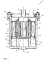
- ein Kraftstoff-Filtersystem mit einem Filtergehäuse und mit darin angeordnetem Filterelement, wobei das Filterelement eine Abscheideeinrichtung, mit einer Auslassöffnung für fluide Abscheideprodukte sowie einen Partikelfilter aufweist, durch den partikuläre Verunreinigungen, die über die Auslassöffnung in das Filterelement verschleppt wurden, aus dem Kraftstoff herausfilterbar sind, in einer Schnittdarstellung;
- Fig. 2
- ein zu dem Filterelement aus
Figur 1 ähnliches Filterelement, bei dem der Partikelfilter im Bereich der Auslassöffnung der Abscheideeinrichtung außen an einer Endplatte des Filterelements angeordnet ist.
- Fig. 1
- a fuel filter system having a filter housing and disposed therein filter element, wherein the filter element has a separator, with an outlet for fluid deposition products and a particulate filter, are filtered out of the fuel by the particulate impurities that were carried over the outlet opening in the filter element in a sectional view;
- Fig. 2
- on to the filter element
FIG. 1 similar filter element, wherein the particulate filter is arranged in the region of the outlet opening of the separator outside of an end plate of the filter element.
In
Das Filtergehäuse 12 weist einen Gehäusebehälter 16 auf, der mittels eines am Gehäusebehälter 16 lösbar angeordneten Gehäusedeckels 18 verschlossen ist. Am Gehäusedeckel 18 ist eine Kraftstoffzuführung 20 für den zu filtrierenden Kraftstoff und ein Auslass 22 in Form einer Kraftstoffabführung für den im Filtersystem 10 gefilterten Kraftstoff befestigt.The
Das Filterelement 14 weist einen im Wesentlichen zylindrischen Querschnitt auf. Zwischen einer oberen Endplatte 24 und einer unteren Endplatte 26 des Filterelements 14 ist ein ringförmig geschlossenes sterngefaltetes Filtermedium 28 angeordnet.The
Das Filtermedium 28 wird im Betrieb des Filtersystems 10 von dem zu filtrierenden Kraftstoff in einer zur Längsachse 30 des Filterelements 14 radialen Strömungsrichtung von außen nach innen durchströmt.During operation of the
In Strömungsrichtung hinter dem Filtermedium 28 ist eine Abscheideeinrichtung 31 zum Abscheiden von im Kraftstoff enthaltenen fluiden Verunreinigungen, hier Wasser, angeordnet.In the flow direction behind the
Die Abscheideeinrichtung 31 umfasst vorliegend ein Coalescer-Element 32 und ein Wasserabscheidesieb 34, die in Strömungsrichtung hintereinanderliegend angeordnet sind. Zwischen dem Coalescer-Element 32 und dem siebförmigen Wasserabscheideelement 34 ist ein Abscheideraum 36 ausgebildet. Der Abscheideraum 36 dient einem der Schwerkraft folgenden Absetzen von aus dem Kraftstoff abgeschiedenen Abscheideprodukten, hier insbesondere Wassermolekülen bzw. Wassertropfen. Der Abscheideraum 36 weist eine Wasserauslassöffnung 38 für die Abscheideprodukte auf, die durch die untere Endplatte 26 des Filterelements 14 begrenzt ist. Die Abscheideprodukte bewegen sich im Betrieb des Filtersystems 10 der Schwerkraft folgend nach unten in Richtung auf und durch die Wasserauslassöffnung 38 in einen bodenseitig angeordneten Wassersammelraum 40 des Filtergehäuses 12.In the present case, the
Der Wassersammelraum 40 ist über die Wasserauslassöffnung 38 mit dem Abscheideraum 36 verbunden.The
Wie aus der
Bei einem Austausch des Filterelements 14 können an dem Filtermedium 28 außenseitig anhaftende Verunreinigungen und auch verunreinigter Kraftstoff in den Wassersammelraum 40 des Filtergehäuses 12 eingebracht werden. Im Wassersammelraum 40 enthaltene Verunreinigungen, insbesondere Partikel, können nach einem Austausch des Filterelements 14 über die Wasserauslassöffnung 38 (retrograd) in den Abscheideraum 36 des Filtersystems 10 eingeschleppt werden, da der Wassersammelraum 40 mit dem Abscheideraum 36 fluidisch in Verbindung steht.When the
Das in
Der Partikelfilter 46 ist vorliegend als ringförmig geschlossener sterngefalteter Balg ausgebildet und kann beispielsweise über endseitig angespritzte Dichtungsteile an den Endplatten 24, 26 des Filterelements 14 bzw. in radialer Richtung an dem Wasserabscheideelement 34 dichtend anliegen. Zur Abstützung des Partikelfilters 46 liegt der Partikelfilter 46 mit seiner radialen Innenseite an einem Mittelrohr 47 an.In the present case, the
Fluidisch betrachtet befindet sich nach dem Partikelfilter 46 ein Reinraum R des Filtersystems 10.Viewed fluidically, a clean room R of the
Der Partikelfilter 46 besteht bevorzugt aus einem hydrophilen Fasermaterial und weist eine im Vergleich zum Filtermedium 28 größere Porengröße auf. Die Porengröße des Partikelfilters 46 kann insbesondere zwischen 50 Mikrometern und 200 Mikrometern betragen.The
Die Partikelfilter 46, 46' umfassen hydrophile Fasern, beispielsweise Zellulosefasern, um ein zuverlässiges Abführen der im Abscheideraum 36, 36' abgeschiedenen Wassermoleküle bzw. Wassertropfen in den Wassersammelraum 40 zu gewährleisten. Die Fasern können insbesondere Mikrofasern sein. Die Fasern können dabei einen unidirektionalen oder im Wesentlichen unidirektionalen Faserverlauf aufweisen, um ein Abführen der Abscheideprodukte aus dem Abscheideraum 36, 36' in den Wassersammelraum 40 zu fördern.The particle filters 46, 46 'comprise hydrophilic fibers, for example cellulose fibers, in order to ensure a reliable discharge of the water molecules or water droplets deposited in the
Es versteht sich, dass das in
Zusammenfassend betrifft die Erfindung ein Filterelement zur Reinigung eines Flüssigmediums. Das Filterelement ist in ein Filtergehäuse eines Filtersystems einsetzbar und weist ein Filtermedium auf. Dem Filtermedium ist zunächst ein Wasserabscheidesieb und danach ein Reinraum fluidisch nachgeordnet. Das am Wasserabscheidesieb abprallende Wasser fließt über eine Wasserauslassöffnung in einen Wassersammelraum des Filtergehäuses. Der Wassersammelraum steht daher fluidisch in Verbindung mit dem Reinraum. Nun können beim Austausch des Filterelements Schmutzpartikel in den Wassersammelraum gelangen. Um die Übertragung dieser Schmutzpartikel aus dem Wassersammelraum in den Reinraum zu vermeiden, ist zwischen dem Wassersammelraum und dem Reinraum ein Partikelfilter angeordnet. Die Erfindung betrifft weiterhin ein Filtersystem mit einem zuvor beschriebenen Filterelement.In summary, the invention relates to a filter element for cleaning a liquid medium. The filter element can be inserted into a filter housing of a filter system and has a filter medium. The filter medium is first followed by a Wasserabscheidesieb and then a clean room fluidly. The rebounding water on the water separator flows through a water outlet in a water collection chamber of the filter housing. The water collection room is therefore fluidly in communication with the clean room. Now, when replacing the filter element dirt particles can get into the water collection chamber. In order to avoid the transfer of these dirt particles from the water collection room into the clean room, a particle filter is arranged between the water collection room and the clean room. The invention further relates to a filter system with a filter element described above.
Claims (10)
ein Partikelfilter (46, 46') im Bereich der Wasserauslassöffnung (38') oder zwischen der Wasserauslassöffnung (38) und dem Auslass (22) des Filterelements (14) angeordnet ist.Filter element (14, 14 ') for a liquid medium, in particular diesel fuel, comprising:
a particle filter (46, 46 ') is arranged in the region of the water outlet opening (38') or between the water outlet opening (38) and the outlet (22) of the filter element (14).
Applications Claiming Priority (1)
| Application Number | Priority Date | Filing Date | Title |
|---|---|---|---|
| DE201310016976 DE102013016976A1 (en) | 2013-10-14 | 2013-10-14 | Filter element and filter system for a liquid medium, in particular diesel fuel |
Publications (2)
| Publication Number | Publication Date |
|---|---|
| EP2865433A2 true EP2865433A2 (en) | 2015-04-29 |
| EP2865433A3 EP2865433A3 (en) | 2015-06-10 |
Family
ID=51703006
Family Applications (1)
| Application Number | Title | Priority Date | Filing Date |
|---|---|---|---|
| EP14188543.4A Withdrawn EP2865433A3 (en) | 2013-10-14 | 2014-10-10 | Filter element and filter system for a liquid medium, particularly diesel fuel |
Country Status (5)
| Country | Link |
|---|---|
| US (2) | US10456718B2 (en) |
| EP (1) | EP2865433A3 (en) |
| KR (1) | KR20150043200A (en) |
| CN (2) | CN108771905A (en) |
| DE (1) | DE102013016976A1 (en) |
Cited By (1)
| Publication number | Priority date | Publication date | Assignee | Title |
|---|---|---|---|---|
| DE102017213698A1 (en) | 2017-08-07 | 2019-02-07 | Mahle International Gmbh | Hydrophilic coalescer for a diesel fuel filter element |
Families Citing this family (13)
| Publication number | Priority date | Publication date | Assignee | Title |
|---|---|---|---|---|
| DE102015013351A1 (en) * | 2015-10-15 | 2017-04-20 | Mann + Hummel Gmbh | Coalescing element and filter element with a coalescing element |
| US10625184B2 (en) * | 2015-11-03 | 2020-04-21 | MANN+HUMMEL Filtration Technology Group Inc. | Coalescing filter element |
| DE112017002974T5 (en) * | 2016-07-19 | 2019-03-07 | Cummins Filtration Ip, Inc. | KOALESZER WITH PERFORATED LAYER |
| CN106215479B (en) * | 2016-09-30 | 2018-08-17 | 福州品行科技发展有限公司 | A kind of filter core of adjustable disengaging water |
| CN106267954B (en) * | 2016-09-30 | 2018-03-16 | 福州品行科技发展有限公司 | A kind of water purification catridge of adjustable water quality |
| CN107497168A (en) * | 2017-08-21 | 2017-12-22 | 赛洛克流体设备成都有限公司 | Filter with efficient filter core |
| DE102017217911A1 (en) * | 2017-10-09 | 2019-04-11 | Mahle International Gmbh | fluid filter |
| IT201800009214A1 (en) * | 2018-10-05 | 2020-04-05 | Ufi Filters Spa | FILTER CARTRIDGE FOR FUEL FILTRATION GROUP |
| DE102018219352A1 (en) * | 2018-11-13 | 2020-05-14 | Friedrich-Alexander-Universität Erlangen-Nürnberg | Fuel filter |
| DE102018133569A1 (en) * | 2018-12-21 | 2020-06-25 | Hengst Se | Filter insert for a fuel filter with three-stage filtration |
| CN110219860A (en) * | 2019-05-31 | 2019-09-10 | 陕西法士特齿轮有限责任公司 | A kind of hydraulic medium filter device for automatic transmission |
| KR102315167B1 (en) * | 2021-06-07 | 2021-10-19 | 정관 | Water purification housing and rainwater purification system using the same |
| DE102022123809A1 (en) | 2022-09-16 | 2024-03-21 | Hengst Se | Filter insert with improved filter performance under operating conditions |
Citations (1)
| Publication number | Priority date | Publication date | Assignee | Title |
|---|---|---|---|---|
| DE102009058812A1 (en) | 2009-12-18 | 2011-06-22 | MAHLE International GmbH, 70376 | filtering device |
Family Cites Families (13)
| Publication number | Priority date | Publication date | Assignee | Title |
|---|---|---|---|---|
| US3187895A (en) * | 1963-01-23 | 1965-06-08 | Pall Corp | Fuel-water separator |
| US3262572A (en) * | 1963-05-27 | 1966-07-26 | Purolator Products Inc | Separator-filter |
| DE10138695A1 (en) * | 2001-08-07 | 2003-02-20 | Mann & Hummel Filter | Arrangement for removing water from engine fuel system, has sensor in collection chamber only indicating presence of water if it exceeds level guaranteeing reliable moistening of membrane |
| EP1606037B1 (en) * | 2003-03-21 | 2011-12-28 | MANN+HUMMEL GmbH | Fuel filtering system |
| DE102006051406A1 (en) | 2006-10-27 | 2008-04-30 | Mann + Hummel Gmbh | Fuel filter for cleaning fuel i.e. diesel, in internal-combustion engine, has water discharge pipe arranged within guiding channel, where water contained in water collecting area is discharged via water discharge pipe |
| FR2909732B1 (en) | 2006-12-12 | 2011-09-23 | Filtrauto | TWO-LEVEL FUEL FILTRATION DEVICE |
| DE102008020233A1 (en) | 2008-04-22 | 2009-10-29 | Hydac Filtertechnik Gmbh | Fuel filter system, in particular for diesel engines |
| US8517185B2 (en) * | 2008-10-08 | 2013-08-27 | Cummins Filtration Ip, Inc. | Two stage fuel water separator and particulate filter utilizing pleated nanofiber filter material |
| US8034240B2 (en) * | 2009-03-02 | 2011-10-11 | Parker-Hannifin Corporation | Coalescing element |
| WO2011107265A1 (en) * | 2010-03-04 | 2011-09-09 | Hydac Filtertechnik Gmbh | Filter device and filter element provided therefor |
| DE102010023650A1 (en) * | 2010-06-14 | 2011-12-15 | Mann + Hummel Gmbh | Filter device, in particular liquid filter |
| DE102011120638A1 (en) * | 2011-12-09 | 2013-06-13 | Mann + Hummel Gmbh | Filter element of a fuel filter and method for producing such |
| DE102011120653A1 (en) * | 2011-12-09 | 2013-06-13 | Mann + Hummel Gmbh | Fuel filter of an internal combustion engine and filter element of a fuel filter |
-
2013
- 2013-10-14 DE DE201310016976 patent/DE102013016976A1/en not_active Ceased
-
2014
- 2014-09-12 KR KR20140121167A patent/KR20150043200A/en not_active Application Discontinuation
- 2014-10-10 EP EP14188543.4A patent/EP2865433A3/en not_active Withdrawn
- 2014-10-14 US US14/513,329 patent/US10456718B2/en not_active Expired - Fee Related
- 2014-10-14 CN CN201810660772.6A patent/CN108771905A/en active Pending
- 2014-10-14 CN CN201410540136.1A patent/CN104548739B/en not_active Expired - Fee Related
-
2019
- 2019-10-25 US US16/664,068 patent/US20200122067A1/en not_active Abandoned
Patent Citations (1)
| Publication number | Priority date | Publication date | Assignee | Title |
|---|---|---|---|---|
| DE102009058812A1 (en) | 2009-12-18 | 2011-06-22 | MAHLE International GmbH, 70376 | filtering device |
Cited By (2)
| Publication number | Priority date | Publication date | Assignee | Title |
|---|---|---|---|---|
| DE102017213698A1 (en) | 2017-08-07 | 2019-02-07 | Mahle International Gmbh | Hydrophilic coalescer for a diesel fuel filter element |
| WO2019029857A1 (en) | 2017-08-07 | 2019-02-14 | Mahle International Gmbh | Diesel fuel filter element with a hydrophilic coalescer, and method for producing same |
Also Published As
| Publication number | Publication date |
|---|---|
| CN104548739A (en) | 2015-04-29 |
| US20200122067A1 (en) | 2020-04-23 |
| CN108771905A (en) | 2018-11-09 |
| DE102013016976A1 (en) | 2015-04-16 |
| US20150101975A1 (en) | 2015-04-16 |
| KR20150043200A (en) | 2015-04-22 |
| US10456718B2 (en) | 2019-10-29 |
| CN104548739B (en) | 2018-07-24 |
| EP2865433A3 (en) | 2015-06-10 |
Similar Documents
| Publication | Publication Date | Title |
|---|---|---|
| EP2865433A2 (en) | Filter element and filter system for a liquid medium, particularly diesel fuel | |
| EP2542324B1 (en) | Filter device | |
| EP3004620B1 (en) | Filter element | |
| DE112013005747B4 (en) | Filter, filter element, filter housing and discharge device of a filter | |
| EP1307274A1 (en) | Fluid filter | |
| DE102013012918C5 (en) | Liquid filter and filter element, in particular for fuel | |
| DE202014011016U1 (en) | Cup-shaped housing and device for separating liquid from air | |
| DE102009025393A1 (en) | 3-stage fuel filter | |
| EP2881156A1 (en) | Filter element having a bypass channel and filter assembly with a filter element | |
| EP2854986A1 (en) | Filter device | |
| DE102015003165A1 (en) | Fuel filter with a fuel filter insert with a front and a main filter element | |
| DE102014002631A1 (en) | Filter element and fluid filter with radial vent hole | |
| DE102017003732A1 (en) | Liquid filter for water separation and / or particle filtration of a fuel and / or an aqueous solution, in particular a urea solution, and / or water | |
| DE102010023650A1 (en) | Filter device, in particular liquid filter | |
| EP3221025B1 (en) | Clean-side water-separating filter element having bayonet connection, and fuel filter having a filter element of this type | |
| WO2015018779A1 (en) | Water separating screen for a filter element in a liquid filter | |
| EP3067102B1 (en) | Water separator and water separation system with integrated water discharge device | |
| DE112014005458B4 (en) | Filter element and filter system with off-line filtering | |
| DE102012019862A1 (en) | Filter device, in particular fuel or oil filter | |
| EP2808071B1 (en) | Filter device, in particular for an automotive car | |
| DE102015003163A1 (en) | Fuel filter element and fuel filter with a front and a main filter element and with a Wasserabscheideeinheit | |
| DE102012219885B3 (en) | Liquid filter for fuels in fuel supply system of motor vehicle, has filter element with recess and hydro-cyclone with liquid inlets and liquid outlets, where hydro-cyclone is arranged partially in recess of filter element | |
| DE102015003100A1 (en) | Separator and separator system for impurities contained in fuel | |
| WO2011039013A1 (en) | Filter device | |
| DE102017001100A1 (en) | Fluid filter with a filter cartridge with a pre and a main filter element |
Legal Events
| Date | Code | Title | Description |
|---|---|---|---|
| PUAI | Public reference made under article 153(3) epc to a published international application that has entered the european phase |
Free format text: ORIGINAL CODE: 0009012 |
|
| 17P | Request for examination filed |
Effective date: 20141010 |
|
| AK | Designated contracting states |
Kind code of ref document: A2 Designated state(s): AL AT BE BG CH CY CZ DE DK EE ES FI FR GB GR HR HU IE IS IT LI LT LU LV MC MK MT NL NO PL PT RO RS SE SI SK SM TR |
|
| AX | Request for extension of the european patent |
Extension state: BA ME |
|
| PUAL | Search report despatched |
Free format text: ORIGINAL CODE: 0009013 |
|
| AK | Designated contracting states |
Kind code of ref document: A3 Designated state(s): AL AT BE BG CH CY CZ DE DK EE ES FI FR GB GR HR HU IE IS IT LI LT LU LV MC MK MT NL NO PL PT RO RS SE SI SK SM TR |
|
| AX | Request for extension of the european patent |
Extension state: BA ME |
|
| RIC1 | Information provided on ipc code assigned before grant |
Ipc: B01D 29/58 20060101ALI20150507BHEP Ipc: B01D 29/21 20060101ALI20150507BHEP Ipc: B01D 36/00 20060101AFI20150507BHEP |
|
| R17P | Request for examination filed (corrected) |
Effective date: 20151210 |
|
| RBV | Designated contracting states (corrected) |
Designated state(s): AL AT BE BG CH CY CZ DE DK EE ES FI FR GB GR HR HU IE IS IT LI LT LU LV MC MK MT NL NO PL PT RO RS SE SI SK SM TR |
|
| 17Q | First examination report despatched |
Effective date: 20170720 |
|
| GRAP | Despatch of communication of intention to grant a patent |
Free format text: ORIGINAL CODE: EPIDOSNIGR1 |
|
| INTG | Intention to grant announced |
Effective date: 20191004 |
|
| STAA | Information on the status of an ep patent application or granted ep patent |
Free format text: STATUS: THE APPLICATION IS DEEMED TO BE WITHDRAWN |
|
| 18D | Application deemed to be withdrawn |
Effective date: 20200215 |