EP2890458B1 - Dual panel photodynamic therapy lamp - Google Patents
Dual panel photodynamic therapy lamp Download PDFInfo
- Publication number
- EP2890458B1 EP2890458B1 EP13756136.1A EP13756136A EP2890458B1 EP 2890458 B1 EP2890458 B1 EP 2890458B1 EP 13756136 A EP13756136 A EP 13756136A EP 2890458 B1 EP2890458 B1 EP 2890458B1
- Authority
- EP
- European Patent Office
- Prior art keywords
- lamp
- leds
- treatment
- modules
- degrees
- Prior art date
- Legal status (The legal status is an assumption and is not a legal conclusion. Google has not performed a legal analysis and makes no representation as to the accuracy of the status listed.)
- Not-in-force
Links
- 238000002428 photodynamic therapy Methods 0.000 title claims description 144
- 230000009977 dual effect Effects 0.000 title description 3
- 238000005286 illumination Methods 0.000 claims description 67
- 238000001816 cooling Methods 0.000 claims description 42
- 230000003287 optical effect Effects 0.000 claims description 10
- 239000000758 substrate Substances 0.000 claims description 6
- 238000011282 treatment Methods 0.000 description 192
- 239000003504 photosensitizing agent Substances 0.000 description 89
- 238000000034 method Methods 0.000 description 76
- 239000002243 precursor Substances 0.000 description 55
- 206010000496 acne Diseases 0.000 description 46
- 229960002749 aminolevulinic acid Drugs 0.000 description 45
- ZGXJTSGNIOSYLO-UHFFFAOYSA-N 88755TAZ87 Chemical class NCC(=O)CCC(O)=O ZGXJTSGNIOSYLO-UHFFFAOYSA-N 0.000 description 44
- 208000002874 Acne Vulgaris Diseases 0.000 description 43
- 150000003839 salts Chemical class 0.000 description 40
- 210000003128 head Anatomy 0.000 description 33
- 210000003491 skin Anatomy 0.000 description 33
- -1 for example Chemical class 0.000 description 27
- 239000000203 mixture Substances 0.000 description 26
- 230000003902 lesion Effects 0.000 description 22
- 208000009621 actinic keratosis Diseases 0.000 description 13
- 210000004027 cell Anatomy 0.000 description 13
- 239000002537 cosmetic Substances 0.000 description 13
- 208000037265 diseases, disorders, signs and symptoms Diseases 0.000 description 13
- 239000006071 cream Substances 0.000 description 12
- 230000002757 inflammatory effect Effects 0.000 description 12
- 201000010099 disease Diseases 0.000 description 10
- 238000011200 topical administration Methods 0.000 description 10
- 238000011534 incubation Methods 0.000 description 9
- 230000001681 protective effect Effects 0.000 description 9
- 208000002193 Pain Diseases 0.000 description 7
- 239000007787 solid Substances 0.000 description 7
- 239000000243 solution Substances 0.000 description 7
- QCQCHGYLTSGIGX-GHXANHINSA-N 4-[[(3ar,5ar,5br,7ar,9s,11ar,11br,13as)-5a,5b,8,8,11a-pentamethyl-3a-[(5-methylpyridine-3-carbonyl)amino]-2-oxo-1-propan-2-yl-4,5,6,7,7a,9,10,11,11b,12,13,13a-dodecahydro-3h-cyclopenta[a]chrysen-9-yl]oxy]-2,2-dimethyl-4-oxobutanoic acid Chemical compound N([C@@]12CC[C@@]3(C)[C@]4(C)CC[C@H]5C(C)(C)[C@@H](OC(=O)CC(C)(C)C(O)=O)CC[C@]5(C)[C@H]4CC[C@@H]3C1=C(C(C2)=O)C(C)C)C(=O)C1=CN=CC(C)=C1 QCQCHGYLTSGIGX-GHXANHINSA-N 0.000 description 6
- 239000003570 air Substances 0.000 description 6
- 230000001419 dependent effect Effects 0.000 description 6
- 210000001061 forehead Anatomy 0.000 description 6
- 239000000902 placebo Substances 0.000 description 6
- 229940068196 placebo Drugs 0.000 description 6
- 230000002829 reductive effect Effects 0.000 description 6
- 230000001225 therapeutic effect Effects 0.000 description 6
- 230000000007 visual effect Effects 0.000 description 6
- 206010015150 Erythema Diseases 0.000 description 5
- 230000001815 facial effect Effects 0.000 description 5
- 230000009467 reduction Effects 0.000 description 5
- MYMOFIZGZYHOMD-UHFFFAOYSA-N Dioxygen Chemical group O=O MYMOFIZGZYHOMD-UHFFFAOYSA-N 0.000 description 4
- VEXZGXHMUGYJMC-UHFFFAOYSA-N Hydrochloric acid Chemical compound Cl VEXZGXHMUGYJMC-UHFFFAOYSA-N 0.000 description 4
- 238000003491 array Methods 0.000 description 4
- 239000003814 drug Substances 0.000 description 4
- 238000009472 formulation Methods 0.000 description 4
- 239000007788 liquid Substances 0.000 description 4
- 238000001126 phototherapy Methods 0.000 description 4
- 238000002203 pretreatment Methods 0.000 description 4
- 206010051246 Photodermatosis Diseases 0.000 description 3
- 206010039509 Scab Diseases 0.000 description 3
- 208000000453 Skin Neoplasms Diseases 0.000 description 3
- 230000008901 benefit Effects 0.000 description 3
- 208000035475 disorder Diseases 0.000 description 3
- 230000002500 effect on skin Effects 0.000 description 3
- 239000000839 emulsion Substances 0.000 description 3
- 231100000321 erythema Toxicity 0.000 description 3
- 210000000887 face Anatomy 0.000 description 3
- 239000006260 foam Substances 0.000 description 3
- 239000000499 gel Substances 0.000 description 3
- 230000033001 locomotion Effects 0.000 description 3
- 238000013178 mathematical model Methods 0.000 description 3
- 150000004702 methyl esters Chemical class 0.000 description 3
- 239000002674 ointment Substances 0.000 description 3
- 230000000699 topical effect Effects 0.000 description 3
- 206010028980 Neoplasm Diseases 0.000 description 2
- 206010033733 Papule Diseases 0.000 description 2
- 208000006994 Precancerous Conditions Diseases 0.000 description 2
- 201000004681 Psoriasis Diseases 0.000 description 2
- 238000000862 absorption spectrum Methods 0.000 description 2
- XECAHXYUAAWDEL-UHFFFAOYSA-N acrylonitrile butadiene styrene Chemical compound C=CC=C.C=CC#N.C=CC1=CC=CC=C1 XECAHXYUAAWDEL-UHFFFAOYSA-N 0.000 description 2
- 229920000122 acrylonitrile butadiene styrene Polymers 0.000 description 2
- 239000004676 acrylonitrile butadiene styrene Substances 0.000 description 2
- 239000000853 adhesive Substances 0.000 description 2
- 230000001070 adhesive effect Effects 0.000 description 2
- 230000002411 adverse Effects 0.000 description 2
- XAGFODPZIPBFFR-UHFFFAOYSA-N aluminium Chemical compound [Al] XAGFODPZIPBFFR-UHFFFAOYSA-N 0.000 description 2
- 229910052782 aluminium Inorganic materials 0.000 description 2
- 230000015572 biosynthetic process Effects 0.000 description 2
- 238000006243 chemical reaction Methods 0.000 description 2
- 239000013626 chemical specie Substances 0.000 description 2
- 230000003247 decreasing effect Effects 0.000 description 2
- 238000009826 distribution Methods 0.000 description 2
- 210000005069 ears Anatomy 0.000 description 2
- 230000000694 effects Effects 0.000 description 2
- 239000011521 glass Substances 0.000 description 2
- 230000004886 head movement Effects 0.000 description 2
- BTXNYTINYBABQR-UHFFFAOYSA-N hypericin Chemical compound C12=C(O)C=C(O)C(C(C=3C(O)=CC(C)=C4C=33)=O)=C2C3=C2C3=C4C(C)=CC(O)=C3C(=O)C3=C(O)C=C(O)C1=C32 BTXNYTINYBABQR-UHFFFAOYSA-N 0.000 description 2
- 229940005608 hypericin Drugs 0.000 description 2
- PHOKTTKFQUYZPI-UHFFFAOYSA-N hypericin Natural products Cc1cc(O)c2c3C(=O)C(=Cc4c(O)c5c(O)cc(O)c6c7C(=O)C(=Cc8c(C)c1c2c(c78)c(c34)c56)O)O PHOKTTKFQUYZPI-UHFFFAOYSA-N 0.000 description 2
- 238000011221 initial treatment Methods 0.000 description 2
- 238000002347 injection Methods 0.000 description 2
- 239000007924 injection Substances 0.000 description 2
- JVTAAEKCZFNVCJ-UHFFFAOYSA-N lactic acid Chemical compound CC(O)C(O)=O JVTAAEKCZFNVCJ-UHFFFAOYSA-N 0.000 description 2
- 230000000670 limiting effect Effects 0.000 description 2
- 239000006210 lotion Substances 0.000 description 2
- 230000003211 malignant effect Effects 0.000 description 2
- 239000000463 material Substances 0.000 description 2
- 238000011369 optimal treatment Methods 0.000 description 2
- 239000006072 paste Substances 0.000 description 2
- 230000035515 penetration Effects 0.000 description 2
- 239000008194 pharmaceutical composition Substances 0.000 description 2
- 230000008845 photoaging Effects 0.000 description 2
- 150000004032 porphyrins Chemical class 0.000 description 2
- 238000003825 pressing Methods 0.000 description 2
- SSKVDVBQSWQEGJ-UHFFFAOYSA-N pseudohypericin Natural products C12=C(O)C=C(O)C(C(C=3C(O)=CC(O)=C4C=33)=O)=C2C3=C2C3=C4C(C)=CC(O)=C3C(=O)C3=C(O)C=C(O)C1=C32 SSKVDVBQSWQEGJ-UHFFFAOYSA-N 0.000 description 2
- YGSDEFSMJLZEOE-UHFFFAOYSA-N salicylic acid Chemical compound OC(=O)C1=CC=CC=C1O YGSDEFSMJLZEOE-UHFFFAOYSA-N 0.000 description 2
- 210000004761 scalp Anatomy 0.000 description 2
- 239000000344 soap Substances 0.000 description 2
- 239000000725 suspension Substances 0.000 description 2
- 238000002560 therapeutic procedure Methods 0.000 description 2
- 210000001519 tissue Anatomy 0.000 description 2
- XLYOFNOQVPJJNP-UHFFFAOYSA-N water Substances O XLYOFNOQVPJJNP-UHFFFAOYSA-N 0.000 description 2
- OYINILBBZAQBEV-UWJYYQICSA-N (17s,18s)-18-(2-carboxyethyl)-20-(carboxymethyl)-12-ethenyl-7-ethyl-3,8,13,17-tetramethyl-17,18,22,23-tetrahydroporphyrin-2-carboxylic acid Chemical compound N1C2=C(C)C(C=C)=C1C=C(N1)C(C)=C(CC)C1=CC(C(C)=C1C(O)=O)=NC1=C(CC(O)=O)C([C@@H](CCC(O)=O)[C@@H]1C)=NC1=C2 OYINILBBZAQBEV-UWJYYQICSA-N 0.000 description 1
- ILBBNQMSDGAAPF-UHFFFAOYSA-N 1-(6-hydroxy-6-methylcyclohexa-2,4-dien-1-yl)propan-1-one Chemical compound CCC(=O)C1C=CC=CC1(C)O ILBBNQMSDGAAPF-UHFFFAOYSA-N 0.000 description 1
- MHIITNFQDPFSES-UHFFFAOYSA-N 25,26,27,28-tetrazahexacyclo[16.6.1.13,6.18,11.113,16.019,24]octacosa-1(25),2,4,6,8(27),9,11,13,15,17,19,21,23-tridecaene Chemical class N1C(C=C2C3=CC=CC=C3C(C=C3NC(=C4)C=C3)=N2)=CC=C1C=C1C=CC4=N1 MHIITNFQDPFSES-UHFFFAOYSA-N 0.000 description 1
- KFKRXESVMDBTNQ-UHFFFAOYSA-N 3-[18-(2-carboxylatoethyl)-8,13-bis(1-hydroxyethyl)-3,7,12,17-tetramethyl-22,23-dihydroporphyrin-21,24-diium-2-yl]propanoate Chemical class N1C2=C(C)C(C(C)O)=C1C=C(N1)C(C)=C(C(O)C)C1=CC(C(C)=C1CCC(O)=O)=NC1=CC(C(CCC(O)=O)=C1C)=NC1=C2 KFKRXESVMDBTNQ-UHFFFAOYSA-N 0.000 description 1
- 206010000501 Acne conglobata Diseases 0.000 description 1
- 241000894006 Bacteria Species 0.000 description 1
- 208000013165 Bowen disease Diseases 0.000 description 1
- 208000019337 Bowen disease of the skin Diseases 0.000 description 1
- VSEIDZLLWQQJGK-CHOZPQDDSA-N CCC1=C(C)C2=N\C\1=C/C1=C(C)C(C(O)=O)=C(N1)\C(CC(=O)N[C@@H](CC(O)=O)C(O)=O)=C1/N=C(/C=C3\N/C(=C\2)C(C=C)=C3C)[C@@H](C)[C@@H]1CCC(O)=O Chemical compound CCC1=C(C)C2=N\C\1=C/C1=C(C)C(C(O)=O)=C(N1)\C(CC(=O)N[C@@H](CC(O)=O)C(O)=O)=C1/N=C(/C=C3\N/C(=C\2)C(C=C)=C3C)[C@@H](C)[C@@H]1CCC(O)=O VSEIDZLLWQQJGK-CHOZPQDDSA-N 0.000 description 1
- 241000186427 Cutibacterium acnes Species 0.000 description 1
- 241001464974 Cutibacterium avidum Species 0.000 description 1
- 241001464975 Cutibacterium granulosum Species 0.000 description 1
- 241001635598 Enicostema Species 0.000 description 1
- DGAQECJNVWCQMB-PUAWFVPOSA-M Ilexoside XXIX Chemical compound C[C@@H]1CC[C@@]2(CC[C@@]3(C(=CC[C@H]4[C@]3(CC[C@@H]5[C@@]4(CC[C@@H](C5(C)C)OS(=O)(=O)[O-])C)C)[C@@H]2[C@]1(C)O)C)C(=O)O[C@H]6[C@@H]([C@H]([C@@H]([C@H](O6)CO)O)O)O.[Na+] DGAQECJNVWCQMB-PUAWFVPOSA-M 0.000 description 1
- 206010027626 Milia Diseases 0.000 description 1
- LYPFDBRUNKHDGX-SOGSVHMOSA-N N1C2=CC=C1\C(=C1\C=CC(=N1)\C(=C1\C=C/C(/N1)=C(/C1=N/C(/CC1)=C2/C1=CC(O)=CC=C1)C1=CC(O)=CC=C1)\C1=CC(O)=CC=C1)C1=CC(O)=CC=C1 Chemical compound N1C2=CC=C1\C(=C1\C=CC(=N1)\C(=C1\C=C/C(/N1)=C(/C1=N/C(/CC1)=C2/C1=CC(O)=CC=C1)C1=CC(O)=CC=C1)\C1=CC(O)=CC=C1)C1=CC(O)=CC=C1 LYPFDBRUNKHDGX-SOGSVHMOSA-N 0.000 description 1
- 206010030113 Oedema Diseases 0.000 description 1
- 241001459566 Papulosa Species 0.000 description 1
- 208000012641 Pigmentation disease Diseases 0.000 description 1
- 241000186429 Propionibacterium Species 0.000 description 1
- 206010037888 Rash pustular Diseases 0.000 description 1
- 206010039792 Seborrhoea Diseases 0.000 description 1
- 206010043189 Telangiectasia Diseases 0.000 description 1
- 206010066901 Treatment failure Diseases 0.000 description 1
- XSQUKJJJFZCRTK-UHFFFAOYSA-N Urea Chemical compound NC(N)=O XSQUKJJJFZCRTK-UHFFFAOYSA-N 0.000 description 1
- KMWBBMXGHHLDKL-UHFFFAOYSA-N [AlH3].[Si] Chemical compound [AlH3].[Si] KMWBBMXGHHLDKL-UHFFFAOYSA-N 0.000 description 1
- 238000010521 absorption reaction Methods 0.000 description 1
- 230000001476 alcoholic effect Effects 0.000 description 1
- 239000012080 ambient air Substances 0.000 description 1
- 230000006907 apoptotic process Effects 0.000 description 1
- 239000007864 aqueous solution Substances 0.000 description 1
- 150000004036 bacteriochlorins Chemical class 0.000 description 1
- 238000004364 calculation method Methods 0.000 description 1
- 201000011510 cancer Diseases 0.000 description 1
- 239000004202 carbamide Substances 0.000 description 1
- 239000003795 chemical substances by application Substances 0.000 description 1
- 150000004035 chlorins Chemical class 0.000 description 1
- 238000013461 design Methods 0.000 description 1
- 230000001066 destructive effect Effects 0.000 description 1
- 239000003599 detergent Substances 0.000 description 1
- 239000003085 diluting agent Substances 0.000 description 1
- 229910001882 dioxygen Inorganic materials 0.000 description 1
- 208000037765 diseases and disorders Diseases 0.000 description 1
- 229940079593 drug Drugs 0.000 description 1
- 239000000975 dye Substances 0.000 description 1
- 230000008030 elimination Effects 0.000 description 1
- 238000003379 elimination reaction Methods 0.000 description 1
- 238000000295 emission spectrum Methods 0.000 description 1
- 150000002148 esters Chemical class 0.000 description 1
- 239000008187 granular material Substances 0.000 description 1
- 230000017525 heat dissipation Effects 0.000 description 1
- 125000004051 hexyl group Chemical group [H]C([H])([H])C([H])([H])C([H])([H])C([H])([H])C([H])([H])C([H])([H])* 0.000 description 1
- 150000001261 hydroxy acids Chemical class 0.000 description 1
- 230000006872 improvement Effects 0.000 description 1
- 208000015181 infectious disease Diseases 0.000 description 1
- 238000001802 infusion Methods 0.000 description 1
- 238000005304 joining Methods 0.000 description 1
- 239000003410 keratolytic agent Substances 0.000 description 1
- 235000014655 lactic acid Nutrition 0.000 description 1
- 239000004310 lactic acid Substances 0.000 description 1
- 229940118199 levulan Drugs 0.000 description 1
- 230000007774 longterm Effects 0.000 description 1
- 230000007246 mechanism Effects 0.000 description 1
- YUUAYBAIHCDHHD-UHFFFAOYSA-N methyl 5-aminolevulinate Chemical compound COC(=O)CCC(=O)CN YUUAYBAIHCDHHD-UHFFFAOYSA-N 0.000 description 1
- 230000004048 modification Effects 0.000 description 1
- 238000012986 modification Methods 0.000 description 1
- 230000017074 necrotic cell death Effects 0.000 description 1
- 231100001079 no serious adverse effect Toxicity 0.000 description 1
- FJKROLUGYXJWQN-UHFFFAOYSA-N papa-hydroxy-benzoic acid Natural products OC(=O)C1=CC=C(O)C=C1 FJKROLUGYXJWQN-UHFFFAOYSA-N 0.000 description 1
- 238000007911 parenteral administration Methods 0.000 description 1
- 230000001575 pathological effect Effects 0.000 description 1
- 239000000546 pharmaceutical excipient Substances 0.000 description 1
- 229940109328 photofrin Drugs 0.000 description 1
- 239000006187 pill Substances 0.000 description 1
- 239000004033 plastic Substances 0.000 description 1
- 229920003023 plastic Polymers 0.000 description 1
- 239000004417 polycarbonate Substances 0.000 description 1
- 229920000515 polycarbonate Polymers 0.000 description 1
- 229920000642 polymer Polymers 0.000 description 1
- 239000000843 powder Substances 0.000 description 1
- 230000008569 process Effects 0.000 description 1
- 208000029561 pustule Diseases 0.000 description 1
- 201000004700 rosacea Diseases 0.000 description 1
- 229960004889 salicylic acid Drugs 0.000 description 1
- 230000037390 scarring Effects 0.000 description 1
- 238000005201 scrubbing Methods 0.000 description 1
- 210000001732 sebaceous gland Anatomy 0.000 description 1
- 208000008742 seborrheic dermatitis Diseases 0.000 description 1
- 238000012163 sequencing technique Methods 0.000 description 1
- 210000004927 skin cell Anatomy 0.000 description 1
- 208000017520 skin disease Diseases 0.000 description 1
- 230000036555 skin type Effects 0.000 description 1
- 239000011734 sodium Substances 0.000 description 1
- 229910052708 sodium Inorganic materials 0.000 description 1
- 206010041823 squamous cell carcinoma Diseases 0.000 description 1
- 239000006188 syrup Substances 0.000 description 1
- 235000020357 syrup Nutrition 0.000 description 1
- 239000003826 tablet Substances 0.000 description 1
- 229950010924 talaporfin Drugs 0.000 description 1
- 208000009056 telangiectasis Diseases 0.000 description 1
- 229960002197 temoporfin Drugs 0.000 description 1
- 238000012546 transfer Methods 0.000 description 1
- ZQFGRJWRSLZCSQ-ZSFNYQMMSA-N verteporfin Chemical compound C=1C([C@@]2([C@H](C(=O)OC)C(=CC=C22)C(=O)OC)C)=NC2=CC(C(=C2C=C)C)=NC2=CC(C(=C2CCC(O)=O)C)=NC2=CC2=NC=1C(C)=C2CCC(=O)OC ZQFGRJWRSLZCSQ-ZSFNYQMMSA-N 0.000 description 1
- 229960003895 verteporfin Drugs 0.000 description 1
- 238000003466 welding Methods 0.000 description 1
- 230000029663 wound healing Effects 0.000 description 1
- 230000037303 wrinkles Effects 0.000 description 1
- 210000000216 zygoma Anatomy 0.000 description 1
Images


Classifications
-
- A—HUMAN NECESSITIES
- A61—MEDICAL OR VETERINARY SCIENCE; HYGIENE
- A61N—ELECTROTHERAPY; MAGNETOTHERAPY; RADIATION THERAPY; ULTRASOUND THERAPY
- A61N5/00—Radiation therapy
- A61N5/06—Radiation therapy using light
- A61N5/0613—Apparatus adapted for a specific treatment
- A61N5/062—Photodynamic therapy, i.e. excitation of an agent
-
- A—HUMAN NECESSITIES
- A61—MEDICAL OR VETERINARY SCIENCE; HYGIENE
- A61N—ELECTROTHERAPY; MAGNETOTHERAPY; RADIATION THERAPY; ULTRASOUND THERAPY
- A61N5/00—Radiation therapy
- A61N5/06—Radiation therapy using light
- A61N5/0613—Apparatus adapted for a specific treatment
- A61N5/0616—Skin treatment other than tanning
-
- A—HUMAN NECESSITIES
- A61—MEDICAL OR VETERINARY SCIENCE; HYGIENE
- A61N—ELECTROTHERAPY; MAGNETOTHERAPY; RADIATION THERAPY; ULTRASOUND THERAPY
- A61N5/00—Radiation therapy
- A61N2005/002—Cooling systems
- A61N2005/007—Cooling systems for cooling the patient
-
- A—HUMAN NECESSITIES
- A61—MEDICAL OR VETERINARY SCIENCE; HYGIENE
- A61N—ELECTROTHERAPY; MAGNETOTHERAPY; RADIATION THERAPY; ULTRASOUND THERAPY
- A61N5/00—Radiation therapy
- A61N5/06—Radiation therapy using light
- A61N2005/0626—Monitoring, verifying, controlling systems and methods
-
- A—HUMAN NECESSITIES
- A61—MEDICAL OR VETERINARY SCIENCE; HYGIENE
- A61N—ELECTROTHERAPY; MAGNETOTHERAPY; RADIATION THERAPY; ULTRASOUND THERAPY
- A61N5/00—Radiation therapy
- A61N5/06—Radiation therapy using light
- A61N2005/0632—Constructional aspects of the apparatus
- A61N2005/0633—Arrangements for lifting or hinging the frame which supports the light sources
-
- A—HUMAN NECESSITIES
- A61—MEDICAL OR VETERINARY SCIENCE; HYGIENE
- A61N—ELECTROTHERAPY; MAGNETOTHERAPY; RADIATION THERAPY; ULTRASOUND THERAPY
- A61N5/00—Radiation therapy
- A61N5/06—Radiation therapy using light
- A61N2005/0635—Radiation therapy using light characterised by the body area to be irradiated
- A61N2005/0642—Irradiating part of the body at a certain distance
-
- A—HUMAN NECESSITIES
- A61—MEDICAL OR VETERINARY SCIENCE; HYGIENE
- A61N—ELECTROTHERAPY; MAGNETOTHERAPY; RADIATION THERAPY; ULTRASOUND THERAPY
- A61N5/00—Radiation therapy
- A61N5/06—Radiation therapy using light
- A61N2005/065—Light sources therefor
- A61N2005/0651—Diodes
- A61N2005/0652—Arrays of diodes
-
- A—HUMAN NECESSITIES
- A61—MEDICAL OR VETERINARY SCIENCE; HYGIENE
- A61N—ELECTROTHERAPY; MAGNETOTHERAPY; RADIATION THERAPY; ULTRASOUND THERAPY
- A61N5/00—Radiation therapy
- A61N5/06—Radiation therapy using light
- A61N2005/0658—Radiation therapy using light characterised by the wavelength of light used
- A61N2005/0662—Visible light
- A61N2005/0663—Coloured light
Definitions
- the present invention relates to a dual panel photodynamic therapy lamp.
- Photodynamic therapy is a developing therapy used for treatment of various cancers and also for non-malignant diseases including infections, wound-healing and various dermatological diseases. Photodynamic therapy is also used for cosmetic treatment of the skin.
- PDT involves the administration of a photosensitizer or a precursor thereof to an area of interest. The photosensitizer or precursor thereof is taken up into the cells, where a precursor of a photosensitizer is converted into a photosensitizer.
- the photosensitizer Upon exposure of the area of interest to light, the photosensitizer is excited, usually from a ground singlet state to an excited singlet state. It then undergoes intersystem crossing to a longer-lived excited triplet state.
- PDT has advantages over alternative therapies for treatment of several pathological conditions; including acne, actinic keratosis and various skin cancers.
- a variation of PDT is PDT which is carried out without a photosensitizer or a precursor thereof, i.e. with light alone (also called phototherapy or light therapy).
- U.S. Patent Application Publication No. 2011/0212146 describes the use of certain precursors of photosensitizers, i.e., derivatives of 5-aminolevulinic acid (5-ALA), such as for example, 5-ALA esters and salts thereof, in a method of cosmetic treatment of photoaged skin.
- photosensitizers i.e., derivatives of 5-aminolevulinic acid (5-ALA), such as for example, 5-ALA esters and salts thereof
- U.S. Patent Application Publication No. 2008/0188558 describes the use of certain precursors of photosensitizers, i.e., derivatives of 5-aminolevulinic acid (5-ALA), such as for example, 5-ALA esters and pharmaceutically acceptable salts thereof, in a method for photodynamic treatment of acne, e.g. acne vulgaris.
- photosensitizers i.e., derivatives of 5-aminolevulinic acid (5-ALA), such as for example, 5-ALA esters and pharmaceutically acceptable salts thereof, in a method for photodynamic treatment of acne, e.g. acne vulgaris.
- U.S. Patent Application Publication No. 2010/0137439 describes PDT, and in particular to the use of 5-aminolevulinic acid (5-ALA) and derivatives of 5-ALA in PDT, in which the side-effects (e.g. pain and/or erythema) of PDT, e.g. of PDT of acne, are prevented or reduced.
- 5-ALA 5-aminolevulinic acid
- derivatives of 5-ALA in PDT, in which the side-effects (e.g. pain and/or erythema) of PDT, e.g. of PDT of acne, are prevented or reduced.
- Acne is one of the most common human skin diseases, characterized by areas of skin with seborrhea (scaly red skin), comedones (blackheads and whiteheads), papules (pinheads), pustules (pimples), nodules (large papules) and possibly scarring.
- Acne affects mostly skin with the densest population of sebaceous follicles; these areas include the face, the upper part of the chest, and the back.
- LEDs light emitting diodes
- an array of LEDs can be formed to cover a large area.
- their high efficiency ensures that less heat dissipation is necessary.
- LEDs have long term stability and so it is easier to design lamps which are suitable for tens of thousands of hours of operation.
- U.S. Patent Application Publication No. 2002/0029071 describes an arrangement of 4 panels of LED arrays comprising one panel for directing light to the scalp and 3 panels which are moveably connected to direct light onto the front of the face, the right side of the face and the left side of the face, respectively.
- Such a 4 panel LED lamp may be used for the treatment of the face and/or scalp, however, the arrangement of 4 panels makes the lamp fairly complex.
- a 4 panel LED lamp will also have a considerable weight, i.e. requiring suitable support arms and trolleys for moving the lamp. Due to its footprint, it will take up space in hospitals or private practice.
- U.S. Patent Application Publication No. 2004/0260365 describes a single panel photodynamic therapy lamp comprising a two-dimensional array of LEDs. These photodynamic therapy lamps provide a limited treatment area. For example, when used for the photodynamic treatment of acne of a patient's face, as described in U.S. Patent Application Publication No. 2008/0188558 , the lamp is not suitable to homogeneously illuminate the face in one illumination session and requires an operator to illuminate each side of the face individually. Likewise, when treating acne of a patient's chest or back, only a part of said chest or back can be treated in one illumination session.
- the photodynamic therapy lamp requires a relatively long treatment time, additional operator functions, and additional materials in order to treat both sides of a patient's face or the entire chest or back.
- the lamp must be precisely positioned independently for each side of the patient's face or each part of the patient's back or chest in order to ensure homogeneous illumination, thereby placing additional burdens on the operator to correctly perform the photodynamic treatment.
- the received light dose per side or part of the patient may need to be measured and evaluated, and subsequently, re-treatment of particular areas that did not receive the required light dose may be necessary, thereby further complicating and extending the treatment.
- a photodynamic therapy lamp that provides uniform illumination of the whole face.
- the lamp comprises two light panels with 512 light emitting diodes that deliver a controlled dose of red light.
- the panels can be adjusted to treat either flat areas such as the chest or back or could be adjusted (angled) to treat the face. Neither the details/angles for the treatment of such flat areas nor the details/angles for the treatment of the face are however disclosed.
- a photodynamic therapy lamp comprises two lamp modules only, each lamp module comprising a two-dimensional array of LEDs and each of the lamp modules are configured to be movable between a first position in which the two lamp modules are oriented substantially parallel with each other in substantially the same plane, and a second position in which the angle between the lamp modules is from 50 degrees to 70 degrees.
- a photodynamic therapy lamp comprises two lamp modules only, each lamp module comprising a two-dimensional array of LEDs and each of the lamp modules are configured to be movable between a first position in which an angle between the lamp modules is from 157 degrees to 180 degrees, and a second position in which the angle between the lamp modules is from 50 degrees to 70 degrees.
- a photodynamic therapy lamp comprises two lamp modules only, each lamp module comprising a two-dimensional array of LEDs and each of the lamp modules are configured to be movable only between a range defined between a first position in which an angle between the lamp modules is from 157 degrees to 180 degrees, and a second position in which the angle between the lamp modules is from 50 degrees to 70 degrees.
- the two lamp modules in the first position are oriented substantially parallel with each other in substantially the same plane, i.e. the angle between the lamp modules is approximately 180 degrees.
- the angle in the first position is preferably from 163 to 172 degrees, more preferably the angle in the first position is from 166.5 to 170.5 degrees, and most preferably the angle in the first position is 168.5 degrees.
- a gap between the lamp modules in the first position exists. Said gap in said first position is preferably approximately 16 mm.
- the angle in the second position is preferably from 55 to 65 degrees, more preferably the angle in the second position is from 58 to 62 degrees, and most preferably the angle in the second position is 60 degrees.
- a gap between the lamp modules in the second position exists. Said gap in said second position is preferably approximately 136 mm.
- the LEDs are collimated LEDs.
- collimated in the context of the invention means that the rays of light from each LED have reduced divergence without being perfectly parallel such that there is some overlap of rays form one LED with neighboring LEDs.
- the collimated LEDs include optical mirrors or lenses, preferably lenses. In a preferred embodiment a single lens is provided for each LED.
- the lamp modules are identical.
- the lamp modules are substantially flat.
- the lamp modules include locking elements configured to lock the lamp modules in the first and second positions.
- the lamp modules include visual markings configured to indicate the first and second positions.
- each lamp module comprises a housing, within the housing there is provided the two-dimensional array of LEDs.
- each lamp module comprises a housing having an optical window which, when the photodynamic therapy lamp is in use, faces the treatment surface of a patient.
- a distance between the lamp modules and a treatment surface of a patient is between about 5 cm to about 8 cm.
- the optical window and thus the surface of each lamp module comprising said optical window is substantially flat.
- each lamp module further comprises a substrate on which the array of LEDs is mounted and a heat sink.
- the substrate is the heat sink.
- each lamp module comprises a housing having an optical window, within the housing there is provided the two-dimensional array of LEDs, a substrate on which the array of LEDs is mounted, a heat sink, a cooling unit configured to cool the array of LEDs and at least one driver module.
- the substrate is the heat sink.
- the cooling unit includes at least one fan, preferably a fan configured to provide forced-air cooling of the array of LEDs.
- each array of LEDs includes an identical number of LEDs.
- Each LED array preferably contains 144 LEDs or more, more preferably 192 LEDs or more, even more preferably from 240 to 320 LEDs and most preferably 256 LEDs.
- each array of LEDs is rectangular.
- the array of LEDs is formed of individual LED array elements that are arranged in a regular pattern, preferably in a honeycomb pattern (i.e. hexagonal array) as described in U.S. Patent Application Publication No. 2004/0260365 .
- each LED emits red light, preferably red light at a nominal wavelength of approximately 632 nm ⁇ 5 nm, and more preferably a nominal wavelength of 636 nm.
- each LED emits blue light, preferably blue light at a nominal wavelength of approximately 417 ⁇ 5 nm.
- each array of LEDs consists of a subset of LEDs that emits red light and another subset of LEDs that emits blue light. Preferably, each subset contains the same number of LEDs.
- An irradiance (fluence rate) of the array of LEDs is from 30 to 150 mW/cm 2 , preferably from 40 to 100 mW/cm 2 and most preferably from 46 mW/cm 2 to 68 mW/cm 2 , e.g. 46 mW/cm 2 and 68 mW/cm 2 .
- a light dose of the array of LEDs is from about 1 to 99 J/cm 2 , more preferably from 5 to 80 J/cm 2 and most preferably from 10 to 70 J/cm 2 .
- the lamp further comprises a base, preferably a moveable base and a support arm movably connecting the two lamp modules with the base.
- the base includes a power source, control electronics, and a patient cooling unit.
- the patient cooling unit includes a fan and an outlet operable by the patient.
- the lamp further comprises a user interface having at least one input device and at least one output device.
- a method of using a photodynamic therapy lamp comprising two lamp modules only, each lamp module comprising a two-dimensional array of LEDs and each of the lamp modules are configured to be movable between a first position first position in which the two lamp modules are oriented substantially parallel with each other in substantially the same plane, and a second position in which the angle between the lamp modules is from 50 degrees to 70 degrees.
- a method of using a photodynamic therapy lamp comprising two lamp modules only, each lamp module comprising a two-dimensional array of LEDs and each of the lamp modules are configured to be movable between a first position in which an angle between the lamp modules is from 157 degrees to 180 degrees, and a second position in which the angle between the lamp modules is from 50 degrees to 70 degrees.
- the method optionally further comprises positioning the lamp modules in the first or second position, preferably locking the lamp modules in said first or second position by means of locking elements.
- the method optionally further comprises prior to positioning the lamp modules in the first or second position, administering a composition comprising a photosensitizer or a precursor of a photosensitizer to a treatment area on a patient and optionally waiting for a period (incubation time).
- the method optionally further comprises aligning the lamp modules to a treatment area on a patient for optimal treatment, preferably by illuminating the treatment area with a subset of the LEDs from the array of LED to determine the correct positioning of the lamp modules in relation to the treatment area.
- the aligning of the lamp modules in the first position includes positioning the lamp modules a predetermined distance from the treatment area. The predetermined distance is preferably from about 5 cm to about 8 cm.
- the method optionally further comprises inputting parameters of a photodynamic treatment via a user interface, and performing the treatment based on the inputted parameters.
- the step of performing the treatment optionally includes emitting light from the array of LEDs of one or both lamp modules.
- the method optionally further comprises cooling the patient by a patient cooling unit including a fan and an outlet operable by the patient.
- a patient cooling unit including a fan and an outlet operable by the patient.
- a method of using a photodynamic therapy lamp comprising two lamp modules only, each lamp module comprising a two-dimensional array of LEDs and each of the lamp modules are configured to be movable between a first position first position in which the two lamp modules are oriented substantially parallel with each other in substantially the same plane, and a second position in which the angle between the lamp modules is from 50 degrees to 70 degrees in which the lamp is configured to be used with a composition comprising a photosensitizer or a precursor of a photosensitizer, preferably with a composition comprising a precursor of a photosensitizer.
- the precursor of a photosensitizer is 5-ALA or a pharmaceutically acceptable salt thereof or a derivative of 5-ALA or a pharmaceutically acceptable salt thereof.
- the precursor of a photosensitizer is a derivative of 5-ALA or a pharmaceutically acceptable salt thereof, more preferably a 5-ALA ester or a pharmaceutically acceptable salt thereof.
- a method of using a photodynamic therapy lamp comprising two lamp modules only, each lamp module comprising a two-dimensional array of LEDs and each of the lamp modules are configured to be movable between a first position in which an angle between the lamp modules is from 157 degrees to 180 degrees, and a second position in which the angle between the lamp modules is from 50 degrees to 70 degrees, in which the lamp is configured to be used with a composition comprising a photosensitizer or a precursor of a photosensitizer, preferably with a composition comprising a precursor of a photosensitizer.
- the precursor of a photosensitizer is 5-ALA or a pharmaceutically acceptable salt thereof or a derivative of 5-ALA or a pharmaceutically acceptable salt thereof.
- the precursor of a photosensitizer is a derivative of 5-ALA or a pharmaceutically acceptable salt thereof, more preferably a 5-ALA ester or a pharmaceutically acceptable salt thereof.
- a method of using a photodynamic therapy lamp comprising two lamp modules only, each lamp module comprising a two-dimensional array of LEDs and each of the lamp modules are configured to be movable between a first position in which the two lamp modules are oriented substantially parallel with each other in substantially the same plane, and a second position in which the angle between the lamp modules is from 50 degrees to 70 degrees, said method comprising (i) applying a composition comprising a photosensitizer or a precursor of a photosensitizer to a treatment area on a patient, (ii) optionally waiting for a period (incubation time), (iii) positioning the lamp modules in one of the first and second positions such that the array of LEDs face the treatment area and (iv) performing the photodynamic treatment.
- a method of using a photodynamic therapy lamp comprising two lamp modules only, each lamp module comprising a two-dimensional array of LEDs and each of the lamp modules are configured to be movable between a first position in which an angle between the lamp modules is from 157 degrees to 180 degrees, and a second position in which the angle between the lamp modules is from 50 degrees to 70 degrees, said method comprising (i) applying a composition comprising a photosensitizer or a precursor of a photosensitizer to a treatment area on a patient, (ii) optionally waiting for a period (incubation time), (iii) positioning the lamp modules in one of the first and second positions such that the array of LEDs face the treatment area and (iv) performing the photodynamic treatment.
- a method of using a photodynamic therapy lamp comprising two lamp modules only, each lamp module comprising a two-dimensional array of LEDs and each of the lamp modules are configured to be movable between a first position in which the two lamp modules are oriented substantially parallel with each other in substantially the same plane, and a second position in which the angle between the lamp modules is from 50 degrees to 70 degrees, said method comprising (i) positioning the lamp modules in one of the first and second positions such that the array of LEDs face the treatment area and (ii) performing the photodynamic treatment.
- a method of using a photodynamic therapy lamp comprising two lamp modules only, each lamp module comprising a two-dimensional array of LEDs and each of the lamp modules are configured to be movable between a first position in which an angle between the lamp modules is from 157 degrees to 180 degrees, and a second position in which the angle between the lamp modules is from 50 degrees to 70 degrees, said method comprising (i) positioning the lamp modules in one of the first and second positions such that the array of LEDs face the treatment area and (ii) performing the photodynamic treatment.
- a photodynamic therapy lamp having two lamp modules only (hereinafter lamp modules or modules), preferably in a housing, in which the modules are connected via a hinge.
- lamp modules or modules In a planar orientation, i.e. a first position, the two LED lamp modules are oriented substantially parallel with each other in substantially the same plane. In said first position, the lamp modules evenly illuminate a relatively flat surface. That is, in the planar orientation, i.e. the first position, the angle between the two lamp modules is approximately 180 degrees. No or only a small gap is present between the two modules in the first position due to the absence of a housing or a housing that is designed such that there is a minimal distance between the innermost row of LEDs of each module in said first position (see Fig.
- the angle between the two lamp modules is from 157 degrees to 180 degrees, more preferably from 163 degrees to 172 degrees, even more preferably from 166.5 degrees to 170.5 degrees, and most preferably 168.5 degrees.
- a gap may be present between the two modules in the first position due to the modules being provided in a housing.
- the two lamp modules may be slightly angled toward each other.
- no angling of the two lamp modules toward each other may be necessary to homogeneously illuminate a treatment area.
- the angle between the two lamp modules in a first position may be approximately 180 degrees.
- each of the lamp modules may be rotated towards the other lamp module such that each module illuminates in a direction at least partially facing the other lamp module. That is, in the angled orientation, i.e. the second position, the angle between the two lamp modules is from 50 degrees to 70 degrees, preferably from 55 degrees to 65 degrees, more preferably from 58 degrees to 62 degrees, and most preferably 60 degrees.
- the lamp according to the present invention may be used to treat relatively flat surfaces of a patient, e.g., a patient's chest or back.
- the lamp according to the present invention may be used to treat contoured surfaces of a human, e.g., a patient's face.
- the photodynamic therapy lamp according to the invention can be used for the treatment of larger, relatively flat surfaces of a patient at a single time as well as for the treatment of contoured surfaces of a patient.
- the selected treatment area e.g. larger relatively flat surfaces and contoured surface of a patient
- photodynamic treatment success is dependent on both drug dose and light dose.
- potential treatment side effects including pain, redness and/or edema can occur.
- potential treatment failures include ineffective/insufficient treatment, and/or potential re-treatment
- the photodynamic therapy lamp according to the invention provides an advantage over the lamps of the prior art, e.g. over the lamps described in U.S. Patent Application Publication No. 2004/0260365 which only provide a limited treatment area.
- the part of the treatment area that is not presently undergoing treatment must be covered by appropriate means to prevent stray, unwanted illumination from impinging on such part. Therefore, the use of the lamps described in U.S. Patent Application Publication No.
- 2004/0260365 in photodynamic therapy requires a relatively long treatment time, additional operator functions, and additional materials in order to the entire treatment area.
- the lamp must be precisely positioned independently for each part of the treatment area in order to ensure homogeneous illumination, thereby placing additional burdens on the operator to correctly perform the photodynamic treatment.
- the received light dose per part of treatment area may need to be determined (e.g. measured and evaluated), and subsequently, re-treatment of particular parts that did not receive the required light dose may be necessary, thereby further complicating and extending the treatment.
- the photodynamic therapy lamp according to the invention may be provided with locking positions and/or locking elements that facilitate correct positioning of the lamp modules in the first and second position and that prevent unwanted movement of the lamp modules during treatment.
- a locking element may hold each lamp module in the first position, and the same or a different locking element may hold each lamp module in the second position.
- the locking positions and/or locking elements may provide positive feedback to an operator in order to ensure precise positioning of the lamp modules for treatment, thereby further reducing potential sources of error.
- the two lamp modules of the photodynamic therapy lamp according to the invention each comprise a two-dimensional array of LEDs, preferably a rectangular array of LEDs.
- Each array of LEDs preferably includes an identical number of LEDs. In general the number of LEDs should be sufficient to ensure complete illumination of the treatment area, e.g. the face. However, minimizing the number of LEDs is important since the cooling requirements and the overall weight and size of the lamp modules can be reduced which also impacts of overall costs and complexity.
- Each array of LEDs comprised in the two lamp modules of the photodynamic therapy lamp according to the invention preferably contains 144 LEDs or more, more preferably 192 LEDs or more, even more preferably from 240 to 320 LEDs and most preferably 256 LEDs.
- the array of LEDs is formed of individual LED array elements that are arranged in a regular pattern, preferably in a honeycomb pattern (i.e. hexagonal array) as described in U.S. Patent Application Publication No. 2004/0260365 .
- a honeycomb pattern i.e. hexagonal array
- said LEDs are preferably arranged in a regular pattern made of 16 individual LED array elements, each of said elements consisting of 16 LEDs.
- the LEDs are preferably collimated LEDs and the lamp modules of the photodynamic therapy lamp of the invention comprise optical mirrors or lenses, preferably lenses, configured to collimate light emitted from the LEDs.
- the lenses are provided in the form of an array of lenses, preferably an array of lenses that matches the array of LEDs such that a single lens is provided for each LED.
- the two lamp modules of the photodynamic therapy lamp according to the invention preferably each comprise a two-dimensional array of LEDs and a two-dimensional array of lenses, preferably a rectangular array of LEDs and a rectangular array of lenses, and the number of LEDs in said array of LEDs corresponds to the number of lenses in said array of lenses.
- each lamp module of the photodynamic therapy lamp according to the invention comprises a two-dimensional array of LEDs which consists of 256 LEDs and a matching two-dimensional array of lenses which consists of 256 lenses.
- said 256 LEDs are arranged in a regular pattern made of 16 individual LED array elements, each of said elements consisting of 16 LEDs and said 256 lenses are arranged in a regular pattern made of 16 individual lens array elements, each of said elements consisting of 16 lenses.
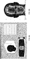
- FIG. 1 illustrates an exemplary embodiment of a photodynamic therapy lamp 10 according to the present invention.
- the lamp 10 includes a lamp head 20, a support arm 30, and a base 40.
- the lamp head 20 comprises two adjacent, substantially flat lamp modules 21 comprising each a two-dimensional array of LEDs and a housing, a hinge 22, a yoke 23 and a user interface.
- the two lamp modules 21 are connected to each other by a hinge 22 which allows the lamp modules 21 to be individually moved relative to each other, i.e. rotated towards and from each other to be positioned for treatment.
- the hinge 22 preferably comprises elements to lock the lamp modules in said first and second position (locking elements) and that prevent unwanted movement of the lamp modules during treatment.
- a locking element may hold each lamp module in the first position, and the same or a different locking element may hold each lamp module in the second position.
- the locking elements may provide positive feedback to an operator in order to ensure precise positioning of the lamp modules for treatment, thereby further reducing potential sources of error.
- the lamp head 20 further comprises a yoke 23 which connects the two lamp modules 21 to the support arm 30.
- a rotating joint is preferably present at the connection of the yoke 23 and each lamp module 21 which permits the two lamp modules 21 to be rotated about a horizontal "x" axis, thus being able to be positioned into a position wherein the array of LEDs face towards a vertically oriented treatment area, e.g. the face, chest or back of a sitting patient or towards a horizontally oriented treatment area, e.g. the face, chest or back of a lying patient.
- a rotating joint is preferably present at the connection of the yoke 23 and the support arm 30 which permits the lamp head 20 to be rotated about a vertical "z" axis.
- a user interface 24 may be provided for controlling the lamp 10.
- the user interface may include an input device, such as a keyboard or keypad, and an output device, such as a display, an LCD display and/or an audio output.
- the user interface may be situated on the lamp head 20 and configured to drive the LEDs.
- the user interface may control power sequencing, and monitor and report faults in the lamp 10.
- the support arm 30 is connected at one end to the base 40, and is connected at the other end to the lamp head 20.
- the support arm allows the lamp head 20 to be moved relative to the base 40.
- the support arm 30 may be a self-balancing arm that is configured to suspend the lamp head 20 in the desired position for treatment, e.g. in a position for the treatment of a patient's face, back or chest and to maintain this position without drift for the duration of the treatment.
- the base 40 may include a power source, and/or may include a connection to an external power source.
- the base 40 may include wheels 41, and associated brakes, so that the photodynamic therapy lamp 10 can be moved and temporarily held stationary.
- the base 40 may include a trolley, e.g., a mobile stand with wheels and associated brakes, that allow the lamp 10 to be moved to a site of treatment and maneuvered for access.
- An integrated vertical pillar 42 of the base 40 may provide an anchor point for the support arm 30 and ensures that the lamp head 20 is held at a height suitable for treatment of a sitting or lying patient, e.g. a patient sitting on a chair or lying on a bed.
- the base 40 may also house the power supply and electronics for the lamp 10, and an optional patient cooling unit 43 having a fan that draws in ambient air and a cooling air outlet, e.g., hose/duct, controllable by the patient/operator.
- the base 40 may be configured as a table mounted support and/or a wall mounted support.
- FIGS 2A, 2B and 2C illustrate a planar orientation of the lamp modules 21 of the exemplary embodiment of a photodynamic therapy lamp 10 according to the present invention.
- the lamp modules 21 are oriented substantially parallel with each other in substantially the same plane, i.e. facing the same direction. No or only a small gap is present between the two modules in the first position if there is no housing or a housing that is designed such that there is a minimal distance between the innermost row of LEDs of each module in said first position. In such a case, the angle between the two lamp modules 21 is approximately 180 degrees.
- the angle between the two lamp modules 21 is from 157 degrees to 180 degrees, more preferably from 163 degrees to 172 degrees, even more preferably from 166.5 degrees to 170.5 degrees, and most preferably 168.5 degrees.
- the inner edges of the two lamp modules 21 may be separated from each other by a gap of approximately 16 mm ⁇ 2 mm.
- a larger surface area may be treated at a single time, thereby facilitating shorter treatment times and fewer required operator functions for treatment.
- Such a larger surface area may be the chest of a patient, as illustrated in Figure 2B which shows the treatment of a lying patient's chest (viewed from the anterior end) or sitting patient's chest (top view).
- such a larger surface area may be the back of a patient, as illustrated in Figure 2C , which shows the treatment of a lying patient's back (viewed from the anterior end) or sitting patient's back (top view).
- Figures 3A and 3B illustrate an angled orientation of the lamp modules 21 of the exemplary embodiment of a photodynamic therapy lamp 10 according to the present invention.
- the lamp modules 21 are rotated relative to each other and at least partially facing toward each other, such that an angle between the two lamp modules 21 is from 50 degrees to 70 degrees, preferably from 55 degrees to 65 degrees, more preferably from 58 degrees to 62 degrees, and most preferably 60 degrees.
- the inner edges of the two lamp modules 21 may be separated from each other by a gap of approximately 136 mm ⁇ 2 mm.
- a contoured surface may be treated, e.g. a patient's face as illustrated in Figure 3B which shows the treatment of a sitting patient's face (top view) or lying patient's face (viewed from the anterior end).
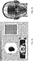
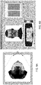
- Figure 4 illustrates one of the two lamp module 21 of the exemplary embodiment of a photodynamic therapy lamp 10 according to the present invention.
- Figure 4A shows a front view of a lamp module 21 with a housing 25 comprising a front enclosure 25a and a rear enclosure 25b (not visible) and a two-dimensional array of LEDs (not visible) which is covered by a matching two-dimensional array of lenses 26.
- the array of lenses is covered by an optically clear window, e.g. a polymer window through which light from the LEDs is emitted for treatment.
- one lamp module 21 includes 256 LEDs 27 which are mounted on a substantially flat support.
- the type of LED is dependent on the wavelength selected for treatment which in turn is dependent on the photosensitizer which is used in the photodynamic treatment.
- the type of LED is selected to have an emission spectrum substantially coincident with the absorption spectrum of the photosensitizer.
- the absorption spectrum of most photosensitizers shows several peaks, i.e. more than one wavelength may be suitable to excite the photosensitizer.
- the wavelength may also be selected according to the penetration depth.
- red light penetrates deeper into the skin than for instance blue light, thus being able to reach and treat deeper layers and structures in the skin, e.g. the sebaceous glands in the case of an acne treatment.
- LEDs are commercially available from various suppliers.
- Preferred LEDs for the photodynamic therapy lamp of the invention are the Luxeon Rebel emitters produced by Lumileds®.
- the individual LEDs are preferably arranged in a regular pattern of 16 x 16 LEDs, preferably in a honeycomb pattern as shown in Figure 4B .
- the array of LEDs is covered by a matching array of lenses 26, e.g., made of polycarbonate, that are configured to collimate the light emitted from the LEDs.
- the individual LEDs array elements may be arranged in a honeycomb pattern with a 12.9 mm pitch or center-to-center distance.
- the LEDs may emit red light, preferably red light having a nominal wavelength of approximately 632 nm ⁇ 5 nm, preferably 636 nm.
- the LEDs may emit blue light, preferably blue light at a nominal wavelength of approximately 417 nm ⁇ 5 nm.
- each array of LEDs consists of a subset of LEDs which emits red light and of another subset of LEDs which emits blue light.
- the number of LEDs in each subset is identical.
- each array of LEDs consists of alternating blue light emitting LEDs and red light emitting LEDs.
- the efficacy of the LEDs for PDT is temperature dependent. That is, with higher temperatures when the lamp 10 is in use and the LEDs generate heat, there is a reduction in luminous output and a shift of wavelength to a higher wavelength. A reduced luminous output requires an extension of the illumination time to achieve a predetermined light dose.
- the illumination time may be variable and extended to achieve the predetermined light dose.
- the illumination time may be set as a fixed parameter.
- the drive current for the LEDs is variable and adapted in operation to meet delivery of the light dose within a fixed illumination time.
- the output of the lamp modules 21 may be preferably varied between a high irradiance (fluence rate) and a low irradiance (fluence rate), e.g. a high fluence rate of approximately 150 mW/cm 2 and a low fluence rate of approximately 30 mW/cm 2 .
- the output of the lamp modules 21 may be preferably varied between a high fluence rate of approximately 68 mW/cm 2 and a low fluence rate of approximately 46 mW/cm 2 .
- the light dose may be varied between 1 and 99 J/cm 2 .
- the light dose may be approximately 10 J/cm 2 when blue light is used for the treatment of acne or actinic keratosis or 37 J/cm 2 when red light is used for the treatment of actinic keratosis or acne or for a cosmetic treatment of photoaged skin.
- the lamp modules 21 may preferably include a cooling system to maintain the temperature of the LEDs for optimal performance.
- the lamp modules 21 may be cooled by forced-air cooling.
- each lamp module 21 may include heat sinks to which the LED arrays are directly mounted, and fans and associated ducts behind each array of LEDs that provide effective forced-air cooling.
- the lamp module 21 may be cooled by convective air cooling using, for example, heat sinks, and/or by liquid cooling using a coil and pump.
- the choice of cooling system may depend on various factors, including, for example, weight, cost, complexity, temperature uniformity, noise, and reliability.
- the LEDs may be mounted on a support made of aluminum, for example, with low thermal resistance, and the support may in turn be thermally bonded to a heat-sink also made of aluminum, for example.
- the support is the heat-sink, i.e. the LEDs are mounted to the heat-sink as illustrated in Figure 4C .
- the support and/or heat sink of each lamp module 21 may be mounted to one or more cooling fans 28 and associated ducts for cooling, and one or more driver modules 29 for control of the lamp module 21 as illustrated in Figure 4D .
- Each lamp module 21 may include two driver boards such that each driver board drives half of the LEDs of each module, e.g., 128 LEDs.
- Each lamp module 21 comprises a housing 25 which comprises a front enclosure 25a and a rear enclosure 25b, e.g. plastic injection molded front and rear enclosures made of ABS (acrylonitrile butadiene styrene).
- Each lamp module 21 may be assembled using various joining methods, including, for example, ultrasonic welding, adhesives, and/or fasteners.
- the photodynamic therapy lamp 10 comprises locking elements to position and maintain the lamp modules 21 in the angled and/or planar orientations, i.e. in the first and second position.
- the locking elements may include positive detents provided at the first and second position of each of the lamp modules 21.
- the lamp modules 21 and/or lamp head 20 may include markings to visually aid an operator in positioning and/or verifying the lamp modules 21 in the first and second position.
- a locking element may hold each lamp module in the first position, and the same or a different locking element may hold each lamp module in the second position.
- the locking elements may provide positive feedback to an operator in order to ensure precise positioning of the lamp modules for treatment, thereby further reducing potential sources of error.
- FIG. 5 illustrates the locking elements of one of the lamp modules 21 of a photodynamic therapy lamp 10 according to the present invention.
- the second lamp module 21 is not shown but preferably comprises identical locking elements.
- the locking elements are part of the hinge 22 and comprise a bearing disc 22a and a guide slot 22b.
- the bearing disc 22a rests at the end of the guide slot 22b in the first and second position, respectively.
- the bearing disc slides in the guide slot until it comes to rest at said second position.
- the center of mass of the lamp head 20 shall not move by more than ⁇ 10 mm from the nominal position when the two lamp modules 21 are moved from the first to the second position (and vice versa) in such a way that they remain symmetrically positioned about the lamp head 20 centerline at all times during the motion.
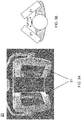
- Figures 6 show the results of 3D mathematical model of the illuminance of a patient's face/head with a lamp according to U.S. Patent Application Publication No. 2004/0260365 .
- the model is based on the geometry and size of a fairly large human head which is covered by a triangular mesh and on the illumination of said head with light emitted from a lamp module comprising an array of collimated LEDs which is described as a regular grid of LEDs over a polygon.
- any array of LEDs can be modeled. The assumption is made that the LEDs are at some distance from the surface of the lamp module, i.e. accounting for lenses configured to collimate light emitted from said LEDs, e.g. for an array of lenses and for an optical window.
- the LEDs are modeled as a point source with some angular intensity function. It is further assumed that the illuminance is uniform over each triangle of the triangular mesh. Based on said model, the illuminance from each LED is calculated at each triangle. The results of the calculation are displayed in color ranging from a red color for the strongest illumination (highest intensity, hot spot) to a dark blue color for the weakest illumination (lowest intensity, cold spot).
- the model was used to calculate the illuminance of a patient's face/head from a lamp according to U.S. Patent Application Publication No. 2004/0260365 , comprising a single lamp module which contains an array of 128 LEDs arranged in a regular honeycomb pattern of 16 x 8 LEDs, as displayed in the top right part of Figure 6A .
- the lamp is sold under the name "Aktilite® 128" by Galderma.
- the lamp module is placed in front of the patient's face as shown in the top left part of Figure 6A at a distance recommended by the supplier.
- Figure 6A shows the illuminance of the patient's face in a 2D picture
- Figure 6B shows the illuminance of the patient's face in a 3D model: only the middle part of the face from the nose/mouth outwards to the middle of the cheeks is illuminated by the lamp.
- the part from the outer corner of the eyes, from the middle of the cheeks outwards, the forehead and the ears are not or only poorly illuminated (i.e. cold spots in blue color).
- illumination is not homogeneous as apparent from the color distribution with a peak illumination of the middle of the forehead, the back of the nose, the chin and the inner corners of the eyes (i.e. hot spots in red color).
- this lamp were used for the photodynamic treatment of a patient's face, e.g. for the treatment of acne, efficacy of said treatment could not be ensured since parts of the face are not illuminated at all and other parts of the face are not homogeneously illuminated, i.e. different light doses are provided to different parts of the face.
- the model was used to calculate the illuminance of a patient's face/head from a lamp according to U.S. Patent Application Publication No. 2004/0260365 , comprising a single lamp module which contains an array of 768 LEDs arranged in a regular honeycomb pattern of 32 x 24 LEDs, as displayed in the top right part of Figure 7A .
- this lamp is an enlarged version of the Aktilite® 128 lamp used in Figures 6 , i.e. comprising a larger array of LEDs which are arranged in the same way as in the Aktilite® 128 lamp.
- the lamp module is placed in front of the patient's face as shown in the top left part of Figure 7A at the same distance as in Figure 6A .
- Figure 7A shows the illuminance of the patient's face in a 2D picture
- Figure 7B shows the illuminance of the patient's face in a 3D model: the whole face including the ears is illuminated by the lamp, however, as for the lamp in Figures 6 , illumination is not homogeneous as apparent from the color distribution with a peak illumination, i.e. hot spots on the forehead, the back of the nose, the chin and the area under the eyes (in red color).
- a peak illumination i.e. hot spots on the forehead, the back of the nose, the chin and the area under the eyes (in red color).
- this lamp were used for the photodynamic treatment of a patient's face, e.g. for the treatment of facial acne, efficacy of said treatment could not be ensured since the face is not homogeneously illuminated, i.e. different light doses are provided to different parts of the face.
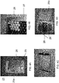
- the model was used to calculate the illuminance of a patient's face/head from a photodynamic therapy lamp 10 according to the invention comprising two lamp modules 21 and each lamp module comprising a two-dimensional array of 256 LEDs and a matching array of lenses.
- the LEDs in each lamp module are arranged in a regular honeycomb pattern of 16 x 16 LEDs as shown for the two lamp modules 21 in the top right of Figure 8B .
- the lamp modules 21 are positioned at a distance of 5-8 cm from the face in an angled orientation, i.e. second position with an angle of 60 degrees ( Figure 8B ), 50 degrees ( Figure 8C ) and 70 degrees ( Figure 8D ) between them.
- Figure 8B /C/D shows the illuminance of the patient's face in a 2D picture while the upper left part of Figure 8B /C/D shows the illuminance of the patient's face in a 3D model.
- the lamp modules 21 positioned with an angle of 60 degrees ( Figure 8B )
- the whole face is optimally homogeneously illuminated by the lamp, i.e. no cold or hot spots occur.
- the lamp modules positioned with an angle of 50 degrees Figure 8C
- the whole face is still fairly homogeneously illuminated, but to a somewhat lesser degree at with the 60 degree angle, which is apparent by the increased illumination in the middle of the forehead.
- homogeneity of the illumination is still acceptable since no cold or hot spots occur.
- the whole face is also fairly homogeneously illuminated, but to a somewhat lesser degree at with the 60 degree angle, which is apparent by the decreased illumination in the middle of the forehead and the back of the nose.
- homogeneity of the illumination is still acceptable since no cold or hot spots occur.
- the model was also used to assess the influence of head movement during treatment on the homogeneity of illumination and it was found that homogeneous illumination is still achieved with a 20 mm offset from the head's nominal position to the right, left, back and forward.
- the photodynamic therapy lamp according to the invention preferably provides a method to the operator to optimally align the patient's face/head and the two lamp modules in the second position, i.e. the angled orientation and to find the optimal distance of the patient's back or chest and the two lamp modules in the first position, i.e. the planar orientation. This will further ensure homogenous illumination of the treatment area and thus safety and efficacy of the treatment.
- two rows of LEDs of each array of LEDs are used to triangulate the position of the line of symmetry of the face/head to the lamp modules.
- the method enables centering, vertical and horizontal positioning in addition to setting the correct lamp module distance from the front of the face/ head.
- two rows of LEDs of each array of LEDs are used to determine the optical vertical positioning, i.e. optimal distance from the lamp modules to the treatment surface.
- a scale or other visual aid may be used to maintain a distance between the lamp modules and the treatment area between about 5 cm to 8 cm.
- such scale or visual aid is provided on the lamp modules.
- the lamp and mathematical model of Figures 8 was used to calculate the illuminance of a patient's face/head as shown in Figures 9 . Only two rows of the two-dimensional array of 256 LEDs were used for the illumination as illustrated in the top right part of Figure 9A .
- the lamp modules 21 and the patient's face/head are positioned as shown in Figure 8A , i.e. the lamp modules 21 are positioned at a distance of 5 to 8 cm from the face in an angled orientation, i.e. second position, with an angle of 60 degrees between them.
- the lower part of Figure 9A shows the illuminance of the patient's face in a 2D picture while the upper left part of Figure 9A shows the illuminance of the patient's face in a 3D model: the line of symmetry of the face/head is homogeneously illuminated without a shadow in the center of the face and the peak illumination is aligned with said line of symmetry, indicating that the lamp is optimally positioned. If the lamp modules are positioned too far away from the patient's face, the offset from the optimal position is visible by reduced intensity (deep blue color) as illustrated in Figure 9B .
- the offset from the optimal position is visible by a shadow in the center of the patient's face which extends from the forehead to the chin, as illustrated in Figure 9C . If the lamp modules are positioned too far to the right (or the left) from the line of symmetry of the face/head this offset from the optimal position is visible by a peak illumination which is off said line of symmetry, i.e. which has moved to the right (or left) as illustrated in Figure 9D .
- the operator positions the lamp modules in the second position, i.e.
- the operator simply has to run the alignment procedure (e.g. by pressing a button on the user interface and/or by selecting the alignment procedure from a menu) and, if there is a shadow visible on the patient's face, re-position the lamp head/lamp until there is no longer a shadow visible and the peak illumination is aligned with the line of symmetry of the patient's face.
- the method of alignment of the lamp modules in the first position i.e. planar orientation is based on the same principle and essentially carried out in the same way.
- the operator moves the lamp modules into the first position and positions the lamp head in a distance of 5-8 cm over a selected treatment area on the patient's back/chest with the arrays of LEDs facing the treatment area (as shown in Figures 2B and 2C ).
- the operator simply has to run the alignment procedure (e.g. by pressing a button on the user interface and/or by selecting the alignment procedure from a menu) and, if there is a shadow visible on the patient's back/chest, re-position the lamp until there is an even illumination without a shadow.
- the lamp may provide a guide light feature, i.e. illumination from all LEDs with reduced intensity in the first or second position.
- a guide light feature i.e. illumination from all LEDs with reduced intensity in the first or second position.
- the operator can check for correct position, e.g. even illumination of the face or back or chest by the lamp. Shadows indicate non- or poorly illuminated areas and the distance between the lamp and the treatment area can be adjusted in such a way that the shadows disappear.
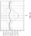
- Figure 10 shows the results of an illuminance modeling of a facet illuminated with a photodynamic therapy lamp according to the invention wherein the lamp modules are positioned in the second position, i.e. from 50 degrees to 70 degrees and outside the second position.
- the model is a simplified version of the 3D mathematical model of the illuminance of a patient's face/head which was used in Figures 6-9 .
- the model of Figure 10 is based on a facet, i.e. a small plain area. An angle of the facet can be introduced to the forward direction as shown in the horizontal axis of Figure 10 .
- the facet By introducing a positive angle of the facet to forward direction, the facet mimics areas of the face which are on the one side of a vertical line forehead-nose-chin and by introducing a negative angle of the facet to forward direction, the facet mimics areas of the face which are on the other side of a vertical line forehead-nose-chin. The larger the angle, the more outwards and away from said vertical line the facet is located.
- a facet at the angle 0 mimics a small, plain area on a vertical line middle of forehead-nose-chin while a facet at the angle +10/-10 roughly mimics a small, plain area on the inner cheekbone, ala of the nose, corner of the mouth and a facet at the angle +90/-90 roughly mimics a small, plain area on ear or the outside of the temple.
- the vertical axis of Figure 10 shows the relative intensity of illumination of the facet being illuminated with the two lamp modules of the photodynamic therapy lamp according to the invention in relation to the angle between the two lamp modules, i.e.
- I 60 degrees is the relative intensity of illumination of the facet being illuminated with the two lamp modules positioned at 60 degrees
- I 55 degrees is the relative intensity of illumination of the facet being illuminated with the two lamp modules positioned at 55 degrees, etc.
- the relative intensity varies from about 0.87 to 1 over a range of angle of facet towards forward direction of -90 to +90 degrees. This means that in the 60 degree position, the areas of a face which are close to the vertical line middle of forehead- nose-chin and the areas of a face which are more outwards and away from said vertical line are about equally illuminated.
- the maximum variation of intensity compared to the optimal 60 degree angle is about 30 % and such a variation of intensity is acceptable.
- the variation of intensity compared to the optimal 60 degree angle is no longer acceptable, i.e. illumination at such angles would no longer be homogeneous.
- angles outside the 50 to 70 degree range would no longer ensure efficacy and safety of said treatment since different light doses (too low/too high) are provided to different parts of the face.
- the photodynamic lamp according to the invention is preferably used for the photodynamic treatment of the skin of a patient, preferably for the photodynamic treatment of contoured treatment areas like face and relatively flat treatment areas like the chest and the back.
- the photodynamic treatment may be a therapeutic treatment, i.e. a treatment to prevent, alleviate or cure a disease or disorder in a patient.
- Preferred examples of such therapeutic treatments are the treatment of dermatological diseases, i.e. diseases and disorders affecting the skin.
- Preferred examples of such dermatological diseases are acne, e.g. acne associated with bacteria such as Propionibacterium (e.g. P. acnes, P. granulosum and/or P.
- the photodynamic treatment may be a cosmetic treatment, i.e. a treatment of ameliorate, alleviate or treat the signs of photoaging and to enhance the appearance of the skin.
- the photodynamic lamp according to the invention may be used in a photodynamic treatment without a photosensitizer (or a precursor of a photosensitizer).
- Such a treatment is also called “phototherapy” or “light therapy” and may be a therapeutic treatment, i.e. a treatment to prevent, alleviate or cure a disease or disorder in a patient or a cosmetic treatment.
- the photodynamic lamp according to the invention may be used in a photodynamic treatment with a photosensitizer (or a precursor of a photosensitizer).
- any known photosensitizers or precursors thereof can be used in a method of PDT wherein the photodynamic therapy lamp according the invention is used.
- Typical such photosensitizers include dyes like hypericin and PVP hypericin, psoralens, porphyrins such as hematoporphyrins, protoporphyrins, uroporphyrins, coproporphyrins, benzoporphyrins or deuteroporphyrins, in particular Photofrin® (profimer sodium), photosan III or verteporfin; chlorins, including bacteriochlorins and isochlorins such as chlorine e6, talaporfin or temoporfin and phthalocyanines such as aluminum- and silicon phthalocyanines.
- precursors of photosensitizers are used in a method of PDT wherein the photodynamic therapy lamp according to the invention is used.
- Typical precursors of photosensitizers include 5-aminolevulinic acid (5-ALA) and certain derivatives thereof, e.g. 5-ALA N-derivatives or 5-ALA esters or salts thereof, preferably derivatives and salts thereof as described in WO 96/28412 , WO 99/53962 , U.S. Patent Application Publication No. 2005/124984 , U.S. Patent Application Publication No. 2008/0064752 and U.S. Patent Application Publication No. 2010/0273725 .
- 5-ALA 5-aminolevulinic acid
- certain derivatives thereof e.g. 5-ALA N-derivatives or 5-ALA esters or salts thereof, preferably derivatives and salts thereof as described in WO 96/28412 , WO 99/53962 , U.S. Patent Application Publication No. 2005/124984 , U
- Photosensitizers or precursors of photosensitizers are formulated with compatible excipients that are known in the art as described for instance in WO 96/28412 , WO 99/53962 , U.S. Patent Application Publication No. 2011/0020441 , U.S. Patent Application Publication No. 2011/0293528 , U.S. Patent Application Publication No. 2012/0134921 , U.S. Patent Application Publication No. 2012/0136055 , U.S. Patent Application Publication No. 2011/0212146 , WO 2011/161220 , and WO 2012/004399 .
- the photosensitizer or precursor of photosensitizer can be formulated as a solution, preferably aqueous solution.
- the photosensitizer or precursor of photosensitizer can be formulated as a solid for oral administration, e.g. a pill, tablet, powder, granulate or alternatively, the photosensitizer or precursor of photosensitizer can be formulated as a semi-solid for oral administration, e.g. a gel, emulsion, foam or ointment.
- the photosensitizer or precursor of photosensitizer can be formulated as a liquid for oral administration, e.g. a solution, suspension or syrup.
- topical administration e.g.
- the photosensitizer or precursor of photosensitizer can be formulated as a liquid, e.g. a solution such as an aqueous and/or alcoholic solution or suspension, as a semi-solid, e.g. a cream, emulsion, lotion, ointment, gel, foam and paste or as a solid, e.g. a transdermal patch.
- a semi-solid e.g. a cream, emulsion, lotion, ointment, gel, foam and paste
- the photosensitizer or precursor of photosensitizers are preferably formulated for topical application to the skin, more preferably as a semi-solid, e.g. a cream, emulsion, lotion, ointment, gel, foam and paste or as a solid, e.g. a transdermal patch.
- the photodynamic lamp according to the invention is used in the treatment of acne, it is preferably used with a precursor of a photosensitizer, more preferably with 5-ALA or a salt thereof or a derivative of 5-ALA or a salt thereof, most preferably with a 5-ALA ester or a salt thereof, e.g. as described in U.S. Patent Application Publication No. 2008/0188558 and U.S. Patent Application Publication No. 2010/0137439 .
- the photodynamic lamp according to the invention is used in the treatment of acne with 5-ALA methyl ester or a salt thereof, preferably with the hydrochloride salt of 5-ALA methyl ester.
- the photodynamic lamp according to the invention is used in the treatment of actinic keratosis it is preferably used with a precursor of a photosensitizer, more preferably with 5-ALA or a salt thereof or a derivative of 5-ALA or a salt thereof, most preferably with a 5-ALA ester or a salt thereof, e.g. as described in U.S. Patent Application Publication No. 2010/0137439 .
- the photodynamic lamp according to the invention is used in the treatment of actinic keratosis with 5-ALA methyl ester or a salt thereof, preferably with the hydrochloride salt of 5-ALA methyl ester.
- the photodynamic lamp according to the invention is used in the cosmetic treatment of photoaged skin, it is preferably used with a precursor of a photosensitizer, more preferably with 5-ALA or a salt thereof or a derivative of 5-ALA or a salt thereof, most preferably with a 5-ALA ester or a salt thereof, e.g. as described in U.S. Patent Application Publication No. 2011/0212146 .
- the photodynamic lamp according to the invention is used in the cosmetic treatment of photoaged skin with 5-ALA hexyl ester or a salt thereof, preferably with the hydrochloride salt or the napsylate salt of 5-ALA hexyl ester.
- concentration of the photosensitizers or precursors of photosensitizers in a pharmaceutical or cosmetic composition for use in a method of PDT with the photodynamic lamp according to the invention procedures depends upon the nature of the photosensitizer or precursor of photosensitizer, the nature of the composition/formulation, the mode of administration, the disease, disorder or condition to be treated and may be varied or adjusted according to choice.
- the concentration of such 5-ALA esters or salts thereof in a pharmaceutical composition for topical administration to the skin is preferably 1 to 20% by weight, more preferably 5 to 16% by weight, even more preferably 6 to 10% by weight and most preferably 7 to 9% by weight.
- the concentration of such 5-ALA esters or salts thereof in a pharmaceutical composition for topical administration to the skin is preferably 1 to 20% by weight, more preferably 5 to 16% by weight.
- the concentration of such 5-ALA esters or salts thereof in a cosmetic composition for topical administration to the skin is preferably 2% or less by weight, more preferably 0.02 to 1.75% by weight, even more preferably 0.05 to 1.5% by weight and most preferably 0.1 to 1% by weight.
- Figure 11 illustrates a method of using the lamp in photodynamic treatment.
- the PDT procedure may optionally start with a pre-treatment of the treatment area, e.g. the skin to be treated.
- a pre-treatment may comprise the step of cleansing the skin with a suitable cleansing agent such as soap/water.
- a suitable cleansing agent such as soap/water.
- pre-treatment may comprise the step of removing dead skin cells on the skin surface, e.g. with keratolytic agents, such as agents comprising urea and/or hydroxy acids such as salicylic acid or lactic acid or by manually scrubbing away such dead cells, e.g. with a brush.
- Pre-treatment may also comprise the step of preparing the surface of a lesion, e.g. an actinic keratosis lesion, with a dermal curette to remove scales and crusts and to roughen the surface of the lesion.
- the photodynamic lamp according to the invention is used with a photosensitizer or precursor of a photosensitizer, a pharmaceutical or cosmetic composition comprising such photosensitizer or precursor of a photosensitizer is administered to the patient at step 11B.
- the photodynamic lamp according to the invention is used without a photosensitizer or precursor of photosensitizer.
- the mode of administration is dependent on the composition and nature of the photosensitizer or precursor of photosensitizer. Typically, administration can be done parenterally (infusion, injection), enterally (e.g. oral or rectal administration) or topically.
- the waiting step 11C is carried out to achieve an effective concentration of photosensitizer in the target cells of the treatment area (incubation time) or to convert the precursor into a photosensitizer and achieve effective concentration of the photosensitizer in the target cells of the treatment area, in case a precursor is used.
- the incubation time is dependent on the nature of the photosensitizer or precursor of photosensitizer, its concentration, its formulation and also its mode of administration. In general, incubation time ranges from 0 minutes to several hours, e.g. 12 hours. For topical administration to skin, the incubation time is 5 min to 4 hours, more preferably 15 min to 3 hours, even more preferably 30 min to 2 hours and most preferably 1 to 1.5 hours.
- the incubation can be carried out under occlusion, e.g. with an adhesive occlusive dressing such as Tegaderm® or Opsite®.
- an adhesive occlusive dressing such as Tegaderm® or Opsite®.
- Such occlusive dressings may enhance the penetration and absorption of a topically-administered formulation.
- the remainder of the composition comprising the photosensitizer or precursor of photosensitizer may be removed, if the composition was topically administered.
- the lamp modules 21 are placed in the planar orientation, i.e. the first position, e.g. by rotating the lamp modules 21 away from each other until the lamp modules 21 are in the correct first position, preferably locked in said first position by means of locking elements. Then, the lamp head 20 is positioned at a distance suitable to homogeneously illuminate said relatively flat treatment surface, e.g. by using the alignment method described hereinbefore.
- the lamp modules 21 are placed in the angled orientation, i.e. second position, e.g. by rotating the lamp modules 21 towards each other until the lamp modules 21 are in the correct second position, preferably locked in said second position by means of locking elements. Then, the lamp head 20 is positioned at a distance suitable to homogeneously illuminate said contoured treatment surface, e.g. by using the alignment method described with reference to Figure 9 .
- the photodynamic treatment parameters e.g. required light dose and/or the illumination time for the LEDs of the lamp modules 21 are input by the operator using the user interface on the lamp 10 at step 11E.
- the photodynamic treatment is performed at the required light dose and illumination time.
- the user interface may display or otherwise indicate the treatment parameters and remaining treatment time.
- the treatment may be (repeatedly) interrupted by the operator, e.g. if the patient experiences pain. The treatment can then be continued at any time within a certain period (e.g. an hour) and the lamp delivers the remaining light dose.
- the user interface may display or otherwise indicate such completion by visual and/or audio output.
- the photodynamic treatment can be paused, restarted, and/or interrupted as necessary in order to provide appropriate treatment to the patient. Further, the patient may use the optional patient cooling unit as desired throughout the treatment.
- the objective of the clinical study was to investigate the efficacy and safety of Visonac® cream comprising 10% by weight 5-ALA methyl ester hydrochloride salt (corresponding to 8% by weight 5-ALA methyl ester) vs. placebo (Visonac® cream formulation without 5-ALA methyl ester hydrochloride) followed by red light illumination carried out with a Nedax® lamp (a photodynamic therapy lamp 10) in severe acne patients.
- the clinical study was a multicenter, randomized, double-blind and placebo controlled study.
- IGA Investigator's Global Assessment
- the two lamp modules 21 were positioned in a planar orientation, i.e. first position for the treatment of the back or chest at an angle of 168.5 degree and in an angled orientation, i.e. second position for the treatment of the face at an angle of 60 degree.
- the lamp modules 21 were positioned at a distance of 5-8 cm from the treatment area.
- the lamp was set to an irradiance (fluence rate) of 68 mW/cm 2 and a light dose of 37 J/cm 2 was provided.
- the patients could use the patient cooling unit of the lamp to provide cooling to the treated areas as desired and possible throughout the treatment.
- the patients wore protective goggles during the treatment
- photodynamic treatment of acne with Visonac® and Nedax® significantly decreased the number of inflammatory lesions and significantly improved IGA success rate compared to placebo.
- the treatment was well tolerated. Comparable efficacy was demonstrated in reducing non-inflammatory lesions.
- Actinic keratosis patients having multiple or few but fairly extensive lesions on the face are treated using a cream comprising 20% by weight 5-ALA methyl ester hydrochloride salt (corresponding to 16% by weight 5-ALA methyl ester), e.g. Metvix® cream (Galderma), followed by red light illumination which is carried out with a Nedax® lamp, a photodynamic therapy lamp 10 according to the invention.
- the surface of the lesions is prepared with a small dermal curette to remove scales and crusts and to roughen the surface of the lesions.
- the cream is administered to the lesions and left to incubate under occlusion for 3 hours.
- the Nedax® lamp comprising two lamp modules 21 only, comprising each a two-dimensional array of 256 LEDs which provide red light at an average wavelength of 632 nm and a matching array of lenses.
- the two lamp modules 21 of the lamp are positioned in an angled orientation, i.e. second position for the treatment of the face at an angle of 60 degree.
- the lamp modules 21 are positioned at a distance of 5-8 cm from the face.
- the lamp is set to an irradiance (fluence rate) of 68 mW/cm 2 and a light dose of 37 J/cm 2 is provided.
- the patients may use the patient cooling unit of the lamp 10 to provide cooling to the face as desired throughout the treatment.
- the patients wear protective goggles during the treatment
- Example 3 Photodynamic treatment of actinic keratosis
- Actinic keratosis patients having multiple or few but fairly extensive lesions on the face are treated using essentially anhydrous 5-ALA hydrochloride which is admixed with a liquid diluents just prior to its use to result in a 20% solution for topical administration to the skin (e.g. Levulan® Kerastick®, Dusa Pharmaceuticals) followed by blue light illumination which is carried out with a photodynamic therapy lamp 10 according to the invention.
- the surface of the lesions is prepared with a small dermal curette to remove scales and crusts and to roughen the surface of the lesions.
- the solution is administered to the lesions. After the initially administered solution has dried, one or more subsequent administrations may be carried out to approximately administer 2 mg/cm 2 of 5-ALA hydrochloride.
- a photodynamic therapy lamp comprising two lamp modules only, comprising each a two-dimensional array of 256 LEDs which provide blue light at an average wavelength of 417 nm and a matching array of lenses.
- the two lamp modules of the lamp are positioned in an angled orientation, i.e. second position for the treatment of the face at an angle of 60 degree.
- the lamp modules are positioned at a distance of 5-8 cm from the face.
- a light dose of 10 J/cm 2 is provided.
- the patients may use the patient cooling unit of the lamp to provide cooling to the face as desired throughout the treatment.
- the patients wear protective goggles during the treatment
- Patients whose faces show typical signs of photoaging such as roughness, sallowness, mottled pigmentation, diffuse facial redness, telangiectasis and/or the formation of fine lines or wrinkles are treated using a cream comprising 0.5 % by weight 5-ALA hexyl ester napsylate or 0.5 % by weight 5-ALA hexyl ester hydrochloride (e.g. Allumera®, Photocure Inc.), followed by red light illumination which is carried out with a Nedax® lamp, a photodynamic therapy lamp 10 according to the invention.
- the face is cleaned with soap/water and gently dried. About 2 g of the cream is administered to all areas of the face except the areas which are covered by goggles during illumination.
- the cream is left on the face for about 1 hour, and the remainder of the cream is removed. Illumination is carried out with the Nedax® lamp comprising two lamp modules 21 only, comprising each a two-dimensional array of 256 LEDs which provide red light at an average wavelength of 632 nm and a matching array of lenses.
- the two lamp modules 21 of the lamp are positioned in an angled orientation, i.e. second position for the treatment of the face at an angle of 60 degree.
- the lamp modules 21 are positioned at a distance of 5-8 cm from the face.
- the lamp is set to an irradiance (fluence rate) of 68 mW/cm 2 and a light dose of 37 J/cm 2 is provided.
- the patients may use the patient cooling unit of the lamp 10 to provide cooling to the face as desired throughout the treatment.
- the patients wear protective goggles during the treatment.
- Nedax® lamp a photodynamic therapy lamp 10
- Illumination is carried out with the Nedax® lamp comprising two lamp modules 21 only, comprising each a two-dimensional array of 256 LEDs which provide red light at an average wavelength of 632 nm and a matching array of lenses.
- the two lamp modules 21 are positioned in a planar orientation, i.e.
- the lamp modules 21 are positioned at a distance of 5-8 cm from the treatment area.
- the lamp is set to an irradiance (fluence rate) of 68 mW/cm 2 and a light dose of 37 J/cm 2 is provided.
- the patients may use the patient cooling unit of the lamp to provide cooling to the treated areas as desired and possible throughout the treatment.
- the patients wear protective goggles during the treatment.
- Such a treatment can be a primary treatment, an alternative to pharmaceuticals or topical, or an adjunct to skin care programs.
- a photodynamic therapy lamp without the use of a photosensitizer or precursor of a photosensitizer. Illumination is carried out with a lamp comprising two lamp modules only, comprising each a two-dimensional array of 256 LEDs which provide blue light at an average wavelength of 417 nm and a matching array of lenses.
- the two lamp modules are positioned in a planar orientation, i.e. first position for the treatment of the back or chest at an angle of 168.5 degree and in an angled orientation, i.e. second position for the treatment of the face at an angle of 60 degree.
- the lamp modules are positioned at a distance of 5-8 cm from the treatment area.
- a light dose of 10 J/cm 2 is provided.
- the patients may use the patient cooling unit of the lamp to provide cooling to the treated areas as desired and possible throughout the treatment.
- the patients wear protective goggles during the treatment.
- the treatment may be carried out about once or twice per week and may go on for about 5 weeks or so.
- Such a treatment can be a primary treatment, an alternative to pharmaceuticals or topical, or an adjunct to skin care programs.
Landscapes
- Health & Medical Sciences (AREA)
- Biomedical Technology (AREA)
- Life Sciences & Earth Sciences (AREA)
- Engineering & Computer Science (AREA)
- Nuclear Medicine, Radiotherapy & Molecular Imaging (AREA)
- Pathology (AREA)
- Biophysics (AREA)
- Radiology & Medical Imaging (AREA)
- Animal Behavior & Ethology (AREA)
- General Health & Medical Sciences (AREA)
- Public Health (AREA)
- Veterinary Medicine (AREA)
- Radiation-Therapy Devices (AREA)
Priority Applications (1)
| Application Number | Priority Date | Filing Date | Title |
|---|---|---|---|
| EP13756136.1A EP2890458B1 (en) | 2012-08-30 | 2013-08-30 | Dual panel photodynamic therapy lamp |
Applications Claiming Priority (3)
| Application Number | Priority Date | Filing Date | Title |
|---|---|---|---|
| EP12182486 | 2012-08-30 | ||
| PCT/EP2013/067982 WO2014033254A1 (en) | 2012-08-30 | 2013-08-30 | Dual panel photodynamic therapy lamp |
| EP13756136.1A EP2890458B1 (en) | 2012-08-30 | 2013-08-30 | Dual panel photodynamic therapy lamp |
Publications (2)
| Publication Number | Publication Date |
|---|---|
| EP2890458A1 EP2890458A1 (en) | 2015-07-08 |
| EP2890458B1 true EP2890458B1 (en) | 2018-05-30 |
Family
ID=46888911
Family Applications (1)
| Application Number | Title | Priority Date | Filing Date |
|---|---|---|---|
| EP13756136.1A Not-in-force EP2890458B1 (en) | 2012-08-30 | 2013-08-30 | Dual panel photodynamic therapy lamp |
Country Status (8)
| Country | Link |
|---|---|
| US (3) | US20140067024A1 (enExample) |
| EP (1) | EP2890458B1 (enExample) |
| JP (1) | JP2015528338A (enExample) |
| BR (1) | BR112015004114A2 (enExample) |
| CA (1) | CA2881614A1 (enExample) |
| EA (1) | EA201590362A1 (enExample) |
| ES (1) | ES2685326T3 (enExample) |
| WO (1) | WO2014033254A1 (enExample) |
Families Citing this family (50)
| Publication number | Priority date | Publication date | Assignee | Title |
|---|---|---|---|---|
| CA2881439C (en) * | 2012-08-10 | 2017-08-29 | Dusa Pharmaceuticals, Inc. | Method for the treatment of acne |
| BR112016014073A2 (pt) | 2013-12-20 | 2017-08-08 | Galderma Res & Dev | Tratamento fotodinâmico de pulso de pele fotodanificada |
| PL410162A1 (pl) | 2014-11-17 | 2016-05-23 | Wojskowa Akademia Techniczna | Oświetlacz LED z wyjściem światłowodowym |
| JP6516219B2 (ja) * | 2015-06-24 | 2019-05-22 | 公立大学法人名古屋市立大学 | 光線力学的治療用光照射装置 |
| EP3328491A4 (en) | 2015-07-28 | 2019-05-01 | PhotonMD, Inc. | SYSTEMS AND METHOD FOR THE LIGHT THERAPEUTIC MODULATION OF STICK OXIDE |
| US12109429B2 (en) | 2015-07-28 | 2024-10-08 | Know Bio, Llc | Phototherapeutic light for treatment of pathogens |
| EP3851161A1 (en) | 2015-10-15 | 2021-07-21 | DUSA Pharmaceuticals, Inc. | Adjustable illuminator for photodynamic therapy and diagnosis |
| US10603508B2 (en) * | 2015-10-15 | 2020-03-31 | Dusa Pharmaceuticals, Inc. | Adjustable illuminators and methods for photodynamic therapy and diagnosis |
| FI20155784A7 (fi) | 2015-11-02 | 2017-05-03 | Cryotech Nordic Oue | Automatisoitu järjestelmä laser-avusteiseen dermatologiseen hoitoon ja ohjausmenetelmä |
| GB201522398D0 (en) * | 2015-12-18 | 2016-02-03 | Photocure As | Device for photodynamic therapy |
| CN106237534B (zh) * | 2016-08-29 | 2018-06-29 | 武汉亚格光电技术股份有限公司 | 智能型鲜红斑痣光动力治疗仪系统 |
| WO2018117787A1 (es) * | 2016-12-19 | 2018-06-28 | Castro Baldenebro Brayan Gamaniel | Sistema de aplicación de luz focalizada para tratamiento de afecciones de la piel causada por acné |
| CA3057840A1 (en) * | 2017-04-14 | 2018-10-18 | Dusa Pharmaceuticals, Inc. | Adjustable illuminators and methods for photodynamic therapy and diagnosis |
| US12233279B2 (en) | 2017-05-30 | 2025-02-25 | Icahn School Of Medicine At Mount Sinai | Device for photo-therapy and use thereof |
| US11273320B2 (en) | 2017-05-30 | 2022-03-15 | Tcellerate Llc | Device for photo-therapy of Grover's disease and use thereof |
| US10155122B1 (en) * | 2017-05-30 | 2018-12-18 | William Woodburn | Device for photo-therapy of grover's disease and use thereof |
| AU2018302103B2 (en) * | 2017-07-17 | 2024-03-07 | Sun Pharmaceutical Industries, Inc. | Photodynamic therapy method for skin disorders |
| CN108310674B (zh) * | 2017-12-21 | 2019-08-13 | 宁波大学 | 一种用于光动力治疗的光源 |
| US10357567B1 (en) | 2018-01-12 | 2019-07-23 | Dusa Pharmaceuticals, Inc. | Methods for photodynamic therapy |
| CN108543226B (zh) * | 2018-04-27 | 2020-01-07 | 王淑娟 | 一种可多角度实施治疗的骨伤恢复烤灯 |
| JP7336756B2 (ja) * | 2018-09-28 | 2023-09-01 | 公立大学法人名古屋市立大学 | 光線治療装置および光線治療装置の光出射方法 |
| US10478635B1 (en) | 2018-10-22 | 2019-11-19 | Joovv, Inc. | Photobiomodulation therapy systems and methods |
| US11458328B2 (en) | 2018-10-22 | 2022-10-04 | Joovv, Inc. | Photobiomodulation therapy device accessories |
| KR102100567B1 (ko) * | 2018-11-14 | 2020-04-13 | 최순철 | 피부관리기 |
| AU2020303417B2 (en) * | 2019-06-25 | 2025-08-28 | Sun Pharmaceutical Industries, Inc. | Methods for reducing pain during photodynamic therapy of actinic keratosis |
| CN110393862A (zh) * | 2019-08-28 | 2019-11-01 | 武汉优瑞科技有限公司 | 一种用于耳朵治疗的光子治疗仪 |
| US11986666B2 (en) | 2020-03-19 | 2024-05-21 | Know Bio, Llc | Illumination devices for inducing biological effects |
| US11147984B2 (en) | 2020-03-19 | 2021-10-19 | Know Bio, Llc | Illumination devices for inducing biological effects |
| US12447354B2 (en) | 2020-03-19 | 2025-10-21 | Know Bio, Llc | Illumination devices for inducing biological effects |
| US12011611B2 (en) | 2020-03-19 | 2024-06-18 | Know Bio, Llc | Illumination devices for inducing biological effects |
| JP7462242B2 (ja) * | 2020-06-19 | 2024-04-05 | パナソニックIpマネジメント株式会社 | 光照射型美容装置及び電子機器 |
| US11235169B1 (en) * | 2020-10-15 | 2022-02-01 | Biofrontera Pharma Gmbh | Illumination device for photodynamic therapy, method for treating a skin disease and method for operating an illumination device |
| US12347337B2 (en) | 2020-12-10 | 2025-07-01 | Know Bio, Llc | Enhanced testing and characterization techniques for phototherapeutic light treatments |
| CN112972904B (zh) * | 2021-02-22 | 2022-06-07 | 四川大学华西医院 | 一种模块化的led灯光动力治疗仪 |
| US12115384B2 (en) | 2021-03-15 | 2024-10-15 | Know Bio, Llc | Devices and methods for illuminating tissue to induce biological effects |
| US11654294B2 (en) | 2021-03-15 | 2023-05-23 | Know Bio, Llc | Intranasal illumination devices |
| ES2928172B2 (es) * | 2021-05-14 | 2023-04-26 | Univ Alcala Henares | Dispositivo luminoso con diodos led orientados |
| US20230043049A1 (en) * | 2021-08-09 | 2023-02-09 | Photonic Healing, LLC DBA Visum Light | Mobile configurable light therapy device |
| USD1073965S1 (en) * | 2021-08-10 | 2025-05-06 | Medmix Co., Ltd. | Medical LED skin enhancement apparatus |
| US20230181923A1 (en) * | 2021-12-09 | 2023-06-15 | Zerigo Health, Inc. | Apparatus and method for treating skin lesions |
| USD1010838S1 (en) * | 2022-01-26 | 2024-01-09 | Kernel Medical Equipment Co., Ltd | Photodynamic therapy device |
| JP2023109524A (ja) * | 2022-01-27 | 2023-08-08 | キヤノンメディカルシステムズ株式会社 | 光照射計画装置、光照射支援装置、医用情報処理システム及び医用情報処理方法 |
| USD1060697S1 (en) * | 2022-08-19 | 2025-02-04 | HOT Brands, LLC | Stand-up red light therapy device |
| KR102511380B1 (ko) | 2022-10-07 | 2023-03-17 | 주식회사 다람 | 남성 생식기 웨어러블 장치 |
| USD1052103S1 (en) * | 2022-10-18 | 2024-11-19 | Biofrontera Pharma Gmbh | Photodynamic therapy lamp head |
| USD1067446S1 (en) * | 2022-10-18 | 2025-03-18 | Biofrontera Pharma Gmbh | Photodynamic therapy lamp |
| EP4605072A1 (en) * | 2022-10-20 | 2025-08-27 | Biofrontera Pharma GmbH | Illumination device for photodynamic therapy, method for treating a skin disease and method for operating an illumination device |
| WO2025160272A1 (en) * | 2024-01-24 | 2025-07-31 | Biofrontera Inc. | Illumination device |
| USD1077259S1 (en) * | 2024-09-02 | 2025-05-27 | Chen Guo | Red light therapy device |
| USD1073918S1 (en) | 2024-12-03 | 2025-05-06 | Erchonia Corporation, Llc | Floor stand for phototherapy device |
Family Cites Families (43)
| Publication number | Priority date | Publication date | Assignee | Title |
|---|---|---|---|---|
| US4740707A (en) * | 1986-10-27 | 1988-04-26 | Allan Thaw | Portable tanning unit |
| US5420768A (en) | 1993-09-13 | 1995-05-30 | Kennedy; John | Portable led photocuring device |
| CZ291132B6 (cs) | 1995-03-10 | 2002-12-11 | Photocure Asa | Estery kyselin 5-aminolevulových a farmaceutický prostředek s jejich obsahem |
| US6712481B2 (en) | 1995-06-27 | 2004-03-30 | Solid State Opto Limited | Light emitting panel assemblies |
| NO972244L (no) | 1997-05-15 | 1998-11-16 | Photocure | Innretning for belysning av et avgrenset omrÕde |
| FR2777782B1 (fr) | 1998-04-22 | 2001-05-18 | Alexandre Marti | Solution pour la preparation d'une substance pharmaceutique pour le diagnostic et/ou le traitement de lesions tissulaires |
| US20060212025A1 (en) | 1998-11-30 | 2006-09-21 | Light Bioscience, Llc | Method and apparatus for acne treatment |
| US6887260B1 (en) | 1998-11-30 | 2005-05-03 | Light Bioscience, Llc | Method and apparatus for acne treatment |
| US6936044B2 (en) | 1998-11-30 | 2005-08-30 | Light Bioscience, Llc | Method and apparatus for the stimulation of hair growth |
| US6663659B2 (en) | 2000-01-13 | 2003-12-16 | Mcdaniel David H. | Method and apparatus for the photomodulation of living cells |
| US20040122492A1 (en) | 1999-07-07 | 2004-06-24 | Yoram Harth | Phototherapeutic treatment of skin conditions |
| US20020128695A1 (en) * | 1999-07-07 | 2002-09-12 | Yoram Harth | Apparatus and method for high energy photodynamic therapy of acne vulgaris and seborrhea |
| US20030216795A1 (en) | 1999-07-07 | 2003-11-20 | Yoram Harth | Apparatus and method for high energy photodynamic therapy of acne vulgaris, seborrhea and other skin disorders |
| GB2360459B (en) | 2000-03-23 | 2002-08-07 | Photo Therapeutics Ltd | Therapeutic light source and method |
| CA2444891A1 (en) | 2001-01-22 | 2002-08-15 | Eric Larsen | Photodynamic stimulation device and methods |
| GB0113899D0 (en) | 2001-06-07 | 2001-08-01 | Photocure Asa | Photodynamic therapy lamp |
| EP1312353A1 (en) | 2001-11-16 | 2003-05-21 | Ecole Polytechnique Federale De Lausanne (Epfl) | Method for hair removal |
| US20060293727A1 (en) | 2002-05-09 | 2006-12-28 | Greg Spooner | System and method for treating exposed tissue with light emitting diodes |
| US20080091250A1 (en) | 2002-09-26 | 2008-04-17 | Lumiport, Llc | Light therapy desk lamp |
| US6872220B2 (en) | 2003-01-16 | 2005-03-29 | Lumitex, Inc. | Infant phototherapy positioning system |
| GB0406917D0 (en) | 2004-03-26 | 2004-04-28 | Photocure Asa | Compounds |
| US7207694B1 (en) | 2004-08-20 | 2007-04-24 | Boyd Industries, Inc. | Light emitting diode operating and examination light system |
| GB0424833D0 (en) | 2004-11-10 | 2004-12-15 | Photocure Asa | Method |
| WO2006060905A1 (en) * | 2004-12-07 | 2006-06-15 | Elumen Lighting Networks Inc. | Assembly of light emitting diodes for lighting applications |
| US20060229689A1 (en) * | 2005-04-08 | 2006-10-12 | Led Technologies, Llc | LED therapy device |
| WO2007087374A2 (en) | 2006-01-24 | 2007-08-02 | Nomir Medical Technologies, Inc. | Optical method and device for modulation of biochemical processes in adipose tissue |
| US7517101B2 (en) * | 2006-03-28 | 2009-04-14 | Tobin Stephen M | Convertible lamp array |
| GB0700580D0 (en) | 2007-01-11 | 2007-02-21 | Photocure Asa | Use |
| JP3133297U (ja) * | 2007-04-25 | 2007-07-05 | 聰章 張 | 方向自在光線療法用具 |
| GB0724279D0 (en) | 2007-12-12 | 2008-01-23 | Photocure Asa | Use |
| JP2011506425A (ja) | 2007-12-14 | 2011-03-03 | フォトデルマ エスアー | 治療的及び美容的方法に有用な新規化合物 |
| CN101965534A (zh) | 2008-02-28 | 2011-02-02 | 皇家飞利浦电子股份有限公司 | 用于分散来自多个光源的光以消除其间的可见边界的装置、具有这样的装置的光疗设备,以及方法 |
| GB0807850D0 (en) * | 2008-04-30 | 2008-06-04 | Photopharmica Ltd | Treatment device |
| US20100106228A1 (en) | 2008-10-27 | 2010-04-29 | Steven Gardner | Device and method of phototherapy for jaundiced infants |
| GB0823472D0 (en) | 2008-12-23 | 2009-01-28 | Photocure Asa | Product |
| GB0900461D0 (en) * | 2009-01-12 | 2009-02-11 | Photocure Asa | Photodynamic therapy device |
| US8734163B1 (en) * | 2009-04-28 | 2014-05-27 | Musco Corporation | Apparatus, method, and system for on-site evaluation of illumination scheme using a mobile lighting evaluation system |
| US20120296260A1 (en) | 2009-06-09 | 2012-11-22 | Freimut Vizethum | Device and method for photodynamic therapy |
| CN102458388B (zh) | 2009-06-11 | 2016-09-28 | 光治疗Asa公司 | 半固体组合物及药物制品 |
| CN102802612A (zh) | 2009-06-11 | 2012-11-28 | 光治疗Asa公司 | 含有5-氨基酮戊酸的固态组合物 |
| JP2013521251A (ja) | 2010-03-01 | 2013-06-10 | フォトキュア エイエスエイ | 美容組成物 |
| EP2585111A1 (en) | 2010-06-23 | 2013-05-01 | Photocure ASA | Hyperosmotic preparations comprising 5 -amino levulinic acid or derivative as photosensitizing agent |
| BR112013000613A2 (pt) | 2010-07-09 | 2016-06-28 | Photocure Asa | composições secas e dispositivos que contêm tais composições secas |
-
2012
- 2012-10-05 US US13/646,274 patent/US20140067024A1/en not_active Abandoned
-
2013
- 2013-08-30 JP JP2015529032A patent/JP2015528338A/ja active Pending
- 2013-08-30 ES ES13756136.1T patent/ES2685326T3/es active Active
- 2013-08-30 BR BR112015004114A patent/BR112015004114A2/pt not_active IP Right Cessation
- 2013-08-30 WO PCT/EP2013/067982 patent/WO2014033254A1/en not_active Ceased
- 2013-08-30 EA EA201590362A patent/EA201590362A1/ru unknown
- 2013-08-30 CA CA2881614A patent/CA2881614A1/en not_active Abandoned
- 2013-08-30 EP EP13756136.1A patent/EP2890458B1/en not_active Not-in-force
-
2015
- 2015-09-24 US US14/863,987 patent/US9399146B2/en not_active Expired - Fee Related
-
2016
- 2016-09-01 US US15/254,850 patent/US20160367832A1/en not_active Abandoned
Non-Patent Citations (1)
| Title |
|---|
| None * |
Also Published As
| Publication number | Publication date |
|---|---|
| US20160008623A1 (en) | 2016-01-14 |
| EP2890458A1 (en) | 2015-07-08 |
| JP2015528338A (ja) | 2015-09-28 |
| BR112015004114A2 (pt) | 2017-07-04 |
| WO2014033254A1 (en) | 2014-03-06 |
| EA201590362A1 (ru) | 2015-11-30 |
| US20160367832A1 (en) | 2016-12-22 |
| US9399146B2 (en) | 2016-07-26 |
| US20140067024A1 (en) | 2014-03-06 |
| ES2685326T3 (es) | 2018-10-08 |
| CA2881614A1 (en) | 2014-03-06 |
Similar Documents
| Publication | Publication Date | Title |
|---|---|---|
| EP2890458B1 (en) | Dual panel photodynamic therapy lamp | |
| US11179574B2 (en) | Method of administering 5-aminolevulinic acid (ALA) to a patient | |
| Sorbellini et al. | Photodynamic and photobiological effects of light-emitting diode (LED) therapy in dermatological disease: an update | |
| Sakamoto et al. | Photodynamic therapy for acne vulgaris: a critical review from basics to clinical practice: part II. Understanding parameters for acne treatment with photodynamic therapy | |
| Keyal et al. | Photodynamic therapy for the treatment of different severity of acne: A systematic review | |
| Moseley et al. | Ambulatory photodynamic therapy: a new concept in delivering photodynamic therapy | |
| KR101244434B1 (ko) | 피부 병변, 피부 신생물 및 피부암, 피부혈관, 통증완화, 다모증완화, 두피모발재생, 피부재생, 피부미백, 피부회춘, 노화방지, 국소지방세포감소, 지방조직감소, 줄기세포 병행치료, 안면 및 전신에 관한 단순치료 혹은 복합광선치료, 공기압 맛사지치료, 공기압 광선역학치료, 고주파, 초음파기기 복합치료, 성형외과, 피부과, 스파병행 시술등에 있어 앨이디, 오앨이디, 레이저 ,레이저 다이오드, 광선, 광선역학 치료방법 및 광선역학 치료기 | |
| Garcia-Zuazaga et al. | Photodynamic therapy in dermatology: current concepts in the treatment of skin cancer | |
| Dong et al. | A new LED device used for photodynamic therapy in treatment of moderate to severe acne vulgaris | |
| US20110224598A1 (en) | Radiant near infrared light emitting diode exposure as skin preparation | |
| Barolet et al. | Radiant near infrared light emitting diode exposure as skin preparation to enhance photodynamic therapy inflammatory type acne treatment outcome | |
| Jang et al. | Photodynamic therapy with ablative carbon dioxide fractional laser in treatment of actinic keratosis | |
| Tao et al. | Low-dose topical 5-aminolevulinic acid photodynamic therapy in the treatment of different severity of acne vulgaris | |
| Falkenberg et al. | Pretreatment with ablative fractional carbon dioxide laser improves treatment efficacy in a synergistic PDT protocol for actinic keratoses on the head | |
| Torezan et al. | Photodynamic therapy in dermatology: basic principles | |
| JP2024527985A (ja) | 設定可能な光線力学的療法システム及び方法 | |
| Kocki et al. | Nurses and pharmacists in interdisciplinary team of health care providers in photodynamic therapy | |
| Savas et al. | Photodynamic therapy | |
| Andreev et al. | Photodynamic therapy as an up-to-date medical technology for the treatment of vulgar acne | |
| Nugrahania et al. | The Utilization of Nanoemulsified Aminolevulinic Acid in Photodynamic Therapy for Actinic Keratosis | |
| Golbari et al. | Daylight Photodynamic Therapy for Actinic Keratosis | |
| Haneke | 6 Photodynamic Treatment | |
| Silva et al. | Design of matrix irradiation system for external tissue phototeraphy | |
| Gold | Lasers and Light Sources for Medical Dermatologic Conditions | |
| TWM263954U (en) | Cosmetology lighting apparatus |
Legal Events
| Date | Code | Title | Description |
|---|---|---|---|
| PUAI | Public reference made under article 153(3) epc to a published international application that has entered the european phase |
Free format text: ORIGINAL CODE: 0009012 |
|
| 17P | Request for examination filed |
Effective date: 20150210 |
|
| AK | Designated contracting states |
Kind code of ref document: A1 Designated state(s): AL AT BE BG CH CY CZ DE DK EE ES FI FR GB GR HR HU IE IS IT LI LT LU LV MC MK MT NL NO PL PT RO RS SE SI SK SM TR |
|
| AX | Request for extension of the european patent |
Extension state: BA ME |
|
| DAX | Request for extension of the european patent (deleted) | ||
| STAA | Information on the status of an ep patent application or granted ep patent |
Free format text: STATUS: EXAMINATION IS IN PROGRESS |
|
| 17Q | First examination report despatched |
Effective date: 20170328 |
|
| GRAP | Despatch of communication of intention to grant a patent |
Free format text: ORIGINAL CODE: EPIDOSNIGR1 |
|
| STAA | Information on the status of an ep patent application or granted ep patent |
Free format text: STATUS: GRANT OF PATENT IS INTENDED |
|
| INTG | Intention to grant announced |
Effective date: 20171213 |
|
| GRAS | Grant fee paid |
Free format text: ORIGINAL CODE: EPIDOSNIGR3 |
|
| GRAA | (expected) grant |
Free format text: ORIGINAL CODE: 0009210 |
|
| STAA | Information on the status of an ep patent application or granted ep patent |
Free format text: STATUS: THE PATENT HAS BEEN GRANTED |
|
| AK | Designated contracting states |
Kind code of ref document: B1 Designated state(s): AL AT BE BG CH CY CZ DE DK EE ES FI FR GB GR HR HU IE IS IT LI LT LU LV MC MK MT NL NO PL PT RO RS SE SI SK SM TR |
|
| REG | Reference to a national code |
Ref country code: GB Ref legal event code: FG4D |
|
| REG | Reference to a national code |
Ref country code: CH Ref legal event code: EP |
|
| REG | Reference to a national code |
Ref country code: AT Ref legal event code: REF Ref document number: 1002994 Country of ref document: AT Kind code of ref document: T Effective date: 20180615 |
|
| REG | Reference to a national code |
Ref country code: IE Ref legal event code: FG4D |
|
| REG | Reference to a national code |
Ref country code: DE Ref legal event code: R096 Ref document number: 602013038189 Country of ref document: DE |
|
| REG | Reference to a national code |
Ref country code: FR Ref legal event code: PLFP Year of fee payment: 6 |
|
| REG | Reference to a national code |
Ref country code: NL Ref legal event code: MP Effective date: 20180530 |
|
| REG | Reference to a national code |
Ref country code: ES Ref legal event code: FG2A Ref document number: 2685326 Country of ref document: ES Kind code of ref document: T3 Effective date: 20181008 |
|
| REG | Reference to a national code |
Ref country code: LT Ref legal event code: MG4D |
|
| PG25 | Lapsed in a contracting state [announced via postgrant information from national office to epo] |
Ref country code: SE Free format text: LAPSE BECAUSE OF FAILURE TO SUBMIT A TRANSLATION OF THE DESCRIPTION OR TO PAY THE FEE WITHIN THE PRESCRIBED TIME-LIMIT Effective date: 20180530 Ref country code: BG Free format text: LAPSE BECAUSE OF FAILURE TO SUBMIT A TRANSLATION OF THE DESCRIPTION OR TO PAY THE FEE WITHIN THE PRESCRIBED TIME-LIMIT Effective date: 20180830 Ref country code: FI Free format text: LAPSE BECAUSE OF FAILURE TO SUBMIT A TRANSLATION OF THE DESCRIPTION OR TO PAY THE FEE WITHIN THE PRESCRIBED TIME-LIMIT Effective date: 20180530 Ref country code: NO Free format text: LAPSE BECAUSE OF FAILURE TO SUBMIT A TRANSLATION OF THE DESCRIPTION OR TO PAY THE FEE WITHIN THE PRESCRIBED TIME-LIMIT Effective date: 20180830 Ref country code: CY Free format text: LAPSE BECAUSE OF FAILURE TO SUBMIT A TRANSLATION OF THE DESCRIPTION OR TO PAY THE FEE WITHIN THE PRESCRIBED TIME-LIMIT Effective date: 20180530 Ref country code: LT Free format text: LAPSE BECAUSE OF FAILURE TO SUBMIT A TRANSLATION OF THE DESCRIPTION OR TO PAY THE FEE WITHIN THE PRESCRIBED TIME-LIMIT Effective date: 20180530 |
|
| PG25 | Lapsed in a contracting state [announced via postgrant information from national office to epo] |
Ref country code: GR Free format text: LAPSE BECAUSE OF FAILURE TO SUBMIT A TRANSLATION OF THE DESCRIPTION OR TO PAY THE FEE WITHIN THE PRESCRIBED TIME-LIMIT Effective date: 20180831 Ref country code: HR Free format text: LAPSE BECAUSE OF FAILURE TO SUBMIT A TRANSLATION OF THE DESCRIPTION OR TO PAY THE FEE WITHIN THE PRESCRIBED TIME-LIMIT Effective date: 20180530 Ref country code: LV Free format text: LAPSE BECAUSE OF FAILURE TO SUBMIT A TRANSLATION OF THE DESCRIPTION OR TO PAY THE FEE WITHIN THE PRESCRIBED TIME-LIMIT Effective date: 20180530 Ref country code: RS Free format text: LAPSE BECAUSE OF FAILURE TO SUBMIT A TRANSLATION OF THE DESCRIPTION OR TO PAY THE FEE WITHIN THE PRESCRIBED TIME-LIMIT Effective date: 20180530 |
|
| REG | Reference to a national code |
Ref country code: AT Ref legal event code: MK05 Ref document number: 1002994 Country of ref document: AT Kind code of ref document: T Effective date: 20180530 |
|
| PG25 | Lapsed in a contracting state [announced via postgrant information from national office to epo] |
Ref country code: NL Free format text: LAPSE BECAUSE OF FAILURE TO SUBMIT A TRANSLATION OF THE DESCRIPTION OR TO PAY THE FEE WITHIN THE PRESCRIBED TIME-LIMIT Effective date: 20180530 |
|
| PG25 | Lapsed in a contracting state [announced via postgrant information from national office to epo] |
Ref country code: RO Free format text: LAPSE BECAUSE OF FAILURE TO SUBMIT A TRANSLATION OF THE DESCRIPTION OR TO PAY THE FEE WITHIN THE PRESCRIBED TIME-LIMIT Effective date: 20180530 Ref country code: CZ Free format text: LAPSE BECAUSE OF FAILURE TO SUBMIT A TRANSLATION OF THE DESCRIPTION OR TO PAY THE FEE WITHIN THE PRESCRIBED TIME-LIMIT Effective date: 20180530 Ref country code: EE Free format text: LAPSE BECAUSE OF FAILURE TO SUBMIT A TRANSLATION OF THE DESCRIPTION OR TO PAY THE FEE WITHIN THE PRESCRIBED TIME-LIMIT Effective date: 20180530 Ref country code: DK Free format text: LAPSE BECAUSE OF FAILURE TO SUBMIT A TRANSLATION OF THE DESCRIPTION OR TO PAY THE FEE WITHIN THE PRESCRIBED TIME-LIMIT Effective date: 20180530 Ref country code: AT Free format text: LAPSE BECAUSE OF FAILURE TO SUBMIT A TRANSLATION OF THE DESCRIPTION OR TO PAY THE FEE WITHIN THE PRESCRIBED TIME-LIMIT Effective date: 20180530 Ref country code: PL Free format text: LAPSE BECAUSE OF FAILURE TO SUBMIT A TRANSLATION OF THE DESCRIPTION OR TO PAY THE FEE WITHIN THE PRESCRIBED TIME-LIMIT Effective date: 20180530 Ref country code: SK Free format text: LAPSE BECAUSE OF FAILURE TO SUBMIT A TRANSLATION OF THE DESCRIPTION OR TO PAY THE FEE WITHIN THE PRESCRIBED TIME-LIMIT Effective date: 20180530 |
|
| PG25 | Lapsed in a contracting state [announced via postgrant information from national office to epo] |
Ref country code: SM Free format text: LAPSE BECAUSE OF FAILURE TO SUBMIT A TRANSLATION OF THE DESCRIPTION OR TO PAY THE FEE WITHIN THE PRESCRIBED TIME-LIMIT Effective date: 20180530 |
|
| REG | Reference to a national code |
Ref country code: DE Ref legal event code: R097 Ref document number: 602013038189 Country of ref document: DE |
|
| PG25 | Lapsed in a contracting state [announced via postgrant information from national office to epo] |
Ref country code: MC Free format text: LAPSE BECAUSE OF FAILURE TO SUBMIT A TRANSLATION OF THE DESCRIPTION OR TO PAY THE FEE WITHIN THE PRESCRIBED TIME-LIMIT Effective date: 20180530 |
|
| REG | Reference to a national code |
Ref country code: CH Ref legal event code: PL |
|
| PLBE | No opposition filed within time limit |
Free format text: ORIGINAL CODE: 0009261 |
|
| STAA | Information on the status of an ep patent application or granted ep patent |
Free format text: STATUS: NO OPPOSITION FILED WITHIN TIME LIMIT |
|
| PG25 | Lapsed in a contracting state [announced via postgrant information from national office to epo] |
Ref country code: LI Free format text: LAPSE BECAUSE OF NON-PAYMENT OF DUE FEES Effective date: 20180831 Ref country code: LU Free format text: LAPSE BECAUSE OF NON-PAYMENT OF DUE FEES Effective date: 20180830 Ref country code: CH Free format text: LAPSE BECAUSE OF NON-PAYMENT OF DUE FEES Effective date: 20180831 |
|
| 26N | No opposition filed |
Effective date: 20190301 |
|
| REG | Reference to a national code |
Ref country code: BE Ref legal event code: MM Effective date: 20180831 |
|
| PG25 | Lapsed in a contracting state [announced via postgrant information from national office to epo] |
Ref country code: SI Free format text: LAPSE BECAUSE OF FAILURE TO SUBMIT A TRANSLATION OF THE DESCRIPTION OR TO PAY THE FEE WITHIN THE PRESCRIBED TIME-LIMIT Effective date: 20180530 |
|
| PG25 | Lapsed in a contracting state [announced via postgrant information from national office to epo] |
Ref country code: BE Free format text: LAPSE BECAUSE OF NON-PAYMENT OF DUE FEES Effective date: 20180831 |
|
| PG25 | Lapsed in a contracting state [announced via postgrant information from national office to epo] |
Ref country code: AL Free format text: LAPSE BECAUSE OF FAILURE TO SUBMIT A TRANSLATION OF THE DESCRIPTION OR TO PAY THE FEE WITHIN THE PRESCRIBED TIME-LIMIT Effective date: 20180530 |
|
| PG25 | Lapsed in a contracting state [announced via postgrant information from national office to epo] |
Ref country code: MT Free format text: LAPSE BECAUSE OF NON-PAYMENT OF DUE FEES Effective date: 20180830 |
|
| PG25 | Lapsed in a contracting state [announced via postgrant information from national office to epo] |
Ref country code: TR Free format text: LAPSE BECAUSE OF FAILURE TO SUBMIT A TRANSLATION OF THE DESCRIPTION OR TO PAY THE FEE WITHIN THE PRESCRIBED TIME-LIMIT Effective date: 20180530 |
|
| PG25 | Lapsed in a contracting state [announced via postgrant information from national office to epo] |
Ref country code: PT Free format text: LAPSE BECAUSE OF FAILURE TO SUBMIT A TRANSLATION OF THE DESCRIPTION OR TO PAY THE FEE WITHIN THE PRESCRIBED TIME-LIMIT Effective date: 20180530 |
|
| PG25 | Lapsed in a contracting state [announced via postgrant information from national office to epo] |
Ref country code: IE Free format text: LAPSE BECAUSE OF NON-PAYMENT OF DUE FEES Effective date: 20180830 Ref country code: HU Free format text: LAPSE BECAUSE OF FAILURE TO SUBMIT A TRANSLATION OF THE DESCRIPTION OR TO PAY THE FEE WITHIN THE PRESCRIBED TIME-LIMIT; INVALID AB INITIO Effective date: 20130830 Ref country code: MK Free format text: LAPSE BECAUSE OF NON-PAYMENT OF DUE FEES Effective date: 20180530 |
|
| PG25 | Lapsed in a contracting state [announced via postgrant information from national office to epo] |
Ref country code: IS Free format text: LAPSE BECAUSE OF FAILURE TO SUBMIT A TRANSLATION OF THE DESCRIPTION OR TO PAY THE FEE WITHIN THE PRESCRIBED TIME-LIMIT Effective date: 20180930 |
|
| PGFP | Annual fee paid to national office [announced via postgrant information from national office to epo] |
Ref country code: FR Payment date: 20200825 Year of fee payment: 8 Ref country code: DE Payment date: 20200827 Year of fee payment: 8 Ref country code: ES Payment date: 20200901 Year of fee payment: 8 Ref country code: GB Payment date: 20200827 Year of fee payment: 8 |
|
| PGFP | Annual fee paid to national office [announced via postgrant information from national office to epo] |
Ref country code: IT Payment date: 20200821 Year of fee payment: 8 |
|
| REG | Reference to a national code |
Ref country code: DE Ref legal event code: R119 Ref document number: 602013038189 Country of ref document: DE |
|
| GBPC | Gb: european patent ceased through non-payment of renewal fee |
Effective date: 20210830 |
|
| PG25 | Lapsed in a contracting state [announced via postgrant information from national office to epo] |
Ref country code: IT Free format text: LAPSE BECAUSE OF NON-PAYMENT OF DUE FEES Effective date: 20210830 Ref country code: GB Free format text: LAPSE BECAUSE OF NON-PAYMENT OF DUE FEES Effective date: 20210830 Ref country code: FR Free format text: LAPSE BECAUSE OF NON-PAYMENT OF DUE FEES Effective date: 20210831 Ref country code: DE Free format text: LAPSE BECAUSE OF NON-PAYMENT OF DUE FEES Effective date: 20220301 |
|
| REG | Reference to a national code |
Ref country code: ES Ref legal event code: FD2A Effective date: 20221104 |
|
| PG25 | Lapsed in a contracting state [announced via postgrant information from national office to epo] |
Ref country code: ES Free format text: LAPSE BECAUSE OF NON-PAYMENT OF DUE FEES Effective date: 20210831 |
|
| P01 | Opt-out of the competence of the unified patent court (upc) registered |
Effective date: 20230524 |