EP2889984A1 - Dispositif et procédé de protection de bloc de batteries - Google Patents
Dispositif et procédé de protection de bloc de batteries Download PDFInfo
- Publication number
- EP2889984A1 EP2889984A1 EP14820400.1A EP14820400A EP2889984A1 EP 2889984 A1 EP2889984 A1 EP 2889984A1 EP 14820400 A EP14820400 A EP 14820400A EP 2889984 A1 EP2889984 A1 EP 2889984A1
- Authority
- EP
- European Patent Office
- Prior art keywords
- battery
- state
- overdischarging
- overcharging
- switch
- Prior art date
- Legal status (The legal status is an assumption and is not a legal conclusion. Google has not performed a legal analysis and makes no representation as to the accuracy of the status listed.)
- Ceased
Links
Images


Classifications
-
- H—ELECTRICITY
- H02—GENERATION; CONVERSION OR DISTRIBUTION OF ELECTRIC POWER
- H02J—ELECTRIC POWER NETWORKS; CIRCUIT ARRANGEMENTS OR SYSTEMS FOR SUPPLYING OR DISTRIBUTING ELECTRIC POWER; SYSTEMS FOR STORING ELECTRIC ENERGY
- H02J7/00—Circuit arrangements for charging or discharging batteries or for supplying loads from batteries
- H02J7/60—Circuit arrangements for charging or discharging batteries or for supplying loads from batteries including safety or protection arrangements
- H02J7/663—Circuit arrangements for charging or discharging batteries or for supplying loads from batteries including safety or protection arrangements using battery or load disconnect circuits
-
- H—ELECTRICITY
- H02—GENERATION; CONVERSION OR DISTRIBUTION OF ELECTRIC POWER
- H02J—ELECTRIC POWER NETWORKS; CIRCUIT ARRANGEMENTS OR SYSTEMS FOR SUPPLYING OR DISTRIBUTING ELECTRIC POWER; SYSTEMS FOR STORING ELECTRIC ENERGY
- H02J7/00—Circuit arrangements for charging or discharging batteries or for supplying loads from batteries
- H02J7/02—Circuit arrangements for charging or discharging batteries or for supplying loads from batteries for charging batteries from AC mains by converters
- H02J7/04—Regulation of charging current or voltage
-
- H—ELECTRICITY
- H02—GENERATION; CONVERSION OR DISTRIBUTION OF ELECTRIC POWER
- H02J—ELECTRIC POWER NETWORKS; CIRCUIT ARRANGEMENTS OR SYSTEMS FOR SUPPLYING OR DISTRIBUTING ELECTRIC POWER; SYSTEMS FOR STORING ELECTRIC ENERGY
- H02J7/00—Circuit arrangements for charging or discharging batteries or for supplying loads from batteries
- H02J7/50—Circuit arrangements for charging or discharging batteries or for supplying loads from batteries acting upon multiple batteries simultaneously or sequentially
-
- H—ELECTRICITY
- H02—GENERATION; CONVERSION OR DISTRIBUTION OF ELECTRIC POWER
- H02J—ELECTRIC POWER NETWORKS; CIRCUIT ARRANGEMENTS OR SYSTEMS FOR SUPPLYING OR DISTRIBUTING ELECTRIC POWER; SYSTEMS FOR STORING ELECTRIC ENERGY
- H02J7/00—Circuit arrangements for charging or discharging batteries or for supplying loads from batteries
- H02J7/60—Circuit arrangements for charging or discharging batteries or for supplying loads from batteries including safety or protection arrangements
- H02J7/61—Circuit arrangements for charging or discharging batteries or for supplying loads from batteries including safety or protection arrangements against overcharge
-
- H—ELECTRICITY
- H02—GENERATION; CONVERSION OR DISTRIBUTION OF ELECTRIC POWER
- H02J—ELECTRIC POWER NETWORKS; CIRCUIT ARRANGEMENTS OR SYSTEMS FOR SUPPLYING OR DISTRIBUTING ELECTRIC POWER; SYSTEMS FOR STORING ELECTRIC ENERGY
- H02J7/00—Circuit arrangements for charging or discharging batteries or for supplying loads from batteries
- H02J7/60—Circuit arrangements for charging or discharging batteries or for supplying loads from batteries including safety or protection arrangements
- H02J7/63—Circuit arrangements for charging or discharging batteries or for supplying loads from batteries including safety or protection arrangements against overdischarge
-
- H—ELECTRICITY
- H02—GENERATION; CONVERSION OR DISTRIBUTION OF ELECTRIC POWER
- H02J—ELECTRIC POWER NETWORKS; CIRCUIT ARRANGEMENTS OR SYSTEMS FOR SUPPLYING OR DISTRIBUTING ELECTRIC POWER; SYSTEMS FOR STORING ELECTRIC ENERGY
- H02J7/00—Circuit arrangements for charging or discharging batteries or for supplying loads from batteries
- H02J7/80—Circuit arrangements for charging or discharging batteries or for supplying loads from batteries including monitoring or indicating arrangements
- H02J7/82—Control of state of charge [SOC]
-
- Y—GENERAL TAGGING OF NEW TECHNOLOGICAL DEVELOPMENTS; GENERAL TAGGING OF CROSS-SECTIONAL TECHNOLOGIES SPANNING OVER SEVERAL SECTIONS OF THE IPC; TECHNICAL SUBJECTS COVERED BY FORMER USPC CROSS-REFERENCE ART COLLECTIONS [XRACs] AND DIGESTS
- Y02—TECHNOLOGIES OR APPLICATIONS FOR MITIGATION OR ADAPTATION AGAINST CLIMATE CHANGE
- Y02T—CLIMATE CHANGE MITIGATION TECHNOLOGIES RELATED TO TRANSPORTATION
- Y02T10/00—Road transport of goods or passengers
- Y02T10/60—Other road transportation technologies with climate change mitigation effect
- Y02T10/70—Energy storage systems for electromobility, e.g. batteries
Definitions
- the present invention relates to a battery pack protection device and method, and more particularly, to a battery pack protection device and method that can extend a battery lifespan by performing conversion for charging and discharging of the battery smoothly so as to be suitable for a current state and control properly a timing of charging and discharging by allowing a user to easily check a current charging and discharging state of the battery, by sensing an overcharging state or an overdischarging state of the battery and controlling a plurality of switches installed on a charging path and a discharging path of the battery.
- UPS uninterruptible power supply
- the BMS battery management system
- the BMS needs to prevent overcharging and overdischarging and protect the battery by easily controlling a charging state or a discharging state of the battery.
- the battery has a very high energy density
- the overcharging is severe, a structure of a positive active material is broken or oxidation of electrolytes is accompanied, and if this case persists, the voltage is increased and the battery is exploded or ignited. Further, a lifespan is shortened, the risk of accidents exists due to an instable characteristic of the battery, and as a result, the deterioration of the entire reliability of the UPS is caused.
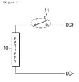
- a battery charging and discharging circuit in the related art is illustrated, and may control charging and discharging by using only one switch 11 connected with the battery in series on a charging and discharging path.
- the battery charging and discharging circuit in the related art blocks a charging current by opening the switch 11 when the overcharging occurs, thereby preventing overcharging.
- the discharging current cannot move due to the opening of the switch 11.
- the battery charging and discharging circuit in the related art blocks the discharging current by opening the switch 11 when the discharging occurs, thereby preventing the overdischarging.
- the charging current cannot also flow due to the opening of the switch 11.
- an object of the present invention is to provide a battery pack protection device and method, and more particularly, a battery pack protection device and method that can extend a battery lifespan by performing conversion for charging and discharging of the battery smoothly so as to be suitable for a current state and control properly a timing of charging and discharging by allowing a user to easily check a current charging and discharging state of the battery, by sensing an overcharging state or an overdischarging state of the battery and controlling a plurality of switches installed on a charging path and a discharging path of the battery.
- An exemplary embodiment of the present invention provides a battery pack protection device including: a sensing unit configured to sense an overcharging state or an overdischarging state of a battery; a plurality of switches installed on a charging path and a discharging path of the battery; and a control unit configured to control the plurality of switches so that the battery are both chargeable and dischargeable when the battery is not in the overcharging state or the overdischarging state and control the plurality of switches so that the battery is only dischargeable during overcharging or only chargeable during overdischarging by an output signal of the sensing unit.
- the battery pack protection device may further include a plurality of unidirectional elements on the charging path and the discharging path of the battery.
- the unidirectional elements may be diodes.
- the plurality of switches may include a first switch installed on the charging path and a second switch installed on the discharging path.
- the control unit may control the battery to be only dischargeable by opening the first switch and closing the second switch when the sensing unit senses the overcharging state.
- the control unit may control the battery to be only chargeable by closing the first switch and opening the second switch when the sensing unit senses the overdischarging state.
- the battery pack protection device may further include a display unit configured to display the charging state or the discharging state of the battery.
- the display unit may display the overcharging state when the sensing unit senses the overcharging state and display the overdischarging state when the sensing unit senses the overdischarging state.
- Another exemplary embodiment of the present invention provides a battery pack protection method including: sensing overcharging or overdischarging of a battery; controlling a plurality of switches so that the battery is both chargeable and dischargeable when the battery is not in an overcharging state or an overdischarging state; and controlling the plurality of switches so that the battery is only dischargeable during the overcharging or only chargeable during the overdischarging by an output signal of the sensing unit.
- the switches when the overcharging state of the battery is sensed in the sensing, the switches may be controlled so that the battery is only dischargeable by opening the first switch and closing the second switch.
- the switches when the overdischarging state of the battery is sensed in the sensing, the switches may be controlled so that the battery is only chargeable by closing the first switch and opening the second switch.
- the battery pack protection method may further include displaying the charging state or the discharging state of the battery.
- the overcharging state may be displayed when the overcharging state is sensed in the sensing, and the overdischarging state may be displayed when the overdischarging state is sensed in the sensing.
- a battery pack protection device and method and more particularly, a battery pack protection device and method that can extend a battery lifespan by performing conversion for charging and discharging of the battery smoothly so as to be suitable for a current state and control properly a timing of charging and discharging by allowing a user to easily check a current charging and discharging state of the battery, by sensing an overcharging state or an overdischarging state of the battery and controlling a plurality of switches installed on a charging path and a discharging path of the battery.
- unit means a unit for processing one or more functions or operations, and may be implemented with hardware or software, or in combination of the hardware and the software.
- an electric vehicle means a vehicle including one or more electric motors as driving force.
- Energy used to drive the electric vehicle includes an electrical source such as a rechargeable battery and/or fuel cell.
- the electric vehicle may be a hybrid electric vehicle using an internal combustion engine as another power source.
- FIG. 2 is a diagram schematically illustrating an electric vehicle to which a battery pack protection device 100 may be applied according to an exemplary embodiment of the present invention.
- the battery pack protection device 100 is applied to the electric vehicle, but the battery pack protection device according to the exemplary embodiment of the present invention may be applied to any technical field to which a secondary battery may be applied, such as an energy storage system (ESS) for household or industry or a uninterruptible power supply (UPS) system in addition to the electric vehicle.
- ESS energy storage system
- UPS uninterruptible power supply
- An electric vehicle 1 may include a battery 10, a battery management system (BMS) 20, an electronic control unit (ECU) 30, an inverter 40, and a motor 50.
- BMS battery management system
- ECU electronice control unit
- the battery 10 is an electric energy source which drives the electric vehicle 1 by supplying driving force to the motor 50.
- the battery 10 may be charged or discharged by the inverter 40 according to driving of the motor 50 and/or an internal combustion engine (not illustrated).
- a kind of battery 10 is not particularly limited, and for example, the battery 10 may be configured by a lithium-ion battery, a lithium polymer battery, a nickel cadmium battery, a nickel hydrogen battery, a nickel zinc battery, and the like.
- the battery 10 is formed as a battery pack in which a plurality of battery cells are connected with each other in series and/or in parallel.
- one or more battery packs are provided to form the battery 10.
- the BMS 20 estimates a state of the battery 10 and manages the battery 10 by using estimated state information. For example, the BMS 20 estimates and manages the state information of the battery 10, such as a state of charging (SOC), a state of health (SOH), a maximum input/output power allowance, and an output voltage of the battery 10. In addition, the BMS 20 controls charging or discharging of the battery 10 by using the state information, and furthermore, may estimate a replacement time of the battery 10.
- SOC state of charging
- SOH state of health
- the BMS 20 controls charging or discharging of the battery 10 by using the state information, and furthermore, may estimate a replacement time of the battery 10.
- the BMS 20 may include the battery pack protection device 100 according to the exemplary embodiment of the present invention to be described below.
- the battery pack protection device 100 By such a battery pack protection device 100, the charging and discharging of the battery 10 may be properly controlled, and the battery 10 may be protected during overcharging or overdischarging.
- the ECU 30 is an electronic control device controlling the state of the electric vehicle 1. For example, the ECU 30 determines a torque degree based on information such as an accelerator, a break, and a speed, and controls an output of the motor 50 to be suitable for the torque information.
- the ECU 30 transmits a control signal to the inverter 40 so that the battery 10 may be charged or discharged based on the state information such as the SOC and the SOH of the battery 10 which are received by the BMS 20.
- the inverter 40 allows the battery 10 to be charged or discharged based on the control signal of the ECU 30.
- the motor 50 drives the electric vehicle 1 based on the control information (for example, torque information) transferred from the ECU 30 by using the electric energy of the battery 10.
- control information for example, torque information
- the aforementioned electric vehicle 1 is driven by using the electric energy of the battery 10, it is important to exactly estimate the state of the battery 10, for example, the charging state, the discharging state, the overcharging state, and the overdischarging state.
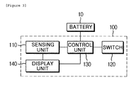
- FIG. 3 is a diagram illustrating a configuration of the battery pack protection device according to the exemplary embodiment of the present invention.
- the battery pack protection device 100 may include a sensing unit 110, a switch 120, a control unit 130, and a display unit 140.
- the battery pack protection device 100 illustrated in FIG. 3 is in accordance with the exemplary embodiment, constituent elements thereof are limited to the embodiment illustrated in FIG. 3 , and some constituent elements may be added, modified, or deleted if necessary.
- the sensing unit 110 senses the overcharging state or the overdischarging state of the battery 10.
- the sensing unit 110 may sense the overcharging state or the overdischarging state only in the case where the charging amount or the discharging amount is more or less than a predetermined reference value. For example, when the charging amount flowing into the battery 10 is 100% or more, the state may be determined as overcharging. Further, when the discharging amount flowing into the battery 10 is 90% or more or the charging amount is 10% or less, the state may be determined as overdischarging.
- the reference value may be a predetermined fixed value as an initial value in the sensing unit 110, and may be a value changed by receiving the input of the user.
- the switch 120 is a plurality of switches installed on the charging path and the discharging path of the battery 10.
- the switch 120 may include one or more of a limit switch, a relay switch, a proximity switch, a micro switch, and a photoelectric switch.
- the control unit 130 may control the switch 120 so that the battery 10 is both chargeable and dischargeable, and control the switch 120 so that the battery is only chargeable or only dischargeable by an output signal of the sensing unit 110.
- the control unit 130 may control the battery 10 to be only dischargeable by opening the switch positioned on the charging path and closing the switch positioned on the discharging path.
- the control unit 130 may control the battery 10 to be only chargeable by closing the switch positioned on the charging path and opening the switch positioned on the discharging path.
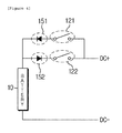
- FIG. 4 is a circuit diagram illustrating an example of a detailed configuration of the battery pack protection device 100 according to the exemplary embodiment of the present invention.
- the control unit 130 is not illustrated, but actually, the control unit 130 is connected to the switch 120 to control the switch 120.
- the switch 120 may include a first switch 121 installed on the charging path and a second switch 122 installed on the discharging path.
- the battery pack protection device 100 may further include a plurality of unidirectional elements 151 and 152 on the charging path and the discharging path, and for example, the unidirectional elements 151 and 152 may be diodes.
- the control unit 130 closes the first switch 121 installed on the charging path and closes the second switch 122 installed on the discharging path, and as a result, movement of the current is free, and the battery is both chargeable and dischargeable.
- the control unit 130 opens the first switch 121 installed on the charging path and closes the second switch 122 installed on the discharging path, the movement of the current to the charging path is limited by the unidirectional element, and the current is induced only to the discharging path.
- the display unit 140 may display the charging state or the discharging state of the battery 10.
- the display unit 140 may include one or more of a liquid crystal display (LCD) device, a light emitting diode (LED) device, a cathode-ray tube (CRT) device, a plasma display panel (PDP) device, and an organic light emitting diode (OLED) device.
- LCD liquid crystal display
- LED light emitting diode
- CRT cathode-ray tube
- PDP plasma display panel
- OLED organic light emitting diode
- the display unit 140 performing the aforementioned role is not limited to a kind of the described display device.
- the display unit 140 may display the overcharging state when the sensing unit 110 senses the overcharging state, and display the overdischarging state when the sensing unit 110 senses the overdischarging state.
- the display unit 140 may select and display one or more charging and discharging states when the sensing unit 110 senses the state. For example, the display unit 140 may display a voltage amount flowing into the battery 10, a charging amount, a discharging amount, a residual amount, charging and discharging states, or a current amount.
- FIG. 5 is a flowchart for describing a battery pack protection method according to another embodiment of the present invention.
- a battery pack protection method when a battery pack protection method according to another embodiment of the present invention starts, first, whether there is overcharging or overdischarging of the battery is sensed (S11), and whether the battery is in the overcharging state or the overdischarging state is determined (S12). Since the processes of the steps S11 and S12 follow the description for the sensing unit 110, the duplicated description will be omitted.
- the battery is both chargeable and dischargeable (S17). In this case, while both the switch (121 of FIG. 4 ) and the switch (122 of FIG. 4 ) are closed, the battery is freely chargeable and dischargeable.
- the battery is only dischargeable (S15) by opening the first switch (121 of FIG. 4 ) and closing the second switch (122 of FIG. 4 ) (S13).
- the battery is only chargeable (S16) by closing the first switch (121 of FIG. 4 ) and opening the second switch (122 of FIG. 4 ) (S14). Since the processes of the steps S13 and S14 follow the description for the control unit 130, the duplicated description will be omitted.
- the aforementioned battery pack protection method is described with reference to the flowchart illustrated in the drawing.
- the method is illustrated and described as a series of blocks, but the present invention is not limited to an order of the blocks, and some blocks may occur in a different order illustrated and described in this specification from or simultaneously with other blocks, and various other branches, flow paths, and orders of the blocks which achieve the same or a similar result may be implemented. Further, all of the blocks illustrated for implementing the method described in this specification may not be required.
Landscapes
- Engineering & Computer Science (AREA)
- Power Engineering (AREA)
- Secondary Cells (AREA)
- Charge And Discharge Circuits For Batteries Or The Like (AREA)
Applications Claiming Priority (2)
| Application Number | Priority Date | Filing Date | Title |
|---|---|---|---|
| KR1020130077181A KR101644217B1 (ko) | 2013-07-02 | 2013-07-02 | 배터리 팩 보호 장치 및 방법 |
| PCT/KR2014/004212 WO2015002379A1 (fr) | 2013-07-02 | 2014-05-12 | Dispositif et procédé de protection de bloc de batteries |
Publications (2)
| Publication Number | Publication Date |
|---|---|
| EP2889984A1 true EP2889984A1 (fr) | 2015-07-01 |
| EP2889984A4 EP2889984A4 (fr) | 2016-06-08 |
Family
ID=52143930
Family Applications (1)
| Application Number | Title | Priority Date | Filing Date |
|---|---|---|---|
| EP14820400.1A Ceased EP2889984A4 (fr) | 2013-07-02 | 2014-05-12 | Dispositif et procédé de protection de bloc de batteries |
Country Status (4)
| Country | Link |
|---|---|
| US (1) | US9774196B2 (fr) |
| EP (1) | EP2889984A4 (fr) |
| KR (1) | KR101644217B1 (fr) |
| WO (1) | WO2015002379A1 (fr) |
Cited By (2)
| Publication number | Priority date | Publication date | Assignee | Title |
|---|---|---|---|---|
| EP3296140A4 (fr) * | 2015-12-10 | 2018-10-03 | LG Chem, Ltd. | Système et procédé d'accès à une batterie |
| EP3413392B1 (fr) * | 2016-08-26 | 2025-06-25 | LG Energy Solution, Ltd. | Système de gestion de batterie |
Families Citing this family (6)
| Publication number | Priority date | Publication date | Assignee | Title |
|---|---|---|---|---|
| KR101910918B1 (ko) * | 2015-12-09 | 2018-10-23 | 현대자동차주식회사 | 차량 및 그 충전 제어방법 |
| TWI676334B (zh) * | 2017-10-19 | 2019-11-01 | 富晶電子股份有限公司 | 鋰電池充放電開關裝置及其控制方法 |
| KR102802132B1 (ko) * | 2019-02-20 | 2025-04-28 | 삼성에스디아이 주식회사 | 배터리 제어 장치 및 배터리 제어 방법 |
| JP7462838B2 (ja) | 2020-10-14 | 2024-04-05 | サムスン エレクトロニクス カンパニー リミテッド | バッテリの過放電状態に基づいて充電禁止及び/又はユーザインタフェースを提供する電子装置及びその制御方法 |
| WO2022080738A1 (fr) * | 2020-10-14 | 2022-04-21 | 삼성전자 주식회사 | Dispositif électronique pour fournir une interdiction de charge et/ou une interface utilisateur sur la base d'un état de décharge excessive de batterie, et son procédé de commande |
| KR20230061043A (ko) * | 2021-10-28 | 2023-05-08 | 주식회사 엘지에너지솔루션 | 배터리 팩의 충전가능범위 제공 기능을 갖는 파워뱅크 및 이를 포함하는 배터리 팩 충전 시스템과 그 방법 |
Family Cites Families (16)
| Publication number | Priority date | Publication date | Assignee | Title |
|---|---|---|---|---|
| US5789900A (en) | 1994-12-05 | 1998-08-04 | Fuji Photo Film Co., Ltd. | Device for protecting a secondary battery from overcharge and overdischarge |
| JPH10174298A (ja) | 1996-12-13 | 1998-06-26 | Matsushita Electric Ind Co Ltd | 充電型直流電源回路 |
| JPH11215716A (ja) | 1998-01-20 | 1999-08-06 | Matsushita Electric Ind Co Ltd | 電池管理装置,電池パック及び電子機器 |
| JP3380766B2 (ja) * | 1999-03-18 | 2003-02-24 | 富士通株式会社 | 保護方法及び制御回路並びに電池ユニット |
| US6501248B2 (en) * | 2000-09-28 | 2002-12-31 | Ricoh Company, Ltd. | Charge/discharge protection apparatus having a charge-state overcurrent detector, and battery pack including the same |
| JP2006101635A (ja) * | 2004-09-29 | 2006-04-13 | Mitsumi Electric Co Ltd | 過充電/過放電検出装置及び過充電/過放電検出回路並びに半導体装置 |
| KR100624944B1 (ko) | 2004-11-29 | 2006-09-18 | 삼성에스디아이 주식회사 | 배터리 팩의 보호회로 |
| US7436151B2 (en) * | 2004-12-23 | 2008-10-14 | Dell Products L.P. | Systems and methods for detecting charge switching element failure in a battery system |
| JP2006254650A (ja) | 2005-03-14 | 2006-09-21 | Mitsumi Electric Co Ltd | 電池保護回路 |
| JP4101816B2 (ja) * | 2005-05-16 | 2008-06-18 | 日本テキサス・インスツルメンツ株式会社 | バッテリ保護回路 |
| US7595619B2 (en) * | 2005-08-23 | 2009-09-29 | Texas Instruments Incorporated | Feed-forward circuit for adjustable output voltage controller circuits |
| JP2009089468A (ja) * | 2007-09-27 | 2009-04-23 | Panasonic Electric Works Co Ltd | 電池パック |
| JP2009089768A (ja) * | 2007-10-04 | 2009-04-30 | Nelson Precision Casting Co Ltd | ゴルフクラブヘッド及びその製造方法 |
| KR100943576B1 (ko) * | 2007-10-30 | 2010-02-23 | 삼성에스디아이 주식회사 | 배터리 팩 |
| KR20090126098A (ko) | 2008-06-03 | 2009-12-08 | 삼성에스디아이 주식회사 | 배터리 팩 및 그 충전 방법 |
| JP5990878B2 (ja) * | 2011-07-26 | 2016-09-14 | 株式会社Gsユアサ | 無停電電源装置及び電源装置 |
-
2013
- 2013-07-02 KR KR1020130077181A patent/KR101644217B1/ko active Active
-
2014
- 2014-05-12 EP EP14820400.1A patent/EP2889984A4/fr not_active Ceased
- 2014-05-12 WO PCT/KR2014/004212 patent/WO2015002379A1/fr not_active Ceased
- 2014-05-12 US US14/428,179 patent/US9774196B2/en active Active
Cited By (3)
| Publication number | Priority date | Publication date | Assignee | Title |
|---|---|---|---|---|
| EP3296140A4 (fr) * | 2015-12-10 | 2018-10-03 | LG Chem, Ltd. | Système et procédé d'accès à une batterie |
| US10266056B2 (en) | 2015-12-10 | 2019-04-23 | Lg Chem, Ltd. | Battery access system and method |
| EP3413392B1 (fr) * | 2016-08-26 | 2025-06-25 | LG Energy Solution, Ltd. | Système de gestion de batterie |
Also Published As
| Publication number | Publication date |
|---|---|
| US9774196B2 (en) | 2017-09-26 |
| WO2015002379A1 (fr) | 2015-01-08 |
| US20150256006A1 (en) | 2015-09-10 |
| KR101644217B1 (ko) | 2016-07-29 |
| KR20150004117A (ko) | 2015-01-12 |
| EP2889984A4 (fr) | 2016-06-08 |
Similar Documents
| Publication | Publication Date | Title |
|---|---|---|
| US9774196B2 (en) | Battery pack protection device and method | |
| KR101921641B1 (ko) | 배터리 제어 장치 및 방법 | |
| EP2523248B1 (fr) | Dispositif et procédé de commande de batterie | |
| RU2569676C1 (ru) | Система управления зарядом аккумулятора для автоматически управляемого транспортного средства и способ управления зарядом аккумулятора для автоматически управляемого транспортного средства | |
| JP5943404B2 (ja) | バッテリースウェリング感知装置および方法 | |
| KR20140029800A (ko) | 배터리 관리 시스템 | |
| KR20170013537A (ko) | 배터리 관리와 통신기능을 갖는 에너지 저장 및 제어시스템 | |
| KR20160137493A (ko) | 전압 측정을 통한 배터리 랙 파손 방지 장치, 시스템 및 방법 | |
| KR102734327B1 (ko) | 차량용 배터리 시스템 및 그 제어방법 | |
| KR101641762B1 (ko) | 프리차지 저항 및 릴레이 파손 방지 장치 및 방법 | |
| CN103296726A (zh) | 电池储能模组及其控制方法和储能供电系统 | |
| KR20120077482A (ko) | 배터리 모듈의 균등 충전장치 | |
| EP3675319A1 (fr) | Bloc-batterie et dispositif électronique le comprenant | |
| KR20160132691A (ko) | 전기 이동 수단 및 그 제어 방법 | |
| KR102717608B1 (ko) | 배터리 관리 시스템 및 이의 제어방법, 및 이를 포함하는 배터리 팩 | |
| KR20220131445A (ko) | 전기자동차의 충전 장치 및 방법 | |
| Kilic et al. | Design of master and slave modules on battery management system for electric vehicles | |
| CN106300279B (zh) | 用于二次电池过放电后的强制充电保护电路 | |
| US11588189B2 (en) | Battery control method | |
| KR101091387B1 (ko) | 만충전 용량 비교를 통한 배터리 보호 장치 및 방법 | |
| JP2019519191A (ja) | バッテリー逆電圧防止システム及び方法 | |
| KR20160067600A (ko) | 배터리 셀 과충전 보호 장치 및 방법 | |
| KR101542283B1 (ko) | 이차 전지의 충전 보호 장치, 충전기 및 전지 팩 | |
| KR102686777B1 (ko) | 배터리 관리 시스템 및 방법 | |
| AU2024351939A1 (en) | A rechargeable battery pack and method of use thereof |
Legal Events
| Date | Code | Title | Description |
|---|---|---|---|
| PUAI | Public reference made under article 153(3) epc to a published international application that has entered the european phase |
Free format text: ORIGINAL CODE: 0009012 |
|
| 17P | Request for examination filed |
Effective date: 20150324 |
|
| AK | Designated contracting states |
Kind code of ref document: A1 Designated state(s): AL AT BE BG CH CY CZ DE DK EE ES FI FR GB GR HR HU IE IS IT LI LT LU LV MC MK MT NL NO PL PT RO RS SE SI SK SM TR |
|
| AX | Request for extension of the european patent |
Extension state: BA ME |
|
| RA4 | Supplementary search report drawn up and despatched (corrected) |
Effective date: 20160511 |
|
| RIC1 | Information provided on ipc code assigned before grant |
Ipc: H02J 7/04 20060101AFI20160504BHEP Ipc: H02J 7/00 20060101ALI20160504BHEP |
|
| DAX | Request for extension of the european patent (deleted) | ||
| 17Q | First examination report despatched |
Effective date: 20170717 |
|
| REG | Reference to a national code |
Ref country code: DE Ref legal event code: R003 |
|
| STAA | Information on the status of an ep patent application or granted ep patent |
Free format text: STATUS: THE APPLICATION HAS BEEN REFUSED |
|
| 18R | Application refused |
Effective date: 20190516 |