EP2889877B1 - Seismic isolation assembly - Google Patents
Seismic isolation assembly Download PDFInfo
- Publication number
- EP2889877B1 EP2889877B1 EP14194009.8A EP14194009A EP2889877B1 EP 2889877 B1 EP2889877 B1 EP 2889877B1 EP 14194009 A EP14194009 A EP 14194009A EP 2889877 B1 EP2889877 B1 EP 2889877B1
- Authority
- EP
- European Patent Office
- Prior art keywords
- support plate
- linear
- dampers
- wire rope
- recited
- Prior art date
- Legal status (The legal status is an assumption and is not a legal conclusion. Google has not performed a legal analysis and makes no representation as to the accuracy of the status listed.)
- Active
Links
Images


Classifications
-
- E—FIXED CONSTRUCTIONS
- E04—BUILDING
- E04H—BUILDINGS OR LIKE STRUCTURES FOR PARTICULAR PURPOSES; SWIMMING OR SPLASH BATHS OR POOLS; MASTS; FENCING; TENTS OR CANOPIES, IN GENERAL
- E04H9/00—Buildings, groups of buildings or shelters adapted to withstand or provide protection against abnormal external influences, e.g. war-like action, earthquake or extreme climate
- E04H9/02—Buildings, groups of buildings or shelters adapted to withstand or provide protection against abnormal external influences, e.g. war-like action, earthquake or extreme climate withstanding earthquake or sinking of ground
- E04H9/021—Bearing, supporting or connecting constructions specially adapted for such buildings
- E04H9/0235—Anti-seismic devices with hydraulic or pneumatic damping
-
- E—FIXED CONSTRUCTIONS
- E04—BUILDING
- E04H—BUILDINGS OR LIKE STRUCTURES FOR PARTICULAR PURPOSES; SWIMMING OR SPLASH BATHS OR POOLS; MASTS; FENCING; TENTS OR CANOPIES, IN GENERAL
- E04H9/00—Buildings, groups of buildings or shelters adapted to withstand or provide protection against abnormal external influences, e.g. war-like action, earthquake or extreme climate
- E04H9/02—Buildings, groups of buildings or shelters adapted to withstand or provide protection against abnormal external influences, e.g. war-like action, earthquake or extreme climate withstanding earthquake or sinking of ground
- E04H9/021—Bearing, supporting or connecting constructions specially adapted for such buildings
- E04H9/0215—Bearing, supporting or connecting constructions specially adapted for such buildings involving active or passive dynamic mass damping systems
-
- E—FIXED CONSTRUCTIONS
- E02—HYDRAULIC ENGINEERING; FOUNDATIONS; SOIL SHIFTING
- E02D—FOUNDATIONS; EXCAVATIONS; EMBANKMENTS; UNDERGROUND OR UNDERWATER STRUCTURES
- E02D27/00—Foundations as substructures
- E02D27/32—Foundations for special purposes
- E02D27/34—Foundations for sinking or earthquake territories
-
- E—FIXED CONSTRUCTIONS
- E02—HYDRAULIC ENGINEERING; FOUNDATIONS; SOIL SHIFTING
- E02D—FOUNDATIONS; EXCAVATIONS; EMBANKMENTS; UNDERGROUND OR UNDERWATER STRUCTURES
- E02D27/00—Foundations as substructures
- E02D27/32—Foundations for special purposes
- E02D27/42—Foundations for poles, masts or chimneys
-
- E—FIXED CONSTRUCTIONS
- E04—BUILDING
- E04H—BUILDINGS OR LIKE STRUCTURES FOR PARTICULAR PURPOSES; SWIMMING OR SPLASH BATHS OR POOLS; MASTS; FENCING; TENTS OR CANOPIES, IN GENERAL
- E04H12/00—Towers; Masts or poles; Chimney stacks; Water-towers; Methods of erecting such structures
- E04H12/22—Sockets or holders for poles or posts
-
- F—MECHANICAL ENGINEERING; LIGHTING; HEATING; WEAPONS; BLASTING
- F16—ENGINEERING ELEMENTS AND UNITS; GENERAL MEASURES FOR PRODUCING AND MAINTAINING EFFECTIVE FUNCTIONING OF MACHINES OR INSTALLATIONS; THERMAL INSULATION IN GENERAL
- F16F—SPRINGS; SHOCK-ABSORBERS; MEANS FOR DAMPING VIBRATION
- F16F15/00—Suppression of vibrations in systems; Means or arrangements for avoiding or reducing out-of-balance forces, e.g. due to motion
- F16F15/02—Suppression of vibrations of non-rotating, e.g. reciprocating systems; Suppression of vibrations of rotating systems by use of members not moving with the rotating systems
- F16F15/022—Suppression of vibrations of non-rotating, e.g. reciprocating systems; Suppression of vibrations of rotating systems by use of members not moving with the rotating systems using dampers and springs in combination
-
- F—MECHANICAL ENGINEERING; LIGHTING; HEATING; WEAPONS; BLASTING
- F16—ENGINEERING ELEMENTS AND UNITS; GENERAL MEASURES FOR PRODUCING AND MAINTAINING EFFECTIVE FUNCTIONING OF MACHINES OR INSTALLATIONS; THERMAL INSULATION IN GENERAL
- F16F—SPRINGS; SHOCK-ABSORBERS; MEANS FOR DAMPING VIBRATION
- F16F15/00—Suppression of vibrations in systems; Means or arrangements for avoiding or reducing out-of-balance forces, e.g. due to motion
- F16F15/02—Suppression of vibrations of non-rotating, e.g. reciprocating systems; Suppression of vibrations of rotating systems by use of members not moving with the rotating systems
- F16F15/04—Suppression of vibrations of non-rotating, e.g. reciprocating systems; Suppression of vibrations of rotating systems by use of members not moving with the rotating systems using elastic means
- F16F15/06—Suppression of vibrations of non-rotating, e.g. reciprocating systems; Suppression of vibrations of rotating systems by use of members not moving with the rotating systems using elastic means with metal springs
-
- F—MECHANICAL ENGINEERING; LIGHTING; HEATING; WEAPONS; BLASTING
- F16—ENGINEERING ELEMENTS AND UNITS; GENERAL MEASURES FOR PRODUCING AND MAINTAINING EFFECTIVE FUNCTIONING OF MACHINES OR INSTALLATIONS; THERMAL INSULATION IN GENERAL
- F16F—SPRINGS; SHOCK-ABSORBERS; MEANS FOR DAMPING VIBRATION
- F16F7/00—Vibration-dampers; Shock-absorbers
- F16F7/14—Vibration-dampers; Shock-absorbers of cable support type, i.e. frictionally-engaged loop-forming cables
-
- G—PHYSICS
- G10—MUSICAL INSTRUMENTS; ACOUSTICS
- G10K—SOUND-PRODUCING DEVICES; METHODS OR DEVICES FOR PROTECTING AGAINST, OR FOR DAMPING, NOISE OR OTHER ACOUSTIC WAVES IN GENERAL; ACOUSTICS NOT OTHERWISE PROVIDED FOR
- G10K11/00—Methods or devices for transmitting, conducting or directing sound in general; Methods or devices for protecting against, or for damping, noise or other acoustic waves in general
- G10K11/16—Methods or devices for protecting against, or for damping, noise or other acoustic waves in general
-
- F—MECHANICAL ENGINEERING; LIGHTING; HEATING; WEAPONS; BLASTING
- F16—ENGINEERING ELEMENTS AND UNITS; GENERAL MEASURES FOR PRODUCING AND MAINTAINING EFFECTIVE FUNCTIONING OF MACHINES OR INSTALLATIONS; THERMAL INSULATION IN GENERAL
- F16F—SPRINGS; SHOCK-ABSORBERS; MEANS FOR DAMPING VIBRATION
- F16F2222/00—Special physical effects, e.g. nature of damping effects
- F16F2222/12—Fluid damping
-
- F—MECHANICAL ENGINEERING; LIGHTING; HEATING; WEAPONS; BLASTING
- F16—ENGINEERING ELEMENTS AND UNITS; GENERAL MEASURES FOR PRODUCING AND MAINTAINING EFFECTIVE FUNCTIONING OF MACHINES OR INSTALLATIONS; THERMAL INSULATION IN GENERAL
- F16F—SPRINGS; SHOCK-ABSORBERS; MEANS FOR DAMPING VIBRATION
- F16F2230/00—Purpose; Design features
- F16F2230/0023—Purpose; Design features protective
-
- F—MECHANICAL ENGINEERING; LIGHTING; HEATING; WEAPONS; BLASTING
- F16—ENGINEERING ELEMENTS AND UNITS; GENERAL MEASURES FOR PRODUCING AND MAINTAINING EFFECTIVE FUNCTIONING OF MACHINES OR INSTALLATIONS; THERMAL INSULATION IN GENERAL
- F16F—SPRINGS; SHOCK-ABSORBERS; MEANS FOR DAMPING VIBRATION
- F16F2236/00—Mode of stressing of basic spring or damper elements or devices incorporating such elements
- F16F2236/04—Compression
-
- F—MECHANICAL ENGINEERING; LIGHTING; HEATING; WEAPONS; BLASTING
- F16—ENGINEERING ELEMENTS AND UNITS; GENERAL MEASURES FOR PRODUCING AND MAINTAINING EFFECTIVE FUNCTIONING OF MACHINES OR INSTALLATIONS; THERMAL INSULATION IN GENERAL
- F16F—SPRINGS; SHOCK-ABSORBERS; MEANS FOR DAMPING VIBRATION
- F16F2238/00—Type of springs or dampers
- F16F2238/04—Damper
Definitions
- This application is directed generally to the field of isolation assemblies and more specifically to a seismic isolation assembly for use with ground supported structures, including tall and eccentrically defined structures.
- Ground supported structures or apparatus are susceptible to various forms of loading, including seismic and environmental load inputs, among others, over their useful life.
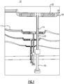
- a supported structure is a circuit breaker for use in an electrical power grid assembly, shown in Fig. 1 .
- This structure 10 is defined by a vertical mast 14 that supports an upper horizontally disposed cross member 18, the latter being configured for connection to a plurality of high tension lines 17.
- the length of the vertical mast 14 is considerably longer than that of the horizontal member 18, the latter being supported at the top of the vertical member 14 and therefore producing a high center of gravity (CG) that can also be eccentrically disposed in relation to the lower or bottom end of the structure 10 at which the structure is supported.
- CG center of gravity
- the herein described structure 10 further includes a plurality of ceramic insulator disc-like plates 22 that are disposed in a sequential or stacked configuration axially along at least portions of each of the vertical mast 14 and horizontal cross member 18.
- these ceramic insulator plates 22 may become more susceptible to cracking and fracture, which adversely affects performance.
- the time taken to inspect these structures for damage following a seismic event and the additional cost and time impact required for repair and replacement can be significant.
- WO 2012/152826 A1 shows a vessel in which a container-bearing base is associated with a supporting base by means of a shock-filtering setpoint damping means.
- DE 10 2006 054 274 B3 discloses a 3-axis spring damping system comprising spring damping elements and twistable torsion bars.
- a further vibration damping device with a first base body, a second base body and a curved member arranged in between is disclosed in JP 2012 246 998 A .
- an assembly for seismically isolating a structure according to claim 1.
- the first and second support plates are horizontally disposed with the first support plate being disposed beneath the second support plate.
- the wire rope isolators are attached to the underside of the second support plate and to a support block that is fixedly attached to the base.
- the linear dampers include a linearly or axially movable end attached to the second support plate and an opposite end attached to a support that is fixedly mounted to the base.
- the linear dampers can accordingly to one embodiment be comprised of viscous based dampers, such as hydraulic dampers, that provide the additional damping for multi-directional load inputs from a supported structure.
- sets of linear dampers can be disposed between evenly distributed wire rope isolators.
- Each set of linear dampers can include at least one of a plurality of dampers commonly disposed at an angle of between approximately 90 and 45 degrees relative to the second support plate.
- multiple sets, each including at least two viscous dampers are inwardly disposed at an angle between the upper and lower support plates. In one version, this angle is approximately 20 degrees from vertical.
- each wire rope isolator is disposed in spaced relation between the upper and lower support plates.
- a corresponding number of sets of linear dampers are additionally disposed, with a set being mounted between each of adjacently spaced wire rope isolators and about the outer periphery of the support plates.
- Each set of linear dampers can include two or more linear dampers commonly and inwardly disposed from a base mounted support toward the end of the second support plate at the disposed angle.
- the linear dampers are viscous and in which the first and second support plates are provided along a horizontal plane with the wire rope isolators being configured horizontally between the support plates and in which at least one linear damper is vertically disposed relative to the assembly between each of the wire rope isolators.
- Sets of linear dampers such as hydraulic or other viscous dampers, can be commonly and vertically disposed at a predetermined angle between the wire rope isolators.
- sets of two or more linear dampers can be mounted to the second support plate and the base in side by side relation to provide additional damping.
- One advantage provided by the herein described seismic isolation assembly is that additional damping can be provided to a supported ground structure having a high CG and/or eccentric configuration and capable of producing a multi-dimensional load input, which can produce rocking of the structure.
- Another advantage is that the herein described seismic isolation assembly is reliable and less prone to hysteresis effects.
- Yet another advantage is that the number of linear dampers can easily be adjusted as needed to change the damping characteristics of the herein described system and permitting versatility as to numerous ground structures and loading conditions.
- an exemplary seismic isolation assembly 100 includes a first or lower support plate 104 and a second or upper support plate 110.
- Each of the lower and upper support plates 104, 110 are made from a suitable structural material, such as stainless steel, and disposed in substantially parallel relation with one another.
- the perspective view of Fig. 2 shows that the lower support plate 104 is attached, such through the use of bolts (not shown) secured through openings 105 extending through the thickness of the lower support plate 104 to a support structure on the ground.
- a spacing 117 is defined between an upper surface or side 109 of the lower support plate 104 and a lower surface or side 111 of the upper support plate 110, as discussed herein.
- the lower support plate 104 is substantially rectangular in terms of configuration, with each corner 107 of the lower support plate 104 being beveled.
- the upper support plate 110 is smaller in terms of its overall length and width dimensions than that of the lower support plate 104.
- the upper support plate 110 is further defined by a substantially octagonal shape defined by respective sides 115. It should be noted, however, that the herein described configuration is exemplary and other suitable polygonal shapes, including circular configurations, could be alternatively provided for either or both of the lower and upper support plates 104, 110, provided each are substantially planar.
- the upper support plate 110 When assembled, the upper support plate 110 is substantially centered above the lower support plate 104, the support plates being disposed in a substantially horizontal configuration.
- a top or upper side 112 of the upper support plate 110 includes at least one set of openings 119 that are spaced and configured for fixedly and securely retaining an end of the structure to be isolated.
- each wire rope isolator 118 is individually secured to the lower surface 111 of the upper support plate 110 and to the upper surface of a support block or platform 127, the latter being bolted or otherwise fixedly mounted to the upper surface 109 of the lower support plate 104.
- the support block 127 is exemplary and other mounting techniques to the lower support surface 104 or the base 113 can be utilized.
- a total of four (4) wire rope isolators 118 are disposed in equally spaced relation to one another between the lower and upper support plates 104, 110, although this parameter can also be easily varied depending on loading conditions and the structure to be isolated.
- each wire rope isolator 118 includes a rectangular shaped upper mounting block 130 and a parallel and correspondingly shaped lower mounting block 134, respectively.
- a plurality of cylindrical wire coils 140 are introduced between the mounting blocks 130, 134 through a spaced series of lateral holes 144 provided in each mounting block 130, 134, as the coils 140 are threaded therethrough and in which the ends of each coil 140 are attached to the upper mounting block 130.
- the mounting blocks 130, 134 are each formed from aluminum and the cylindrical wire coils 140 are formed from stainless steel, but these materials can be suitably varied.
- the size of the mounting blocks 130, 134 and the lateral holes 144 of the isolators 118, as well as the thickness of the cylindrical wire in the coils 140 used can also be suitably varied, depending on the structure being supported and required spring rate, deflection and damping characteristics of a particular application.
- one suitable wire rope isolator design which can be used for this purpose is described in commonly owned U.S. Patent No. 5,449,285 to Collins . It will be readily apparent from the following discussion that other suitable isolator assemblies can be alternatively used.
- Each of the mounting blocks 130, 134 of the wire rope isolators 118 further includes a set of equally spaced transverse through openings 152 that are provided in opposing top and bottom sides thereof to permit attachment to the bottom surface 111 of the upper support plate 110 and the top surface of the supporting block 127, respectively, using appropriately sized threaded fasteners.
- the herein described isolation assembly further includes an additional plurality of linear dampers 160 that are disposed between the lower support plate 104 and the upper support plate 110. These dampers 160 provide additional damping that cannot be provided by the wire rope isolators 118 due to loading conditions of the supported structure 10, Fig. 1 .
- each of the linear dampers 160 are defined by a cylindrical housing 168 having a fixed end 164 and an oppositely disposed axially movable end 166.
- the axially movable end 166 is further attached to a piston assembly 174 that includes a piston rod 176 extending within the interior of the cylindrical housing 168.
- the interior of the cylindrical housing 168 defines a damping chamber that is configured to retain a quantity of a hydraulic fluid and in which the piston assembly 174 is configured to displace fluid within the cylinder and induce damping.
- Each of the movable and fixed ends 164, 166 of the cylinder 168 include fittings that enable transverse mounting.
- the stroke of the piston assembly 174 can be selected based on the loading characteristics and structure to be supported and isolated.
- a suitable hydraulic damper for these purposes is the LD damper series, manufactured by ITT Enidine, Inc., although other versions can be substituted.
- each of the four sets of linear dampers 160 include a plurality of hydraulic viscous dampers in which each fixed end 164 is independently secured to the lower support plate 104 and the movable end 166 is secured to an upwardly extending portion of a mounting block 190, the latter being fixedly attached to the top surface 112 of the upper support plate 110 and secured thereto using bolts or other suitable fasteners (not shown).
- Each of the linear dampers 160 according to this particular embodiment are vertically disposed at an angle of approximately 68 degrees relative to the upper support plate 110.
- each set of linear dampers 160 is defined by four (4) hydraulic dampers, which are disposed in side by side parallel relation to one another and independently mounted to the lower support plate 104 and mounting block 190.
- the number of sets of linear dampers 160 and the number of dampers in each set can be varied, as well as the vertical angle at which the linear dampers 160 are disposed.
- the number of dampers 160 can be changed "on the fly" for purposes of testing and support/damping in actual use and in which the support block 127 and mounting plate can include a plurality of spaced attachment positions.
- each linear damper 160 can be suitably selected based on the loading characteristics, as well as the type of hydraulic fluid retained in the housing 168 and the damping coefficient.
- the circuit breaker of Fig. 1 is again shown having a supporting vertical bracket 15 disposed at the lower or bottom end of the structure 10 that is fixedly mounted to the upper side 112 of the upper support plate 110 while the lower support plate 104 is attached to ground.
- This supported structure 10 is isolated from seismic inputs from the ground, which is a multi-directional input. Based on the high and/or eccentric center of gravity of the supported structure a rocking component is created, which is non-axial.
- the wire rope isolators 118 providing a low spring rate and some hysteretic damping in all directions.
- the linear dampers 160 being angularly mounted relative to the primary axis of the supported structure 10 are configured to provide additional damping to the system in all directions. That is, angular mounting of a plurality of linear dampers 160 at the spaced locations enables additional damping as caused by seismic loads in all directions.
- the hydraulic damping is required because the wire rope isolators 118 fail to provide sufficient damping in all directions.
Landscapes
- Engineering & Computer Science (AREA)
- General Engineering & Computer Science (AREA)
- Architecture (AREA)
- Structural Engineering (AREA)
- Environmental & Geological Engineering (AREA)
- Civil Engineering (AREA)
- Mechanical Engineering (AREA)
- Business, Economics & Management (AREA)
- Emergency Management (AREA)
- Physics & Mathematics (AREA)
- Acoustics & Sound (AREA)
- Aviation & Aerospace Engineering (AREA)
- Life Sciences & Earth Sciences (AREA)
- General Life Sciences & Earth Sciences (AREA)
- Mining & Mineral Resources (AREA)
- Paleontology (AREA)
- Multimedia (AREA)
- Vibration Prevention Devices (AREA)
- Buildings Adapted To Withstand Abnormal External Influences (AREA)
Priority Applications (1)
| Application Number | Priority Date | Filing Date | Title |
|---|---|---|---|
| PL14194009T PL2889877T3 (pl) | 2013-12-06 | 2014-11-20 | Zespół izolacji sejsmicznej |
Applications Claiming Priority (1)
| Application Number | Priority Date | Filing Date | Title |
|---|---|---|---|
| US201361913035P | 2013-12-06 | 2013-12-06 |
Publications (2)
| Publication Number | Publication Date |
|---|---|
| EP2889877A1 EP2889877A1 (en) | 2015-07-01 |
| EP2889877B1 true EP2889877B1 (en) | 2021-03-10 |
Family
ID=51932249
Family Applications (1)
| Application Number | Title | Priority Date | Filing Date |
|---|---|---|---|
| EP14194009.8A Active EP2889877B1 (en) | 2013-12-06 | 2014-11-20 | Seismic isolation assembly |
Country Status (5)
| Country | Link |
|---|---|
| US (2) | US9255399B2 (pl) |
| EP (1) | EP2889877B1 (pl) |
| CL (1) | CL2014003245A1 (pl) |
| ES (1) | ES2872931T3 (pl) |
| PL (1) | PL2889877T3 (pl) |
Families Citing this family (31)
| Publication number | Priority date | Publication date | Assignee | Title |
|---|---|---|---|---|
| SI2933815T1 (sl) * | 2014-04-17 | 2019-07-31 | Terna Rete Italia S.P.A. | Seizmična izolacijska naprava za stikalo takšne vrste, ki se uporablja pri električnih sistemih visoke napetosti |
| CN103924705B (zh) * | 2014-04-23 | 2015-06-10 | 华南理工大学建筑设计研究院 | 一种适应结构隔震抗风的变刚度隔震层刚度控制机构 |
| US20150345900A1 (en) * | 2014-05-28 | 2015-12-03 | Chief Of Naval Research, Office Of Counsel | Missile Launcher System |
| JP6614815B2 (ja) * | 2014-06-16 | 2019-12-04 | ユニバーシティー プトラ マレーシア | 可変剛性補強器具 |
| WO2016046104A1 (en) * | 2014-09-24 | 2016-03-31 | Siemens Aktiengesellschaft | Damping and support device for electrical equipments |
| JP6787643B2 (ja) * | 2015-08-21 | 2020-11-18 | Thk株式会社 | 上下免震装置 |
| US10283837B2 (en) | 2015-10-23 | 2019-05-07 | Viasat, Inc. | Apparatuses for mounting an antenna assembly |
| IT201600127545A1 (it) * | 2016-12-16 | 2018-06-16 | Nuovo Pignone Tecnologie Srl | Sistema di montaggio per macchine rotanti |
| CN106812866B (zh) * | 2017-01-12 | 2018-10-02 | 中国航空工业集团公司北京航空材料研究院 | 一种三自由度无角位移抗冲击平台 |
| CN106815027B (zh) * | 2017-01-22 | 2020-06-09 | 山东鲁能软件技术有限公司 | 一种用于电网多维业务复合计算的高弹性计算平台 |
| US11002031B2 (en) | 2017-02-16 | 2021-05-11 | Koroneho Limited | Base isolation system |
| CN109211510A (zh) * | 2017-07-06 | 2019-01-15 | 中国船舶重工集团公司第七〇四研究所 | 一种测量系统抗冲击供电平台 |
| CN108839947A (zh) * | 2018-05-11 | 2018-11-20 | 丁保明 | 一种减震效果好的机器人用包装装置 |
| CN209082841U (zh) * | 2018-09-12 | 2019-07-09 | 刘容彰 | 屋顶绿化、防风抑震装置及建筑物 |
| US11732495B2 (en) * | 2018-12-21 | 2023-08-22 | Esm Energie-Und Schwingungstechnik Mitsch Gmbh | Impulse tuned mass damper for tall, slim structures |
| CN109996417B (zh) * | 2019-02-20 | 2023-10-20 | 和信精密科技(吴江)有限公司 | 一种可拆式server |
| CN110360411B (zh) * | 2019-06-24 | 2021-02-26 | 江苏精工泵业有限公司 | 一种用于混流泵的减震基座 |
| CN110588496A (zh) * | 2019-09-25 | 2019-12-20 | 重庆真测科技股份有限公司 | 一种车载工业ct/dr系统主机减振系统 |
| KR102262326B1 (ko) * | 2020-01-01 | 2021-06-10 | 한국철도기술연구원 | 화물 컨테이너 방진장치 |
| JP7465702B2 (ja) * | 2020-03-30 | 2024-04-11 | 株式会社フジタ | 免震装置および設計方法 |
| US11313145B2 (en) * | 2020-09-15 | 2022-04-26 | Cal Poly Corporation | Earthquake protection systems, methods and apparatus using shape memory alloy (SMA)-based superelasticity-assisted slider (SSS) |
| CN112177415B (zh) * | 2020-10-12 | 2022-08-05 | 同济大学 | 一种环形多方向布置的tmd系统 |
| WO2022113567A1 (ja) * | 2020-11-27 | 2022-06-02 | 国立大学法人大阪大学 | 免震用鋼材ダンパー及び免震構造 |
| CN112594326B (zh) * | 2020-12-16 | 2022-08-12 | 河南铸盾人防工程安装有限公司 | 一种用于组合大屏幕的隔震系统 |
| WO2023043415A1 (en) * | 2021-09-14 | 2023-03-23 | Bogazici Universitesi | Vibration isolation system adjustable in three axes |
| TR2021021812A1 (tr) * | 2021-12-30 | 2023-07-21 | Boğazi̇çi̇ Üni̇versi̇tesi̇ | Üç eksende sifira yakin ayarlanabi̇li̇r di̇rengenli̇ğe sahi̇p çok gerdi̇rme telli̇ yatay ti̇treşi̇m yalitim si̇stemi̇ |
| CN115538496A (zh) * | 2022-10-24 | 2022-12-30 | 孙俊 | 高压输电塔基础的抗震装置 |
| CN115653380B (zh) * | 2022-12-19 | 2023-03-10 | 中国电建集团山东电力建设第一工程有限公司 | 一种用于输电塔的模块化耗能装配式结构 |
| TR2023003739A2 (tr) * | 2023-04-05 | 2023-06-21 | Roketsan Roket Sanayi Ve Ticaret Anonim Sirketi | Çeli̇k sarmal halat ti̇pi̇ sönümleme elemanlarina sahi̇p bi̇r kani̇ster taşima si̇stemi̇ |
| CN116576217B (zh) * | 2023-05-15 | 2025-10-14 | 同济大学 | 一种限制位移的高竖向承载力钢丝绳阻尼器 |
| CN117359650B (zh) * | 2023-08-29 | 2024-07-05 | 江苏建科土木工程技术有限公司 | 基于耦合加载机构的建筑缆索加载力主动控制方法 |
Citations (1)
| Publication number | Priority date | Publication date | Assignee | Title |
|---|---|---|---|---|
| US20110094488A1 (en) * | 2008-04-08 | 2011-04-28 | Rheinmetall Waffe Munition Gmbh | Stabilizing device |
Family Cites Families (60)
| Publication number | Priority date | Publication date | Assignee | Title |
|---|---|---|---|---|
| US3794277A (en) * | 1972-08-14 | 1974-02-26 | A Smedley | Earthquake resistant support |
| US4108270A (en) | 1977-02-09 | 1978-08-22 | Exxon Production Research Company | Hydraulic stabilization system to position and isolate a seismic vibrator |
| US4858738A (en) * | 1978-07-26 | 1989-08-22 | Fernando Novoa | System of auxiliary mass dampers to restrain the response of slender elastic structures to vibrations such as from earthquakes |
| EP0027195B1 (en) | 1979-10-11 | 1985-08-07 | Eaton-Optimetrix Inc. | Improved shock and vibration isolation system |
| US4336917A (en) | 1979-10-11 | 1982-06-29 | Optimetrix Corporation | Shock and vibration isolation system |
| US5042024A (en) * | 1989-04-28 | 1991-08-20 | Pioneer Electronic Corporation | Disk reproduction apparatus capable of being disposed in different attitudes |
| JPH086493B2 (ja) | 1991-05-29 | 1996-01-24 | 鹿島建設株式会社 | 構造物の振動制御装置 |
| US5169110A (en) * | 1991-07-18 | 1992-12-08 | Aeroflex International Incorporated | Force-damping energy-removing isolator |
| US5360210A (en) | 1991-12-16 | 1994-11-01 | Vectra Technologies, Inc. | Pipe restraint |
| US5791636A (en) | 1992-07-16 | 1998-08-11 | Loziuk; Larry | Compact profile wire cable isolator and energy absorbing restraint |
| US5441243A (en) | 1992-07-16 | 1995-08-15 | Vectra Technologies, Inc. | Wire cable isolator and energy absorbing restraint |
| IT226869Z2 (it) | 1992-08-20 | 1997-07-22 | Camossi Carlo | Dispositivo elastico a cavo metallico ed antivibrazione per il supporto di un gruppo rotante |
| IT1262385B (it) * | 1993-08-03 | 1996-06-19 | Tis Tech Idraulico Stradali | Dispersore di energia meccanico multidirezionale particolarmente adatto per il vincolo di strutture in zona sismica. |
| US5449285A (en) | 1994-03-29 | 1995-09-12 | Davidson Textron, Inc. | Mold for molding a resin to form a complex article |
| US5559671A (en) | 1994-06-30 | 1996-09-24 | Hughes Aircraft Company | BI-directional shock isolation mounting system and method |
| US5549285A (en) | 1995-04-21 | 1996-08-27 | Enidine, Inc. | Wire rope isolator with crimp bar and method for making same |
| US5797227A (en) | 1996-04-09 | 1998-08-25 | Garza-Tamez; Federico | Structure stabilization system |
| DE29610411U1 (de) | 1996-06-13 | 1996-08-14 | Siemens AG, 80333 München | Elektronisches Gerät mit Massenspeicher |
| IT1294130B1 (it) | 1997-05-15 | 1999-03-22 | Electrolux Zanussi Elettrodome | Metodo per realizzare uno smorzamento attivo delle vibrazioni dovute al gruppo lavante e macchina lavatrice per attuare tale |
| US6286805B1 (en) | 1998-07-01 | 2001-09-11 | Clear Vision Laser Centers, Inc. | Apparatus and method for transporting equipment between buildings |
| DE19859897C1 (de) | 1998-12-23 | 2000-08-10 | Knorr Bremse Systeme | Vorrichtung zur schwingungsdämpfenden Lagerung einer Drucklufterzeugungsanlage an einem Befestigungsträger eines Schienenfahrzeugs |
| US6098966A (en) * | 1999-04-19 | 2000-08-08 | Enidine Incorporated | Apparatus for absorbing shock and attenuating vibrations |
| US6406011B1 (en) | 2000-02-02 | 2002-06-18 | Enidine Incorporated | Wire rope isolator with pinned bar and method for making same |
| US6244579B1 (en) | 2000-02-02 | 2001-06-12 | Enidine, Incorporated | Light press manufactured (LPM) wire rope isolator and method of manufacture |
| US6290217B1 (en) | 2000-03-29 | 2001-09-18 | Enidine Incorporated | Asymmetric wire rope isolator |
| US6530563B1 (en) * | 2001-07-10 | 2003-03-11 | Enidine, Incorporated | Multi-axis shock and vibration isolation system |
| US20030016996A1 (en) | 2001-07-23 | 2003-01-23 | Gelfand Matthew A. | Energy absorbing system |
| US20030132077A1 (en) * | 2002-01-15 | 2003-07-17 | Davis Toren S. | Tuned mass damper using a hexapod |
| KR101012914B1 (ko) | 2002-02-07 | 2011-02-08 | 유니버설 세이프티 리스폰스, 인크. | 에너지 흡수 시스템 |
| NL1022035C2 (nl) * | 2002-11-29 | 2004-06-07 | Thales Nederland Bv | Elementaire en complexe koppelinrichtingen, en de gebruiksmogelijkheden ervan. |
| US7070177B2 (en) * | 2003-02-18 | 2006-07-04 | Arvinmeritor Technology, Llc | Sandwich design of four bag suspension for bus and coach rear drive axles |
| US7337586B2 (en) | 2004-06-14 | 2008-03-04 | Chi-Chang Lin | Anti-seismic device with vibration-reducing units arranged in parallel |
| US20070258861A1 (en) | 2004-06-15 | 2007-11-08 | Barket Dennis Jr | Analytical Instruments, Assemblies, and Methods |
| IL164229A (en) * | 2004-09-22 | 2010-05-17 | Rafael Advanced Defense Sys | Vibration damping pylon |
| US7108111B2 (en) | 2004-10-25 | 2006-09-19 | Enidine Incorporated | Semi-active isolator |
| US7325792B2 (en) | 2005-03-11 | 2008-02-05 | Enidine, Inc. | Multi-axial base isolation system |
| US20060201759A1 (en) | 2005-03-11 | 2006-09-14 | Enidine, Inc. | Isolation cabinet |
| US7487958B2 (en) * | 2005-05-10 | 2009-02-10 | Shu-Lung Wang | Anti-vibration mechanism for dental impression material mixer |
| JP2007039894A (ja) | 2005-08-01 | 2007-02-15 | Shimizu Corp | スカフォード用緩衝保持装置 |
| US7852274B2 (en) | 2005-12-16 | 2010-12-14 | Rockwell Collins Satellite Communications Systems, Inc. | Communications trailer |
| WO2008022466A1 (en) | 2006-08-25 | 2008-02-28 | March Networks Corporation | Mobile event data recorder with multiple orientation vibration isolation |
| DE102006054274B3 (de) * | 2006-11-17 | 2007-12-27 | Astrium Gmbh | 3-Achsen Feder-Dämpfungssystem |
| US7837380B2 (en) * | 2006-12-26 | 2010-11-23 | Shu-Lung Wang | Guarding structure for a mixer of molding material |
| CN101641482B (zh) * | 2007-03-23 | 2012-08-08 | 株式会社小松制作所 | 防振装置 |
| NO330721B1 (no) | 2008-03-11 | 2011-06-20 | Techni As | Dempeanordning |
| US8444121B2 (en) | 2008-03-31 | 2013-05-21 | Honeywell International Inc. | Systems for damping vibrations from a payload |
| SG172145A1 (en) | 2008-12-15 | 2011-07-28 | Sea Tel Inc | Pedestal for tracking antenna |
| CN101882460B (zh) | 2009-05-08 | 2012-07-04 | 中国船舶重工集团公司第七0四研究所 | 钢丝绳式计算机硬盘隔振器 |
| US8235351B1 (en) | 2009-08-27 | 2012-08-07 | Lockheed Martin Corporation | Shock load isolation mounting |
| JP5570605B2 (ja) * | 2009-09-25 | 2014-08-13 | ファウ・エス・エル・インターナツイオナール・アクチエンゲゼルシヤフト | 建物内の運動を減衰するための方法および構造 |
| ES2401365T3 (es) | 2009-11-20 | 2013-04-19 | Eads Deutschland Gmbh | Estructura de aislamiento de choques |
| ES2404879T3 (es) | 2010-06-02 | 2013-05-29 | Thales Nederland B.V. | Dispositivo para aislar un objeto de movimientos externos |
| US8919714B2 (en) | 2010-10-13 | 2014-12-30 | Re2, Inc. | Compliant tool holder |
| US8480052B2 (en) * | 2011-01-11 | 2013-07-09 | Drs Tactical Systems, Inc. | Vibration isolating device |
| CN201971165U (zh) | 2011-03-28 | 2011-09-14 | 广州市红鹏直升机遥感科技有限公司 | 航拍云台减震装置 |
| FR2975074B1 (fr) * | 2011-05-11 | 2013-06-21 | Dcns | Navire du type comportant au moins un puits de reception d'au moins un conteneur de lancement de missile |
| JP2012246998A (ja) * | 2011-05-27 | 2012-12-13 | Tanaka Seishin Kozo Kenkyusho:Kk | 制振装置 |
| US9127744B2 (en) * | 2012-07-05 | 2015-09-08 | Chapman/Leonard Studio Equipment, Inc. | Camera isolator with adjustable dampening |
| US20140305334A1 (en) * | 2013-04-12 | 2014-10-16 | Electro-Motive Diesel, Inc. | Mounting structure for driving unit and driven unit of locomotive |
| CN103410605B (zh) * | 2013-08-20 | 2015-12-02 | 武汉海王科技有限公司 | 一种1e级柴油发电机组 |
-
2014
- 2014-11-20 PL PL14194009T patent/PL2889877T3/pl unknown
- 2014-11-20 EP EP14194009.8A patent/EP2889877B1/en active Active
- 2014-11-20 ES ES14194009T patent/ES2872931T3/es active Active
- 2014-11-28 CL CL2014003245A patent/CL2014003245A1/es unknown
- 2014-12-04 US US14/560,817 patent/US9255399B2/en active Active
-
2016
- 2016-01-14 US US14/995,314 patent/US9809975B2/en active Active
Patent Citations (1)
| Publication number | Priority date | Publication date | Assignee | Title |
|---|---|---|---|---|
| US20110094488A1 (en) * | 2008-04-08 | 2011-04-28 | Rheinmetall Waffe Munition Gmbh | Stabilizing device |
Also Published As
| Publication number | Publication date |
|---|---|
| US9255399B2 (en) | 2016-02-09 |
| US20160130805A1 (en) | 2016-05-12 |
| EP2889877A1 (en) | 2015-07-01 |
| CL2014003245A1 (es) | 2015-11-20 |
| ES2872931T3 (es) | 2021-11-03 |
| US9809975B2 (en) | 2017-11-07 |
| US20150159370A1 (en) | 2015-06-11 |
| PL2889877T3 (pl) | 2021-09-20 |
| NZ702029A (en) | 2018-03-23 |
Similar Documents
| Publication | Publication Date | Title |
|---|---|---|
| EP2889877B1 (en) | Seismic isolation assembly | |
| US5595371A (en) | Vibration isolating supporter | |
| CN107110281B (zh) | 用于模块化的工业设备的安装系统 | |
| KR101384027B1 (ko) | 지진저감용 면진 모듈 | |
| JP5149155B2 (ja) | 収納ラック振動絶縁装置及び関連する収納ラックシステム | |
| EP3177850B1 (en) | Damping and support device for electrical equipments | |
| EP2821668B1 (en) | Vibration-insulating device and system | |
| KR101362926B1 (ko) | 와이어로프 방진기 및 이것을 이용한 방진 시스템 | |
| KR20170060208A (ko) | 내진 보강 장치 | |
| KR101701810B1 (ko) | 내진장치 | |
| KR102881813B1 (ko) | 수전반 및 배전반 | |
| KR20160074571A (ko) | 베어링 | |
| US7267010B2 (en) | Inertial mass guided single axis vibration test machine | |
| RU2537984C1 (ru) | Тарельчатый виброизолятор кочетова с демпфером сухого трения | |
| NZ702029B (en) | Seismic isolation assembly | |
| US7090207B2 (en) | Single-end-mount seismic isolator | |
| CN204721764U (zh) | 一种逆变器机柜中的变压器放置结构、逆变器机柜 | |
| US5624104A (en) | Vibration isolating supporter | |
| JP7068145B2 (ja) | 減衰付加装置および減衰付加方法 | |
| RU2551574C1 (ru) | Виброизолятор шайбовый сетчатый кочетова | |
| RU2661669C1 (ru) | Виброизолятор пространственный | |
| RU2636439C1 (ru) | Пакет кольцевых пружин | |
| Brancati et al. | A seismic isolation system for lightweight structures based on MRE devices | |
| RU148481U1 (ru) | Виброизолятор | |
| JP2020085038A (ja) | モジュール支持構造体及び電気システム |
Legal Events
| Date | Code | Title | Description |
|---|---|---|---|
| PUAI | Public reference made under article 153(3) epc to a published international application that has entered the european phase |
Free format text: ORIGINAL CODE: 0009012 |
|
| 17P | Request for examination filed |
Effective date: 20141120 |
|
| AK | Designated contracting states |
Kind code of ref document: A1 Designated state(s): AL AT BE BG CH CY CZ DE DK EE ES FI FR GB GR HR HU IE IS IT LI LT LU LV MC MK MT NL NO PL PT RO RS SE SI SK SM TR |
|
| AX | Request for extension of the european patent |
Extension state: BA ME |
|
| R17P | Request for examination filed (corrected) |
Effective date: 20160104 |
|
| RBV | Designated contracting states (corrected) |
Designated state(s): AL AT BE BG CH CY CZ DE DK EE ES FI FR GB GR HR HU IE IS IT LI LT LU LV MC MK MT NL NO PL PT RO RS SE SI SK SM TR |
|
| STAA | Information on the status of an ep patent application or granted ep patent |
Free format text: STATUS: EXAMINATION IS IN PROGRESS |
|
| 17Q | First examination report despatched |
Effective date: 20190711 |
|
| REG | Reference to a national code |
Ref country code: DE Ref legal event code: R079 Ref document number: 602014075515 Country of ref document: DE Free format text: PREVIOUS MAIN CLASS: G10K0011160000 Ipc: E02D0027340000 |
|
| GRAP | Despatch of communication of intention to grant a patent |
Free format text: ORIGINAL CODE: EPIDOSNIGR1 |
|
| STAA | Information on the status of an ep patent application or granted ep patent |
Free format text: STATUS: GRANT OF PATENT IS INTENDED |
|
| RIC1 | Information provided on ipc code assigned before grant |
Ipc: F16F 7/14 20060101ALI20201103BHEP Ipc: F16F 15/02 20060101ALI20201103BHEP Ipc: E02D 27/34 20060101AFI20201103BHEP Ipc: G10K 11/16 20060101ALI20201103BHEP |
|
| INTG | Intention to grant announced |
Effective date: 20201204 |
|
| GRAS | Grant fee paid |
Free format text: ORIGINAL CODE: EPIDOSNIGR3 |
|
| GRAA | (expected) grant |
Free format text: ORIGINAL CODE: 0009210 |
|
| STAA | Information on the status of an ep patent application or granted ep patent |
Free format text: STATUS: THE PATENT HAS BEEN GRANTED |
|
| AK | Designated contracting states |
Kind code of ref document: B1 Designated state(s): AL AT BE BG CH CY CZ DE DK EE ES FI FR GB GR HR HU IE IS IT LI LT LU LV MC MK MT NL NO PL PT RO RS SE SI SK SM TR |
|
| REG | Reference to a national code |
Ref country code: GB Ref legal event code: FG4D |
|
| REG | Reference to a national code |
Ref country code: AT Ref legal event code: REF Ref document number: 1369933 Country of ref document: AT Kind code of ref document: T Effective date: 20210315 Ref country code: CH Ref legal event code: EP |
|
| REG | Reference to a national code |
Ref country code: DE Ref legal event code: R096 Ref document number: 602014075515 Country of ref document: DE |
|
| REG | Reference to a national code |
Ref country code: IE Ref legal event code: FG4D |
|
| REG | Reference to a national code |
Ref country code: NL Ref legal event code: FP |
|
| REG | Reference to a national code |
Ref country code: LT Ref legal event code: MG9D |
|
| PG25 | Lapsed in a contracting state [announced via postgrant information from national office to epo] |
Ref country code: NO Free format text: LAPSE BECAUSE OF FAILURE TO SUBMIT A TRANSLATION OF THE DESCRIPTION OR TO PAY THE FEE WITHIN THE PRESCRIBED TIME-LIMIT Effective date: 20210610 Ref country code: BG Free format text: LAPSE BECAUSE OF FAILURE TO SUBMIT A TRANSLATION OF THE DESCRIPTION OR TO PAY THE FEE WITHIN THE PRESCRIBED TIME-LIMIT Effective date: 20210610 Ref country code: GR Free format text: LAPSE BECAUSE OF FAILURE TO SUBMIT A TRANSLATION OF THE DESCRIPTION OR TO PAY THE FEE WITHIN THE PRESCRIBED TIME-LIMIT Effective date: 20210611 Ref country code: HR Free format text: LAPSE BECAUSE OF FAILURE TO SUBMIT A TRANSLATION OF THE DESCRIPTION OR TO PAY THE FEE WITHIN THE PRESCRIBED TIME-LIMIT Effective date: 20210310 Ref country code: FI Free format text: LAPSE BECAUSE OF FAILURE TO SUBMIT A TRANSLATION OF THE DESCRIPTION OR TO PAY THE FEE WITHIN THE PRESCRIBED TIME-LIMIT Effective date: 20210310 Ref country code: LT Free format text: LAPSE BECAUSE OF FAILURE TO SUBMIT A TRANSLATION OF THE DESCRIPTION OR TO PAY THE FEE WITHIN THE PRESCRIBED TIME-LIMIT Effective date: 20210310 |
|
| REG | Reference to a national code |
Ref country code: AT Ref legal event code: MK05 Ref document number: 1369933 Country of ref document: AT Kind code of ref document: T Effective date: 20210310 |
|
| PG25 | Lapsed in a contracting state [announced via postgrant information from national office to epo] |
Ref country code: SE Free format text: LAPSE BECAUSE OF FAILURE TO SUBMIT A TRANSLATION OF THE DESCRIPTION OR TO PAY THE FEE WITHIN THE PRESCRIBED TIME-LIMIT Effective date: 20210310 Ref country code: RS Free format text: LAPSE BECAUSE OF FAILURE TO SUBMIT A TRANSLATION OF THE DESCRIPTION OR TO PAY THE FEE WITHIN THE PRESCRIBED TIME-LIMIT Effective date: 20210310 Ref country code: LV Free format text: LAPSE BECAUSE OF FAILURE TO SUBMIT A TRANSLATION OF THE DESCRIPTION OR TO PAY THE FEE WITHIN THE PRESCRIBED TIME-LIMIT Effective date: 20210310 |
|
| PG25 | Lapsed in a contracting state [announced via postgrant information from national office to epo] |
Ref country code: CZ Free format text: LAPSE BECAUSE OF FAILURE TO SUBMIT A TRANSLATION OF THE DESCRIPTION OR TO PAY THE FEE WITHIN THE PRESCRIBED TIME-LIMIT Effective date: 20210310 Ref country code: EE Free format text: LAPSE BECAUSE OF FAILURE TO SUBMIT A TRANSLATION OF THE DESCRIPTION OR TO PAY THE FEE WITHIN THE PRESCRIBED TIME-LIMIT Effective date: 20210310 Ref country code: AT Free format text: LAPSE BECAUSE OF FAILURE TO SUBMIT A TRANSLATION OF THE DESCRIPTION OR TO PAY THE FEE WITHIN THE PRESCRIBED TIME-LIMIT Effective date: 20210310 Ref country code: SM Free format text: LAPSE BECAUSE OF FAILURE TO SUBMIT A TRANSLATION OF THE DESCRIPTION OR TO PAY THE FEE WITHIN THE PRESCRIBED TIME-LIMIT Effective date: 20210310 |
|
| REG | Reference to a national code |
Ref country code: ES Ref legal event code: FG2A Ref document number: 2872931 Country of ref document: ES Kind code of ref document: T3 Effective date: 20211103 |
|
| PG25 | Lapsed in a contracting state [announced via postgrant information from national office to epo] |
Ref country code: IS Free format text: LAPSE BECAUSE OF FAILURE TO SUBMIT A TRANSLATION OF THE DESCRIPTION OR TO PAY THE FEE WITHIN THE PRESCRIBED TIME-LIMIT Effective date: 20210710 Ref country code: SK Free format text: LAPSE BECAUSE OF FAILURE TO SUBMIT A TRANSLATION OF THE DESCRIPTION OR TO PAY THE FEE WITHIN THE PRESCRIBED TIME-LIMIT Effective date: 20210310 Ref country code: RO Free format text: LAPSE BECAUSE OF FAILURE TO SUBMIT A TRANSLATION OF THE DESCRIPTION OR TO PAY THE FEE WITHIN THE PRESCRIBED TIME-LIMIT Effective date: 20210310 Ref country code: PT Free format text: LAPSE BECAUSE OF FAILURE TO SUBMIT A TRANSLATION OF THE DESCRIPTION OR TO PAY THE FEE WITHIN THE PRESCRIBED TIME-LIMIT Effective date: 20210712 |
|
| REG | Reference to a national code |
Ref country code: DE Ref legal event code: R097 Ref document number: 602014075515 Country of ref document: DE |
|
| PLBE | No opposition filed within time limit |
Free format text: ORIGINAL CODE: 0009261 |
|
| STAA | Information on the status of an ep patent application or granted ep patent |
Free format text: STATUS: NO OPPOSITION FILED WITHIN TIME LIMIT |
|
| PG25 | Lapsed in a contracting state [announced via postgrant information from national office to epo] |
Ref country code: DK Free format text: LAPSE BECAUSE OF FAILURE TO SUBMIT A TRANSLATION OF THE DESCRIPTION OR TO PAY THE FEE WITHIN THE PRESCRIBED TIME-LIMIT Effective date: 20210310 Ref country code: AL Free format text: LAPSE BECAUSE OF FAILURE TO SUBMIT A TRANSLATION OF THE DESCRIPTION OR TO PAY THE FEE WITHIN THE PRESCRIBED TIME-LIMIT Effective date: 20210310 |
|
| 26N | No opposition filed |
Effective date: 20211213 |
|
| PG25 | Lapsed in a contracting state [announced via postgrant information from national office to epo] |
Ref country code: SI Free format text: LAPSE BECAUSE OF FAILURE TO SUBMIT A TRANSLATION OF THE DESCRIPTION OR TO PAY THE FEE WITHIN THE PRESCRIBED TIME-LIMIT Effective date: 20210310 |
|
| PG25 | Lapsed in a contracting state [announced via postgrant information from national office to epo] |
Ref country code: IS Free format text: LAPSE BECAUSE OF FAILURE TO SUBMIT A TRANSLATION OF THE DESCRIPTION OR TO PAY THE FEE WITHIN THE PRESCRIBED TIME-LIMIT Effective date: 20210710 |
|
| PG25 | Lapsed in a contracting state [announced via postgrant information from national office to epo] |
Ref country code: MC Free format text: LAPSE BECAUSE OF FAILURE TO SUBMIT A TRANSLATION OF THE DESCRIPTION OR TO PAY THE FEE WITHIN THE PRESCRIBED TIME-LIMIT Effective date: 20210310 |
|
| REG | Reference to a national code |
Ref country code: CH Ref legal event code: PL |
|
| REG | Reference to a national code |
Ref country code: NL Ref legal event code: MM Effective date: 20211201 |
|
| PG25 | Lapsed in a contracting state [announced via postgrant information from national office to epo] |
Ref country code: LU Free format text: LAPSE BECAUSE OF NON-PAYMENT OF DUE FEES Effective date: 20211120 Ref country code: BE Free format text: LAPSE BECAUSE OF NON-PAYMENT OF DUE FEES Effective date: 20211130 |
|
| REG | Reference to a national code |
Ref country code: BE Ref legal event code: MM Effective date: 20211130 |
|
| PG25 | Lapsed in a contracting state [announced via postgrant information from national office to epo] |
Ref country code: LI Free format text: LAPSE BECAUSE OF NON-PAYMENT OF DUE FEES Effective date: 20211130 Ref country code: CH Free format text: LAPSE BECAUSE OF NON-PAYMENT OF DUE FEES Effective date: 20211130 |
|
| PG25 | Lapsed in a contracting state [announced via postgrant information from national office to epo] |
Ref country code: NL Free format text: LAPSE BECAUSE OF NON-PAYMENT OF DUE FEES Effective date: 20211201 |
|
| PG25 | Lapsed in a contracting state [announced via postgrant information from national office to epo] |
Ref country code: IE Free format text: LAPSE BECAUSE OF NON-PAYMENT OF DUE FEES Effective date: 20211120 |
|
| PG25 | Lapsed in a contracting state [announced via postgrant information from national office to epo] |
Ref country code: HU Free format text: LAPSE BECAUSE OF FAILURE TO SUBMIT A TRANSLATION OF THE DESCRIPTION OR TO PAY THE FEE WITHIN THE PRESCRIBED TIME-LIMIT; INVALID AB INITIO Effective date: 20141120 |
|
| PG25 | Lapsed in a contracting state [announced via postgrant information from national office to epo] |
Ref country code: CY Free format text: LAPSE BECAUSE OF FAILURE TO SUBMIT A TRANSLATION OF THE DESCRIPTION OR TO PAY THE FEE WITHIN THE PRESCRIBED TIME-LIMIT Effective date: 20210310 |
|
| P01 | Opt-out of the competence of the unified patent court (upc) registered |
Effective date: 20230528 |
|
| PGFP | Annual fee paid to national office [announced via postgrant information from national office to epo] |
Ref country code: GB Payment date: 20231019 Year of fee payment: 10 |
|
| PGFP | Annual fee paid to national office [announced via postgrant information from national office to epo] |
Ref country code: ES Payment date: 20231201 Year of fee payment: 10 |
|
| PGFP | Annual fee paid to national office [announced via postgrant information from national office to epo] |
Ref country code: IT Payment date: 20231019 Year of fee payment: 10 Ref country code: FR Payment date: 20231019 Year of fee payment: 10 Ref country code: DE Payment date: 20231019 Year of fee payment: 10 |
|
| PGFP | Annual fee paid to national office [announced via postgrant information from national office to epo] |
Ref country code: PL Payment date: 20231020 Year of fee payment: 10 |
|
| PG25 | Lapsed in a contracting state [announced via postgrant information from national office to epo] |
Ref country code: MK Free format text: LAPSE BECAUSE OF FAILURE TO SUBMIT A TRANSLATION OF THE DESCRIPTION OR TO PAY THE FEE WITHIN THE PRESCRIBED TIME-LIMIT Effective date: 20210310 |
|
| PG25 | Lapsed in a contracting state [announced via postgrant information from national office to epo] |
Ref country code: TR Free format text: LAPSE BECAUSE OF FAILURE TO SUBMIT A TRANSLATION OF THE DESCRIPTION OR TO PAY THE FEE WITHIN THE PRESCRIBED TIME-LIMIT Effective date: 20210310 |
|
| PG25 | Lapsed in a contracting state [announced via postgrant information from national office to epo] |
Ref country code: MT Free format text: LAPSE BECAUSE OF FAILURE TO SUBMIT A TRANSLATION OF THE DESCRIPTION OR TO PAY THE FEE WITHIN THE PRESCRIBED TIME-LIMIT Effective date: 20210310 |
|
| REG | Reference to a national code |
Ref country code: DE Ref legal event code: R119 Ref document number: 602014075515 Country of ref document: DE |
|
| GBPC | Gb: european patent ceased through non-payment of renewal fee |
Effective date: 20241120 |
|
| PG25 | Lapsed in a contracting state [announced via postgrant information from national office to epo] |
Ref country code: DE Free format text: LAPSE BECAUSE OF NON-PAYMENT OF DUE FEES Effective date: 20250603 |
|
| PG25 | Lapsed in a contracting state [announced via postgrant information from national office to epo] |
Ref country code: IT Free format text: LAPSE BECAUSE OF NON-PAYMENT OF DUE FEES Effective date: 20241120 |
|
| PG25 | Lapsed in a contracting state [announced via postgrant information from national office to epo] |
Ref country code: GB Free format text: LAPSE BECAUSE OF NON-PAYMENT OF DUE FEES Effective date: 20241120 |
|
| PG25 | Lapsed in a contracting state [announced via postgrant information from national office to epo] |
Ref country code: FR Free format text: LAPSE BECAUSE OF NON-PAYMENT OF DUE FEES Effective date: 20241130 |
|
| REG | Reference to a national code |
Ref country code: ES Ref legal event code: FD2A Effective date: 20260107 |
|
| PG25 | Lapsed in a contracting state [announced via postgrant information from national office to epo] |
Ref country code: ES Free format text: LAPSE BECAUSE OF NON-PAYMENT OF DUE FEES Effective date: 20241121 |