EP2889877A1 - Seismic isolation assembly - Google Patents
Seismic isolation assembly Download PDFInfo
- Publication number
- EP2889877A1 EP2889877A1 EP14194009.8A EP14194009A EP2889877A1 EP 2889877 A1 EP2889877 A1 EP 2889877A1 EP 14194009 A EP14194009 A EP 14194009A EP 2889877 A1 EP2889877 A1 EP 2889877A1
- Authority
- EP
- European Patent Office
- Prior art keywords
- dampers
- support plate
- recited
- disposed
- wire rope
- Prior art date
- Legal status (The legal status is an assumption and is not a legal conclusion. Google has not performed a legal analysis and makes no representation as to the accuracy of the status listed.)
- Granted
Links
- 238000002955 isolation Methods 0.000 title claims abstract description 23
- 238000000034 method Methods 0.000 claims description 12
- 238000013016 damping Methods 0.000 description 16
- 230000000712 assembly Effects 0.000 description 4
- 238000000429 assembly Methods 0.000 description 4
- 239000012530 fluid Substances 0.000 description 3
- 239000000919 ceramic Substances 0.000 description 2
- 230000005484 gravity Effects 0.000 description 2
- 239000012212 insulator Substances 0.000 description 2
- 239000000463 material Substances 0.000 description 2
- 229910001220 stainless steel Inorganic materials 0.000 description 2
- 239000010935 stainless steel Substances 0.000 description 2
- 230000002411 adverse Effects 0.000 description 1
- XAGFODPZIPBFFR-UHFFFAOYSA-N aluminium Chemical compound [Al] XAGFODPZIPBFFR-UHFFFAOYSA-N 0.000 description 1
- 229910052782 aluminium Inorganic materials 0.000 description 1
- 238000005336 cracking Methods 0.000 description 1
- 230000000694 effects Effects 0.000 description 1
- 230000007613 environmental effect Effects 0.000 description 1
- 238000012986 modification Methods 0.000 description 1
- 230000004048 modification Effects 0.000 description 1
- 230000000717 retained effect Effects 0.000 description 1
Images


Classifications
-
- E—FIXED CONSTRUCTIONS
- E04—BUILDING
- E04H—BUILDINGS OR LIKE STRUCTURES FOR PARTICULAR PURPOSES; SWIMMING OR SPLASH BATHS OR POOLS; MASTS; FENCING; TENTS OR CANOPIES, IN GENERAL
- E04H9/00—Buildings, groups of buildings or shelters adapted to withstand or provide protection against abnormal external influences, e.g. war-like action, earthquake or extreme climate
- E04H9/02—Buildings, groups of buildings or shelters adapted to withstand or provide protection against abnormal external influences, e.g. war-like action, earthquake or extreme climate withstanding earthquake or sinking of ground
- E04H9/021—Bearing, supporting or connecting constructions specially adapted for such buildings
- E04H9/0235—Anti-seismic devices with hydraulic or pneumatic damping
-
- E—FIXED CONSTRUCTIONS
- E04—BUILDING
- E04H—BUILDINGS OR LIKE STRUCTURES FOR PARTICULAR PURPOSES; SWIMMING OR SPLASH BATHS OR POOLS; MASTS; FENCING; TENTS OR CANOPIES, IN GENERAL
- E04H9/00—Buildings, groups of buildings or shelters adapted to withstand or provide protection against abnormal external influences, e.g. war-like action, earthquake or extreme climate
- E04H9/02—Buildings, groups of buildings or shelters adapted to withstand or provide protection against abnormal external influences, e.g. war-like action, earthquake or extreme climate withstanding earthquake or sinking of ground
- E04H9/021—Bearing, supporting or connecting constructions specially adapted for such buildings
- E04H9/0215—Bearing, supporting or connecting constructions specially adapted for such buildings involving active or passive dynamic mass damping systems
-
- E—FIXED CONSTRUCTIONS
- E02—HYDRAULIC ENGINEERING; FOUNDATIONS; SOIL SHIFTING
- E02D—FOUNDATIONS; EXCAVATIONS; EMBANKMENTS; UNDERGROUND OR UNDERWATER STRUCTURES
- E02D27/00—Foundations as substructures
- E02D27/32—Foundations for special purposes
- E02D27/34—Foundations for sinking or earthquake territories
-
- E—FIXED CONSTRUCTIONS
- E02—HYDRAULIC ENGINEERING; FOUNDATIONS; SOIL SHIFTING
- E02D—FOUNDATIONS; EXCAVATIONS; EMBANKMENTS; UNDERGROUND OR UNDERWATER STRUCTURES
- E02D27/00—Foundations as substructures
- E02D27/32—Foundations for special purposes
- E02D27/42—Foundations for poles, masts or chimneys
-
- E—FIXED CONSTRUCTIONS
- E04—BUILDING
- E04H—BUILDINGS OR LIKE STRUCTURES FOR PARTICULAR PURPOSES; SWIMMING OR SPLASH BATHS OR POOLS; MASTS; FENCING; TENTS OR CANOPIES, IN GENERAL
- E04H12/00—Towers; Masts or poles; Chimney stacks; Water-towers; Methods of erecting such structures
- E04H12/22—Sockets or holders for poles or posts
-
- F—MECHANICAL ENGINEERING; LIGHTING; HEATING; WEAPONS; BLASTING
- F16—ENGINEERING ELEMENTS AND UNITS; GENERAL MEASURES FOR PRODUCING AND MAINTAINING EFFECTIVE FUNCTIONING OF MACHINES OR INSTALLATIONS; THERMAL INSULATION IN GENERAL
- F16F—SPRINGS; SHOCK-ABSORBERS; MEANS FOR DAMPING VIBRATION
- F16F15/00—Suppression of vibrations in systems; Means or arrangements for avoiding or reducing out-of-balance forces, e.g. due to motion
- F16F15/02—Suppression of vibrations of non-rotating, e.g. reciprocating systems; Suppression of vibrations of rotating systems by use of members not moving with the rotating systems
- F16F15/022—Suppression of vibrations of non-rotating, e.g. reciprocating systems; Suppression of vibrations of rotating systems by use of members not moving with the rotating systems using dampers and springs in combination
-
- F—MECHANICAL ENGINEERING; LIGHTING; HEATING; WEAPONS; BLASTING
- F16—ENGINEERING ELEMENTS AND UNITS; GENERAL MEASURES FOR PRODUCING AND MAINTAINING EFFECTIVE FUNCTIONING OF MACHINES OR INSTALLATIONS; THERMAL INSULATION IN GENERAL
- F16F—SPRINGS; SHOCK-ABSORBERS; MEANS FOR DAMPING VIBRATION
- F16F15/00—Suppression of vibrations in systems; Means or arrangements for avoiding or reducing out-of-balance forces, e.g. due to motion
- F16F15/02—Suppression of vibrations of non-rotating, e.g. reciprocating systems; Suppression of vibrations of rotating systems by use of members not moving with the rotating systems
- F16F15/04—Suppression of vibrations of non-rotating, e.g. reciprocating systems; Suppression of vibrations of rotating systems by use of members not moving with the rotating systems using elastic means
- F16F15/06—Suppression of vibrations of non-rotating, e.g. reciprocating systems; Suppression of vibrations of rotating systems by use of members not moving with the rotating systems using elastic means with metal springs
-
- F—MECHANICAL ENGINEERING; LIGHTING; HEATING; WEAPONS; BLASTING
- F16—ENGINEERING ELEMENTS AND UNITS; GENERAL MEASURES FOR PRODUCING AND MAINTAINING EFFECTIVE FUNCTIONING OF MACHINES OR INSTALLATIONS; THERMAL INSULATION IN GENERAL
- F16F—SPRINGS; SHOCK-ABSORBERS; MEANS FOR DAMPING VIBRATION
- F16F7/00—Vibration-dampers; Shock-absorbers
- F16F7/14—Vibration-dampers; Shock-absorbers of cable support type, i.e. frictionally-engaged loop-forming cables
-
- G—PHYSICS
- G10—MUSICAL INSTRUMENTS; ACOUSTICS
- G10K—SOUND-PRODUCING DEVICES; METHODS OR DEVICES FOR PROTECTING AGAINST, OR FOR DAMPING, NOISE OR OTHER ACOUSTIC WAVES IN GENERAL; ACOUSTICS NOT OTHERWISE PROVIDED FOR
- G10K11/00—Methods or devices for transmitting, conducting or directing sound in general; Methods or devices for protecting against, or for damping, noise or other acoustic waves in general
- G10K11/16—Methods or devices for protecting against, or for damping, noise or other acoustic waves in general
-
- F—MECHANICAL ENGINEERING; LIGHTING; HEATING; WEAPONS; BLASTING
- F16—ENGINEERING ELEMENTS AND UNITS; GENERAL MEASURES FOR PRODUCING AND MAINTAINING EFFECTIVE FUNCTIONING OF MACHINES OR INSTALLATIONS; THERMAL INSULATION IN GENERAL
- F16F—SPRINGS; SHOCK-ABSORBERS; MEANS FOR DAMPING VIBRATION
- F16F2222/00—Special physical effects, e.g. nature of damping effects
- F16F2222/12—Fluid damping
-
- F—MECHANICAL ENGINEERING; LIGHTING; HEATING; WEAPONS; BLASTING
- F16—ENGINEERING ELEMENTS AND UNITS; GENERAL MEASURES FOR PRODUCING AND MAINTAINING EFFECTIVE FUNCTIONING OF MACHINES OR INSTALLATIONS; THERMAL INSULATION IN GENERAL
- F16F—SPRINGS; SHOCK-ABSORBERS; MEANS FOR DAMPING VIBRATION
- F16F2230/00—Purpose; Design features
- F16F2230/0023—Purpose; Design features protective
-
- F—MECHANICAL ENGINEERING; LIGHTING; HEATING; WEAPONS; BLASTING
- F16—ENGINEERING ELEMENTS AND UNITS; GENERAL MEASURES FOR PRODUCING AND MAINTAINING EFFECTIVE FUNCTIONING OF MACHINES OR INSTALLATIONS; THERMAL INSULATION IN GENERAL
- F16F—SPRINGS; SHOCK-ABSORBERS; MEANS FOR DAMPING VIBRATION
- F16F2236/00—Mode of stressing of basic spring or damper elements or devices incorporating such elements
- F16F2236/04—Compression
-
- F—MECHANICAL ENGINEERING; LIGHTING; HEATING; WEAPONS; BLASTING
- F16—ENGINEERING ELEMENTS AND UNITS; GENERAL MEASURES FOR PRODUCING AND MAINTAINING EFFECTIVE FUNCTIONING OF MACHINES OR INSTALLATIONS; THERMAL INSULATION IN GENERAL
- F16F—SPRINGS; SHOCK-ABSORBERS; MEANS FOR DAMPING VIBRATION
- F16F2238/00—Type of springs or dampers
- F16F2238/04—Damper
Definitions
- This application is directed generally to the field of isolation assemblies and more specifically to a seismic isolation assembly for use with ground supported structures, including tall and eccentrically defined structures.
- Ground supported structures or apparatus are susceptible to various forms of loading, including seismic and environmental load inputs, among others, over their useful life.
- a supported structure is a circuit breaker for use in an electrical power grid assembly, shown in Fig. 1 .
- This structure 10 is defined by a vertical mast 14 that supports an upper horizontally disposed cross member 18, the latter being configured for connection to a plurality of high tension lines 17.
- the length of the vertical mast 14 is considerably longer than that of the horizontal member 18, the latter being supported at the top of the vertical member 14 and therefore producing a high center of gravity (CG) that can also be eccentrically disposed in relation to the lower or bottom end of the structure 10 at which the structure is supported.
- CG center of gravity
- the herein described structure 10 further includes a plurality of ceramic insulator disc-like plates 22 that are disposed in a sequential or stacked configuration axially along at least portions of each of the vertical mast 14 and horizontal cross member 18.
- these ceramic insulator plates 22 may become more susceptible to cracking and fracture, which adversely affects performance.
- the time taken to inspect these structures for damage following a seismic event and the additional cost and time impact required for repair and replacement can be significant.
- an assembly for seismically isolating a structure comprising a first support plate configured for fixed attachment to a base, a second support plate disposed in parallel and spaced relation with the first support plate, the second support plate being configured for fixed attachment to the structure and a plurality of wire rope isolators disposed in the spacing between the first and second support plates.
- a plurality of linear dampers are angularly disposed between each of the first and second support plates.
- the first and second support plates are horizontally disposed with the first support plate being disposed beneath the second support plate.
- the wire rope isolators are attached to the underside of the second support plate and to a support block that is fixedly attached to the base.
- the linear dampers include a linearly or axially movable end attached to the second support plate and an opposite end attached to a support that is fixedly mounted to the base.
- the linear dampers can according to one embodiment be comprised of viscous based dampers, such as hydraulic dampers, that provide the additional damping for multi-directional load inputs from a supported structure.
- sets of linear dampers can be disposed between evenly distributed wire rope isolators.
- Each set of linear dampers can include at least one or a plurality of dampers commonly disposed at an angle of between approximately 90 and 45 degrees relative to the second support plate.
- multiple sets, each including at least two viscous dampers are inwardly disposed at an angle between the upper and lower support plates. In one version, this angle is approximately 20 degrees from vertical.
- each wire rope isolator is disposed in spaced relation between the upper and lower support plates.
- a corresponding number of sets of linear dampers are additionally disposed, with a set being mounted between each of adjacently spaced wire rope isolators and about the outer periphery of the support plates.
- Each set of linear dampers can include two or more linear dampers commonly and inwardly disposed from a base mounted support toward the end of the second support plate at the disposed angle.
- a method for isolating a structure from seismic loads comprising:
- the linear dampers are viscous and in which the first and second support plates are provided along a horizontal plane with the wire rope isolators being configured horizontally between the support plates and in which at least one linear damper is vertically disposed relative to the assembly between each of the wire rope isolators.
- Sets of linear dampers such as hydraulic or other viscous dampers, can be commonly and vertically disposed at a predetermined angle between the wire rope isolators.
- sets of two or more linear dampers can be mounted to the second support plate and the base in side by side relation to provide additional damping.
- One advantage provided by the herein described seismic isolation assembly is that additional damping can be provided to a supported ground structure having a high CG and/or eccentric configuration and capable of producing a multi-dimensional load input, which can produce rocking of the structure.
- Another advantage is that the herein described seismic isolation assembly is reliable and less prone to hysteresis effects.
- Yet another advantage is that the number of linear dampers can easily be adjusted as needed to change the damping characteristics of the herein described system and permitting versatility as to numerous ground structures and loading conditions.
- an exemplary seismic isolation assembly 100 includes a first or lower support plate 104 and a second or upper support plate 110.
- Each of the lower and upper support plates 104, 110 are made from a suitable structural material, such as stainless steel, and disposed in substantially parallel relation with one another.
- the perspective view of Fig. 2 shows that the lower support plate 104 is attached, such through the use of bolts (not shown) secured through openings 105 extending through the thickness of the lower support plate 104 to a support structure on the ground.
- a spacing 117 is defined between an upper surface or side 109 of the lower support plate 104 and a lower surface or side 111 of the upper support plate 110, as discussed herein.
- the lower support plate 104 is substantially rectangular in terms of configuration, with each corner 107 of the lower support plate 104 being beveled.
- the upper support plate 110 is smaller in terms of its overall length and width dimensions than that of the lower support plate 104.
- the upper support plate 110 is further defined by a substantially octagonal shape defined by respective sides 115. It should be noted, however, that the herein described configuration is exemplary and other suitable polygonal shapes, including circular configurations, could be alternatively provided for either or both of the lower and upper support plates 104, 110, provided each are substantially planar.
- the upper support plate 110 When assembled, the upper support plate 110 is substantially centered above the lower support plate 104, the support plates being disposed in a substantially horizontal configuration.
- a top or upper side 112 of the upper support plate 110 includes at least one set of openings 119 that are spaced and configured for fixedly and securely retaining an end of the structure to be isolated.
- each wire rope isolator 118 is individually secured to the lower surface 111 of the upper support plate 110 and to the upper surface of a support block or platform 127, the latter being bolted or otherwise fixedly mounted to the upper surface 109 of the lower support plate 104.
- the support block 127 is exemplary and other mounting techniques to the lower support surface 104 or the base 113 can be utilized.
- a total of four (4) wire rope isolators 118 are disposed in equally spaced relation to one another between the lower and upper support plates 104, 110, although this parameter can also be easily varied depending on loading conditions and the structure to be isolated.
- each wire rope isolator 118 includes a rectangular shaped upper mounting block 130 and a parallel and correspondingly shaped lower mounting block 134, respectively.
- a plurality of cylindrical wire coils 140 are introduced between the mounting blocks 130, 134 through a spaced series of lateral holes 144 provided in each mounting block 130, 134, as the coils 140 are threaded therethrough and in which the ends of each coil 140 are attached to the upper mounting block 130.
- the mounting blocks 130, 134 are each formed from aluminum and the cylindrical wire coils 140 are formed from stainless steel, but these materials can be suitably varied.
- the size of the mounting blocks 130, 134 and the lateral holes 144 of the isolators 118, as well as the thickness of the cylindrical wire in the coils 140 used can also be suitably varied, depending on the structure being supported and required spring rate, deflection and damping characteristics of a particular application.
- one suitable wire rope isolator design which can be used for this purpose is described in commonly owned U.S. Patent No. 5,449,285 to Collins , the entire contents of which are herein incorporated by reference. It will be readily apparent from the following discussion that other suitable isolator assemblies can be alternatively used.
- Each of the mounting blocks 130, 134 of the wire rope isolators 118 further includes a set of equally spaced transverse through openings 152 that are provided in opposing top and bottom sides thereof to permit attachment to the bottom surface 111 of the upper support plate 110 and the top surface of the supporting block 127, respectively, using appropriately sized threaded fasteners.
- the herein described isolation assembly further includes an additional plurality of linear dampers 160 that are disposed between the lower support plate 104 and the upper support plate 110. These dampers 160 provide additional damping that cannot be provided by the wire rope isolators 118 due to loading conditions of the supported structure 10, Fig. 1 .
- each of the linear dampers 160 are defined by a cylindrical housing 168 having a fixed end 164 and an oppositely disposed axially movable end 166.
- the axially movable end 166 is further attached to a piston assembly 174 that includes a piston rod 176 extending within the interior of the cylindrical housing 168.
- the interior of the cylindrical housing 168 defines a damping chamber that is configured to retain a quantity of a hydraulic fluid and in which the piston assembly 174 is configured to displace fluid within the cylinder and induce damping.
- Each of the movable and fixed ends 164, 166 of the cylinder 168 include fittings that enable transverse mounting.
- the stroke of the piston assembly 174 can be selected based on the loading characteristics and structure to be supported and isolated.
- a suitable hydraulic damper for these purposes is the LD damper series, manufactured by ITT Enidine, Inc., although other versions can be substituted.
- each of the four sets of linear dampers 160 include a plurality of hydraulic viscous dampers in which each fixed end 164 is independently secured to the lower support plate 104 and the movable end 166 is secured to an upwardly extending portion of a mounting block 190, the latter being fixedly attached to the top surface 112 of the upper support plate 110 and secured thereto using bolts or other suitable fasteners (not shown).
- Each of the linear dampers 160 according to this particular embodiment are vertically disposed at an angle of approximately 68 degrees relative to the upper support plate 110.
- each set of linear dampers 160 is defined by four (4) hydraulic dampers, which are disposed in side by side parallel relation to one another and independently mounted to the lower support plate 104 and mounting block 190.
- the number of sets of linear dampers 160 and the number of dampers in each set can be varied, as well as the vertical angle at which the linear dampers 160 are disposed.
- the number of dampers 160 can be changed "on the fly" for purposes of testing and support/damping in actual use and in which the support block 127 and mounting plate can include a plurality of spaced attachment positions.
- each linear damper 160 can be suitably selected based on the loading characteristics, as well as the type of hydraulic fluid retained in the housing 168 and the damping coefficient.
- the circuit breaker of Fig. 1 is again shown having a supporting vertical bracket 15 disposed at the lower or bottom end of the structure 10 that is fixedly mounted to the upper side 112 of the upper support plate 110 while the lower support plate 104 is attached to ground.
- This supported structure 10 is isolated from seismic inputs from the ground, which is a multi-directional input. Based on the high and/or eccentric center of gravity of the supported structure a rocking component is created, which is non-axial.
- the wire rope isolators 118 providing a low spring rate and some hysteretic damping in all directions.
- the linear dampers 160 being angularly mounted relative to the primary axis of the supported structure 10 are configured to provide additional damping to the system in all directions. That is, angular mounting of a plurality of linear dampers 160 at the spaced locations enables additional damping as caused by seismic loads in all directions.
- the hydraulic damping is required because the wire rope isolators 118 fail to provide sufficient damping in all directions.
Abstract
Description
- This application is directed generally to the field of isolation assemblies and more specifically to a seismic isolation assembly for use with ground supported structures, including tall and eccentrically defined structures.
- Ground supported structures or apparatus are susceptible to various forms of loading, including seismic and environmental load inputs, among others, over their useful life. One example of a supported structure is a circuit breaker for use in an electrical power grid assembly, shown in
Fig. 1 . Thisstructure 10 is defined by avertical mast 14 that supports an upper horizontally disposedcross member 18, the latter being configured for connection to a plurality ofhigh tension lines 17. The length of thevertical mast 14 is considerably longer than that of thehorizontal member 18, the latter being supported at the top of thevertical member 14 and therefore producing a high center of gravity (CG) that can also be eccentrically disposed in relation to the lower or bottom end of thestructure 10 at which the structure is supported. The herein describedstructure 10 further includes a plurality of ceramic insulator disc-like plates 22 that are disposed in a sequential or stacked configuration axially along at least portions of each of thevertical mast 14 andhorizontal cross member 18. When subjected to seismic loads, theseceramic insulator plates 22 may become more susceptible to cracking and fracture, which adversely affects performance. The time taken to inspect these structures for damage following a seismic event and the additional cost and time impact required for repair and replacement can be significant. - Therefore, it is generally accepted that such structures be decoupled from seismic loads, in an effort to isolate the structures and render them earthquake proof. Certain assemblies are known that provide isolation using wire rope isolators from compressive, tensile and shear loads. While such assemblies are highly effective for a number of supported structures, the high-CG and/or eccentric nature of structures such as depicted in
Fig. 1 create multi-directional load inputs that cannot easily be compensated using only wire rope isolators. - As a result, it is a general desire to provide a reliably consistent seismic isolation assembly that improves the useful life and reliability of eccentrically constructed structures.
- Therefore and according to one aspect, there is provided an assembly for seismically isolating a structure, the assembly comprising a first support plate configured for fixed attachment to a base, a second support plate disposed in parallel and spaced relation with the first support plate, the second support plate being configured for fixed attachment to the structure and a plurality of wire rope isolators disposed in the spacing between the first and second support plates. A plurality of linear dampers are angularly disposed between each of the first and second support plates.
- In one embodiment, the first and second support plates are horizontally disposed with the first support plate being disposed beneath the second support plate. The wire rope isolators are attached to the underside of the second support plate and to a support block that is fixedly attached to the base. The linear dampers include a linearly or axially movable end attached to the second support plate and an opposite end attached to a support that is fixedly mounted to the base. The linear dampers can according to one embodiment be comprised of viscous based dampers, such as hydraulic dampers, that provide the additional damping for multi-directional load inputs from a supported structure.
- According to at least one version, sets of linear dampers can be disposed between evenly distributed wire rope isolators. Each set of linear dampers can include at least one or a plurality of dampers commonly disposed at an angle of between approximately 90 and 45 degrees relative to the second support plate. In one exemplary version, multiple sets, each including at least two viscous dampers are inwardly disposed at an angle between the upper and lower support plates. In one version, this angle is approximately 20 degrees from vertical.
- In another exemplary version, four (4) wire rope isolators are disposed in spaced relation between the upper and lower support plates. A corresponding number of sets of linear dampers are additionally disposed, with a set being mounted between each of adjacently spaced wire rope isolators and about the outer periphery of the support plates. Each set of linear dampers can include two or more linear dampers commonly and inwardly disposed from a base mounted support toward the end of the second support plate at the disposed angle.
- According to another embodiment, there is provided a method for isolating a structure from seismic loads, said method comprising:
- providing a first support plate that is configured to be fixedly attached to a base;
- providing a second support plate parallel to the first plate and in spaced relation therewith, the second support plate being configured to be fixedly attached to a structure;
- mounting a plurality of wire rope isolators between the first and second support plates, each of the wire rope isolators being spaced from one another; and
- attaching a plurality of linear dampers at respective ends between the first and second support plates, the linear dampers being angularly mounted relative to the support plates.
- In one version, the linear dampers are viscous and in which the first and second support plates are provided along a horizontal plane with the wire rope isolators being configured horizontally between the support plates and in which at least one linear damper is vertically disposed relative to the assembly between each of the wire rope isolators.
- Sets of linear dampers, such as hydraulic or other viscous dampers, can be commonly and vertically disposed at a predetermined angle between the wire rope isolators. In one version, sets of two or more linear dampers can be mounted to the second support plate and the base in side by side relation to provide additional damping.
- One advantage provided by the herein described seismic isolation assembly is that additional damping can be provided to a supported ground structure having a high CG and/or eccentric configuration and capable of producing a multi-dimensional load input, which can produce rocking of the structure.
- Another advantage is that the herein described seismic isolation assembly is reliable and less prone to hysteresis effects.
- Yet another advantage is that the number of linear dampers can easily be adjusted as needed to change the damping characteristics of the herein described system and permitting versatility as to numerous ground structures and loading conditions.
- These and other features and advantages will be readily from the following Detailed Description which should be read in conjunction with the accompanying drawings.
-
-
Fig. 1 is a perspective view of an exemplary ground supported structure; -
Fig. 2 is top perspective view of a seismic isolation assembly in accordance with an exemplary embodiment; -
Fig. 3 is a side elevational view of the seismic isolation assembly ofFig. 2 ; -
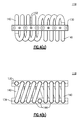
Figs. 4(a) and 4(b) are top plan and side views of an exemplary wire rope isolator for use in the seismic isolation assembly ofFigs. 2 and3 ; -
Figs. 5(a) and 5(b) are side views of an exemplary linear damper for use in the seismic isolation assembly ofFigs. 2-4 ; and -
Fig. 6 is a partial view of the ground supported structure ofFig. 1 , as supported by the seismic isolation assembly ofFigs. 2-5 . - The following relates to an exemplary embodiment of an assembly that is utilized to isolate seismic load inputs and in particular those inputs relative to an eccentric ground supported structure, such as the
circuit breaker 10 depicted inFig. 1 . It will be readily apparent to those of sufficient skill from the following description, however, that this assembly and variants thereof can easily be employed for effectively isolating other ground supported structures. In addition and in the course of discussion, certain terms such as horizontal", "vertical", "upper", "lower", "top", "bottom", "above", "below" and the like are used in order to provide a suitable frame of reference with regard to the accompanying drawings. These terms, however, are not intended to limit the scope of the inventive concepts, including the appended claims, unless such limitations are specifically indicated. - Referring to
Figs. 2 and3 , an exemplaryseismic isolation assembly 100 includes a first orlower support plate 104 and a second orupper support plate 110. Each of the lower andupper support plates Fig. 2 shows that thelower support plate 104 is attached, such through the use of bolts (not shown) secured throughopenings 105 extending through the thickness of thelower support plate 104 to a support structure on the ground. As more clearly seen inFig. 3 , aspacing 117 is defined between an upper surface orside 109 of thelower support plate 104 and a lower surface orside 111 of theupper support plate 110, as discussed herein. According to this embodiment, thelower support plate 104 is substantially rectangular in terms of configuration, with eachcorner 107 of thelower support plate 104 being beveled. Theupper support plate 110 is smaller in terms of its overall length and width dimensions than that of thelower support plate 104. For purposes of this exemplary embodiment, theupper support plate 110 is further defined by a substantially octagonal shape defined byrespective sides 115. It should be noted, however, that the herein described configuration is exemplary and other suitable polygonal shapes, including circular configurations, could be alternatively provided for either or both of the lower andupper support plates upper support plate 110 is substantially centered above thelower support plate 104, the support plates being disposed in a substantially horizontal configuration. A top orupper side 112 of theupper support plate 110 includes at least one set ofopenings 119 that are spaced and configured for fixedly and securely retaining an end of the structure to be isolated. - Still referring to
Figs. 2 and3 , a plurality ofwire rope isolators 118 are disposed within the definedspacing 117 between the lower andupper support plates wire rope isolator 118 is individually secured to thelower surface 111 of theupper support plate 110 and to the upper surface of a support block orplatform 127, the latter being bolted or otherwise fixedly mounted to theupper surface 109 of thelower support plate 104. Thesupport block 127 is exemplary and other mounting techniques to thelower support surface 104 or the base 113 can be utilized. According to this exemplary embodiment, a total of four (4)wire rope isolators 118 are disposed in equally spaced relation to one another between the lower andupper support plates - More specifically and referring to
Figs. 4(a) and 4(b) , eachwire rope isolator 118 according to this exemplary embodiment includes a rectangular shapedupper mounting block 130 and a parallel and correspondingly shapedlower mounting block 134, respectively. A plurality of cylindrical wire coils 140 are introduced between the mountingblocks block coils 140 are threaded therethrough and in which the ends of eachcoil 140 are attached to theupper mounting block 130. According to this embodiment, the mountingblocks blocks isolators 118, as well as the thickness of the cylindrical wire in thecoils 140 used can also be suitably varied, depending on the structure being supported and required spring rate, deflection and damping characteristics of a particular application. For example, one suitable wire rope isolator design which can be used for this purpose is described in commonly ownedU.S. Patent No. 5,449,285 to Collins , the entire contents of which are herein incorporated by reference. It will be readily apparent from the following discussion that other suitable isolator assemblies can be alternatively used. - Each of the mounting
blocks wire rope isolators 118 further includes a set of equally spaced transverse throughopenings 152 that are provided in opposing top and bottom sides thereof to permit attachment to thebottom surface 111 of theupper support plate 110 and the top surface of the supportingblock 127, respectively, using appropriately sized threaded fasteners. - As shown in
Figs. 2 and3 , the herein described isolation assembly further includes an additional plurality oflinear dampers 160 that are disposed between thelower support plate 104 and theupper support plate 110. Thesedampers 160 provide additional damping that cannot be provided by thewire rope isolators 118 due to loading conditions of the supportedstructure 10,Fig. 1 . - Referring to
Figs. 5(a) and 5(b) , each of thelinear dampers 160 according to this exemplary embodiment are defined by acylindrical housing 168 having afixed end 164 and an oppositely disposed axiallymovable end 166. The axiallymovable end 166 is further attached to apiston assembly 174 that includes apiston rod 176 extending within the interior of thecylindrical housing 168. The interior of thecylindrical housing 168 defines a damping chamber that is configured to retain a quantity of a hydraulic fluid and in which thepiston assembly 174 is configured to displace fluid within the cylinder and induce damping. Each of the movable and fixed ends 164, 166 of thecylinder 168 include fittings that enable transverse mounting. The stroke of thepiston assembly 174 can be selected based on the loading characteristics and structure to be supported and isolated. One example of a suitable hydraulic damper for these purposes is the LD damper series, manufactured by ITT Enidine, Inc., although other versions can be substituted. Alternatively, other forms of linear dampers such as linear friction dampers can also be substituted herein for the linear hydraulic dampers described herein. - According to this exemplary embodiment, four (4) sets of
linear dampers 160 are vertically disposed between the adjacently spacedwire rope isolators 118. Each of the four sets oflinear dampers 160 include a plurality of hydraulic viscous dampers in which eachfixed end 164 is independently secured to thelower support plate 104 and themovable end 166 is secured to an upwardly extending portion of amounting block 190, the latter being fixedly attached to thetop surface 112 of theupper support plate 110 and secured thereto using bolts or other suitable fasteners (not shown). Each of thelinear dampers 160 according to this particular embodiment are vertically disposed at an angle of approximately 68 degrees relative to theupper support plate 110. According to this exemplary embodiment, each set oflinear dampers 160 is defined by four (4) hydraulic dampers, which are disposed in side by side parallel relation to one another and independently mounted to thelower support plate 104 and mountingblock 190. The number of sets oflinear dampers 160 and the number of dampers in each set can be varied, as well as the vertical angle at which thelinear dampers 160 are disposed. As a result and due to their ease in accessibility and independent mounting, the number ofdampers 160 can be changed "on the fly" for purposes of testing and support/damping in actual use and in which thesupport block 127 and mounting plate can include a plurality of spaced attachment positions. - As previously noted, the stroke length of each
linear damper 160 can be suitably selected based on the loading characteristics, as well as the type of hydraulic fluid retained in thehousing 168 and the damping coefficient. - As shown in the figures and particularly
Fig. 6 and in terms of overall operation, the circuit breaker ofFig. 1 is again shown having a supportingvertical bracket 15 disposed at the lower or bottom end of thestructure 10 that is fixedly mounted to theupper side 112 of theupper support plate 110 while thelower support plate 104 is attached to ground. This supportedstructure 10 is isolated from seismic inputs from the ground, which is a multi-directional input. Based on the high and/or eccentric center of gravity of the supported structure a rocking component is created, which is non-axial. For purposes of tensile and compressive damping of the supported structure, thewire rope isolators 118 providing a low spring rate and some hysteretic damping in all directions. Thelinear dampers 160, being angularly mounted relative to the primary axis of the supportedstructure 10 are configured to provide additional damping to the system in all directions. That is, angular mounting of a plurality oflinear dampers 160 at the spaced locations enables additional damping as caused by seismic loads in all directions. The hydraulic damping is required because thewire rope isolators 118 fail to provide sufficient damping in all directions. - sIt will be readily apparent that other variations and modifications are possible utilizing the inventive concepts that are described herein and in accordance with the appended claims.
Claims (16)
- A seismic isolation assembly comprising:a first support plate configured for fixed attachment to a base;a second support plate disposed in parallel relation with the first support plate configured for fixed attachment to a structure including a spacing defined between the first and second support plates;a plurality of wire rope isolators fixedly mounted in spaced relation between the first support plate and the second support plate, each wire rope isolator being disposed along a major dimension of the support plates; anda plurality of linear dampers, each of the linear dampers being angularly mounted between the first and second support plates.
- A seismic isolation assembly as recited in claim 1, wherein a plurality of linear dampers are mounted in spaced relation between adjacent wire rope isolators.
- A seismic isolation assembly as recited in claim 2, wherein sets of wire rope isolators are disposed in spaced relation between the upper and lower support plates and in which at least two linear dampers are disposed in parallel relation between adjacent wire rope isolators.
- A seismic isolation assembly as recited in claim 1, wherein the linear dampers are mounted at an angle between about 45 and about 90 degrees relative to the major dimension of the second support plate.
- A seismic isolation assembly as recited in claim 1, wherein the linear dampers are hydraulic viscous dampers.
- A seismic isolation assembly as recited in claim 1, wherein the major dimension is horizontal.
- A seismic isolation assembly as recited in claim 3, wherein the linear dampers are independently mounted.
- A seismic isolation assembly as recited in claim 3, in which each set of linear dampers includes at least three (3) side by side linear dampers disposed at the angle relative to the major dimension of the support plates.
- A method for isolating a ground supported structure from seismic loads, said method comprising:providing a first support plate attached to ground;providing a second support plate in parallel relation to the first support plate, the second support plate being attached to the supported structure and in which a spacing is defined between the first and second support plates;mounting a set of isolators between the first and second support plates in a planar configuration, each of the isolators being wire rope isolators spaced from one another and disposed parallel to the planar configuration; andmounting a plurality of dampers to each of the first and second support plates at respective ends of each damper, the dampers being mounted at an angle relative to the planar configuration.
- A method as recited in claim 9, wherein the mounting angle of the dampers is between about 45 and 90 degrees relative to the planar configuration.
- A method as recited in claim 9, in which the dampers are linear dampers having a fixed end attached to ground and an axially movable end attached to the second support plate.
- A method as recited in claim 11, wherein the linear dampers are hydraulic viscous dampers.
- A method as recited in claim 9, in which at least one damper is disposed between adjacently mounted wire rope isolators.
- A method as recited in claim 11, in which a set of dampers is disposed between adjacent wire rope isolators, each set of dampers including at least one damper.
- A method as recited in claim 14, in which four wire rope isolators are disposed in spaced relation between the first and second support plates and in which each set of second isolators comprises at least one damper angularly disposed and in side by side in parallel relation between adjacent wire rope isolators.
- A method as recited in claim 14, in which each damper in a set is independently mounted.
Priority Applications (1)
| Application Number | Priority Date | Filing Date | Title |
|---|---|---|---|
| PL14194009T PL2889877T3 (en) | 2013-12-06 | 2014-11-20 | Seismic isolation assembly |
Applications Claiming Priority (1)
| Application Number | Priority Date | Filing Date | Title |
|---|---|---|---|
| US201361913035P | 2013-12-06 | 2013-12-06 |
Publications (2)
| Publication Number | Publication Date |
|---|---|
| EP2889877A1 true EP2889877A1 (en) | 2015-07-01 |
| EP2889877B1 EP2889877B1 (en) | 2021-03-10 |
Family
ID=51932249
Family Applications (1)
| Application Number | Title | Priority Date | Filing Date |
|---|---|---|---|
| EP14194009.8A Active EP2889877B1 (en) | 2013-12-06 | 2014-11-20 | Seismic isolation assembly |
Country Status (5)
| Country | Link |
|---|---|
| US (2) | US9255399B2 (en) |
| EP (1) | EP2889877B1 (en) |
| CL (1) | CL2014003245A1 (en) |
| ES (1) | ES2872931T3 (en) |
| PL (1) | PL2889877T3 (en) |
Cited By (2)
| Publication number | Priority date | Publication date | Assignee | Title |
|---|---|---|---|---|
| WO2016046104A1 (en) * | 2014-09-24 | 2016-03-31 | Siemens Aktiengesellschaft | Damping and support device for electrical equipments |
| EP2933815B1 (en) * | 2014-04-17 | 2019-01-16 | Terna Rete Italia S.p.A. | Seismic isolation device for a switch of the type used in high-voltage electric systems |
Families Citing this family (22)
| Publication number | Priority date | Publication date | Assignee | Title |
|---|---|---|---|---|
| CN103924705B (en) * | 2014-04-23 | 2015-06-10 | 华南理工大学建筑设计研究院 | Stiffness-variable seismic isolation layer stiffness control mechanism adaptive to structural seismic isolation and wind resistance |
| US20150345900A1 (en) * | 2014-05-28 | 2015-12-03 | Chief Of Naval Research, Office Of Counsel | Missile Launcher System |
| JP6614815B2 (en) * | 2014-06-16 | 2019-12-04 | ユニバーシティー プトラ マレーシア | Variable stiffness reinforcement |
| JP6787643B2 (en) * | 2015-08-21 | 2020-11-18 | Thk株式会社 | Upper and lower seismic isolation device |
| US10283837B2 (en) * | 2015-10-23 | 2019-05-07 | Viasat, Inc. | Apparatuses for mounting an antenna assembly |
| IT201600127545A1 (en) * | 2016-12-16 | 2018-06-16 | Nuovo Pignone Tecnologie Srl | Mounting system for rotating machines |
| CN106812866B (en) * | 2017-01-12 | 2018-10-02 | 中国航空工业集团公司北京航空材料研究院 | A kind of Three Degree Of Freedom irrotational displacement shock resistance platform |
| CN106815027B (en) * | 2017-01-22 | 2020-06-09 | 山东鲁能软件技术有限公司 | High-elasticity computing platform for power grid multi-dimensional service composite computing |
| US11002031B2 (en) | 2017-02-16 | 2021-05-11 | Koroneho Limited | Base isolation system |
| CN109211510A (en) * | 2017-07-06 | 2019-01-15 | 中国船舶重工集团公司第七〇四研究所 | A kind of measuring system shock resistance power supply platform |
| CN108839947A (en) * | 2018-05-11 | 2018-11-20 | 丁保明 | A kind of robot packing device of good damping effect |
| CN209082841U (en) * | 2018-09-12 | 2019-07-09 | 刘容彰 | Roof greening, radix saposhnikoviae suppression shake device and building |
| US11732495B2 (en) * | 2018-12-21 | 2023-08-22 | Esm Energie-Und Schwingungstechnik Mitsch Gmbh | Impulse tuned mass damper for tall, slim structures |
| CN109996417B (en) * | 2019-02-20 | 2023-10-20 | 和信精密科技(吴江)有限公司 | Detachable SERVER |
| CN110360411B (en) * | 2019-06-24 | 2021-02-26 | 江苏精工泵业有限公司 | Damping base for mixed flow pump |
| KR102262326B1 (en) * | 2020-01-01 | 2021-06-10 | 한국철도기술연구원 | Vibration-isolating system for cargo containers |
| JP7465702B2 (en) | 2020-03-30 | 2024-04-11 | 株式会社フジタ | Seismic isolation device and design method |
| US11313145B2 (en) * | 2020-09-15 | 2022-04-26 | Cal Poly Corporation | Earthquake protection systems, methods and apparatus using shape memory alloy (SMA)-based superelasticity-assisted slider (SSS) |
| CN112177415B (en) * | 2020-10-12 | 2022-08-05 | 同济大学 | TMD system that annular multi-direction was arranged |
| US20230036876A1 (en) * | 2020-11-27 | 2023-02-02 | Osaka University | Steel damper for seismic isolation and seismic isolation structure |
| CN112594326B (en) * | 2020-12-16 | 2022-08-12 | 河南铸盾人防工程安装有限公司 | Shock insulation system for combining large screen |
| CN115653380B (en) * | 2022-12-19 | 2023-03-10 | 中国电建集团山东电力建设第一工程有限公司 | Modular energy consumption assembly type structure for power transmission tower |
Citations (8)
| Publication number | Priority date | Publication date | Assignee | Title |
|---|---|---|---|---|
| US3794277A (en) * | 1972-08-14 | 1974-02-26 | A Smedley | Earthquake resistant support |
| US5449285A (en) | 1994-03-29 | 1995-09-12 | Davidson Textron, Inc. | Mold for molding a resin to form a complex article |
| US6098966A (en) * | 1999-04-19 | 2000-08-08 | Enidine Incorporated | Apparatus for absorbing shock and attenuating vibrations |
| US6530563B1 (en) * | 2001-07-10 | 2003-03-11 | Enidine, Incorporated | Multi-axis shock and vibration isolation system |
| DE102006054274B3 (en) * | 2006-11-17 | 2007-12-27 | Astrium Gmbh | Three-axis spring-damping system for platform in spacecraft for receiving of pay load over load pallet, has spring damping elements, which are arranged between retaining structure and load pallet |
| WO2012152826A1 (en) * | 2011-05-11 | 2012-11-15 | Dcns | Vessel of the type comprising at least one shaft for receiving at least one missile-launching container |
| JP2012246998A (en) * | 2011-05-27 | 2012-12-13 | Tanaka Seishin Kozo Kenkyusho:Kk | Vibration damping device |
| CN103410605A (en) * | 2013-08-20 | 2013-11-27 | 武汉海王科技有限公司 | 1E-level diesel generating set |
Family Cites Families (53)
| Publication number | Priority date | Publication date | Assignee | Title |
|---|---|---|---|---|
| US4108270A (en) | 1977-02-09 | 1978-08-22 | Exxon Production Research Company | Hydraulic stabilization system to position and isolate a seismic vibrator |
| US4858738A (en) * | 1978-07-26 | 1989-08-22 | Fernando Novoa | System of auxiliary mass dampers to restrain the response of slender elastic structures to vibrations such as from earthquakes |
| US4336917A (en) | 1979-10-11 | 1982-06-29 | Optimetrix Corporation | Shock and vibration isolation system |
| EP0103188B1 (en) | 1979-10-11 | 1986-12-03 | Eaton-Optimetrix Inc. | Improved shock and vibration isolation system |
| US5042024A (en) * | 1989-04-28 | 1991-08-20 | Pioneer Electronic Corporation | Disk reproduction apparatus capable of being disposed in different attitudes |
| JPH086493B2 (en) | 1991-05-29 | 1996-01-24 | 鹿島建設株式会社 | Vibration control device for structures |
| US5169110A (en) * | 1991-07-18 | 1992-12-08 | Aeroflex International Incorporated | Force-damping energy-removing isolator |
| US5360210A (en) | 1991-12-16 | 1994-11-01 | Vectra Technologies, Inc. | Pipe restraint |
| US5791636A (en) | 1992-07-16 | 1998-08-11 | Loziuk; Larry | Compact profile wire cable isolator and energy absorbing restraint |
| US5441243A (en) | 1992-07-16 | 1995-08-15 | Vectra Technologies, Inc. | Wire cable isolator and energy absorbing restraint |
| IT226869Z2 (en) | 1992-08-20 | 1997-07-22 | Camossi Carlo | METALLIC CABLE ELASTIC AND ANTI-VIBRATION DEVICE FOR THE SUPPORT OF A ROTATING GROUP |
| IT1262385B (en) * | 1993-08-03 | 1996-06-19 | Tis Tech Idraulico Stradali | MULTIDIRECTIONAL MECHANICAL ENERGY DISPERSER PARTICULARLY SUITABLE FOR THE BINDING OF STRUCTURES IN SEISMIC AREA. |
| US5559671A (en) | 1994-06-30 | 1996-09-24 | Hughes Aircraft Company | BI-directional shock isolation mounting system and method |
| US5549285A (en) | 1995-04-21 | 1996-08-27 | Enidine, Inc. | Wire rope isolator with crimp bar and method for making same |
| US5797227A (en) | 1996-04-09 | 1998-08-25 | Garza-Tamez; Federico | Structure stabilization system |
| DE29610411U1 (en) | 1996-06-13 | 1996-08-14 | Siemens Ag | Electronic device with mass storage |
| IT1294130B1 (en) | 1997-05-15 | 1999-03-22 | Electrolux Zanussi Elettrodome | METHOD TO REALIZE AN ACTIVE DAMPING OF VIBRATIONS DUE TO THE WASHING GROUP AND WASHING MACHINE TO IMPLEMENT THIS |
| US6286805B1 (en) | 1998-07-01 | 2001-09-11 | Clear Vision Laser Centers, Inc. | Apparatus and method for transporting equipment between buildings |
| DE19859897C1 (en) | 1998-12-23 | 2000-08-10 | Knorr Bremse Systeme | Device for vibration-damping mounting of a compressed air generation system on a mounting bracket of a rail vehicle |
| US6244579B1 (en) | 2000-02-02 | 2001-06-12 | Enidine, Incorporated | Light press manufactured (LPM) wire rope isolator and method of manufacture |
| US6406011B1 (en) | 2000-02-02 | 2002-06-18 | Enidine Incorporated | Wire rope isolator with pinned bar and method for making same |
| US6290217B1 (en) | 2000-03-29 | 2001-09-18 | Enidine Incorporated | Asymmetric wire rope isolator |
| US20030016996A1 (en) | 2001-07-23 | 2003-01-23 | Gelfand Matthew A. | Energy absorbing system |
| US20030132077A1 (en) * | 2002-01-15 | 2003-07-17 | Davis Toren S. | Tuned mass damper using a hexapod |
| NZ535115A (en) | 2002-02-07 | 2007-11-30 | Universal Safety Response Inc | Energy absorbing system |
| NL1022035C2 (en) * | 2002-11-29 | 2004-06-07 | Thales Nederland Bv | Elemental and complex coupling devices, and their uses. |
| US7070177B2 (en) * | 2003-02-18 | 2006-07-04 | Arvinmeritor Technology, Llc | Sandwich design of four bag suspension for bus and coach rear drive axles |
| US7337586B2 (en) | 2004-06-14 | 2008-03-04 | Chi-Chang Lin | Anti-seismic device with vibration-reducing units arranged in parallel |
| WO2006002027A2 (en) | 2004-06-15 | 2006-01-05 | Griffin Analytical Technologies, Inc. | Portable mass spectrometer configured to perform multidimensional mass analysis |
| IL164229A (en) * | 2004-09-22 | 2010-05-17 | Rafael Advanced Defense Sys | Vibration damping pylon |
| US7108111B2 (en) | 2004-10-25 | 2006-09-19 | Enidine Incorporated | Semi-active isolator |
| US20060201759A1 (en) | 2005-03-11 | 2006-09-14 | Enidine, Inc. | Isolation cabinet |
| US7325792B2 (en) | 2005-03-11 | 2008-02-05 | Enidine, Inc. | Multi-axial base isolation system |
| US7487958B2 (en) * | 2005-05-10 | 2009-02-10 | Shu-Lung Wang | Anti-vibration mechanism for dental impression material mixer |
| JP2007039894A (en) | 2005-08-01 | 2007-02-15 | Shimizu Corp | Shock-absorbing and holding device for scaffold |
| US7852274B2 (en) | 2005-12-16 | 2010-12-14 | Rockwell Collins Satellite Communications Systems, Inc. | Communications trailer |
| WO2008022466A1 (en) | 2006-08-25 | 2008-02-28 | March Networks Corporation | Mobile event data recorder with multiple orientation vibration isolation |
| US7837380B2 (en) * | 2006-12-26 | 2010-11-23 | Shu-Lung Wang | Guarding structure for a mixer of molding material |
| US8246020B2 (en) * | 2007-03-23 | 2012-08-21 | Komatsu Ltd. | Damping device |
| NO330721B1 (en) | 2008-03-11 | 2011-06-20 | Techni As | Damping means |
| US8444121B2 (en) | 2008-03-31 | 2013-05-21 | Honeywell International Inc. | Systems for damping vibrations from a payload |
| DE102008017926B3 (en) * | 2008-04-08 | 2009-05-14 | Rheinmetall Waffe Munition Gmbh | Stabilizing device for stabilizing launcher during firing of e.g. decoy, has pretensioning device exerting pressure on curved bar over pressure and catch pieces, so that movable system is released upon exceedence of given value of damper |
| CN102318137B (en) | 2008-12-15 | 2014-03-12 | 西泰尔股份有限公司 | Pedestal for tracking antenna |
| CN101882460B (en) | 2009-05-08 | 2012-07-04 | 中国船舶重工集团公司第七0四研究所 | Steel wire rope type computer hard disk vibration isolator |
| US8235351B1 (en) | 2009-08-27 | 2012-08-07 | Lockheed Martin Corporation | Shock load isolation mounting |
| MX2012003202A (en) * | 2009-09-25 | 2012-05-29 | Vsl Int Ag | Method and structure for damping movement in buildings. |
| ES2401365T3 (en) | 2009-11-20 | 2013-04-19 | Eads Deutschland Gmbh | Shock Insulation Structure |
| ES2404879T3 (en) | 2010-06-02 | 2013-05-29 | Thales Nederland B.V. | Device to isolate an object from external movements |
| US8919714B2 (en) | 2010-10-13 | 2014-12-30 | Re2, Inc. | Compliant tool holder |
| US8480052B2 (en) * | 2011-01-11 | 2013-07-09 | Drs Tactical Systems, Inc. | Vibration isolating device |
| CN201971165U (en) | 2011-03-28 | 2011-09-14 | 广州市红鹏直升机遥感科技有限公司 | Vibration damper of holder for aerial photographing |
| US9127744B2 (en) * | 2012-07-05 | 2015-09-08 | Chapman/Leonard Studio Equipment, Inc. | Camera isolator with adjustable dampening |
| US20140305334A1 (en) * | 2013-04-12 | 2014-10-16 | Electro-Motive Diesel, Inc. | Mounting structure for driving unit and driven unit of locomotive |
-
2014
- 2014-11-20 PL PL14194009T patent/PL2889877T3/en unknown
- 2014-11-20 ES ES14194009T patent/ES2872931T3/en active Active
- 2014-11-20 EP EP14194009.8A patent/EP2889877B1/en active Active
- 2014-11-28 CL CL2014003245A patent/CL2014003245A1/en unknown
- 2014-12-04 US US14/560,817 patent/US9255399B2/en active Active
-
2016
- 2016-01-14 US US14/995,314 patent/US9809975B2/en active Active
Patent Citations (8)
| Publication number | Priority date | Publication date | Assignee | Title |
|---|---|---|---|---|
| US3794277A (en) * | 1972-08-14 | 1974-02-26 | A Smedley | Earthquake resistant support |
| US5449285A (en) | 1994-03-29 | 1995-09-12 | Davidson Textron, Inc. | Mold for molding a resin to form a complex article |
| US6098966A (en) * | 1999-04-19 | 2000-08-08 | Enidine Incorporated | Apparatus for absorbing shock and attenuating vibrations |
| US6530563B1 (en) * | 2001-07-10 | 2003-03-11 | Enidine, Incorporated | Multi-axis shock and vibration isolation system |
| DE102006054274B3 (en) * | 2006-11-17 | 2007-12-27 | Astrium Gmbh | Three-axis spring-damping system for platform in spacecraft for receiving of pay load over load pallet, has spring damping elements, which are arranged between retaining structure and load pallet |
| WO2012152826A1 (en) * | 2011-05-11 | 2012-11-15 | Dcns | Vessel of the type comprising at least one shaft for receiving at least one missile-launching container |
| JP2012246998A (en) * | 2011-05-27 | 2012-12-13 | Tanaka Seishin Kozo Kenkyusho:Kk | Vibration damping device |
| CN103410605A (en) * | 2013-08-20 | 2013-11-27 | 武汉海王科技有限公司 | 1E-level diesel generating set |
Cited By (3)
| Publication number | Priority date | Publication date | Assignee | Title |
|---|---|---|---|---|
| EP2933815B1 (en) * | 2014-04-17 | 2019-01-16 | Terna Rete Italia S.p.A. | Seismic isolation device for a switch of the type used in high-voltage electric systems |
| WO2016046104A1 (en) * | 2014-09-24 | 2016-03-31 | Siemens Aktiengesellschaft | Damping and support device for electrical equipments |
| US10539204B2 (en) | 2014-09-24 | 2020-01-21 | Itt Manufacturing Enterprises Llc | Damping and support device for electrical equipments |
Also Published As
| Publication number | Publication date |
|---|---|
| US9809975B2 (en) | 2017-11-07 |
| EP2889877B1 (en) | 2021-03-10 |
| US20150159370A1 (en) | 2015-06-11 |
| PL2889877T3 (en) | 2021-09-20 |
| US20160130805A1 (en) | 2016-05-12 |
| NZ702029A (en) | 2018-03-23 |
| ES2872931T3 (en) | 2021-11-03 |
| US9255399B2 (en) | 2016-02-09 |
| CL2014003245A1 (en) | 2015-11-20 |
Similar Documents
| Publication | Publication Date | Title |
|---|---|---|
| US9809975B2 (en) | Seismic isolation assembly | |
| US10539204B2 (en) | Damping and support device for electrical equipments | |
| US20060202398A1 (en) | Multi-axial base isolation system | |
| CN203096936U (en) | Tensile vibration-isolation support provided with steel wire ropes | |
| KR101802323B1 (en) | Bearing | |
| KR101701810B1 (en) | Seismic equipment | |
| TR201507393A2 (en) | A variable stiffness bracing device | |
| CN104674973A (en) | Shock isolation device with tensile property | |
| WO2019027349A1 (en) | Vibration isolation platform for high-sensitivity equipment and vibration sources | |
| CN102706748A (en) | Method and device capable of increasing effective working space of tensile testing machine | |
| CN104376972A (en) | 500kV transformer shock insulation structure and installation method | |
| EP2933815B1 (en) | Seismic isolation device for a switch of the type used in high-voltage electric systems | |
| NZ702029B (en) | Seismic isolation assembly | |
| EP2202367B1 (en) | Device for positioning floating concrete slabs | |
| RU2537984C1 (en) | Kochetov's disk-shaped vibration isolator with dry friction damper | |
| CN112681862A (en) | Shock isolation device for power transmission tower base and mounting method thereof | |
| US7090207B2 (en) | Single-end-mount seismic isolator | |
| RU2516967C2 (en) | Vibration absorber of quasi-zero stiffness | |
| RU2538489C1 (en) | Kochetov's equifrequential package of disk-type elastic elements | |
| KR102249905B1 (en) | Vibration isloation apparatus | |
| US3746292A (en) | Vessell stabilization system | |
| RU2550914C1 (en) | Beaded mesh vibration isolator by kochetov | |
| CN108824664B (en) | Embedded composite shock insulation device, embedded composite shock insulation system and use method thereof | |
| CN211778702U (en) | Elastic vibration damping pad | |
| Prost et al. | Wire rope isolators for seismic base isolation |
Legal Events
| Date | Code | Title | Description |
|---|---|---|---|
| PUAI | Public reference made under article 153(3) epc to a published international application that has entered the european phase |
Free format text: ORIGINAL CODE: 0009012 |
|
| 17P | Request for examination filed |
Effective date: 20141120 |
|
| AK | Designated contracting states |
Kind code of ref document: A1 Designated state(s): AL AT BE BG CH CY CZ DE DK EE ES FI FR GB GR HR HU IE IS IT LI LT LU LV MC MK MT NL NO PL PT RO RS SE SI SK SM TR |
|
| AX | Request for extension of the european patent |
Extension state: BA ME |
|
| R17P | Request for examination filed (corrected) |
Effective date: 20160104 |
|
| RBV | Designated contracting states (corrected) |
Designated state(s): AL AT BE BG CH CY CZ DE DK EE ES FI FR GB GR HR HU IE IS IT LI LT LU LV MC MK MT NL NO PL PT RO RS SE SI SK SM TR |
|
| STAA | Information on the status of an ep patent application or granted ep patent |
Free format text: STATUS: EXAMINATION IS IN PROGRESS |
|
| 17Q | First examination report despatched |
Effective date: 20190711 |
|
| REG | Reference to a national code |
Ref country code: DE Ref legal event code: R079 Ref document number: 602014075515 Country of ref document: DE Free format text: PREVIOUS MAIN CLASS: G10K0011160000 Ipc: E02D0027340000 |
|
| GRAP | Despatch of communication of intention to grant a patent |
Free format text: ORIGINAL CODE: EPIDOSNIGR1 |
|
| STAA | Information on the status of an ep patent application or granted ep patent |
Free format text: STATUS: GRANT OF PATENT IS INTENDED |
|
| RIC1 | Information provided on ipc code assigned before grant |
Ipc: F16F 7/14 20060101ALI20201103BHEP Ipc: F16F 15/02 20060101ALI20201103BHEP Ipc: E02D 27/34 20060101AFI20201103BHEP Ipc: G10K 11/16 20060101ALI20201103BHEP |
|
| INTG | Intention to grant announced |
Effective date: 20201204 |
|
| STAA | Information on the status of an ep patent application or granted ep patent |
Free format text: STATUS: GRANT OF PATENT IS INTENDED |
|
| GRAS | Grant fee paid |
Free format text: ORIGINAL CODE: EPIDOSNIGR3 |
|
| GRAA | (expected) grant |
Free format text: ORIGINAL CODE: 0009210 |
|
| STAA | Information on the status of an ep patent application or granted ep patent |
Free format text: STATUS: THE PATENT HAS BEEN GRANTED |
|
| AK | Designated contracting states |
Kind code of ref document: B1 Designated state(s): AL AT BE BG CH CY CZ DE DK EE ES FI FR GB GR HR HU IE IS IT LI LT LU LV MC MK MT NL NO PL PT RO RS SE SI SK SM TR |
|
| REG | Reference to a national code |
Ref country code: GB Ref legal event code: FG4D |
|
| REG | Reference to a national code |
Ref country code: AT Ref legal event code: REF Ref document number: 1369933 Country of ref document: AT Kind code of ref document: T Effective date: 20210315 Ref country code: CH Ref legal event code: EP |
|
| REG | Reference to a national code |
Ref country code: DE Ref legal event code: R096 Ref document number: 602014075515 Country of ref document: DE |
|
| REG | Reference to a national code |
Ref country code: IE Ref legal event code: FG4D |
|
| REG | Reference to a national code |
Ref country code: NL Ref legal event code: FP |
|
| REG | Reference to a national code |
Ref country code: LT Ref legal event code: MG9D |
|
| PG25 | Lapsed in a contracting state [announced via postgrant information from national office to epo] |
Ref country code: NO Free format text: LAPSE BECAUSE OF FAILURE TO SUBMIT A TRANSLATION OF THE DESCRIPTION OR TO PAY THE FEE WITHIN THE PRESCRIBED TIME-LIMIT Effective date: 20210610 Ref country code: BG Free format text: LAPSE BECAUSE OF FAILURE TO SUBMIT A TRANSLATION OF THE DESCRIPTION OR TO PAY THE FEE WITHIN THE PRESCRIBED TIME-LIMIT Effective date: 20210610 Ref country code: GR Free format text: LAPSE BECAUSE OF FAILURE TO SUBMIT A TRANSLATION OF THE DESCRIPTION OR TO PAY THE FEE WITHIN THE PRESCRIBED TIME-LIMIT Effective date: 20210611 Ref country code: HR Free format text: LAPSE BECAUSE OF FAILURE TO SUBMIT A TRANSLATION OF THE DESCRIPTION OR TO PAY THE FEE WITHIN THE PRESCRIBED TIME-LIMIT Effective date: 20210310 Ref country code: FI Free format text: LAPSE BECAUSE OF FAILURE TO SUBMIT A TRANSLATION OF THE DESCRIPTION OR TO PAY THE FEE WITHIN THE PRESCRIBED TIME-LIMIT Effective date: 20210310 Ref country code: LT Free format text: LAPSE BECAUSE OF FAILURE TO SUBMIT A TRANSLATION OF THE DESCRIPTION OR TO PAY THE FEE WITHIN THE PRESCRIBED TIME-LIMIT Effective date: 20210310 |
|
| REG | Reference to a national code |
Ref country code: AT Ref legal event code: MK05 Ref document number: 1369933 Country of ref document: AT Kind code of ref document: T Effective date: 20210310 |
|
| PG25 | Lapsed in a contracting state [announced via postgrant information from national office to epo] |
Ref country code: SE Free format text: LAPSE BECAUSE OF FAILURE TO SUBMIT A TRANSLATION OF THE DESCRIPTION OR TO PAY THE FEE WITHIN THE PRESCRIBED TIME-LIMIT Effective date: 20210310 Ref country code: RS Free format text: LAPSE BECAUSE OF FAILURE TO SUBMIT A TRANSLATION OF THE DESCRIPTION OR TO PAY THE FEE WITHIN THE PRESCRIBED TIME-LIMIT Effective date: 20210310 Ref country code: LV Free format text: LAPSE BECAUSE OF FAILURE TO SUBMIT A TRANSLATION OF THE DESCRIPTION OR TO PAY THE FEE WITHIN THE PRESCRIBED TIME-LIMIT Effective date: 20210310 |
|
| PG25 | Lapsed in a contracting state [announced via postgrant information from national office to epo] |
Ref country code: CZ Free format text: LAPSE BECAUSE OF FAILURE TO SUBMIT A TRANSLATION OF THE DESCRIPTION OR TO PAY THE FEE WITHIN THE PRESCRIBED TIME-LIMIT Effective date: 20210310 Ref country code: EE Free format text: LAPSE BECAUSE OF FAILURE TO SUBMIT A TRANSLATION OF THE DESCRIPTION OR TO PAY THE FEE WITHIN THE PRESCRIBED TIME-LIMIT Effective date: 20210310 Ref country code: AT Free format text: LAPSE BECAUSE OF FAILURE TO SUBMIT A TRANSLATION OF THE DESCRIPTION OR TO PAY THE FEE WITHIN THE PRESCRIBED TIME-LIMIT Effective date: 20210310 Ref country code: SM Free format text: LAPSE BECAUSE OF FAILURE TO SUBMIT A TRANSLATION OF THE DESCRIPTION OR TO PAY THE FEE WITHIN THE PRESCRIBED TIME-LIMIT Effective date: 20210310 |
|
| REG | Reference to a national code |
Ref country code: ES Ref legal event code: FG2A Ref document number: 2872931 Country of ref document: ES Kind code of ref document: T3 Effective date: 20211103 |
|
| PG25 | Lapsed in a contracting state [announced via postgrant information from national office to epo] |
Ref country code: IS Free format text: LAPSE BECAUSE OF FAILURE TO SUBMIT A TRANSLATION OF THE DESCRIPTION OR TO PAY THE FEE WITHIN THE PRESCRIBED TIME-LIMIT Effective date: 20210710 Ref country code: SK Free format text: LAPSE BECAUSE OF FAILURE TO SUBMIT A TRANSLATION OF THE DESCRIPTION OR TO PAY THE FEE WITHIN THE PRESCRIBED TIME-LIMIT Effective date: 20210310 Ref country code: RO Free format text: LAPSE BECAUSE OF FAILURE TO SUBMIT A TRANSLATION OF THE DESCRIPTION OR TO PAY THE FEE WITHIN THE PRESCRIBED TIME-LIMIT Effective date: 20210310 Ref country code: PT Free format text: LAPSE BECAUSE OF FAILURE TO SUBMIT A TRANSLATION OF THE DESCRIPTION OR TO PAY THE FEE WITHIN THE PRESCRIBED TIME-LIMIT Effective date: 20210712 |
|
| REG | Reference to a national code |
Ref country code: DE Ref legal event code: R097 Ref document number: 602014075515 Country of ref document: DE |
|
| PLBE | No opposition filed within time limit |
Free format text: ORIGINAL CODE: 0009261 |
|
| STAA | Information on the status of an ep patent application or granted ep patent |
Free format text: STATUS: NO OPPOSITION FILED WITHIN TIME LIMIT |
|
| PG25 | Lapsed in a contracting state [announced via postgrant information from national office to epo] |
Ref country code: DK Free format text: LAPSE BECAUSE OF FAILURE TO SUBMIT A TRANSLATION OF THE DESCRIPTION OR TO PAY THE FEE WITHIN THE PRESCRIBED TIME-LIMIT Effective date: 20210310 Ref country code: AL Free format text: LAPSE BECAUSE OF FAILURE TO SUBMIT A TRANSLATION OF THE DESCRIPTION OR TO PAY THE FEE WITHIN THE PRESCRIBED TIME-LIMIT Effective date: 20210310 |
|
| 26N | No opposition filed |
Effective date: 20211213 |
|
| PG25 | Lapsed in a contracting state [announced via postgrant information from national office to epo] |
Ref country code: SI Free format text: LAPSE BECAUSE OF FAILURE TO SUBMIT A TRANSLATION OF THE DESCRIPTION OR TO PAY THE FEE WITHIN THE PRESCRIBED TIME-LIMIT Effective date: 20210310 |
|
| PG25 | Lapsed in a contracting state [announced via postgrant information from national office to epo] |
Ref country code: IS Free format text: LAPSE BECAUSE OF FAILURE TO SUBMIT A TRANSLATION OF THE DESCRIPTION OR TO PAY THE FEE WITHIN THE PRESCRIBED TIME-LIMIT Effective date: 20210710 |
|
| PG25 | Lapsed in a contracting state [announced via postgrant information from national office to epo] |
Ref country code: MC Free format text: LAPSE BECAUSE OF FAILURE TO SUBMIT A TRANSLATION OF THE DESCRIPTION OR TO PAY THE FEE WITHIN THE PRESCRIBED TIME-LIMIT Effective date: 20210310 |
|
| REG | Reference to a national code |
Ref country code: CH Ref legal event code: PL |
|
| REG | Reference to a national code |
Ref country code: NL Ref legal event code: MM Effective date: 20211201 |
|
| PG25 | Lapsed in a contracting state [announced via postgrant information from national office to epo] |
Ref country code: LU Free format text: LAPSE BECAUSE OF NON-PAYMENT OF DUE FEES Effective date: 20211120 Ref country code: BE Free format text: LAPSE BECAUSE OF NON-PAYMENT OF DUE FEES Effective date: 20211130 |
|
| REG | Reference to a national code |
Ref country code: BE Ref legal event code: MM Effective date: 20211130 |
|
| PG25 | Lapsed in a contracting state [announced via postgrant information from national office to epo] |
Ref country code: LI Free format text: LAPSE BECAUSE OF NON-PAYMENT OF DUE FEES Effective date: 20211130 Ref country code: CH Free format text: LAPSE BECAUSE OF NON-PAYMENT OF DUE FEES Effective date: 20211130 |
|
| PG25 | Lapsed in a contracting state [announced via postgrant information from national office to epo] |
Ref country code: NL Free format text: LAPSE BECAUSE OF NON-PAYMENT OF DUE FEES Effective date: 20211201 |
|
| PG25 | Lapsed in a contracting state [announced via postgrant information from national office to epo] |
Ref country code: IE Free format text: LAPSE BECAUSE OF NON-PAYMENT OF DUE FEES Effective date: 20211120 |
|
| PGFP | Annual fee paid to national office [announced via postgrant information from national office to epo] |
Ref country code: PL Payment date: 20221025 Year of fee payment: 9 |
|
| PG25 | Lapsed in a contracting state [announced via postgrant information from national office to epo] |
Ref country code: HU Free format text: LAPSE BECAUSE OF FAILURE TO SUBMIT A TRANSLATION OF THE DESCRIPTION OR TO PAY THE FEE WITHIN THE PRESCRIBED TIME-LIMIT; INVALID AB INITIO Effective date: 20141120 |
|
| PG25 | Lapsed in a contracting state [announced via postgrant information from national office to epo] |
Ref country code: CY Free format text: LAPSE BECAUSE OF FAILURE TO SUBMIT A TRANSLATION OF THE DESCRIPTION OR TO PAY THE FEE WITHIN THE PRESCRIBED TIME-LIMIT Effective date: 20210310 |
|
| P01 | Opt-out of the competence of the unified patent court (upc) registered |
Effective date: 20230528 |
|
| PGFP | Annual fee paid to national office [announced via postgrant information from national office to epo] |
Ref country code: GB Payment date: 20231019 Year of fee payment: 10 |
|
| PGFP | Annual fee paid to national office [announced via postgrant information from national office to epo] |
Ref country code: ES Payment date: 20231201 Year of fee payment: 10 |
|
| PGFP | Annual fee paid to national office [announced via postgrant information from national office to epo] |
Ref country code: IT Payment date: 20231019 Year of fee payment: 10 Ref country code: FR Payment date: 20231019 Year of fee payment: 10 Ref country code: DE Payment date: 20231019 Year of fee payment: 10 |
|
| PGFP | Annual fee paid to national office [announced via postgrant information from national office to epo] |
Ref country code: PL Payment date: 20231020 Year of fee payment: 10 |