US3746292A - Vessell stabilization system - Google Patents
Vessell stabilization system Download PDFInfo
- Publication number
- US3746292A US3746292A US00147871A US3746292DA US3746292A US 3746292 A US3746292 A US 3746292A US 00147871 A US00147871 A US 00147871A US 3746292D A US3746292D A US 3746292DA US 3746292 A US3746292 A US 3746292A
- Authority
- US
- United States
- Prior art keywords
- vessel
- cross members
- yoke
- bars
- lug
- Prior art date
- Legal status (The legal status is an assumption and is not a legal conclusion. Google has not performed a legal analysis and makes no representation as to the accuracy of the status listed.)
- Expired - Lifetime
Links
- 230000006641 stabilisation Effects 0.000 title description 6
- 238000011105 stabilization Methods 0.000 title description 6
- 230000000087 stabilizing effect Effects 0.000 claims abstract description 4
- 239000003381 stabilizer Substances 0.000 claims description 13
- 230000000712 assembly Effects 0.000 claims description 2
- 238000000429 assembly Methods 0.000 claims description 2
- 238000009434 installation Methods 0.000 description 4
- 230000036316 preload Effects 0.000 description 4
- 229910000831 Steel Inorganic materials 0.000 description 2
- 230000008602 contraction Effects 0.000 description 2
- NJPPVKZQTLUDBO-UHFFFAOYSA-N novaluron Chemical compound C1=C(Cl)C(OC(F)(F)C(OC(F)(F)F)F)=CC=C1NC(=O)NC(=O)C1=C(F)C=CC=C1F NJPPVKZQTLUDBO-UHFFFAOYSA-N 0.000 description 2
- 125000006850 spacer group Chemical group 0.000 description 2
- 239000010959 steel Substances 0.000 description 2
- 238000003466 welding Methods 0.000 description 2
- 238000010276 construction Methods 0.000 description 1
- 239000000446 fuel Substances 0.000 description 1
- 238000004519 manufacturing process Methods 0.000 description 1
- 238000000034 method Methods 0.000 description 1
Images
Classifications
-
- G—PHYSICS
- G21—NUCLEAR PHYSICS; NUCLEAR ENGINEERING
- G21C—NUCLEAR REACTORS
- G21C13/00—Pressure vessels; Containment vessels; Containment in general
- G21C13/02—Details
- G21C13/024—Supporting constructions for pressure vessels or containment vessels
-
- Y—GENERAL TAGGING OF NEW TECHNOLOGICAL DEVELOPMENTS; GENERAL TAGGING OF CROSS-SECTIONAL TECHNOLOGIES SPANNING OVER SEVERAL SECTIONS OF THE IPC; TECHNICAL SUBJECTS COVERED BY FORMER USPC CROSS-REFERENCE ART COLLECTIONS [XRACs] AND DIGESTS
- Y02—TECHNOLOGIES OR APPLICATIONS FOR MITIGATION OR ADAPTATION AGAINST CLIMATE CHANGE
- Y02E—REDUCTION OF GREENHOUSE GAS [GHG] EMISSIONS, RELATED TO ENERGY GENERATION, TRANSMISSION OR DISTRIBUTION
- Y02E30/00—Energy generation of nuclear origin
- Y02E30/30—Nuclear fission reactors
Definitions
- a pressure vessel is typically used to house the fuel core and other components of a nuclear power reactor.
- a pressure vessel may be 6070 feet high, in the order of feet in diameter and contain a pressure of 1,000 pounds per square inch, the vessel being supported by a pedestal or support shroud attached near the bottom of the vessel.
- Such an elongated vessel generally requres some type of lateral stabilization against earthquake and similar forces.
- the vessel In a known reactor pressure vessel installation, the vessel is surrounded by a concrete shield wall spaced from the vessel and extending short of the top of the vessel.
- a plurality of radially extending lugs are welded to the vessel just above the shield wall. The outer ends of each of these lugs is formed with a horizontal clearance hole to receive a rod and each end of this rod engages a bracket secured to the shield wall.
- Heavy disc springs mounted on the rods and prestressed between the lugs and the brackets provide lateral stabilization of the pressure vessel. This arrangement is found to present several shortcomings. If the lugs are formed with holes in the factory, then installation of the lugs on the pressure vessel must be quite precise.
- a stabilizer assembly formed of a yoke for engaging the lugs on the pressure vessel.
- the yoke is tapped to receive oppositely extending threaded rods or bars which pass through clearance holes in a bracket secured to the shield wall or other fixed structure surrounding the vessel.
- Disc springs are mounted on these rods and are prestressed between the bracket and nuts threaded on the ends of the rods to provide the snubbing force requisite to vessel stabilization.
- the yoke can be sized to accommodate thermally induced movement of the vessel; the assembly can be factory assembled including prestressing of the springs; and the yoke opening inexpensively can be adjusted in the field for appropriate clearance from the vessel lug by simply installed shims.
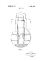
- FIG. 1 is an elevation view of a pressure vessel within a containment
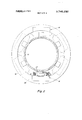
- FIG. 2 is a cross section view of the structure of FIG. 1 taken along the line 2-2 of FIG. 1;
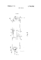
- FIG. 3 is a horizontal view of the assembly of the invention.
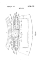
- FIG. 4 is a top detail view, partly in section, of a stabilizer assembly of FIG. 3 taken along the line 44 of FIG. 3.
- FIG. 1 Shown in FIG. 1 is a cylindrical pressure vessel 10, housed within a dry well 11 of a containment 12.
- the vessel 10 is supported by a shroud 13 where it bears upon a support pedestal 14 of the containment structure.
- the vessel 10 is surrounded by a cylindrical shield wall 16, usually formed of concentric steel cylinders filled with concrete.
- the vessel stabilizing arrangement comprises a plurality of lugs 17 fixed (as by welding) to the vessel 10 and projecting radially therefrom just above the top of the shield wall 16.
- Each lug 17 is engaged by a respective one of a plurality of stabilizer assemblies 18 mounted on the shield wall 16.
- a stabilizer assembly 18 is shown in greater detail in FIGS. 3 and 4.
- Each stabilizer assembly 18 includes a yoke 19 having a central opening 21 sized to receive the lug 17 with appropriate clearance.
- the opening 21 may be formed oversized in width to accommodate construction tolerances. Shims 22 may then be field installed to provide the desired clearance between the yoke 19 and the lug
- the yoke 19 is positioned with clearance within a bracket 23 formed of a base plate 24, side members 26(1) and 26(2) and cross members 27(1) and 27(2).
- the side members 26(1) and 26(2) are formed with cut outs to clear the lug 17 and to provide access to the opening 21 in yoke 19.
- the yoke 19 is drilled and tapped at opposite sides to receive a pair of oppositely extending threaded rods or bars 29(1) and 29(2) which pass through clearance holes in bracket cross members 27(1) and 27(2), respectively.
- rods 29(1) and 29(2) are mounted, respectively, the following: washers 31(1) and 31(2), disc spring sets 32(1) and 32(2), spacers 33(1) and 33(2), sleeves 34(1) and 34(2), washers 36(1) and 36(2) and nuts 37(1) and 37(2).
- the shield wall 16 is ordinarily fitted with a steel to ring 38.
- the bracket 23 may be secured to this ring, for example, by bolts, cap screws or the like or by welding as illustrated.
- the stabilizer assembly 18 is well adapted for factory assembly and preload.
- a factory assembly procedure is as follows: the yoke 19 is positioned in the bracket 23. Rods 29(1) and 29(2) are threaded into yoke 19 and are preferably tack welded to prevent disengagement. Washers 31(1) and 31(2), disc spring sets 32(1) and 32(2), spacers 33(1) and 33(2), sleeves 34(1) and 34(2), washers 36(1) and 36(2) and nuts 37(1) and 37(2) are placed on the rods 29(1) and 29(2). Opposing forces are then applied, preferably to the sleeves 34(1) and 34(2) by a suitable tensioner device (not shown) to precompress the spring sets 32(1) and 32(2) to the desired preload. The nuts 37(1) and 37(2) are run up against the sleeves 34(1) and 34(2) to maintain this preload and the tensioner device then may be removed. The stabilizer assembly 18 is now ready for field installation.
- a field installation procedure is as follows: the stabilizer assembly 18 is placed on top of the shield wall 16 and is moved toward the pressure vessel so that the lug 17 is inserted into the opening 21 of the yoke 19. The assembly 18 is positioned so that the sides of the lug 17 and the sides of the opening 19 are as nearly parallel as feasible and so that the gaps between the lug 17 and opening 19 are substantially equal. The assembly 18 is then clamped in place and welded to the ring 38 or otherwise secured to the shield wall 16. Shims 22 are now installed to provide a predetermined clearance C between the yoke 19 and lug 17 when the pressure vessel is in the hot condition.
- the shims 22 may be welded in place or, conveniently, they may be formed with a flange 39 by which they may be secured to the lug 17 with cap screws 41.
- the shims 22 may be machined with a taper if required to compensate for any lack of parallelism between the lug 17 and the sides of the opening 21 of the yoke 19.
- the lug 17 is toward the top of the opening 21, typical of its position when the pressure vessel 10 is in the hot condition.
- the pressure vessel When the pressure vessel is in the cold condition it is contracted so that the lug 17 is toward the bottom of the opening 21.
- the height of the opening 21 is selected to accommodate this change of position of the lug 17 with temperature.
- the following table sets forth the principal dimensions and parameters of the elements of a stabilizer assembly arrangement for use with the pressure vessel of a typical nuclear power reactor of about 65 feet in height, about 20 feet in diameter and with a loaded weight of about 600 tons.
- bers having a central opening surrounding said respective one of said lugs, a pair of bars secured to said yoke and extending oppositely therefrom through clearance holes in said cross members, and resilient means carried by said bars, said resilient means being precompressed between the outer ends of said bars and said cross members.
- a stabilizer assembly for engaging 3. lug on a vessel comprising: a bracket including a relatively rigidly fixed base, a pair of spaced side members fixed to said base and formed with cut outs to pass said lug, a pair of spaced cross members secured between said side members; a yoke positioned between said cross members, said yoke being formed with a central opening to engage said lug; a pair of oppositely extending bars secured to said yoke and extending through clearance holes in said cross members; and aspring set on each of said bars, said spring sets being precompressed between the ends of said bars and said cross members.
Landscapes
- Physics & Mathematics (AREA)
- Engineering & Computer Science (AREA)
- Plasma & Fusion (AREA)
- General Engineering & Computer Science (AREA)
- High Energy & Nuclear Physics (AREA)
- Pressure Vessels And Lids Thereof (AREA)
- Structure Of Emergency Protection For Nuclear Reactors (AREA)
Abstract
An arrangement for stabilizing a vertically supported elongated vessel including a system of resiliently supported yokes for engaging respective lugs fixed to the vessel.
Description
Umted States Patent 1 [111 3,746,292 Anatalio' 1 51 July 17, 1973 1 VESSELL STABILIZATION SYSTEM 1,979,162 11/1934 Lansing 248/26 x 2,036,694 4/1936 Hansson I .7 248/26 [75] Inventor. Perfecto T. Anatallo, San Jose, Calif. 2,962,246 11/1960 Lmcmmn" 248/] [73] Assignee: General Electric Company, San Jose, 3,466,024 9/1969 SPmh 267/162 3,592,422 7/l97l Norman 248/18 [22] Filed: May Primary Examiner-William H. Schultz [2|] AppL 147,871 Attorney-Ivor]. James, Jr., Samuel E. Turner, Sam l5.
Laub,-Frank L. Neuhauser, Oscar B. Waddell and Joseph B. Forman [52] U.S. Cl. 248/154, 248/358 [51] Int. Cl Fl6m 11/00 [58] Field of Search 248/1, 7, 18,26, [57] ABSTRACT 24 154 353 417; 2 7 150 2 132 An arrangement for stabilizing a vertically supported elongated vessel including a system of resiliently sup- [56] References Cit d ported yokes for engaging respective lugs fixed to the UNITED STATES PATENTS vessel- 1,16l,575 11/1915 Aichele 248/26 UX 2 Claims, 4 Drawing Figures PATENFED JIIU 7 9973 SHEEF l U? 4 INVENTOR PERFECTO T. ANATALIO BY DM M ATTORNEY PAYENEED JUL 1 7 ms sum 2 m a 3.746.292
Fig. 2
PMEEED JUL 1 71973 3 76,292
SHEH 3 OF 4 Fig. 3
VESSELL STABILIZATION SYSTEM BACKGROUND Large pressure vessels are used for many applications. For example, a pressure vessel is typically used to house the fuel core and other components of a nuclear power reactor. Such a pressure vessel may be 6070 feet high, in the order of feet in diameter and contain a pressure of 1,000 pounds per square inch, the vessel being supported by a pedestal or support shroud attached near the bottom of the vessel. Such an elongated vessel generally requres some type of lateral stabilization against earthquake and similar forces.
In a known reactor pressure vessel installation, the vessel is surrounded by a concrete shield wall spaced from the vessel and extending short of the top of the vessel. A plurality of radially extending lugs are welded to the vessel just above the shield wall. The outer ends of each of these lugs is formed with a horizontal clearance hole to receive a rod and each end of this rod engages a bracket secured to the shield wall. Heavy disc springs mounted on the rods and prestressed between the lugs and the brackets provide lateral stabilization of the pressure vessel. This arrangement is found to present several shortcomings. If the lugs are formed with holes in the factory, then installation of the lugs on the pressure vessel must be quite precise. On the other hand, field forming of these holes, after the lugs are welded onto the vessel, is quite costly, such holes being in the order of five inches in diameter. Also, this arrangement does not accommodate, to the extent desirable, the vertical and radial temperature induced expansion and contraction of the pressure vessel.
SUMMARY minimizes field fabrication and which accommodates vertical and radial expansion and contraction of the vessel.
These and other objects are achieved by a stabilizer assembly formed of a yoke for engaging the lugs on the pressure vessel. The yoke is tapped to receive oppositely extending threaded rods or bars which pass through clearance holes in a bracket secured to the shield wall or other fixed structure surrounding the vessel. Disc springs are mounted on these rods and are prestressed between the bracket and nuts threaded on the ends of the rods to provide the snubbing force requisite to vessel stabilization. With this arrangement, no large holes are required in the vessel lugs; the yoke can be sized to accommodate thermally induced movement of the vessel; the assembly can be factory assembled including prestressing of the springs; and the yoke opening inexpensively can be adjusted in the field for appropriate clearance from the vessel lug by simply installed shims.
DRAWING The invention is described more specifically hereinafter with reference to the accompanying drawing wherein:
FIG. 1 is an elevation view of a pressure vessel within a containment;
FIG. 2 is a cross section view of the structure of FIG. 1 taken along the line 2-2 of FIG. 1;
FIG. 3 is a horizontal view of the assembly of the invention; and
FIG. 4 is a top detail view, partly in section, of a stabilizer assembly of FIG. 3 taken along the line 44 of FIG. 3.
DESCRIPTION Shown in FIG. 1 is a cylindrical pressure vessel 10, housed within a dry well 11 of a containment 12. The vessel 10 is supported by a shroud 13 where it bears upon a support pedestal 14 of the containment structure. As employed to house a nuclear reactor core, the vessel 10 is surrounded by a cylindrical shield wall 16, usually formed of concentric steel cylinders filled with concrete.
With reference also to FIG. 2, the vessel stabilizing arrangement comprises a plurality of lugs 17 fixed (as by welding) to the vessel 10 and projecting radially therefrom just above the top of the shield wall 16. Each lug 17 is engaged by a respective one of a plurality of stabilizer assemblies 18 mounted on the shield wall 16. A stabilizer assembly 18 is shown in greater detail in FIGS. 3 and 4.
Each stabilizer assembly 18 includes a yoke 19 having a central opening 21 sized to receive the lug 17 with appropriate clearance. The opening 21 may be formed oversized in width to accommodate construction tolerances. Shims 22 may then be field installed to provide the desired clearance between the yoke 19 and the lug The yoke 19 is positioned with clearance within a bracket 23 formed of a base plate 24, side members 26(1) and 26(2) and cross members 27(1) and 27(2). The side members 26(1) and 26(2) are formed with cut outs to clear the lug 17 and to provide access to the opening 21 in yoke 19.
The yoke 19 is drilled and tapped at opposite sides to receive a pair of oppositely extending threaded rods or bars 29(1) and 29(2) which pass through clearance holes in bracket cross members 27(1) and 27(2), respectively. On the rods 29(1) and 29(2) are mounted, respectively, the following: washers 31(1) and 31(2), disc spring sets 32(1) and 32(2), spacers 33(1) and 33(2), sleeves 34(1) and 34(2), washers 36(1) and 36(2) and nuts 37(1) and 37(2). I
The shield wall 16 is ordinarily fitted with a steel to ring 38. The bracket 23 may be secured to this ring, for example, by bolts, cap screws or the like or by welding as illustrated.
The stabilizer assembly 18 is well adapted for factory assembly and preload. A factory assembly procedure is as follows: the yoke 19 is positioned in the bracket 23. Rods 29(1) and 29(2) are threaded into yoke 19 and are preferably tack welded to prevent disengagement. Washers 31(1) and 31(2), disc spring sets 32(1) and 32(2), spacers 33(1) and 33(2), sleeves 34(1) and 34(2), washers 36(1) and 36(2) and nuts 37(1) and 37(2) are placed on the rods 29(1) and 29(2). Opposing forces are then applied, preferably to the sleeves 34(1) and 34(2) by a suitable tensioner device (not shown) to precompress the spring sets 32(1) and 32(2) to the desired preload. The nuts 37(1) and 37(2) are run up against the sleeves 34(1) and 34(2) to maintain this preload and the tensioner device then may be removed. The stabilizer assembly 18 is now ready for field installation.
A field installation procedure is as follows: the stabilizer assembly 18 is placed on top of the shield wall 16 and is moved toward the pressure vessel so that the lug 17 is inserted into the opening 21 of the yoke 19. The assembly 18 is positioned so that the sides of the lug 17 and the sides of the opening 19 are as nearly parallel as feasible and so that the gaps between the lug 17 and opening 19 are substantially equal. The assembly 18 is then clamped in place and welded to the ring 38 or otherwise secured to the shield wall 16. Shims 22 are now installed to provide a predetermined clearance C between the yoke 19 and lug 17 when the pressure vessel is in the hot condition. The shims 22 may be welded in place or, conveniently, they may be formed with a flange 39 by which they may be secured to the lug 17 with cap screws 41. Advantageously, the shims 22 may be machined with a taper if required to compensate for any lack of parallelism between the lug 17 and the sides of the opening 21 of the yoke 19.
As shown in FIG. 3 the lug 17 is toward the top of the opening 21, typical of its position when the pressure vessel 10 is in the hot condition. When the pressure vessel is in the cold condition it is contracted so that the lug 17 is toward the bottom of the opening 21. The height of the opening 21 is selected to accommodate this change of position of the lug 17 with temperature.
The following table sets forth the principal dimensions and parameters of the elements of a stabilizer assembly arrangement for use with the pressure vessel of a typical nuclear power reactor of about 65 feet in height, about 20 feet in diameter and with a loaded weight of about 600 tons.
Element Lug l7 Radial length 15.5 Width 12.0" Height 6.0"
Yoke 19 Width 23.0" Height [5.5" Thickness [0.0"
4 Height 10.5" Rods Z5 (1), 29 (2) Length 42.0" Diameter 7 5.0" Spring sets s2 r 32 2 Number of springs 20 per set OD 10.0"
Deflection (each spring 0.057" disc) for load of 39 KlPS 'Preload 380 KIPS Clearance C 0.005"
bers having a central opening surrounding said respective one of said lugs, a pair of bars secured to said yoke and extending oppositely therefrom through clearance holes in said cross members, and resilient means carried by said bars, said resilient means being precompressed between the outer ends of said bars and said cross members.
2. A stabilizer assembly for engaging 3. lug on a vessel, comprising: a bracket including a relatively rigidly fixed base, a pair of spaced side members fixed to said base and formed with cut outs to pass said lug, a pair of spaced cross members secured between said side members; a yoke positioned between said cross members, said yoke being formed with a central opening to engage said lug; a pair of oppositely extending bars secured to said yoke and extending through clearance holes in said cross members; and aspring set on each of said bars, said spring sets being precompressed between the ends of said bars and said cross members.
Claims (2)
1. A system for stabilizing a vertically positioned elongated vessel, comprising: a fixed structure adjacent said vessel; a plurality of lugs fixed to said vessel and extending radially therefrom; a plurality of stabilizer assemblies, each assembly being secured to said structure and engaging a respective one of said lugs, each said stabilizer assembly including a bracket secured to said fixed structure and having a pair of spaced cross members, a yoke positioned between said cross members having a central opening surrounding said respective one of said lugs, a pair of bars secured to said yoke and extending oppositely therefrom through clearance holes in said cross members, and resilient means carried by said bars, said resilient means being precompressed between the outer ends of said bars and said cross members.
2. A stabilizer assembly for engaging a lug on a vessel, comprising: a bracket including a relatively rigidly fixed base, a pair of spaced side members fixed to said base and formed with cut outs to pass said lug, a pair of spaced cross members secured between said side members; a yoke positioned between said cross members, said yoke being formed with a central opening to engage said lug; a pair of oppositely extending bars secured to said yoke and extending through clearance holes in said cross members; and a spring set on each of said bars, said spring sets being precompressed between the ends of said bars and said cross members.
Applications Claiming Priority (1)
| Application Number | Priority Date | Filing Date | Title |
|---|---|---|---|
| US14787171A | 1971-05-29 | 1971-05-29 |
Publications (1)
| Publication Number | Publication Date |
|---|---|
| US3746292A true US3746292A (en) | 1973-07-17 |
Family
ID=22523263
Family Applications (1)
| Application Number | Title | Priority Date | Filing Date |
|---|---|---|---|
| US00147871A Expired - Lifetime US3746292A (en) | 1971-05-29 | 1971-05-29 | Vessell stabilization system |
Country Status (5)
| Country | Link |
|---|---|
| US (1) | US3746292A (en) |
| JP (1) | JPS5611918B1 (en) |
| DE (1) | DE2225409C2 (en) |
| FR (1) | FR2139946B1 (en) |
| IT (1) | IT959747B (en) |
Cited By (2)
| Publication number | Priority date | Publication date | Assignee | Title |
|---|---|---|---|---|
| EP0094326A1 (en) * | 1982-05-12 | 1983-11-16 | Novatome | Apparatus fixation device in a nuclear reactor |
| WO1994003903A1 (en) * | 1992-08-10 | 1994-02-17 | Combustion Engineering, Inc. | Method for mechanical prestress |
Families Citing this family (1)
| Publication number | Priority date | Publication date | Assignee | Title |
|---|---|---|---|---|
| FR2455694A1 (en) * | 1979-05-04 | 1980-11-28 | Bretagne Atel Chantiers | Trunnion forming a bearing esp. for nuclear reactor - has octagonal cross=section keyed in similar swivel bearing |
Family Cites Families (1)
| Publication number | Priority date | Publication date | Assignee | Title |
|---|---|---|---|---|
| US3713968A (en) * | 1968-10-03 | 1973-01-30 | Stone & Webster Eng Corp | Composite pressure supression containment structure for nuclear power reactors |
-
1971
- 1971-05-29 US US00147871A patent/US3746292A/en not_active Expired - Lifetime
-
1972
- 1972-05-19 IT IT24574/72A patent/IT959747B/en active
- 1972-05-25 DE DE2225409A patent/DE2225409C2/en not_active Expired
- 1972-05-26 FR FR727218826A patent/FR2139946B1/fr not_active Expired
- 1972-05-26 JP JP5183472A patent/JPS5611918B1/ja active Pending
Cited By (4)
| Publication number | Priority date | Publication date | Assignee | Title |
|---|---|---|---|---|
| EP0094326A1 (en) * | 1982-05-12 | 1983-11-16 | Novatome | Apparatus fixation device in a nuclear reactor |
| FR2526990A1 (en) * | 1982-05-12 | 1983-11-18 | Novatome | DEVICE FOR FASTENING AN APPARATUS IN A NUCLEAR POWER PLANT INSTALLATION |
| WO1994003903A1 (en) * | 1992-08-10 | 1994-02-17 | Combustion Engineering, Inc. | Method for mechanical prestress |
| US5563927A (en) * | 1992-08-10 | 1996-10-08 | Combustion Engineering, Inc. | Method of retarding irradiated nuclear vessel crack initiation and extensions |
Also Published As
| Publication number | Publication date |
|---|---|
| JPS5611918B1 (en) | 1981-03-17 |
| FR2139946A1 (en) | 1973-01-12 |
| DE2225409A1 (en) | 1972-12-07 |
| DE2225409C2 (en) | 1984-03-08 |
| IT959747B (en) | 1973-11-10 |
| FR2139946B1 (en) | 1973-07-13 |
Similar Documents
| Publication | Publication Date | Title |
|---|---|---|
| US9255399B2 (en) | Seismic isolation assembly | |
| US3770583A (en) | Fuel assembly hold-down device | |
| US3338791A (en) | Reactor device | |
| EP3500077B1 (en) | Low down seismic shock rack design | |
| US2660386A (en) | Vibration and shock isolator | |
| US4596689A (en) | Lateral restraint assembly for reactor core | |
| JP2018508770A (en) | Reactor module support structure | |
| US4064005A (en) | Device for supporting a nuclear boiler | |
| US4666657A (en) | Remotely adjustable intermediate seismic support | |
| US3746292A (en) | Vessell stabilization system | |
| US4379119A (en) | Apparatus for supporting core constituting elements in nuclear reactor core | |
| GB1170879A (en) | Improvements in or relating to nuclear reactors. | |
| US5515405A (en) | Shipping container for a nuclear fuel assembly | |
| JP5610960B2 (en) | Nuclear fuel storage rack | |
| US7577229B2 (en) | Method for limiting the maintenance loads applied to a fuel assembly of a nuclear reactor and fuel assembly | |
| US4050988A (en) | Heat-insulated device, for insulating the top part of the annular space between the main vessel and the safety vessel of a fast-neutron reactor | |
| US3305452A (en) | Fall-damping device for a nuclear reactor | |
| KR840004293A (en) | Reactor fuel assembly | |
| US7090207B2 (en) | Single-end-mount seismic isolator | |
| US5282232A (en) | Nuclear reactor upper internal equipment with cluster guide devices | |
| JP2003302487A (en) | Supporting device for nuclear reactor pressure vessel | |
| JP6591310B2 (en) | Spent fuel storage rack | |
| KR102917090B1 (en) | Vertical seismic isolation system consisting of cross installed rubber at the top and bottom of the column-friction plates-circular radial laminated rubber | |
| GB2109639A (en) | Support for electrical conductors in inductive apparatus | |
| RU2686662C1 (en) | Nuclear reactor fuel assembly |