EP2888811B1 - Verfahren und vorrichtung zum regeln eines elektromotors einer handwerkzeugmaschine - Google Patents
Verfahren und vorrichtung zum regeln eines elektromotors einer handwerkzeugmaschine Download PDFInfo
- Publication number
- EP2888811B1 EP2888811B1 EP13753163.8A EP13753163A EP2888811B1 EP 2888811 B1 EP2888811 B1 EP 2888811B1 EP 13753163 A EP13753163 A EP 13753163A EP 2888811 B1 EP2888811 B1 EP 2888811B1
- Authority
- EP
- European Patent Office
- Prior art keywords
- time
- electric motor
- setpoint speed
- power tool
- varied
- Prior art date
- Legal status (The legal status is an assumption and is not a legal conclusion. Google has not performed a legal analysis and makes no representation as to the accuracy of the status listed.)
- Active
Links
Images

Classifications
-
- B—PERFORMING OPERATIONS; TRANSPORTING
- B25—HAND TOOLS; PORTABLE POWER-DRIVEN TOOLS; MANIPULATORS
- B25F—COMBINATION OR MULTI-PURPOSE TOOLS NOT OTHERWISE PROVIDED FOR; DETAILS OR COMPONENTS OF PORTABLE POWER-DRIVEN TOOLS NOT PARTICULARLY RELATED TO THE OPERATIONS PERFORMED AND NOT OTHERWISE PROVIDED FOR
- B25F5/00—Details or components of portable power-driven tools not particularly related to the operations performed and not otherwise provided for
-
- H—ELECTRICITY
- H02—GENERATION; CONVERSION OR DISTRIBUTION OF ELECTRIC POWER
- H02P—CONTROL OR REGULATION OF ELECTRIC MOTORS, ELECTRIC GENERATORS OR DYNAMO-ELECTRIC CONVERTERS; CONTROLLING TRANSFORMERS, REACTORS OR CHOKE COILS
- H02P7/00—Arrangements for regulating or controlling the speed or torque of electric DC motors
- H02P7/06—Arrangements for regulating or controlling the speed or torque of electric DC motors for regulating or controlling an individual DC dynamo-electric motor by varying field or armature current
- H02P7/18—Arrangements for regulating or controlling the speed or torque of electric DC motors for regulating or controlling an individual DC dynamo-electric motor by varying field or armature current by master control with auxiliary power
- H02P7/24—Arrangements for regulating or controlling the speed or torque of electric DC motors for regulating or controlling an individual DC dynamo-electric motor by varying field or armature current by master control with auxiliary power using discharge tubes or semiconductor devices
- H02P7/245—Arrangements for regulating or controlling the speed or torque of electric DC motors for regulating or controlling an individual DC dynamo-electric motor by varying field or armature current by master control with auxiliary power using discharge tubes or semiconductor devices whereby the speed is regulated by measuring the motor speed and comparing it with a given physical value
-
- H—ELECTRICITY
- H02—GENERATION; CONVERSION OR DISTRIBUTION OF ELECTRIC POWER
- H02K—DYNAMO-ELECTRIC MACHINES
- H02K7/00—Arrangements for handling mechanical energy structurally associated with dynamo-electric machines, e.g. structural association with mechanical driving motors or auxiliary dynamo-electric machines
- H02K7/14—Structural association with mechanical loads, e.g. with hand-held machine tools or fans
- H02K7/145—Hand-held machine tool
-
- B—PERFORMING OPERATIONS; TRANSPORTING
- B25—HAND TOOLS; PORTABLE POWER-DRIVEN TOOLS; MANIPULATORS
- B25B—TOOLS OR BENCH DEVICES NOT OTHERWISE PROVIDED FOR, FOR FASTENING, CONNECTING, DISENGAGING, OR HOLDING
- B25B21/00—Portable power-driven screw or nut setting or loosening tools; Attachments for drilling apparatus serving the same purpose
-
- H—ELECTRICITY
- H02—GENERATION; CONVERSION OR DISTRIBUTION OF ELECTRIC POWER
- H02P—CONTROL OR REGULATION OF ELECTRIC MOTORS, ELECTRIC GENERATORS OR DYNAMO-ELECTRIC CONVERTERS; CONTROLLING TRANSFORMERS, REACTORS OR CHOKE COILS
- H02P31/00—Arrangements for regulating or controlling electric motors not provided for in groups H02P1/00 - H02P5/00, H02P7/00 or H02P21/00 - H02P29/00
Definitions
- the present invention relates to a method and a device for controlling an electric motor of a hand tool.
- the invention further relates to a control device for a hand tool with such a device and such a hand tool, in particular an electric hand tool, such as an electric screwdriver or a hand-held drill.
- the electric motor of the power tool is conventionally controlled by means of a speed control to a target speed.
- a method for controlling an electric motor of a hand tool according to claim 1 is described.
- the desired rotational speed By varying the desired rotational speed, the actual rotational speed of the electric motor can be selectively varied, in particular selectively varied by a specific operating point. Of the Operating point is determined by an actuation of a user-operable switch of the power tool.
- By selectively varying the actual speed of the electric motor resonance effects are prevented at the commutators of mechanically commutated electric motors.
- the commutators of the mechanically commutated motors are prevented or prevented from becoming out of round, thus preventing excessive carbon wear. This can increase the service life of the power tool.
- the setpoint speed is predetermined as a function of an actuation of a user-operable switch of the handheld power tool.
- the user or user of the handheld power tool presets the target speed, which according to the invention is varied by a (small) value of the determined variation range.
- the method comprises the steps of: determining the time duration for varying the predetermined target speed, and varying the predetermined target speed each time after the specified time has expired.
- the period of time after which the predetermined target rotational speed is varied can be determined a priori according to this embodiment.
- the fixed period of time can be stored in a memory of the power tool.
- the method comprises the steps of: setting the value for varying the target speed, and varying the predetermined target speed each time a period of time has elapsed by the set value to provide the varied target speed.
- the value or variation value of the target speed may be a priori, i. be determined before the first use of the power tool. This specified value can be stored in the memory of the power tool.
- the predetermined setpoint speed is incremented by the specified value and decremented by the set value after the expiration of each (2n + 1) th time period (n ⁇ N).
- the predetermined target speed is alternately increased slightly and lowered again.
- the average speed remains constant. The duration is greater than ten times the cycle time of the rotor.
- the predetermined setpoint speed is in each case varied by a respective determinable value for the provision of the varied setpoint speed after a period of time has elapsed, the respective value being determined by means of a random generator.
- the respective means, presetting means, variation means and control means can be implemented in terms of hardware and / or software technology.
- the respective means may be designed as a device or as part of a device, for example as a computer or as a microprocessor.
- the respective means may be designed as a computer program product, as a function, as a routine, as part of a program code or as an executable object.
- control device for a hand tool, wherein the control device integrates the device described above for controlling the electric motor of the power tool.
- the device is thus part of the control device, also referred to as a switch, of the handheld power tool.
- the hand tool is in particular an electric hand tool, such as an electric screwdriver, a hand-held drill, a chisel hammer, a combination hammer, a cordless screwdriver, a circular saw or a saber saw.
- an electric hand tool such as an electric screwdriver, a hand-held drill, a chisel hammer, a combination hammer, a cordless screwdriver, a circular saw or a saber saw.
- Fig. 1 shows an exemplary hand tool 30, such as an electric screwdriver.
- the hand tool has a tool holder 2, in which a tool 3 can be used or fastened.
- the tools include, for example, a screwdriver bit, a drill, a grinding wheel and a saw blade.
- An electric motor 20 drives the tool holder 2, here by way of example about a working axis 4 rotating.
- a drive train between the tool holder 2 and the electric motor 20 may include a spindle 5, a gear 6 and other components, such as a torque coupling, an eccentric.
- a user takes the hand tool 30 by operating a switch 7 in operation.
- the switch 7 is preferably arranged on a handle 8, with which the user can hold and guide the power tool 30.
- a controller 10 provides power to the electric motor 20 in response to the actuation.
- An exemplary power source of the portable power tool 30 is a battery pack 40 having a plurality of secondary battery cells 41.
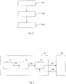
- Fig. 2 is a schematic flow diagram of a method for controlling an electric motor 20 of a hand tool 30 (see also Fig. 3 ).
- step 101 a target rotational speed S1 for the electric motor 20 is specified.
- the setpoint speed S1 is predetermined, for example, as a function of an actuation of a switch 7 of the handheld power tool 30 that can be actuated by a user.
- step 102 the predetermined setpoint speed S1 is varied by a value of a specific variation range for the provision of a varied setpoint speed S2 each time a time period has elapsed.
- the time duration for the variation of the predetermined setpoint speed S1 is set and the predetermined setpoint speed S1 is varied in each case after expiration of this fixed time duration.
- the fixed period of time can be before a first Commissioning of the power tool 30 are set and stored in the memory of the power tool 30.
- the predetermined target speed S1 can be varied in each case after a determinable period of time.
- the determinable time duration can be determined in each case by means of a random generator.
- the sequence of time consists of quasi-random time periods of different lengths.
- the value for varying the target speed S1 may be set, i. be determined a priori. Then, the predetermined target speed S1 is varied in each case after the expiration of a time period by the predetermined value for providing the varied target speed S2.
- a predefined desired rotational speed S1 can be incremented by the specified value after the expiration of a respective (2n) th time period and decremented by the specified value after the expiration of each (2n + 1) th time period (n ⁇ N).
- determinable values can also be used, which are determined by means of a random generator.
- the random number generator can determine the determinable value in each case after a period of time has elapsed, for example after the expiry of a defined period of time or else after the expiry of a time period determinable by means of a random generator.
- the predetermined setpoint speed S1 is preferably varied in each case after expiry of the time period by at least 50 rpm to provide the varied setpoint speed S2.
- the range of variation of the value for varying the target speed S1 is preferably determined by a 5% deviation of the predetermined target speed S1.
- step 103 the actual rotational speed of the electric motor is regulated to the provided varied target rotational speed.
- a manipulated variable S3 for the regulation of the varied target speed S2 to the actual speed S4 a phase angle is preferably used for a phase control of the electric motor 20.
- the proposed method is applicable, for example, to hand tool machines with carbon brush motors.
- Fig. 3 shows a schematic block diagram of an embodiment of an apparatus 10 for controlling an electric motor 20 of a hand tool 30.
- the device 10 of Fig. 2 has a presetting means 11, a variation means 12 and a control means 13.
- the presetting means 11 is arranged for presetting a target rotational speed S1 for the electric motor 20.
- the variation means 12 is set up to vary or change the predetermined target speed S1 each time a period of time has elapsed by a value of a specific variation range to provide a varied desired speed S2.
- the control means 13 is adapted to control an actual rotational speed S4 of the electric motor 20 to the provided varied target rotational speed S2.
- the control means 13 controls the electric motor 20 by means of a manipulated variable S3.
- the manipulated variable S3 is, for example, a phase angle of a phase control of the electric motor 20.
Landscapes
- Engineering & Computer Science (AREA)
- Mechanical Engineering (AREA)
- Power Engineering (AREA)
- Control Of Electric Motors In General (AREA)
- Drilling And Boring (AREA)
- Control Of Ac Motors In General (AREA)
Description
- Die vorliegende Erfindung betrifft ein Verfahren und eine Vorrichtung zum Regeln eines Elektromotors einer Handwerkzeugmaschine. Die Erfindung betrifft ferner eine Steuervorrichtung für eine Handwerkzeugmaschine mit einer solchen Vorrichtung sowie eine solche Handwerkzeugmaschine, insbesondere eine elektrische Handwerkzeugmaschine, wie zum Beispiel einen Elektroschrauber oder eine handgehaltene Bohrmaschine.
- Der Elektromotor der Handwerkzeugmaschine wird herkömmlicherweise mittels einer Drehzahlregelung auf eine Soll-Drehzahl geregelt.
- Allerdings arbeiten moderne Drehzahlregelungen mitunter so genau, dass durch Resonanzwirkungen die Kommutatoren von mechanisch kommutierten Motoren unrund werden. Dadurch kann der Kohleverschleiß des mechanisch kommutierten Motors übermäßig zunehmen. Durch die Zunahme des Kohleverschleißes reduziert sich die Nutzungsdauer des mechanisch kommutierten Motors der Handwerkzeugmaschine.
- Daher ist es eine Aufgabe der Erfindung, die Regelung eines Elektromotors einer Handwerkzeugmaschine zu verbessern.
- Dokument
EP-A-2241404 beschreibt alle Merkmale des Oberbegriffes des Anspruches 1 - Erfindungsgemäß wird ein Verfahren zum Regeln eines Elektromotors einer Handwerkzeugmaschine nach Anspruch 1 beschrieben. Durch das Variieren der Soll-Drehzahl kann die Ist-Drehzahl des Elektromotors gezielt variiert werden, insbesondere um einen bestimmten Arbeitspunkt gezielt variiert werden. Der Arbeitspunkt ist durch eine Betätigung eines durch einen Nutzer betätigbaren Schalters der Handwerkzeugmaschine bestimmt. Durch das gezielte Variieren der Ist-Drehzahl des Elektromotors werden Resonanzwirkungen an den Kommutatoren von mechanisch kommutierten Elektromotoren verhindert. Somit wird verhindert oder vermieden, dass die Kommutatoren der mechanisch kommutierten Motoren unrund werden, folglich wird auch ein übermäßiger Kohleverschleiß verhindert. Dadurch kann sich die Nutzungsdauer der Handwerkzeugmaschine erhöhen.
- Bei einer Ausführungsform wird die Soll-Drehzahl in Abhängigkeit von einer Betätigung eines durch einen Nutzer betätigbaren Schalters der Handwerkzeugmaschine vorgegeben.
- Somit gibt der Nutzer oder Anwender der Handwerkzeugmaschine die Soll-Drehzahl vor, die erfindungsgemäß um einen (kleinen) Wert des bestimmten Variationsbereiches variiert wird.
- Bei einer weiteren Ausführungsform hat das Verfahren die Schritte: Festlegen der Zeitdauer für das Variieren der vorgegebenen Soll-Drehzahl, und Variieren der vorgegeben Soll-Drehzahl jeweils nach Ablauf der festgelegten Zeitdauer.
- Die Zeitdauer, nach deren Ablauf die vorgegebene Soll-Drehzahl variiert wird, kann gemäß dieser Ausführungsform a priori festgelegt werden. Die festgelegte Zeitdauer kann in einem Speicher der Handwerkzeugmaschine abgelegt werden.
- Bei einer weiteren Ausführungsform hat das Verfahren die Schritte: Festlegen des Wertes für das Variieren der Soll-Drehzahl, und Variieren der vorgegebenen Soll-Drehzahl jeweils nach Ablauf einer Zeitdauer um den festgelegten Wert zur Bereitstellung der variierten Soll-Drehzahl.
- Der Wert oder Variationswert der Soll-Drehzahl kann a priori, d.h. vor der ersten Benutzung der Handwerkzeugmaschine, festgelegt werden. Dieser festgelegte Wert kann in dem Speicher der Handwerkzeugmaschine abgelegt werden.
- Bei einer weiteren Ausführungsform wird die vorgegebene Soll-Drehzahl nach Ablauf der jeweiligen (2n)-ten Zeitdauer um den festgelegten Wert inkrementiert und nach Ablauf jeder (2n+1)-ten Zeitdauer um den festgelegten Wert dekrementiert (n ∈ N). Somit wird die vorgegebene Soll-Drehzahl abwechselnd etwas erhöht und wieder erniedrigt. Dies stellt eine einfache Ausführungsform der Variation der Soll-Drehzahl dar. Die mittlere Drehzahl bleibt konstant. Die Zeitdauer ist größer als das Zehnfache einer Umlaufsdauer des Rotors.
- Bei einer weiteren Ausführungsform wird die vorgegebene Solldrehzahl jeweils nach Ablauf einer Zeitdauer um einen jeweiligen bestimmbaren Wert zur Bereitstellung der variierten Soll-Drehzahl variiert, wobei der jeweilige Wert mittels eines Zufallsgenerators bestimmt wird.
- Durch die hier vorgeschlagene Verwendung von durch einen Zufallsgenerator bestimmbaren Werten wird die Resonanzwirkung an den Kommutatoren eines mechanisch kommutierten Motors weiter vermindert.
- Weiterhin wird eine Vorrichtung zum Regeln eines Elektromotors einer Handwerkzeugmaschine nach dem Verfahren von Anspruch 1 beschrieben.
- Das jeweilige Mittel, Vorgabemittel, Variationsmittel und Regelungsmittel, kann hardwaretechnisch und/oder auch software-technisch implementiert sein. Bei einer hardwaretechnischen Implementierung kann das jeweilige Mittel als Vorrichtung oder als Teil einer Vorrichtung, zum Beispiel als Computer oder als Mikroprozessor ausgebildet sein. Bei einer software-technischen Implementierung kann das jeweilige Mittel als Computerprogrammprodukt, als eine Funktion, als eine Routine, als Teil eines Programmcodes oder als ausführbares Objekt ausgebildet sein.
- Außerdem wird eine Steuervorrichtung für eine Handwerkzeugmaschine vorgeschlagen, wobei die Steuervorrichtung die oben beschriebene Vorrichtung zum Regeln des Elektromotors der Handwerkzeugmaschine integriert. Die Vorrichtung ist damit Teil der auch als Schalter bezeichneten Steuervorrichtung der Handwerkzeugmaschine.
- Weiterhin wird eine Handwerkzeugmaschine mit einer solchen Vorrichtung vorgeschlagen. Die Handwerkzeugmaschine ist insbesondere eine elektrische Handwerkzeugmaschine, wie zum Beispiel ein Elektroschrauber, eine handgehaltene Bohrmaschine, ein Meißelhammer, ein Kombihammer, ein Akkuschrauber, eine Kreissäge oder eine Säbelsäge.
- Die nachfolgende Beschreibung erläutert die Erfindung anhand von exemplarischen Ausführungsformen und Figuren. In den Figuren zeigt:
-
Fig. 1 eine Handwerkzeugmaschine -
Fig. 2 ein schematisches Ablaufdiagramm eines Verfahrens zum Regeln eines Elektromotors einer Handwerkzeugmaschine; -
Fig. 3 ein schematisches Blockschaltbild eines Ausführungsbeispiels einer Vorrichtung zum Regeln eines Elektromotors einer Handwerkzeugmaschine; und - Gleiche oder funktionsgleiche Elemente werden durch gleiche Bezugszeichen in den Figuren indiziert, soweit nicht anders angegeben.
-
Fig. 1 zeigt eine beispielhafte Handwerkzeugmaschine 30, z.B. einen Elektroschrauber. Die Handwerkzeugmaschine hat eine Werkzeugaufnahme 2, in welche ein Werkzeug 3 einsetzbar oder befestigbar ist. Die Werkzeuge sind beispielsweise ein Schrauberbit, einen Bohrer, eine Schleifscheibe und ein Sägeblatt. Ein Elektromotor 20 treibt die Werkzeugaufnahme 2 an, hier beispielhaft um eine Arbeitsachse 4 drehend. Ein Antriebsstrang zwischen der Werkzeugaufnahme 2 und dem Elektromotor 20 kann eine Spindel 5, ein Getriebe 6 und weitere Komponenten, z.B. eine Drehmomentkupplung, ein Exzenterrad enthalten. - Ein Anwender nimmt die Handwerkzeugmaschine 30 durch Betätigen eines Schalters 7 in Betrieb. Der Schalter 7 ist vorzugsweise an einem Handgriff 8 angeordnet, mit welchem der Anwender die Handwerkzeugmaschine 30 halten und führen kann. Eine Steuerung 10 versorgt ansprechend auf das Betätigen den Elektromotor 20 mit Strom. Eine beispielhafte Stromquelle der Handwerkzeugmaschine 30 ist ein Batteriepaket 40 mit mehreren sekundären Batteriezellen 41.
- In
Fig. 2 ist ein schematisches Ablaufdiagramm eines Verfahrens zum Regeln eines Elektromotors 20 einer Handwerkzeugmaschine 30 (siehe auchFig. 3 ) dargestellt. - In Schritt 101 wird eine Soll-Drehzahl S1 für den Elektromotor 20 vorgegeben.
- Dabei wird die Soll-Drehzahl S1 beispielsweise in Abhängigkeit von einer Betätigung eines durch einen Nutzer betätigbaren Schalters 7 der Handwerkzeugmaschine 30 vorgegeben.
- In Schritt 102 wird die vorgegebene Soll-Drehzahl S1 jeweils nach Ablauf einer Zeitdauer um einen Wert eines bestimmten Variationsbereiches zur Bereitstellung einer variierten Soll-Drehzahl S2 variiert.
- Beispielsweise wird die Zeitdauer für das Variieren der vorgegebenen Soll-Drehzahl S1 festgelegt und die vorgegebene Soll-Drehzahl S1 wird jeweils nach Ablauf dieser festgelegten Zeitdauer variiert. Die festgelegte Zeitdauer kann insbesondere vor einer ersten Inbetriebnahme der Handwerkzeugmaschine 30 festgelegt werden und in dem Speicher der Handwerkzeugmaschine 30 abgelegt werden.
- Gemäß der beanspruchten Erfindung kann die vorgegebene Soll-Drehzahl S1 jeweils nach Ablauf einer bestimmbaren Zeitdauer variiert werden. Hierbei kann die bestimmbare Zeitdauer jeweils mittels eines Zufallsgenerators bestimmt werden. Damit besteht die Abfolge der Zeitdauer aus quasi-zufälligen Zeitdauern unterschiedlicher Länge.
- Ferner kann der Wert für das Variieren der Soll-Drehzahl S1 festgelegt, d.h. a priori bestimmt werden. Dann wird die vorgegebene Soll-Drehzahl S1 jeweils nach Ablauf einer Zeitdauer um den festgelegten Wert zur Bereitstellung der variierten Soll-Drehzahl S2 variiert. Hierbei kann beispielsweise eine vorgegebene Soll-Drehzahl S1 nach Ablauf einer jeweiligen (2n)-ten Zeitdauer um den festgelegten Wert inkrementiert werden und nach Ablauf jeder (2n+1)-ten Zeitdauer um den festgelegten Wert dekrementiert werden (n ∈ N). Als Alternative zur Verwendung festgelegter Werte können auch bestimmbare Werte eingesetzt werden, welche mittels eines Zufallsgenerators bestimmt werden. Hierbei kann der Zufallsgenerator den bestimmbaren Wert jeweils nach Ablauf einer Zeitdauer bestimmen, beispielsweise nach Ablauf einer festgelegten Zeitdauer oder auch nach Ablauf einer mittels eines Zufallsgenerators bestimmbaren Zeitdauer.
- Insgesamt wird die vorgegebene Soll-Drehzahl S1 vorzugsweise jeweils nach Ablauf der Zeitdauer um zumindest 50 U/min zur Bereitstellung der variierten Soll-Drehzahl S2 variiert. Der Variationsbereich für den Wert zum Variieren der Soll-Drehzahl S1 wird vorzugsweise durch eine 5%ige Abweichung der vorgegebenen Soll-Drehzahl S1 bestimmt.
- In Schritt 103 wird die Ist-Drehzahl des Elektromotors auf die bereitgestellte variierte Soll-Drehzahl geregelt. Als Stellgröße S3 für das Regeln der variierten Soll-Drehzahl S2 auf die Ist-Drehzahl S4 wird vorzugsweise ein Phasenwinkel für eine Phasenanschnittsteuerung des Elektromotors 20 verwendet.
- Das vorgeschlagene Verfahren ist beispielsweise auf Handwerkzeugmaschinen mit Kohlebürsten-Motoren anwendbar.
-
Fig. 3 zeigt ein schematisches Blockschaltbild eines Ausführungsbeispiels einer Vorrichtung 10 zum Regeln eines Elektromotors 20 einer Handwerkzeugmaschine 30. - Die Vorrichtung 10 der
Fig. 2 hat ein Vorgabemittel 11, ein Variationsmittel 12 und ein Regelungsmittel 13. Das Vorgabemittel 11 ist zum Vorgeben einer Soll-Drehzahl S1 für den Elektromotor 20 eingerichtet. Das Variationsmittel 12 ist dazu eingerichtet, die vorgegebene Soll-Drehzahl S1 jeweils nach Ablauf einer Zeitdauer um einen Wert eines bestimmten Variationsbereiches zur Bereitstellung einer variierten Soll-Drehzahl S2 zu variieren bzw. zu ändern. Das Regelungsmittel 13 ist dazu eingerichtet, eine Ist-Drehzahl S4 des Elektromotors 20 auf die bereitgestellte variierte Soll-Drehzahl S2 zu regeln. Dazu steuert das Regelungsmittel 13 den Elektromotor 20 mittels einer Stellgröße S3 an. Die Stellgröße S3 ist beispielsweise ein Phasenwinkel einer Phasenanschnittsteuerung des Elektromotors 20.
Claims (9)
- Verfahren zum Regeln eines Elektromotors (20) einer Handwerkzeugmaschine (30), mit:Vorgeben (101) einer Soll-Drehzahl (S1) für den Elektromotor (20),Variieren (102) der vorgegebenen Soll-Drehzahl (S1) jeweils nach Ablauf einer Zeitdauer um einen Wert eines bestimmten Variationsbereiches zur Bereitstellung einer variierten Soll-Drehzahl (S2), undRegeln (103) einer Ist-Drehzahl (S4) des Elektromotors (20) auf die bereitgestellte variierte Soll-Drehzahl (S2)dadurch gekennzeichnet, dass die vorgegebene Soll-Drehzahl (S1) jeweils nach Ablauf einer bestimmbaren Zeitdauer variiert wird, wobei die Zeitdauer jeweils mittels eines Zufallgenerators bestimmt wird.
- Verfahren nach Anspruch 1, dadurch gekennzeichnet, dass die Soll-Drehzahl (S1) in Abhängigkeit von einer Betätigung eines durch einen Nutzer betätigbaren Schalters (7) der Handwerkzeugmaschine (30) vorgegeben wird.
- Verfahren nach Anspruch 1 oder 2, gekennzeichnet durch
Festlegen der Zeitdauer für das Variieren der vorgegebenen Soll-Drehzahl (S1), und Variieren der vorgegeben Soll-Drehzahl (S1) jeweils nach Ablauf der festgelegten Zeitdauer. - Verfahren nach einem der Ansprüche 1 bis 3, gekennzeichnet durch
Festlegen des Wertes für das Variieren der Soll-Drehzahl (S1), und
Variieren der vorgegebenen Soll-Drehzahl (S1) jeweils nach Ablauf einer Zeitdauer um den festgelegten Wert zur Bereitstellung der variierten Soll-Drehzahl (S2). - Verfahren nach Anspruch 4, dadurch gekennzeichnet, dass die vorgegebene Soll-Drehzahl (S1) nach Ablauf der jeweiligen (2n)-ten Zeitdauer um den festgelegten Wert inkrementiert wird und nach Ablauf jeder (2n+1)-ten Zeitdauer um den festgelegten Wert dekrementiert wird, mit n ∈ N.
- Verfahren nach einem der Ansprüche 1 bis 3, dadurch gekennzeichnet, dass die vorgegebene Solldrehzahl (S1) jeweils nach Ablauf einer Zeitdauer um einen jeweiligen bestimmbaren Wert zur Bereitstellung der variierten Soll-Drehzahl (S2) variiert wird, wobei der jeweilige Wert mittels eines Zufallsgenerators bestimmt wird.
- Vorrichtung (10) zum Regeln eines Elektromotors (20) einer Handwerkzeugmaschine (30), nach dem Verfahren von Anspruch 1.
- Steuervorrichtung für eine Handwerkzeugmaschine (30), wobei die Steuervorrichtung eine Vorrichtung (10) nach Anspruch 7 integriert.
- Handwerkzeugmaschine (30) mit einer Vorrichtung (10) zum Ansteuern eines Elektromotors (20) der Handwerkzeugmaschine (30) nach Anspruch 7.
Applications Claiming Priority (2)
| Application Number | Priority Date | Filing Date | Title |
|---|---|---|---|
| DE102012214975.9A DE102012214975A1 (de) | 2012-08-23 | 2012-08-23 | Verfahren und Vorrichtung zum Regeln eines Elektromotors einer Handwerkzeugmaschine |
| PCT/EP2013/067357 WO2014029795A2 (de) | 2012-08-23 | 2013-08-21 | Verfahren und vorrichtung zum regeln eines elektromotors einer handwerkzeugmaschine |
Publications (2)
| Publication Number | Publication Date |
|---|---|
| EP2888811A2 EP2888811A2 (de) | 2015-07-01 |
| EP2888811B1 true EP2888811B1 (de) | 2017-01-18 |
Family
ID=49035577
Family Applications (1)
| Application Number | Title | Priority Date | Filing Date |
|---|---|---|---|
| EP13753163.8A Active EP2888811B1 (de) | 2012-08-23 | 2013-08-21 | Verfahren und vorrichtung zum regeln eines elektromotors einer handwerkzeugmaschine |
Country Status (6)
| Country | Link |
|---|---|
| US (1) | US20150229256A1 (de) |
| EP (1) | EP2888811B1 (de) |
| JP (1) | JP6294322B2 (de) |
| CN (1) | CN104737437B (de) |
| DE (1) | DE102012214975A1 (de) |
| WO (1) | WO2014029795A2 (de) |
Families Citing this family (2)
| Publication number | Priority date | Publication date | Assignee | Title |
|---|---|---|---|---|
| WO2015061370A1 (en) | 2013-10-21 | 2015-04-30 | Milwaukee Electric Tool Corporation | Adapter for power tool devices |
| EP3881992A1 (de) * | 2020-03-20 | 2021-09-22 | Andreas Stihl AG & Co. KG | Handgetragenes garten-, forst- und/oder baubearbeitungsgerät und verfahren zum betreiben eines handgetragenen garten- forst- und/oder baubearbeitungsgeräts |
Family Cites Families (10)
| Publication number | Priority date | Publication date | Assignee | Title |
|---|---|---|---|---|
| JPH1159467A (ja) * | 1997-08-26 | 1999-03-02 | Koyo Seiko Co Ltd | パワーステアリング装置 |
| US6433507B1 (en) * | 2000-02-18 | 2002-08-13 | Siemens Automotive Inc. | Spread spectrum motor control circuit |
| US6674962B2 (en) * | 2002-01-29 | 2004-01-06 | Siemens Vdo Automotive, Inc. | Limited-pool random frequency for DC brush motor low frequency PWM speed control |
| JP4939065B2 (ja) * | 2006-01-20 | 2012-05-23 | リョービ株式会社 | 携帯用電動切断工具の速度制御装置 |
| WO2008056771A1 (en) * | 2006-11-10 | 2008-05-15 | Jtekt Corporation | Electric power steering device |
| FR2944464B1 (fr) * | 2009-04-17 | 2011-04-08 | Renault Georges Ets | Procede pour adapter automatiquement la vitesse de vissage d'un outil de vissage par paliers successifs et outillage correspondant. |
| FR2954377B1 (fr) * | 2009-12-18 | 2015-03-13 | Zodiac Pool Care Europe | Appareil nettoyeur de surface immergee a moteur electrique unique reversible d'entrainement et de pompage |
| JP5534327B2 (ja) * | 2010-05-19 | 2014-06-25 | 日立工機株式会社 | 電動工具 |
| JP5491346B2 (ja) * | 2010-10-13 | 2014-05-14 | 株式会社マキタ | 電動工具およびプログラム |
| US8786233B2 (en) * | 2011-04-27 | 2014-07-22 | Medtronic Xomed, Inc. | Electric ratchet for a powered screwdriver |
-
2012
- 2012-08-23 DE DE102012214975.9A patent/DE102012214975A1/de not_active Withdrawn
-
2013
- 2013-08-21 JP JP2015527900A patent/JP6294322B2/ja active Active
- 2013-08-21 WO PCT/EP2013/067357 patent/WO2014029795A2/de not_active Ceased
- 2013-08-21 EP EP13753163.8A patent/EP2888811B1/de active Active
- 2013-08-21 US US14/423,018 patent/US20150229256A1/en not_active Abandoned
- 2013-08-21 CN CN201380050542.3A patent/CN104737437B/zh active Active
Non-Patent Citations (1)
| Title |
|---|
| None * |
Also Published As
| Publication number | Publication date |
|---|---|
| CN104737437B (zh) | 2017-07-28 |
| US20150229256A1 (en) | 2015-08-13 |
| EP2888811A2 (de) | 2015-07-01 |
| DE102012214975A1 (de) | 2014-02-27 |
| JP6294322B2 (ja) | 2018-03-14 |
| WO2014029795A2 (de) | 2014-02-27 |
| CN104737437A (zh) | 2015-06-24 |
| JP2015530933A (ja) | 2015-10-29 |
| WO2014029795A3 (de) | 2015-03-19 |
Similar Documents
| Publication | Publication Date | Title |
|---|---|---|
| DE102011104901B4 (de) | Kraftgetriebene Handwerkzeugmaschine | |
| EP3113911B1 (de) | Adaptive leistungsanzeige | |
| EP1443176A1 (de) | Vorschubgeregelte Kernbohrmaschine | |
| DE102012202116A1 (de) | System mit einem Einsatzwerkzeug und einer Handwerkzeugmaschine | |
| EP3856462B1 (de) | Verfahren zur steuerung oder regelung einer handwerkzeugmaschine | |
| EP4368346A1 (de) | Verfahren zum betrieb einer handwerkzeugmaschine | |
| EP4061580A1 (de) | Verfahren zum betreiben einer werkzeugmaschine und werkzeugmaschine | |
| EP1425475B1 (de) | Bodenschneidvorrichtung | |
| EP2888811A2 (de) | Verfahren und vorrichtung zum regeln eines elektromotors einer handwerkzeugmaschine | |
| DE102023200618A1 (de) | Verfahren zum Auswählen von Daten für ein Training einer künstlichen Intelligenz, Verfahren zum Erzeugen eines Trainingsdatensatzes, Trainingsdatensatz | |
| EP3854556A1 (de) | Verfahren zum betreiben eines handgeführten bearbeitungsgeräts und handgeführtes bearbeitungsgerät | |
| DE102023200607A1 (de) | Verfahren zum Steuern einer Handwerkzeugmaschine und Handwerkzeugmaschine | |
| WO2021063740A1 (de) | Verfahren zum effizienten entladen eines akkumulators | |
| DE102012214977A1 (de) | Verfahren und Vorrichtung zum Ansteuern eines Elektromotors einer Handwerkzeugmaschine | |
| DE102023200615A1 (de) | Verfahren zum Auswählen von Daten für ein Training einer künstlichen Intelligenz, Verfahren zum Erzeugen eines Trainingsdatensatzes, Trainingsdatensatz | |
| DE102023200619A1 (de) | Verfahren zum Auswählen von Daten für ein Training einer künstlichen Intelligenz, Verfahren zum Erzeugen eines Trainingsdatensatzes, Trainingsdatensatz | |
| DE102021121777B4 (de) | Verfahren zum Betreiben eines Trockenbauschraubers, Computerprogramm und Trockenbauschrauber | |
| WO2014056828A2 (de) | Verfahren und vorrichtung für einen tiefentladeschutz eines akkumulators einer handwerkzeugmaschine | |
| EP2903785A1 (de) | Verfahren und vorrichtung zum betreiben einer handwerkzeugmaschine mit einem tangentialschlagwerk | |
| DE102013210926A1 (de) | Elektronikvorrichtung | |
| EP2301714B1 (de) | Planschleifmaschine und Verfahren zum Betrieb und/oder zur Wartung einer Planschleifmaschine | |
| DE102014222567A1 (de) | Handwerkzeugmaschinenvorrichtung | |
| DE102016210219A1 (de) | Werkzeugmaschinenvorrichtung | |
| EP4484042A1 (de) | Verfahren und elektrowerkzeug zum gewindeformen | |
| DE10352500A1 (de) | Handwerkzeugmaschine |
Legal Events
| Date | Code | Title | Description |
|---|---|---|---|
| PUAI | Public reference made under article 153(3) epc to a published international application that has entered the european phase |
Free format text: ORIGINAL CODE: 0009012 |
|
| 17P | Request for examination filed |
Effective date: 20150323 |
|
| AK | Designated contracting states |
Kind code of ref document: A2 Designated state(s): AL AT BE BG CH CY CZ DE DK EE ES FI FR GB GR HR HU IE IS IT LI LT LU LV MC MK MT NL NO PL PT RO RS SE SI SK SM TR |
|
| AX | Request for extension of the european patent |
Extension state: BA ME |
|
| R17P | Request for examination filed (corrected) |
Effective date: 20150921 |
|
| RBV | Designated contracting states (corrected) |
Designated state(s): AL AT BE BG CH CY CZ DE DK EE ES FI FR GB GR HR HU IE IS IT LI LT LU LV MC MK MT NL NO PL PT RO RS SE SI SK SM TR |
|
| DAX | Request for extension of the european patent (deleted) | ||
| REG | Reference to a national code |
Ref country code: DE Ref legal event code: R079 Ref document number: 502013006162 Country of ref document: DE Free format text: PREVIOUS MAIN CLASS: H02P0006080000 Ipc: H02P0007240000 |
|
| GRAP | Despatch of communication of intention to grant a patent |
Free format text: ORIGINAL CODE: EPIDOSNIGR1 |
|
| RIC1 | Information provided on ipc code assigned before grant |
Ipc: H02P 7/24 20060101AFI20160822BHEP Ipc: H02K 7/14 20060101ALI20160822BHEP Ipc: B25B 21/00 20060101ALI20160822BHEP Ipc: B25F 5/00 20060101ALI20160822BHEP |
|
| INTG | Intention to grant announced |
Effective date: 20160921 |
|
| GRAS | Grant fee paid |
Free format text: ORIGINAL CODE: EPIDOSNIGR3 |
|
| GRAA | (expected) grant |
Free format text: ORIGINAL CODE: 0009210 |
|
| AK | Designated contracting states |
Kind code of ref document: B1 Designated state(s): AL AT BE BG CH CY CZ DE DK EE ES FI FR GB GR HR HU IE IS IT LI LT LU LV MC MK MT NL NO PL PT RO RS SE SI SK SM TR |
|
| REG | Reference to a national code |
Ref country code: GB Ref legal event code: FG4D Free format text: NOT ENGLISH |
|
| REG | Reference to a national code |
Ref country code: CH Ref legal event code: EP |
|
| REG | Reference to a national code |
Ref country code: AT Ref legal event code: REF Ref document number: 863426 Country of ref document: AT Kind code of ref document: T Effective date: 20170215 |
|
| REG | Reference to a national code |
Ref country code: IE Ref legal event code: FG4D Free format text: LANGUAGE OF EP DOCUMENT: GERMAN |
|
| REG | Reference to a national code |
Ref country code: DE Ref legal event code: R096 Ref document number: 502013006162 Country of ref document: DE |
|
| REG | Reference to a national code |
Ref country code: NL Ref legal event code: MP Effective date: 20170118 |
|
| REG | Reference to a national code |
Ref country code: LT Ref legal event code: MG4D |
|
| PG25 | Lapsed in a contracting state [announced via postgrant information from national office to epo] |
Ref country code: NL Free format text: LAPSE BECAUSE OF FAILURE TO SUBMIT A TRANSLATION OF THE DESCRIPTION OR TO PAY THE FEE WITHIN THE PRESCRIBED TIME-LIMIT Effective date: 20170118 |
|
| REG | Reference to a national code |
Ref country code: FR Ref legal event code: PLFP Year of fee payment: 5 |
|
| PG25 | Lapsed in a contracting state [announced via postgrant information from national office to epo] |
Ref country code: IS Free format text: LAPSE BECAUSE OF FAILURE TO SUBMIT A TRANSLATION OF THE DESCRIPTION OR TO PAY THE FEE WITHIN THE PRESCRIBED TIME-LIMIT Effective date: 20170518 Ref country code: NO Free format text: LAPSE BECAUSE OF FAILURE TO SUBMIT A TRANSLATION OF THE DESCRIPTION OR TO PAY THE FEE WITHIN THE PRESCRIBED TIME-LIMIT Effective date: 20170418 Ref country code: GR Free format text: LAPSE BECAUSE OF FAILURE TO SUBMIT A TRANSLATION OF THE DESCRIPTION OR TO PAY THE FEE WITHIN THE PRESCRIBED TIME-LIMIT Effective date: 20170419 Ref country code: FI Free format text: LAPSE BECAUSE OF FAILURE TO SUBMIT A TRANSLATION OF THE DESCRIPTION OR TO PAY THE FEE WITHIN THE PRESCRIBED TIME-LIMIT Effective date: 20170118 Ref country code: HR Free format text: LAPSE BECAUSE OF FAILURE TO SUBMIT A TRANSLATION OF THE DESCRIPTION OR TO PAY THE FEE WITHIN THE PRESCRIBED TIME-LIMIT Effective date: 20170118 Ref country code: LT Free format text: LAPSE BECAUSE OF FAILURE TO SUBMIT A TRANSLATION OF THE DESCRIPTION OR TO PAY THE FEE WITHIN THE PRESCRIBED TIME-LIMIT Effective date: 20170118 |
|
| PG25 | Lapsed in a contracting state [announced via postgrant information from national office to epo] |
Ref country code: PT Free format text: LAPSE BECAUSE OF FAILURE TO SUBMIT A TRANSLATION OF THE DESCRIPTION OR TO PAY THE FEE WITHIN THE PRESCRIBED TIME-LIMIT Effective date: 20170518 Ref country code: PL Free format text: LAPSE BECAUSE OF FAILURE TO SUBMIT A TRANSLATION OF THE DESCRIPTION OR TO PAY THE FEE WITHIN THE PRESCRIBED TIME-LIMIT Effective date: 20170118 Ref country code: LV Free format text: LAPSE BECAUSE OF FAILURE TO SUBMIT A TRANSLATION OF THE DESCRIPTION OR TO PAY THE FEE WITHIN THE PRESCRIBED TIME-LIMIT Effective date: 20170118 Ref country code: SE Free format text: LAPSE BECAUSE OF FAILURE TO SUBMIT A TRANSLATION OF THE DESCRIPTION OR TO PAY THE FEE WITHIN THE PRESCRIBED TIME-LIMIT Effective date: 20170118 Ref country code: BG Free format text: LAPSE BECAUSE OF FAILURE TO SUBMIT A TRANSLATION OF THE DESCRIPTION OR TO PAY THE FEE WITHIN THE PRESCRIBED TIME-LIMIT Effective date: 20170418 Ref country code: ES Free format text: LAPSE BECAUSE OF FAILURE TO SUBMIT A TRANSLATION OF THE DESCRIPTION OR TO PAY THE FEE WITHIN THE PRESCRIBED TIME-LIMIT Effective date: 20170118 Ref country code: RS Free format text: LAPSE BECAUSE OF FAILURE TO SUBMIT A TRANSLATION OF THE DESCRIPTION OR TO PAY THE FEE WITHIN THE PRESCRIBED TIME-LIMIT Effective date: 20170118 |
|
| REG | Reference to a national code |
Ref country code: DE Ref legal event code: R097 Ref document number: 502013006162 Country of ref document: DE |
|
| PG25 | Lapsed in a contracting state [announced via postgrant information from national office to epo] |
Ref country code: CZ Free format text: LAPSE BECAUSE OF FAILURE TO SUBMIT A TRANSLATION OF THE DESCRIPTION OR TO PAY THE FEE WITHIN THE PRESCRIBED TIME-LIMIT Effective date: 20170118 Ref country code: RO Free format text: LAPSE BECAUSE OF FAILURE TO SUBMIT A TRANSLATION OF THE DESCRIPTION OR TO PAY THE FEE WITHIN THE PRESCRIBED TIME-LIMIT Effective date: 20170118 Ref country code: SK Free format text: LAPSE BECAUSE OF FAILURE TO SUBMIT A TRANSLATION OF THE DESCRIPTION OR TO PAY THE FEE WITHIN THE PRESCRIBED TIME-LIMIT Effective date: 20170118 Ref country code: IT Free format text: LAPSE BECAUSE OF FAILURE TO SUBMIT A TRANSLATION OF THE DESCRIPTION OR TO PAY THE FEE WITHIN THE PRESCRIBED TIME-LIMIT Effective date: 20170118 Ref country code: EE Free format text: LAPSE BECAUSE OF FAILURE TO SUBMIT A TRANSLATION OF THE DESCRIPTION OR TO PAY THE FEE WITHIN THE PRESCRIBED TIME-LIMIT Effective date: 20170118 |
|
| PLBE | No opposition filed within time limit |
Free format text: ORIGINAL CODE: 0009261 |
|
| STAA | Information on the status of an ep patent application or granted ep patent |
Free format text: STATUS: NO OPPOSITION FILED WITHIN TIME LIMIT |
|
| PG25 | Lapsed in a contracting state [announced via postgrant information from national office to epo] |
Ref country code: DK Free format text: LAPSE BECAUSE OF FAILURE TO SUBMIT A TRANSLATION OF THE DESCRIPTION OR TO PAY THE FEE WITHIN THE PRESCRIBED TIME-LIMIT Effective date: 20170118 Ref country code: SM Free format text: LAPSE BECAUSE OF FAILURE TO SUBMIT A TRANSLATION OF THE DESCRIPTION OR TO PAY THE FEE WITHIN THE PRESCRIBED TIME-LIMIT Effective date: 20170118 |
|
| 26N | No opposition filed |
Effective date: 20171019 |
|
| PG25 | Lapsed in a contracting state [announced via postgrant information from national office to epo] |
Ref country code: SI Free format text: LAPSE BECAUSE OF FAILURE TO SUBMIT A TRANSLATION OF THE DESCRIPTION OR TO PAY THE FEE WITHIN THE PRESCRIBED TIME-LIMIT Effective date: 20170118 |
|
| REG | Reference to a national code |
Ref country code: CH Ref legal event code: PL |
|
| PG25 | Lapsed in a contracting state [announced via postgrant information from national office to epo] |
Ref country code: MC Free format text: LAPSE BECAUSE OF FAILURE TO SUBMIT A TRANSLATION OF THE DESCRIPTION OR TO PAY THE FEE WITHIN THE PRESCRIBED TIME-LIMIT Effective date: 20170118 |
|
| PG25 | Lapsed in a contracting state [announced via postgrant information from national office to epo] |
Ref country code: LI Free format text: LAPSE BECAUSE OF NON-PAYMENT OF DUE FEES Effective date: 20170831 Ref country code: CH Free format text: LAPSE BECAUSE OF NON-PAYMENT OF DUE FEES Effective date: 20170831 |
|
| REG | Reference to a national code |
Ref country code: IE Ref legal event code: MM4A |
|
| REG | Reference to a national code |
Ref country code: BE Ref legal event code: MM Effective date: 20170831 |
|
| PG25 | Lapsed in a contracting state [announced via postgrant information from national office to epo] |
Ref country code: LU Free format text: LAPSE BECAUSE OF NON-PAYMENT OF DUE FEES Effective date: 20170821 |
|
| PG25 | Lapsed in a contracting state [announced via postgrant information from national office to epo] |
Ref country code: IE Free format text: LAPSE BECAUSE OF NON-PAYMENT OF DUE FEES Effective date: 20170821 |
|
| REG | Reference to a national code |
Ref country code: FR Ref legal event code: PLFP Year of fee payment: 6 |
|
| PG25 | Lapsed in a contracting state [announced via postgrant information from national office to epo] |
Ref country code: BE Free format text: LAPSE BECAUSE OF NON-PAYMENT OF DUE FEES Effective date: 20170831 |
|
| PG25 | Lapsed in a contracting state [announced via postgrant information from national office to epo] |
Ref country code: MT Free format text: LAPSE BECAUSE OF FAILURE TO SUBMIT A TRANSLATION OF THE DESCRIPTION OR TO PAY THE FEE WITHIN THE PRESCRIBED TIME-LIMIT Effective date: 20170118 |
|
| PG25 | Lapsed in a contracting state [announced via postgrant information from national office to epo] |
Ref country code: HU Free format text: LAPSE BECAUSE OF FAILURE TO SUBMIT A TRANSLATION OF THE DESCRIPTION OR TO PAY THE FEE WITHIN THE PRESCRIBED TIME-LIMIT; INVALID AB INITIO Effective date: 20130821 |
|
| REG | Reference to a national code |
Ref country code: AT Ref legal event code: MM01 Ref document number: 863426 Country of ref document: AT Kind code of ref document: T Effective date: 20180821 |
|
| PG25 | Lapsed in a contracting state [announced via postgrant information from national office to epo] |
Ref country code: CY Free format text: LAPSE BECAUSE OF FAILURE TO SUBMIT A TRANSLATION OF THE DESCRIPTION OR TO PAY THE FEE WITHIN THE PRESCRIBED TIME-LIMIT Effective date: 20170118 |
|
| PG25 | Lapsed in a contracting state [announced via postgrant information from national office to epo] |
Ref country code: MK Free format text: LAPSE BECAUSE OF FAILURE TO SUBMIT A TRANSLATION OF THE DESCRIPTION OR TO PAY THE FEE WITHIN THE PRESCRIBED TIME-LIMIT Effective date: 20170118 |
|
| PG25 | Lapsed in a contracting state [announced via postgrant information from national office to epo] |
Ref country code: AT Free format text: LAPSE BECAUSE OF NON-PAYMENT OF DUE FEES Effective date: 20180821 |
|
| PG25 | Lapsed in a contracting state [announced via postgrant information from national office to epo] |
Ref country code: TR Free format text: LAPSE BECAUSE OF FAILURE TO SUBMIT A TRANSLATION OF THE DESCRIPTION OR TO PAY THE FEE WITHIN THE PRESCRIBED TIME-LIMIT Effective date: 20170118 |
|
| PG25 | Lapsed in a contracting state [announced via postgrant information from national office to epo] |
Ref country code: AL Free format text: LAPSE BECAUSE OF FAILURE TO SUBMIT A TRANSLATION OF THE DESCRIPTION OR TO PAY THE FEE WITHIN THE PRESCRIBED TIME-LIMIT Effective date: 20170118 |
|
| P01 | Opt-out of the competence of the unified patent court (upc) registered |
Effective date: 20230830 |
|
| PGFP | Annual fee paid to national office [announced via postgrant information from national office to epo] |
Ref country code: DE Payment date: 20240821 Year of fee payment: 12 |
|
| PGFP | Annual fee paid to national office [announced via postgrant information from national office to epo] |
Ref country code: GB Payment date: 20240826 Year of fee payment: 12 |
|
| PGFP | Annual fee paid to national office [announced via postgrant information from national office to epo] |
Ref country code: FR Payment date: 20240829 Year of fee payment: 12 |
|
| REG | Reference to a national code |
Ref country code: DE Ref legal event code: R119 Ref document number: 502013006162 Country of ref document: DE |
|
| GBPC | Gb: european patent ceased through non-payment of renewal fee |
Effective date: 20250821 |