EP2886942A1 - Lighting device - Google Patents
Lighting device Download PDFInfo
- Publication number
- EP2886942A1 EP2886942A1 EP14197788.4A EP14197788A EP2886942A1 EP 2886942 A1 EP2886942 A1 EP 2886942A1 EP 14197788 A EP14197788 A EP 14197788A EP 2886942 A1 EP2886942 A1 EP 2886942A1
- Authority
- EP
- European Patent Office
- Prior art keywords
- reflector
- support
- lighting device
- diffuser
- light
- Prior art date
- Legal status (The legal status is an assumption and is not a legal conclusion. Google has not performed a legal analysis and makes no representation as to the accuracy of the status listed.)
- Withdrawn
Links
Images


Classifications
-
- F—MECHANICAL ENGINEERING; LIGHTING; HEATING; WEAPONS; BLASTING
- F21—LIGHTING
- F21V—FUNCTIONAL FEATURES OR DETAILS OF LIGHTING DEVICES OR SYSTEMS THEREOF; STRUCTURAL COMBINATIONS OF LIGHTING DEVICES WITH OTHER ARTICLES, NOT OTHERWISE PROVIDED FOR
- F21V23/00—Arrangement of electric circuit elements in or on lighting devices
- F21V23/003—Arrangement of electric circuit elements in or on lighting devices the elements being electronics drivers or controllers for operating the light source, e.g. for a LED array
- F21V23/007—Arrangement of electric circuit elements in or on lighting devices the elements being electronics drivers or controllers for operating the light source, e.g. for a LED array enclosed in a casing
- F21V23/009—Arrangement of electric circuit elements in or on lighting devices the elements being electronics drivers or controllers for operating the light source, e.g. for a LED array enclosed in a casing the casing being inside the housing of the lighting device
-
- F—MECHANICAL ENGINEERING; LIGHTING; HEATING; WEAPONS; BLASTING
- F21—LIGHTING
- F21V—FUNCTIONAL FEATURES OR DETAILS OF LIGHTING DEVICES OR SYSTEMS THEREOF; STRUCTURAL COMBINATIONS OF LIGHTING DEVICES WITH OTHER ARTICLES, NOT OTHERWISE PROVIDED FOR
- F21V13/00—Producing particular characteristics or distribution of the light emitted by means of a combination of elements specified in two or more of main groups F21V1/00 - F21V11/00
- F21V13/12—Combinations of only three kinds of elements
-
- F—MECHANICAL ENGINEERING; LIGHTING; HEATING; WEAPONS; BLASTING
- F21—LIGHTING
- F21V—FUNCTIONAL FEATURES OR DETAILS OF LIGHTING DEVICES OR SYSTEMS THEREOF; STRUCTURAL COMBINATIONS OF LIGHTING DEVICES WITH OTHER ARTICLES, NOT OTHERWISE PROVIDED FOR
- F21V15/00—Protecting lighting devices from damage
- F21V15/01—Housings, e.g. material or assembling of housing parts
-
- F—MECHANICAL ENGINEERING; LIGHTING; HEATING; WEAPONS; BLASTING
- F21—LIGHTING
- F21V—FUNCTIONAL FEATURES OR DETAILS OF LIGHTING DEVICES OR SYSTEMS THEREOF; STRUCTURAL COMBINATIONS OF LIGHTING DEVICES WITH OTHER ARTICLES, NOT OTHERWISE PROVIDED FOR
- F21V7/00—Reflectors for light sources
- F21V7/04—Optical design
-
- F—MECHANICAL ENGINEERING; LIGHTING; HEATING; WEAPONS; BLASTING
- F21—LIGHTING
- F21S—NON-PORTABLE LIGHTING DEVICES; SYSTEMS THEREOF; VEHICLE LIGHTING DEVICES SPECIALLY ADAPTED FOR VEHICLE EXTERIORS
- F21S8/00—Lighting devices intended for fixed installation
- F21S8/04—Lighting devices intended for fixed installation intended only for mounting on a ceiling or the like overhead structures
-
- F—MECHANICAL ENGINEERING; LIGHTING; HEATING; WEAPONS; BLASTING
- F21—LIGHTING
- F21S—NON-PORTABLE LIGHTING DEVICES; SYSTEMS THEREOF; VEHICLE LIGHTING DEVICES SPECIALLY ADAPTED FOR VEHICLE EXTERIORS
- F21S9/00—Lighting devices with a built-in power supply; Systems employing lighting devices with a built-in power supply
- F21S9/02—Lighting devices with a built-in power supply; Systems employing lighting devices with a built-in power supply the power supply being a battery or accumulator
-
- F—MECHANICAL ENGINEERING; LIGHTING; HEATING; WEAPONS; BLASTING
- F21—LIGHTING
- F21V—FUNCTIONAL FEATURES OR DETAILS OF LIGHTING DEVICES OR SYSTEMS THEREOF; STRUCTURAL COMBINATIONS OF LIGHTING DEVICES WITH OTHER ARTICLES, NOT OTHERWISE PROVIDED FOR
- F21V23/00—Arrangement of electric circuit elements in or on lighting devices
- F21V23/04—Arrangement of electric circuit elements in or on lighting devices the elements being switches
- F21V23/0442—Arrangement of electric circuit elements in or on lighting devices the elements being switches activated by means of a sensor, e.g. motion or photodetectors
- F21V23/0471—Arrangement of electric circuit elements in or on lighting devices the elements being switches activated by means of a sensor, e.g. motion or photodetectors the sensor detecting the proximity, the presence or the movement of an object or a person
-
- F—MECHANICAL ENGINEERING; LIGHTING; HEATING; WEAPONS; BLASTING
- F21—LIGHTING
- F21V—FUNCTIONAL FEATURES OR DETAILS OF LIGHTING DEVICES OR SYSTEMS THEREOF; STRUCTURAL COMBINATIONS OF LIGHTING DEVICES WITH OTHER ARTICLES, NOT OTHERWISE PROVIDED FOR
- F21V29/00—Protecting lighting devices from thermal damage; Cooling or heating arrangements specially adapted for lighting devices or systems
- F21V29/50—Cooling arrangements
- F21V29/70—Cooling arrangements characterised by passive heat-dissipating elements, e.g. heat-sinks
- F21V29/74—Cooling arrangements characterised by passive heat-dissipating elements, e.g. heat-sinks with fins or blades
-
- F—MECHANICAL ENGINEERING; LIGHTING; HEATING; WEAPONS; BLASTING
- F21—LIGHTING
- F21V—FUNCTIONAL FEATURES OR DETAILS OF LIGHTING DEVICES OR SYSTEMS THEREOF; STRUCTURAL COMBINATIONS OF LIGHTING DEVICES WITH OTHER ARTICLES, NOT OTHERWISE PROVIDED FOR
- F21V3/00—Globes; Bowls; Cover glasses
- F21V3/04—Globes; Bowls; Cover glasses characterised by materials, surface treatments or coatings
- F21V3/049—Patterns or structured surfaces for diffusing light, e.g. frosted surfaces
-
- F—MECHANICAL ENGINEERING; LIGHTING; HEATING; WEAPONS; BLASTING
- F21—LIGHTING
- F21V—FUNCTIONAL FEATURES OR DETAILS OF LIGHTING DEVICES OR SYSTEMS THEREOF; STRUCTURAL COMBINATIONS OF LIGHTING DEVICES WITH OTHER ARTICLES, NOT OTHERWISE PROVIDED FOR
- F21V7/00—Reflectors for light sources
- F21V7/005—Reflectors for light sources with an elongated shape to cooperate with linear light sources
-
- F—MECHANICAL ENGINEERING; LIGHTING; HEATING; WEAPONS; BLASTING
- F21—LIGHTING
- F21Y—INDEXING SCHEME ASSOCIATED WITH SUBCLASSES F21K, F21L, F21S and F21V, RELATING TO THE FORM OR THE KIND OF THE LIGHT SOURCES OR OF THE COLOUR OF THE LIGHT EMITTED
- F21Y2103/00—Elongate light sources, e.g. fluorescent tubes
- F21Y2103/10—Elongate light sources, e.g. fluorescent tubes comprising a linear array of point-like light-generating elements
-
- F—MECHANICAL ENGINEERING; LIGHTING; HEATING; WEAPONS; BLASTING
- F21—LIGHTING
- F21Y—INDEXING SCHEME ASSOCIATED WITH SUBCLASSES F21K, F21L, F21S and F21V, RELATING TO THE FORM OR THE KIND OF THE LIGHT SOURCES OR OF THE COLOUR OF THE LIGHT EMITTED
- F21Y2103/00—Elongate light sources, e.g. fluorescent tubes
- F21Y2103/30—Elongate light sources, e.g. fluorescent tubes curved
- F21Y2103/33—Elongate light sources, e.g. fluorescent tubes curved annular
-
- F—MECHANICAL ENGINEERING; LIGHTING; HEATING; WEAPONS; BLASTING
- F21—LIGHTING
- F21Y—INDEXING SCHEME ASSOCIATED WITH SUBCLASSES F21K, F21L, F21S and F21V, RELATING TO THE FORM OR THE KIND OF THE LIGHT SOURCES OR OF THE COLOUR OF THE LIGHT EMITTED
- F21Y2115/00—Light-generating elements of semiconductor light sources
- F21Y2115/10—Light-emitting diodes [LED]
Definitions
- the present invention relates to a lighting device.
- Lighting devices such as ambient lighting for public or private premises such as corridors, or security lighting, are well known.
- a problem encountered in this type of lighting device is that of its size. Indeed, plus a device is salient with respect to a wall that supports it, such as a wall or a ceiling, and its volume, will have an unsightly effect for a user. For this, one of the manufacturing constraints of such a lighting device is that the device is as flat as possible so as to limit its projection relative to the wall.
- the reduction in the size of a lighting device generally forces these devices to glare problems due to the lighting itself. Indeed, and in particular when light sources are placed at a very short distance from a surface of a diffuser, it appears in this case as many "tasks" lights that light sources on said diffuser which will then be visible by the user. In addition, the light intensity is in this case too important and may dazzle its user.
- LEDs light emitting diodes
- a lens indeed makes it possible to concentrate the luminous flux but causes however a strong dazzle. It is always possible to remove the lens of the diffuser but this is only feasible to the detriment of its size.
- a reflector makes it possible to reduce the glare effect and to distribute the luminous flux differently at the output of the lighting device.
- a reflector does not channel the flow of light sources, so its effect is much less.
- Another disadvantage associated with this type of device is that of the electric mechanism of the lighting device which makes its bulk more important, especially in the case of LED light sources. Indeed, in the case of LEDs, the problem of volume is all the more important as an electrical mechanism supplying these LEDs is larger than the electrical mechanisms for devices lighting with other types of light sources such as fluorescent tubes or incandescent lamps that require much less complex power supply devices, or even directly connected to the power grid, to provide a brightness of substantially equivalent intensity.
- the device described later aims to remedy all or part of the disadvantages of the state of the art and in particular to achieve a simple and reliable lighting device, for example user friendly or security, to reduce its size while providing a luminous flux large enough to provide sufficient lighting for a user and avoiding any phenomenon of glare.
- the reference plane preferably corresponds to a plane substantially parallel to that of a wall that supports the device, such as a wall or a ceiling.
- the light sources being arranged laterally, directed towards the interior space, and the light rays of these sources being reflected towards the diffuser, which is placed at the opening opposite to the rear wall, this makes it possible to move said light sources away from the diffuser itself. Therefore any glare effect and bright "tasks" is removed.
- the interior space delimited substantially by the support and the diffuser is then divided into two complementary intermediate spaces by the reflector: the first being the one within which the light rays of the light sources can evolve, the second being that corresponding to the chamber housing the electric mechanism.
- the electrical mechanism thus housed in the chamber allows a saving in space, which combined with the fact that the light sources are arranged on the side walls and not directly behind the diffuser, is particularly advantageous for designing a lighting device of small thickness. Is understood here by the term “thickness”, the distance between the rear wall of the support and the diffuser.
- the chamber inside which the electrical mechanism is housed is delimited essentially exclusively by the reflector and the support, more preferably by the reflector and the rear wall of the support.
- the chamber is delimited by the reflector and the support, possibly with some parts of negligible dimensions relative to that of said chamber, which can locally form a limit of this chamber. This will be the case, for example, when a thin seal will be placed between the reflector and the support.
- the reflector has a section, in a plane of section substantially perpendicular to the reference plane, of generally concave shape oriented towards the rear wall side so that said reflector delimits, with said rear wall of the support, the room inside which is housed the electric mechanism.
- Such a configuration, in which the chamber has a space delimited by the generally concave shape reflector and only the rear wall of the support, that is to say without the side wall (s) is particularly advantageous when light sources are disposed on the side wall (s) opposite in this section.
- the volume of the chamber is particularly optimized to enclose the electrical mechanism of the lighting device.
- Such a configuration makes it possible at the same time to improve the luminous intensity of the lighting device by increasing the reflection surfaces while optimizing the interior volume of the chamber in order to house the electric mechanism.
- the lower base of the reflector is held fixed by the assembly itself of the various components of the lighting device forming a holding means.
- this bottom base can be sandwiched during assembly so as to hold the reflector against the rear wall.
- the lower base is held and fixed to the support, in particular to the rear wall, by fastening means, such as, for example, elastic pastes for fixing by clipping the lower base of the reflector to the rear wall.
- the overall concave shape of the reflector has a slope at its base strictly greater than a slope at its upper end.
- the concave shape generally has a dome shape, and more preferably a flattened dome shape.
- the electrical mechanism comprises at least one power supply circuit of the lighting system and a control circuit for controlling the light sources.
- the supply circuit comprises at least one accumulator. This is particularly the case of safety lighting devices, these requiring an auxiliary source of power supply.
- Such a succession of slightly inclined portions and greater inclination (s) (s) improves the reflection of light throughout the diffuser while avoiding the risk of shadows and allowing congestion minimum, with a reflector having a height from its base to its relatively small upper end.
- the lighting device comprises at least one collimator for directing the light rays of the light sources towards the reflector.
- Such a collimator thus allows to channel and concentrate the luminous flux, without causing dazzle. Indeed, in this way the light rays are all directed to the reflector after being collimated and then pass through the diffuser after being reflected.
- the optical paths between the light sources carried by the lateral wall (s) (s) and the diffuser are sufficiently important to prevent any appearance of light task, said light source is also not directly in the diffuser, and the collimator makes it possible to improve the luminous intensity.
- the lighting device comprises a plurality of collimators, said collimators being collimating lenses arranged opposite each of the light sources, preferably polycarbonate or polymethylmethacrylate.
- the light sources are light-emitting diodes, preferably carried by at least one printed circuit which is held against the side wall of the support on the side of the interior space by fixing means.
- LEDs light-emitting diodes
- the lighting device comprises means for additional orientation of the light rays.
- additional orientation means may for example be streaks on the diffuser.
- these orientation means may comprise adjustable flaps forming a local wall of the reflector so that the orientation of the flaps concomitantly or independently of one another allows the control of the orientation of the luminous flux.
- the support is aluminum or Zamak. In other cases, especially in the case of low light levels, the support may also be plastic or plastic loaded.
- the lighting device is preferably closed, and more precisely sealed, that is to say hermetically closed.
- the temperature rises rapidly in the interior space of the support enclosing the light sources.
- the lateral wall (s) of the support carrying the light sources each have an outer surface, oriented on the outer side and an inner surface on which are fixed all or part of the light sources, which are directed towards the interior space and distributed along all or part of the closed contour.
- the support may also have, on the side of the outer surfaces of its or its side wall (s), cooling ribs so as to increase the surface dimension of the outer surface in contact with the ambient air so as to improve heat exchange.
- the light-emitting diodes are fixed on a circuit, which is in close contact with the support, at the level of the inner surface (s) of its side wall (s). Such contact also allows heat exchange directly diodes with the outer surfaces of the support.
- the reflector is made of white polycarbonate, mirror-polished or polished-ice or mirror-polished aluminum, this improving the reflecting power of the reflector.
- the diffuser is opalescent plastic or transparent.
- the lighting system comprises, in addition to the light sources carried by the lateral wall (s) of the support forming the indirect lighting, light sources carried by the rear wall and oriented towards the interior space, preferably directly towards the diffuser, these light sources being fed by the electric mechanism.
- the light sources carried by the rear wall form a direct light. Indeed, even if a small portion of the rays from these light sources can be reflected in the interior space of the lighting device before passing through the diffuser, a large majority of their light rays pass through the diffuser without reflection.
- the addition of direct light sources, carried by the rear wall allows the use of less powerful light-emitting diodes for a satisfactory lighting thus reducing the risk glare.
- direct light sources combined with indirect light sources provide maximum illumination at least compatible with a normative level of illumination of devices with fluorescent or incandescent lighting, without adding additional lighting points. in the room to be illuminated.
- Such a lighting device can be used, of course, in the case of new installations, but especially in the case of existing installations, especially in the case of renovation, or the replacement must guarantee the same normative level of illumination as the devices To replace.
- the size of the lighting device is similar to that of the lighting device provided only with indirect lighting.
- the light sources carried by the rear wall of the support are located facing reflector orifices, these orifices being located on substantially flat portions and parallel to the reference plane, and more preferably between said rear wall and the planar portions of the reflector closest to said rear wall, for example at the base of the reflector. This guarantees a sufficient distance from these light sources forming direct lighting of the diffuser avoiding any risk of glare.
- the diffuser may have a curve oriented so as to substantially project relative to the lighting device.
- the concave part of the curve is oriented towards the interior space. This curve makes it possible to precisely control the distance between the diffuser and the light sources of the direct lighting without requiring to modify the dimensions of the support, in particular the side walls.
- this projection is, in addition to being located, relatively low compared to the dimensions of the support, the latter not being modified. Therefore, even if the distance between the rear wall of the support and the diffuser defining the thickness is locally increased, it does not affect the size of the device, the side wall (s) having a height unchanged. Moreover, to a certain extent this curve brings an improved aesthetic to the device and is not likely to degrade it.
- the light-emitting diodes are fixed on one or more circuit (s), which is in close contact with the support, at the level of the inner surface (s) of its rear wall, this intimate contact allowing heat exchange directly diodes from the indirect lighting with the outer surfaces of the support.
- the light sources carried by the rear wall forming direct lighting are closer to the reflector than the side wall of the support, or even closer to the reflector than light sources carried by the side wall of the support forming indirect lighting. This is all the more advantageous when the diffuser has a curve.
- Figures 1 to 9 illustrate a first embodiment
- Figures 10 to 17 illustrate a second embodiment
- Figures 18 to 24 illustrate a third embodiment.
- the first embodiment is that of a lighting device 1 provided with a support 2, said support 2 having a substantially plane rear wall 3 comprised in a reference plane P and four lateral walls 4 delimiting an interior space 5, the side wall 4 delimiting, on a side opposite to the rear wall 3, a closed contour 6 of an opening 7.
- the support 2 has a section in a plane parallel to the substantially rectangular reference plane P delimited by the four lateral walls 4.
- the lighting device 1 further comprises a lighting system 8 comprising an electric mechanism 9 supplying a plurality of light sources 10 which are carried by the side walls 4 of the support 2.
- the light sources 10 are oriented towards the light source. internal space 5 of the support 2 and distributed along only a part of the closed contour 6.
- the light sources 10 are distributed over two of the four side walls 4, these two side walls 4 being the two walls vis-à-vis - in the direction of the length of the support 2.
- the distance separating the two lateral walls 4 facing each other in the direction of the length of the support 2, that is to say longitudinally, and carrying the light sources substantially defines the width of the support 2 and the distance separating the two other lateral walls 4 extending transversely in the width direction defines the length of the support 2.
- the light sources 10 are light-emitting diodes (LEDs) here, all the LEDs carried by the same side wall 4 being then carried by a printed circuit board 16 (PCB) which is held against the side wall 4 question of the side of the interior space 5 by fixing means 17.
- LEDs light-emitting diodes
- PCB printed circuit board 16
- These fastening means 17 may, in a simple manner, be formed by the assembly of the elements of the lighting device 1 between them, in particular by a reflector 12 coming, in this assembled position, to press the printed circuit board 16 against the side wall 4 which carries it.
- the support 2 may be for example aluminum and / or Zamak. These materials offer better evacuation of the heat generated by the LEDs.
- the lighting device 1 is provided with collimators 15 so as to direct the light rays of the light sources towards the reflector 12.
- collimators 15 are here collimating lenses arranged opposite each of the light sources 10.
- the collimators 15 are formed by an elongated bar-shaped member made of polycarbonate or polymethylmethacrylate. Such pieces of elongated shapes, here monobloc, are arranged facing the light sources 10 so that each of them covers all LEDs carried by the same longitudinal side wall 4. Is illustrated on the figure 5 a sectional view transverse of this collimator 15, of solid and elongated form. Thus in this cross section, its section is such that the collimator 15 allows, after being crossed by the light rays, to direct these light rays so that they are parallel to each other and substantially perpendicular to the side wall 4 which carries the light sources 10 which generates these said rays.
- the collimators 15 can channel and focus the light flux to the reflector 12, without risk of glare.
- the collimator is formed by a trapezoidal structure having a large base and a small base, the large base being contiguous on the side of the lens wall facing the interior space 5 and the small base being located on the LED side, the trapezoidal structure further having in this section a cavity opening at its small base, rectilinear cavity extending perpendicular to the side wall 4 associated.
- This cavity has a bottom of substantially convex shape. This cavity is further dimensioned so that an LED can penetrate all or part of it, so as to bring the collimator 15 closer to the side wall 4.
- a diffuser 11 is arranged to close the opening 7 of the support 2 and adapted to be traversed by the light rays.
- the reflector 12 is located in the interior space delimited by the support 2 and the diffuser 11 to reflect the light rays coming from the light sources towards the diffuser 11.
- the reflector 12 has in a section defined in a sectional plane perpendicular to the reference plane P, a concave shape oriented on the side of the rear wall 3.
- the reflector 12 delimits, with the support 2, a chamber 13 inside which the electrical mechanism 9 is housed. In an assembled configuration, the reflector 12 covers said electrical mechanism 9 arranged in such a way that it is substantially centered by relative to the two longitudinal side walls 4 of the support 2 in its interior space 5.
- the concave shape that is to say in other words the cavity formed by the reflector 12, is oriented on the side of the rear wall 3 so that said reflector 12 delimits, with this rear wall 3 of the support 2, the chamber 13 inside which is housed the electric mechanism 9.
- the reflector 12 still has a generally concave shape, here schematized by a dashed curve, this generally concave shape having a slope p 121 at its base 121 strictly greater than a slope p 122 at its upper end 122, that is to say that the slope p 121 at its base 121 is more inclined than the slope p 122 at level of its upper end 122 relative to the reference plane P.
- the concave shape of the reflector 12 generally has a flattened dome shape.
- the portions “stairs” allow, unlike a smooth curve, to improve the useful volume of the chamber 13 inside which is housed the electric mechanism 9. Is meant by the term “useful volume” the volume exploitable to accommodate said electric mechanism 9. Indeed, although a space of a certain volume is delimited by the chamber 13, the entire volume is not exploitable.
- the arrangement in “staircase” allows, at constant total volume, to form a larger useful volume facilitating the establishment of electric mechanism 9 while ensuring an improved configuration to ensure its reflection function.
- the sum of the values of the angles ⁇ and ⁇ , such as that of the angles ⁇ 'and ⁇ ', is equal to 90 degrees because the side walls 4 are erected perpendicularly to the rear wall 3.
- these second portions inclined 124 have an inclination angle ⁇ between 20 and 70 degrees relative to the reference plane P and preferably between 40 and 50 degrees.
- the values of the angles ⁇ and ⁇ are both equal to 45 degrees, in absolute value.
- the support 2 being of rectangular shape
- the reflector 12 has a shape having a plane of symmetry, this plane of symmetry being defined by a plane perpendicular to the reference pan P and passing through its end 122.
- the illustrated section figure 5 is therefore substantially the same at any point along the length of the reflector 12, except for the vicinity of the lateral transverse walls 4 forming the width of the support 2.
- the electric mechanism 9 comprises at least one supply circuit 91 of the lighting system 8 and a control or control circuit 92 of the light sources 10.
- the supply circuit 91 is housed in the chamber 13. However, in certain configurations certain operating constraints may require placing the control or control circuit 92 wholly or partly outside. of this room 13.
- a control or control circuit 92 may be formed by one or more circuit (s) in the form of an additional block (s), in order to ensure one or more particular control or control function (s) ( s) according to the use of the lighting device 1.
- a control or control circuit 92 may comprise a circuit, attached to the power supply circuit 91, for actuating the ignition, or energizing, of the light sources when the presence of a user is detected.
- the control or control circuit 92 may also comprise, in addition or alternatively, a circuit for switching on the light sources 10 when the ambient brightness decreases below a predetermined threshold value.
- a supply circuit 91 and a control circuit 92 are illustrated (see Figures 9A , 9B and 9c ) a supply circuit 91 and a control circuit 92.
- the supply circuit 91 is located in a first zone Z1 adjacent a side of the support forming a width thereof.
- a number of traditional electronic components compose it, these being fixed on a first printed circuit 910.
- the control or control circuit 92 is here located in a second zone Z2 of the interior space 5 of the support 2, opposite to the first zone Z1.
- This control or control circuit 92 here comprises two printed circuits electrically connected to one another, a high frequency detector 921 being attached to one of these printed circuits and an infrared transmitting / receiving device 922 being arranged on the other 920 of these printed circuits.
- the infrared transmitting / receiving device 922 is placed so as to be in the vicinity of the lateral wall 4 forming the width of the support 2, that is to say not carrying a light source, and so as to be placed at the near the upper end 122 of the reflector 12 arranged, in the assembled position, in the vicinity of the diffuser 11.
- this infrared transmitting / receiving device 922 and between the latter and the diffuser 11 is placed a part of the reflector 12.
- the reflector 12 has a transparent portion see translucent so as to ensure the proper operation of the device.
- the reflector 12 may present locally at this infrared transmission / reception device 922 one day, that is to say that there is no material between said infrared transmission / reception device 922 and the broadcaster.
- a connector block separates, in the interior space 5, the first and second zones Z1, Z2 from one another.
- This block has here at an upper wall abutment on which the reflector 12 bears at its upper end 122, the side of the chamber 13 and in the assembled position, so as to ensure the proper implementation of the reflector 12 in the interior space 5 of the support 2.
- Such a control or control circuit 92 makes it possible to actuate the ignition, or the power up, of the light sources when the infrared transmitting / receiving device 922 detects the presence of a user.
- the light rays emitted by an LED are channeled by the collimator lens 15 located closest to these LEDs. All the spokes are mastered and they are all sent on an inclined portion 123, 124 of the reflector 12. No ray comes out of the inner space 5 of the support 2 without having been reflected on at least one wall of the reflector 12.
- the light rays are sent as perpendicularly as possible on the diffuser 11 relative to the reference plane P which reduces the risk of glare.
- the rays then pass through the diffuser 11 opalescent, or transparent according to the desired rendering and the desired performance, without particular shape not to change again the light intensity of the rays. In this way, it is possible to control the illumination and the glare of the LEDs in a product of reduced thickness.
- the support 2 further has at its lateral walls 4 projecting from the outside of the support, cooling ribs 18 (see for example figure 2 ) so as to increase the surface dimension of the outer surface in contact with the ambient air to improve the heat exchange.
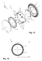
- a second embodiment of the invention is illustrated in the Figures 10 to 17 .
- This second embodiment differs from the first embodiment illustrated on the Figures 1-9 essentially by the general forms of the different elements which constitute them.
- the support 2 has a substantially planar rear wall 3 included in a reference plane P and a single side wall 4 delimiting an interior space 5, the side wall 4 delimiting, on a side opposite to the rear wall 3, a closed circular contour 6 of an opening 7.
- the support 2 then has a section in a plane parallel to the substantially circular reference plane P delimited laterally by a single lateral wall 4.
- the lighting device 1 comprises a lighting system 8 comprising an electric mechanism 9 supplying a plurality of light sources 10 carried by the side wall 4 of the support 2.
- the light sources 10 are oriented towards the interior space 5 and distributed along this circular closed contour 6.
- the light sources 10 are LEDs.
- the set of LEDs are carried by the same side wall 4 and distributed over four printed circuits 16 (PCB) held against this side wall 4 and over the entire closed contour 6 of the interior space 5 by fastening means 17 In this way, all the LEDs are oriented substantially towards the center of the circular shape of the support 2.
- the LEDs are distributed in groups of three LEDs, each group of three LEDs being uniformly distributed around the periphery of the support 2.
- a circuit printed 16 carries three groups of three LEDs each, the lighting device having exactly thirty-six LEDs.
- Collimators 15 in the form of collimating lenses similar to those described in the first embodiment, are arranged next to the LEDs.
- each of these collimators 15 are formed by an elongated piece in the form of a full bar in an arc to match the shape of the curvature of the side wall 4 and each cover one of the groups of three LEDs.
- These collimators 15 are here twelve in number.
- the collimators 15 are clipped onto the printed circuits 16.
- the collimators 15 also make it possible to channel and concentrate the luminous flux towards the reflector 12 without risk of glare.
- a diffuser 11 is arranged to close the opening 7 of the support 2 and adapted to be traversed by the light rays.
- the reflector 12 is located in the interior space delimited by the support 2 and the diffuser 11 to reflect the light rays coming from the light sources towards the diffuser 11.
- the reflector 12 and bordered by another reflector 12 'or peripheral reflector preferably being made of white polycarbonate, polished-mirror or ice-polish or polished aluminum-mirror.
- the presence of this peripheral reflector 12 'in combination with the reflector 12 in the center also allows a more homogeneous visible rendition through the diffuser for a user when the lighting device is off due to the presence of reflective surfaces with the illumination ambient.
- This peripheral reflector 12 ' is here maintained by the diffuser 11 and more precisely by contact with its outer flange.
- the peripheral reflector 12 has substantially a cup shape intended to be housed substantially in the bottom of the interior space 5 of the support 2, that is to say in the vicinity of the rear wall 3, and presents centered in its center a circular opening to inside which the reflector 12 is placed by cooperating with an edge of this circular opening.
- the reflector 12 has in the section defined in the plane of section substantially perpendicular to the reference plane P (see for example figure 14 ) a concave shape oriented on the side of the rear wall 3, and more precisely a flattened dome shape at its upper end 122.
- This concave shape delimits, with the support 2, the chamber 13 inside which the electrical mechanism 9 is housed.
- the reflector 12 completely covers at least the supply circuit 91 disposed substantially in the center of the support 2 and in its interior space 5.
- the concave shape is oriented on the side of the rear wall 3 so that said reflector 12 defines, with this rear wall 3 of the support 2, the chamber 13 inside which the electrical mechanism is housed.
- the reflector does not have a "staircase" configuration.
- the reflector 12 has a concave shape such as a flattened dome where a slope p 121 at its base 121 is always strictly greater than a slope p 122 at its upper end 122, that is to say more inclined relative to the reference plane P.
- the support 2 is circular in shape
- the support 2 as well as the reflector 12 has a shape comprising an axis of symmetry ⁇ , this axis of symmetry ⁇ being defined by an axis of revolution perpendicular to the reference pan P and passing through the center of the circular shape, the assembly of the support 2 and the reflector 12 being such that they are assembled coaxially with respect to this axis of symmetry ⁇ .
- the electric mechanism 9 comprises at least one supply circuit 91 of the lighting system 8 and a control or control circuit 92 of the light sources 10 (not shown in these FIGS. Figures 10-17 ).
- a third embodiment of the invention is illustrated in the Figures 18 to 24 .
- This third embodiment differs from the second embodiment illustrated on the Figures 10-17 essentially in that it further comprises direct lighting sources.
- the lighting system comprises, in addition to light sources 10 carried by the lateral wall 4 of the support 2 forming the indirect lighting, light sources 10 'carried by the rear wall 3 and directed towards the space 5 directly to the diffuser 11, these sources 10 'of light being fed by the same electrical mechanism 9 as that supplying the sources 10 of light forming indirect lighting.
- sources 10 'of light carried by the rear wall 3 are similar to the light sources 10 carried by the side wall 4. Indeed, the sources 10' of the direct lighting are carried by printed circuits 16 'which are maintained fixed against, and intimate contact with the rear wall 3 of the support 2 on the interior space side 5, these sources 10 'of light being light emitting diodes.
- These 10 'light sources are located facing the openings 120' of the peripheral reflector 12 ', these orifices 120' being disposed on a flat portion and parallel to the reference plane P. This portion may optionally have a slight inclination, to know a few degrees.
- the printed circuits 16 ' are here placed directly between the rear wall 3 and a flat portion of the peripheral reflector 12', each orifice 120 'being of oblong shape and placed opposite three LEDs. In addition, each group of three LEDs is carried by the same printed circuit board 16 '.
- the printed circuits 16 ' are interconnected by electronic plies and are arranged substantially in a circle coaxially with respect to the axis of symmetry ⁇ , that is to say that the LEDs of the direct lighting are arranged around of the reflector 12, between said reflector 12 and the side wall 4.
- the oblong orifices 120 ' are uniformly distributed around the reflector 12 in this annular zone and each elongate along tangents to a circle of radius between D 1 and D 2 (preferably closer to D 1 than D 2 to ensure a spacing with the diffuser 11 greater compared to the curved shape of the diffuser), the thirty-six LED light sources 10 'being located substantially along this circle coaxial with the axis of symmetry ⁇ .
- the LEDs have a minimum spacing between them of 10 mm, all of these LEDs providing illumination of 45 x 36 lm (lumen), that is to say 1620 lm, or 1620 cd.sr.
- the diffuser 11 has a curve oriented so as to project substantially with respect to the lighting device 1 increasing the volume of the interior space 5.
- the diffuser is also identical to that illustrated in the second embodiment of the invention. 'invention. This curvature here makes it possible to substantially increase the distance between the diffuser 11 and the sources 10 'of direct lighting without requiring the modification of the dimensions of the support 2 and thus avoid any risk of glare.
- the reflector 12 here exclusively reflects the light rays emitted by the sources 10 carried by the side wall 4, the sources 10 'carried by the rear wall 3 being oriented, and their rays directed, directly towards the diffuser 11.
- an electric mechanism 9 which notably comprises a circuit power supply 91 of the lighting system (see figure 24b and 24c ) and a control circuit or control 92 sources 10, 10 'of light (see figure 24c ).
- the supply circuit 91 comprising a printed circuit 910 carrying the various electronic components, is located entirely under the reflector 12, in the chamber 13.
- the reflector 12 has at its upper end 122 a flat wall parallel to the reference plane P.
- a control or control circuit 92 is here provided, outside the chamber 13, on the reflector 12.
- the reflector must not form a screen blocking the transmission and transmission of the signal.
- the control or control circuit 92 is therefore positioned outside the chamber but remains inside the space delimited by the support 2 and the diffuser 11.
- the curve of the diffuser 11 also offers a greater internal volume 5 important to place said control circuit or control 92 between the upper end 122 of the reflector 12 and said diffuser 11.
- control or control circuit 92 may be positioned partially or totally in the chamber 13.
- the support 2 of the lighting device 1 has at its side walls 4 cooling ribs 18 (see for example figure 17b ) so as to increase the surface dimension of the outer surface in contact with the ambient air so as to also improve the heat exchange.
- These cooling ribs 18 are protruding with respect to the lateral wall 4 from the outside of the support 2, opposite to the interior space 5 of the support.
- These cooling ribs 18 are covered by a ring-shaped circular wall, said circular wall having a cooling function comparable to the cooling ribs 18 and being formed in the same material, here aluminum or Zamac.
- the heat is, on the one hand, discharged by the outer surfaces directly in contact with the outside, and on the other hand, this heat evacuation is favored by the material of the support itself.
- the peripheral reflector 12 has a wall intended to cover it forming locally on the periphery of the lighting device 1 a trim adjacent to the diffuser 11.
- the light-emitting diodes attached to the printed circuits 16, which are in close contact with the support 2, at the inner surface of its side wall 4 also improves this thermal diffusion between the support 2 and the external medium.
- This heat evacuation is similar between the LEDs fixed on printed circuits 16 'in intimate contact with the support 2, at the inner surface of its rear wall 3.
- the closed contour 6 in addition to the illustrated rectangular and circular shapes, may be non-limitatively oval, square, triangular, hexagonal, octagonal, ....
- the overall architecture of the lighting device remains substantially similar to the forms used.
- thermoly conductive heat tab between the printed circuit (s) 16 carrying the light sources 10 and the support 2.
- the lighting device 1 may also comprise additional orientation means of the light rays such as streaks located on the diffuser, or even by the presence of adjustable flaps forming locally reflector wall so that the orientation of the flaps concomitantly or independently from each other allows the control of the orientation of the luminous flux.
- direct lighting can also be provided regardless of the general shape of the lighting device and not only in the case of a lighting device having an axis of symmetry.
- such sources of illumination 10 'could be positioned in a similar manner, for example at the level of orifices situated on a flat portion of the base 121 of the reflector 12.
- stepped configuration of the reflector 12 is only illustrated here in the first embodiment, such a configuration could also be envisaged in the other embodiments and some are the general shapes of the closed contour (circular, oval, triangular, square, hexagonal, ).
- These lighting devices 1 can also be autonomous and include batteries, especially under the reflector namely in the chamber 13, for use in emergency lighting.
Landscapes
- Engineering & Computer Science (AREA)
- General Engineering & Computer Science (AREA)
- Microelectronics & Electronic Packaging (AREA)
- Non-Portable Lighting Devices Or Systems Thereof (AREA)
- Arrangement Of Elements, Cooling, Sealing, Or The Like Of Lighting Devices (AREA)
Abstract
La présente invention concerne un dispositif d'éclairage (1) caractérisé en ce qu'il comprend : un support (2) présentant une paroi arrière (3) sensiblement plane comprise dans un plan de référence (P) et au moins une paroi latérale (4) délimitant un espace intérieur (5), la paroi latérale (4) délimitant, d'un côté opposé à la paroi arrière (3), un contour fermé (6) d'une ouverture (7) ; un système d'éclairage (8) comprenant au moins un mécanisme électrique (9) alimentant une pluralité de sources (10) de lumière portées par la paroi latérale (4) du support (2), orientées vers l'espace intérieur (5) et réparties le long de tout ou partie du contour fermé (6) ; un diffuseur (11) disposé de sorte à fermer l'ouverture (7) du support (2) et adapté pour être traversé par les rayons lumineux ; au moins un réflecteur (12) situé dans l'espace intérieur (5) délimité par le support (2) et le diffuseur (11) pour réfléchir les rayons lumineux issus des sources (10) de lumière vers le diffuseur (11) ; et en ce que le réflecteur (12) délimite, avec le support (2), une chambre (13) à l'intérieur de laquelle est logé le mécanisme électrique (9).The present invention relates to a lighting device (1) characterized in that it comprises: a support (2) having a substantially plane rear wall (3) comprised in a reference plane (P) and at least one side wall ( 4) delimiting an interior space (5), the side wall (4) delimiting, on a side opposite to the rear wall (3), a closed contour (6) of an opening (7); an illumination system (8) comprising at least one electrical mechanism (9) supplying a plurality of light sources (10) carried by the side wall (4) of the support (2) facing the interior space (5) and distributed along all or part of the closed contour (6); a diffuser (11) arranged to close the opening (7) of the support (2) and adapted to be traversed by the light rays; at least one reflector (12) located in the interior space (5) delimited by the support (2) and the diffuser (11) for reflecting the light rays from the sources (10) of light towards the diffuser (11); and in that the reflector (12) delimits, with the support (2), a chamber (13) inside which is housed the electric mechanism (9).
Description
La présente invention concerne un dispositif d'éclairage.The present invention relates to a lighting device.
Des dispositifs d'éclairage, tels que des éclairages d'ambiance pour des locaux publics ou privés tels que des couloirs, ou des éclairages de sécurité, sont bien connus.Lighting devices, such as ambient lighting for public or private premises such as corridors, or security lighting, are well known.
Une problématique rencontrée dans ce type de dispositif d'éclairage est celle de son encombrement. En effet, plus un dispositif est saillant par rapport à une paroi qui le supporte, telle qu'un mur ou un plafond, et plus son volume, aura un effet disgracieux pour un utilisateur. Pour cela, l'une des contraintes de fabrication d'un tel dispositif d'éclairage est que le dispositif soit le plus plat possible de sorte à limiter sa saillie par rapport à la paroi.A problem encountered in this type of lighting device is that of its size. Indeed, plus a device is salient with respect to a wall that supports it, such as a wall or a ceiling, and its volume, will have an unsightly effect for a user. For this, one of the manufacturing constraints of such a lighting device is that the device is as flat as possible so as to limit its projection relative to the wall.
Néanmoins, la diminution de l'encombrement d'un dispositif d'éclairage contraint généralement ces dispositifs à des problèmes d'éblouissement dus à l'éclairage lui-même. En effet, et en particulier lorsque des sources lumineuses sont placées à très faible distance d'une surface d'un diffuseur, il apparait dans ce cas autant de « tâches » lumineuses que de sources lumineuses sur cedit diffuseur qui seront alors visibles par l'utilisateur. En outre, l'intensité lumineuse est dans ce cas trop importante et pourra éblouir son utilisateur.Nevertheless, the reduction in the size of a lighting device generally forces these devices to glare problems due to the lighting itself. Indeed, and in particular when light sources are placed at a very short distance from a surface of a diffuser, it appears in this case as many "tasks" lights that light sources on said diffuser which will then be visible by the user. In addition, the light intensity is in this case too important and may dazzle its user.
Cette problématique est d'autant plus importante lorsque les sources lumineuses du dispositif d'éclairage sont des diodes électroluminescentes (DEL). En effet, dans une telle configuration le nombre de sources lumineuses peut être très important, et donc les tâches présentes seront en grand nombre et amplifiera cet effet disgracieux dû aux tâches tout comme l'intensité lumineuse.This problem is even more important when the light sources of the lighting device are light emitting diodes (LEDs). Indeed, in such a configuration the number of light sources can be very important, and therefore the present tasks will be in large numbers and will amplify this unsightly effect due to tasks as the light intensity.
Par ailleurs, en étant confronté à une telle problématique, il est possible d'éloigner les sources lumineuses du diffuseur. Toutefois, cela aura pour conséquence, d'une part d'augmenter l'encombrement du dispositif d'éclairage et, d'autre part, de diminuer l'intensité du flux lumineux une fois le diffuseur traversé pour éclairer son utilisateur.Furthermore, by being confronted with such a problem, it is possible to move the light sources away from the diffuser. However, this will result, on the one hand to increase the size of the lighting device and, on the other hand, to reduce the intensity of the luminous flux once the diffuser crossed to illuminate the user.
Pour gérer cette problématique d'éblouissement, il est aussi possible d'utiliser une lentille, un réflecteur ou bien encore un diffuseur opalescent.To manage this glare problem, it is also possible to use a lens, a reflector or an opalescent diffuser.
Une lentille permet en effet de concentrer le flux lumineux mais provoque toutefois un fort éblouissement. Il est toujours possible d'éloigner la lentille du diffuseur mais cela n'est faisable qu'au détriment de son encombrement.A lens indeed makes it possible to concentrate the luminous flux but causes however a strong dazzle. It is always possible to remove the lens of the diffuser but this is only feasible to the detriment of its size.
A l'inverse, un réflecteur permet de diminuer l'effet d'éblouissement et de répartir différemment le flux lumineux en sortie du dispositif d'éclairage. Cependant, un réflecteur ne permet pas de canaliser le flux des sources lumineuses, donc son effet est bien moindre.On the contrary, a reflector makes it possible to reduce the glare effect and to distribute the luminous flux differently at the output of the lighting device. However, a reflector does not channel the flow of light sources, so its effect is much less.
Par ailleurs, en jouant sur l'opalescence du diffuseur, il est possible de diminuer l'effet d'éblouissement. Néanmoins, cela diminue également le rendement du dispositif d'éclairage et conduit à l'augmentation de la température dans le produit.Moreover, by playing on the opalescence of the diffuser, it is possible to reduce the glare effect. Nevertheless, this also decreases the efficiency of the lighting device and leads to the increase of the temperature in the product.
Un autre inconvénient lié à ce type de dispositif est celui du mécanisme électrique du dispositif d'éclairage qui rend son encombrement plus important, notamment dans le cas de sources lumineuses de type DEL. En effet, dans le cas des DEL, la problématique du volume est d'autant plus importante qu'un mécanisme électrique alimentant ces DEL est plus volumineux que les mécanismes électriques pour des dispositifs d'éclairage munis d'autres types de sources lumineuses telles que des tubes fluorescents ou des lampes à incandescence qui nécessitent des dispositifs d'alimentation beaucoup moins complexes, voire directement reliés au réseau électrique, ceci pour fournir une luminosité d'intensité sensiblement équivalente.Another disadvantage associated with this type of device is that of the electric mechanism of the lighting device which makes its bulk more important, especially in the case of LED light sources. Indeed, in the case of LEDs, the problem of volume is all the more important as an electrical mechanism supplying these LEDs is larger than the electrical mechanisms for devices lighting with other types of light sources such as fluorescent tubes or incandescent lamps that require much less complex power supply devices, or even directly connected to the power grid, to provide a brightness of substantially equivalent intensity.
Le dispositif décrit par la suite vise à remédier à tout ou partie des inconvénients de l'état de la technique et notamment à réaliser de manière simple et fiable un dispositif d'éclairage, par exemple convivial ou de sécurité, permettant la réduction de son encombrement tout en offrant un flux lumineux assez important pour apporter un éclairage suffisant à un utilisateur et en évitant tout phénomène d'éblouissement.The device described later aims to remedy all or part of the disadvantages of the state of the art and in particular to achieve a simple and reliable lighting device, for example user friendly or security, to reduce its size while providing a luminous flux large enough to provide sufficient lighting for a user and avoiding any phenomenon of glare.
A cet effet, l'invention a pour objet un dispositif d'éclairage comprenant :
- un support présentant une paroi arrière sensiblement plane comprise dans un plan de référence et au moins une paroi latérale délimitant un espace intérieur, la paroi latérale délimitant, d'un côté opposé à la paroi arrière, un contour fermé d'une ouverture ;
- un système d'éclairage comprenant au moins un mécanisme électrique alimentant une pluralité de sources de lumière portées par la paroi latérale du support, orientées vers l'espace intérieur et réparties le long de tout ou partie du contour fermé ;
- un diffuseur disposé de sorte à fermer l'ouverture du support et adapté pour être traversé par les rayons lumineux ; et
- au moins un réflecteur situé dans l'espace intérieur délimité par le support et le diffuseur pour réfléchir les rayons lumineux issus des sources de lumière vers le diffuseur ;
- a support having a substantially flat rear wall in a reference plane and at least one side wall defining an interior space, the side wall defining, on a side opposite the rear wall, a closed contour of an opening;
- a lighting system comprising at least one electrical mechanism supplying a plurality of light sources carried by the lateral wall of the support, oriented towards the interior space and distributed along all or part of the closed contour;
- a diffuser arranged to close the opening of the support and adapted to be traversed by the light rays; and
- at least one reflector located in the interior space delimited by the support and the diffuser for reflecting the light rays from the light sources towards the diffuser;
Le plan de référence correspond de préférence à un plan sensiblement parallèle à celui d'une paroi qui supporte le dispositif, telle qu'un mur ou un plafond.The reference plane preferably corresponds to a plane substantially parallel to that of a wall that supports the device, such as a wall or a ceiling.
Par ailleurs, dans une telle configuration, les sources lumineuses étant disposées latéralement, dirigées vers l'espace intérieur, et les rayons lumineux de ces sources étant réfléchis vers le diffuseur, lequel est placé au niveau de l'ouverture opposée à la paroi arrière, cela permet d'éloigner lesdites sources lumineuses du diffuseur lui-même. Par conséquent tout effet d'éblouissement et de « tâches » lumineuses est supprimé.Moreover, in such a configuration, the light sources being arranged laterally, directed towards the interior space, and the light rays of these sources being reflected towards the diffuser, which is placed at the opening opposite to the rear wall, this makes it possible to move said light sources away from the diffuser itself. Therefore any glare effect and bright "tasks" is removed.
Les rayons lumineux des sources lumineuses portées par les parois latérales étant réfléchis, ces sources lumineuses forment un éclairage indirect et l'éclairement du dispositif d'éclairage est uniforme.The light rays of the light sources carried by the side walls being reflected, these light sources form indirect lighting and the illumination of the lighting device is uniform.
En outre, l'espace intérieur délimité sensiblement par le support et le diffuseur est alors divisé en deux espaces intermédiaires complémentaires par le réflecteur : le premier étant celui à l'intérieur duquel les rayons lumineux des sources lumineuses peuvent évoluer, le second étant celui correspondant à la chambre logeant le mécanisme électrique.In addition, the interior space delimited substantially by the support and the diffuser is then divided into two complementary intermediate spaces by the reflector: the first being the one within which the light rays of the light sources can evolve, the second being that corresponding to the chamber housing the electric mechanism.
Le mécanisme électrique ainsi logé dans la chambre permet un gain d'encombrement qui combiné avec le fait que les sources lumineuses sont disposées sur les parois latérales et non directement derrière le diffuseur, est particulièrement avantageux pour concevoir un dispositif d'éclairage de faible épaisseur. Est entendu ici par le vocable « épaisseur », la distance entre la paroi arrière du support et le diffuseur.The electrical mechanism thus housed in the chamber allows a saving in space, which combined with the fact that the light sources are arranged on the side walls and not directly behind the diffuser, is particularly advantageous for designing a lighting device of small thickness. Is understood here by the term "thickness", the distance between the rear wall of the support and the diffuser.
Avantageusement, la chambre à l'intérieur de laquelle est logé le mécanisme électrique est délimitée sensiblement exclusivement par le réflecteur et le support, de préférence encore par le réflecteur et la paroi arrière du support.Advantageously, the chamber inside which the electrical mechanism is housed is delimited essentially exclusively by the reflector and the support, more preferably by the reflector and the rear wall of the support.
Il est entendu par « sensiblement exclusivement », le fait que la chambre est délimitée par le réflecteur et le support, avec éventuellement certaines pièces de dimensions négligeables par rapport à celle de ladite chambre, pouvant localement former une limite de cette chambre. Cela sera par exemple le cas lorsqu'un joint de faible épaisseur sera disposé entre le réflecteur et le support.It is understood by "substantially exclusively", the fact that the chamber is delimited by the reflector and the support, possibly with some parts of negligible dimensions relative to that of said chamber, which can locally form a limit of this chamber. This will be the case, for example, when a thin seal will be placed between the reflector and the support.
Selon une caractéristique technique particulière, le réflecteur présente une section, dans un plan de coupe sensiblement perpendiculaire au plan de référence, de forme globalement concave orientée du côté de la paroi arrière de sorte que ledit réflecteur délimite, avec ladite paroi arrière du support, la chambre à l'intérieur de laquelle est logé le mécanisme électrique.According to a particular technical characteristic, the reflector has a section, in a plane of section substantially perpendicular to the reference plane, of generally concave shape oriented towards the rear wall side so that said reflector delimits, with said rear wall of the support, the room inside which is housed the electric mechanism.
Une telle configuration, dans laquelle la chambre présente un espace délimité par le réflecteur de forme globalement concave et seulement la paroi arrière du support, c'est-à-dire sans la ou les paroi(s) latérale(s) est particulièrement avantageuse lorsque des sources lumineuses sont disposées sur la ou les paroi(s) latérale(s) opposée(s) dans cette section. De cette manière le volume de la chambre est particulièrement optimisé pour renfermer le mécanisme électrique du dispositif d'éclairage.Such a configuration, in which the chamber has a space delimited by the generally concave shape reflector and only the rear wall of the support, that is to say without the side wall (s) is particularly advantageous when light sources are disposed on the side wall (s) opposite in this section. In this way the volume of the chamber is particularly optimized to enclose the electrical mechanism of the lighting device.
Avantageusement encore, le réflecteur, de forme globalement concave, présente :
- une base inférieure maintenue au support, de préférence au niveau de sa paroi arrière, et située dans une position assemblée au voisinage de la paroi latérale ; et
- une extrémité supérieure disposée, dans la position assemblée, située au voisinage du diffuseur.
- a lower base held to the support, preferably at its rear wall, and located in an assembled position in the vicinity of the side wall; and
- an upper end disposed in the assembled position, located in the vicinity of the diffuser.
Une telle configuration permet à la fois d'améliorer l'intensité lumineuse du dispositif d'éclairage par l'augmentation des surfaces de réflexion tout en optimisant le volume intérieur de la chambre pour y loger le mécanisme électrique.Such a configuration makes it possible at the same time to improve the luminous intensity of the lighting device by increasing the reflection surfaces while optimizing the interior volume of the chamber in order to house the electric mechanism.
Dans une configuration particulière, la base inférieure du réflecteur est maintenue fixe par l'assemblage lui-même des différentes pièces constitutives du dispositif d'éclairage formant moyen de maintien. Dans ce cas, une partie au moins de cette base inférieure peut être prise en « sandwich » lors de l'assemblage de sorte à maintenir le réflecteur contre la paroi arrière. Dans un autre mode de réalisation, la base inférieure est maintenue et fixée au support, notamment à la paroi arrière, par des moyens de fixations, tels que par exemple des pâtes élastiques pour fixer par clipsage la base inférieure du réflecteur à la paroi arrière.In a particular configuration, the lower base of the reflector is held fixed by the assembly itself of the various components of the lighting device forming a holding means. In this case, at least part of this bottom base can be sandwiched during assembly so as to hold the reflector against the rear wall. In another embodiment, the lower base is held and fixed to the support, in particular to the rear wall, by fastening means, such as, for example, elastic pastes for fixing by clipping the lower base of the reflector to the rear wall.
Selon une autre caractéristique avantageuse, la forme globalement concave du réflecteur présente une pente au niveau de sa base strictement supérieure à une pente au niveau de son extrémité supérieure.According to another advantageous characteristic, the overall concave shape of the reflector has a slope at its base strictly greater than a slope at its upper end.
De cette manière, la forme concave présente globalement une forme de dôme, et de préférence encore une forme de dôme aplati.In this way, the concave shape generally has a dome shape, and more preferably a flattened dome shape.
Dans une configuration particulière, le mécanisme électrique comporte au moins un circuit d'alimentation du système d'éclairage et un circuit de contrôle ou de commande des sources de lumière.In a particular configuration, the electrical mechanism comprises at least one power supply circuit of the lighting system and a control circuit for controlling the light sources.
Dans une disposition particulière, le circuit d'alimentation comporte au moins un accumulateur. C'est notamment le cas des dispositifs d'éclairage de sécurité, ceux-ci nécessitant une source auxiliaire d'alimentation en courant électrique.In a particular arrangement, the supply circuit comprises at least one accumulator. This is particularly the case of safety lighting devices, these requiring an auxiliary source of power supply.
Avantageusement encore, le réflecteur présente une section, dans un plan de coupe sensiblement perpendiculaire au plan de référence, qui présente, au moins localement, et successivement :
- des premières portions inclinées de quelques degrés, positivement par rapport au plan de référence et négativement par rapport à la paroi latérale de laquelle proviennent les rayons lumineux qu'elles réfléchissent; et
- des deuxièmes portions inclinées positivement par rapport au plan de référence et négativement par rapport à la paroi latérale de laquelle proviennent les rayons lumineux qu'elles réfléchissent
- first portions inclined a few degrees, positively relative to the reference plane and negatively with respect to the side wall from which the light rays they reflect; and
- second portions inclined positively with respect to the reference plane and negatively with respect to the side wall from which the light rays they reflect
Une telle succession de portions légèrement inclinées et d'inclinaison(s) plus importante(s) permet d'améliorer la réflexion de la lumière sur toute l'étendue du diffuseur tout en évitant le risque de zone d'ombre et en permettant un encombrement minimum, avec un réflecteur présentant une hauteur de sa base à son extrémité supérieure relativement faible.Such a succession of slightly inclined portions and greater inclination (s) (s) improves the reflection of light throughout the diffuser while avoiding the risk of shadows and allowing congestion minimum, with a reflector having a height from its base to its relatively small upper end.
Avantageusement, le dispositif d'éclairage comprend au moins un collimateur pour diriger les rayons lumineux des sources lumineuses vers le réflecteur.Advantageously, the lighting device comprises at least one collimator for directing the light rays of the light sources towards the reflector.
Un tel collimateur permet ainsi de canaliser et de concentrer le flux lumineux, cela sans provoquer d'éblouissement. En effet, de cette manière les rayons lumineux sont tous dirigés vers le réflecteur après avoir été collimatés puis traversent le diffuseur après avoir été réfléchis. Dans une telle configuration, les chemins optiques entre les sources lumineuses portées par la ou les paroi(s) latérale(s) et le diffuseur sont suffisamment importants pour éviter toute apparition de tâche lumineuse, ladite source de lumière n'étant en outre pas directement en regard du diffuseur, et le collimateur permet d'améliorer l'intensité lumineuse.Such a collimator thus allows to channel and concentrate the luminous flux, without causing dazzle. Indeed, in this way the light rays are all directed to the reflector after being collimated and then pass through the diffuser after being reflected. In such a configuration, the optical paths between the light sources carried by the lateral wall (s) (s) and the diffuser are sufficiently important to prevent any appearance of light task, said light source is also not directly in the diffuser, and the collimator makes it possible to improve the luminous intensity.
Par ailleurs, cela ne dégrade en rien l'encombrement du dispositif d'éclairage grâce à la chambre logée intégralement dans l'espace intérieur délimité par le support du dispositif.Furthermore, this does not degrade the overall size of the lighting device thanks to the chamber housed integrally in the interior space delimited by the support of the device.
Avantageusement, le dispositif d'éclairage comprend une pluralité de collimateurs, lesdits collimateurs étant des lentilles collimatrices disposées en regard de chacune des sources de lumière, de préférence en polycarbonate ou en polyméthacrylate de méthyle.Advantageously, the lighting device comprises a plurality of collimators, said collimators being collimating lenses arranged opposite each of the light sources, preferably polycarbonate or polymethylmethacrylate.
Avantageusement encore, les sources de lumière sont des diodes électroluminescentes, de préférence portées par au moins un circuit imprimé lequel est maintenu contre la paroi latérale du support du côté de l'espace intérieur par des moyens de fixation.Advantageously, the light sources are light-emitting diodes, preferably carried by at least one printed circuit which is held against the side wall of the support on the side of the interior space by fixing means.
L'utilisation de diodes électroluminescentes (DEL) peut être permise dans ces conditions sans générer de « tâches » lumineuses, avec une intensité maximale.The use of light-emitting diodes (LEDs) may be permitted under these conditions without generating bright "spots" with maximum intensity.
Dans des configurations particulières, le dispositif d'éclairage comprend des moyens d'orientation supplémentaire des rayons lumineux. Ces moyens d'orientation supplémentaires peuvent par exemple être des stries sur le diffuseur. Dans une configuration alternative ou complémentaire, ces moyens d'orientation peuvent comporter des volets réglables formant localement paroi du réflecteur de sorte que l'orientation des volets de façon concomitantes ou indépendantes les uns des autres permet le contrôle de l'orientation du flux lumineux.In particular configurations, the lighting device comprises means for additional orientation of the light rays. These additional orientation means may for example be streaks on the diffuser. In an alternative or complementary configuration, these orientation means may comprise adjustable flaps forming a local wall of the reflector so that the orientation of the flaps concomitantly or independently of one another allows the control of the orientation of the luminous flux.
De préférence, le support est en aluminium ou en Zamak. Dans d'autres cas, notamment dans le cas de faibles puissances d'éclairage, le support pourra aussi être en matière plastique ou en matière plastique chargée.Preferably, the support is aluminum or Zamak. In other cases, especially in the case of low light levels, the support may also be plastic or plastic loaded.
Cela permet une meilleure évacuation de la chaleur. En effet, pour le bon fonctionnement des diodes électroluminescentes le dispositif d'éclairage est de préférence fermé, et plus précisément étanche, c'est-à-dire hermétiquement fermé. Toutefois dans de telles conditions d'utilisations, la température s'élève rapidement dans l'espace intérieur du support enfermant les sources lumineuses.This allows a better evacuation of the heat. Indeed, for the proper functioning of the light emitting diodes the lighting device is preferably closed, and more precisely sealed, that is to say hermetically closed. However, in such conditions of use, the temperature rises rapidly in the interior space of the support enclosing the light sources.
Dans notre cas, la ou les paroi(s) latérale(s) du support portant les sources lumineuses présentent chacune une surface extérieure, orientée du côté extérieur et une surface intérieure sur laquelle sont fixées tout ou partie des sources lumineuses, lesquelles sont orientées vers l'espace intérieur et réparties le long de tout ou partie du contour fermé.In our case, the lateral wall (s) of the support carrying the light sources each have an outer surface, oriented on the outer side and an inner surface on which are fixed all or part of the light sources, which are directed towards the interior space and distributed along all or part of the closed contour.
Dans cette configuration, d'une part la chaleur est évacuée par les surfaces extérieures directement en contact avec l'extérieur, et d'autre part cette évacuation de chaleur est favorisée par le matériau du support lui-même.In this configuration, on the one hand the heat is removed by the outer surfaces directly in contact with the outside, and on the other hand this heat evacuation is favored by the material of the support itself.
Le support peut aussi présenter, du côté des surfaces extérieures de sa ou ses paroi(s) latérale(s), des nervures de refroidissement de sorte à augmenter la dimension surfacique de la surface extérieure en contact avec l'air ambiant de sorte à améliorer l'échange de chaleur.The support may also have, on the side of the outer surfaces of its or its side wall (s), cooling ribs so as to increase the surface dimension of the outer surface in contact with the ambient air so as to improve heat exchange.
Avantageusement, les diodes électroluminescentes sont fixées sur un circuit, lequel est en contact intime avec le support, au niveau de la ou des surface(s) intérieure(s) de sa ou ses paroi(s) latérales. Un tel contact permet également l'échange de chaleur directement des diodes avec les surfaces extérieures du support.Advantageously, the light-emitting diodes are fixed on a circuit, which is in close contact with the support, at the level of the inner surface (s) of its side wall (s). Such contact also allows heat exchange directly diodes with the outer surfaces of the support.
Avantageusement encore le réflecteur est en polycarbonate blanc, poli-miroir ou poli-glace ou en aluminium poli-miroir, ceci améliorant le pouvoir réfléchissant du réflecteur.Advantageously, the reflector is made of white polycarbonate, mirror-polished or polished-ice or mirror-polished aluminum, this improving the reflecting power of the reflector.
Dans une configuration technique particulière, le diffuseur est en matière plastique opalescente ou transparente.In a particular technical configuration, the diffuser is opalescent plastic or transparent.
Selon une caractéristique avantageuse, le système d'éclairage comprend, en plus des sources de lumière portées par la ou les paroi(s) latérale(s) du support formant l'éclairage indirect, des sources de lumière portées par la paroi arrière et orientées vers l'espace intérieur, de préférence directement vers le diffuseur, ces sources de lumière étant alimentées par le mécanisme électrique.According to an advantageous characteristic, the lighting system comprises, in addition to the light sources carried by the lateral wall (s) of the support forming the indirect lighting, light sources carried by the rear wall and oriented towards the interior space, preferably directly towards the diffuser, these light sources being fed by the electric mechanism.
Dans une telle configuration, les sources de lumière portées par la paroi arrière forment un éclairage direct. En effet, même si une partie minime des rayons provenant de ces sources de lumière peuvent être réfléchis dans l'espace intérieur du dispositif d'éclairage avant de traverser le diffuseur, une grande majorité de leurs rayons lumineux traversent le diffuseur sans réflexion.In such a configuration, the light sources carried by the rear wall form a direct light. Indeed, even if a small portion of the rays from these light sources can be reflected in the interior space of the lighting device before passing through the diffuser, a large majority of their light rays pass through the diffuser without reflection.
De telles sources de lumière formant éclairage direct permettent d'augmenter la puissance du dispositif d'éclairage sans ajouter de sources de lumière portées par la paroi latérale, solution qui nécessiterait alors de modifier les dimensions du support, par exemple en augmentant son diamètre dans le cas d'un contour fermé circulaire. Ceci serait en effet contraire à la problématique d'un faible encombrement.Such direct light sources of light make it possible to increase the power of the lighting device without adding light sources carried by the side wall, a solution which would then necessitate modifying the dimensions of the support, for example by increasing its diameter in the case of a circular closed contour. This would be contrary to the problem of a small footprint.
Par ailleurs, et dans le cas où les sources de lumière sont des diodes électroluminescentes, l'ajout de sources lumineuses formant éclairage direct, portées par la paroi arrière, permet l'utilisation de diodes électroluminescentes moins puissantes pour un éclairage satisfaisant diminuant ainsi le risque d'éblouissement.Moreover, and in the case where the light sources are light-emitting diodes, the addition of direct light sources, carried by the rear wall, allows the use of less powerful light-emitting diodes for a satisfactory lighting thus reducing the risk glare.
Par ailleurs, ces sources d'éclairage direct combinées avec les sources d'éclairage indirect offrent un éclairement maximum au moins compatible avec un niveau normatif d'éclairement de dispositifs munis d'éclairage fluorescent ou incandescent, ceci sans ajouter de points d'éclairages supplémentaires dans la pièce à éclairer.In addition, these direct light sources combined with indirect light sources provide maximum illumination at least compatible with a normative level of illumination of devices with fluorescent or incandescent lighting, without adding additional lighting points. in the room to be illuminated.
Un tel dispositif d'éclairage peut être utilisé bien entendu dans le cadre d'installations neuves, mais surtout dans le cas d'installations existantes, notamment en cas de rénovation, ou le remplacement doit garantir le même niveau normatif d'éclairement que les dispositifs à remplacer.Such a lighting device can be used, of course, in the case of new installations, but especially in the case of existing installations, especially in the case of renovation, or the replacement must guarantee the same normative level of illumination as the devices To replace.
Par ailleurs, dans une telle configuration, l'encombrement du dispositif d'éclairage est similaire à celui du dispositif d'éclairage muni seulement de l'éclairage indirect.Furthermore, in such a configuration, the size of the lighting device is similar to that of the lighting device provided only with indirect lighting.
De préférence, les sources lumineuses portées par la paroi arrière du support sont situées en regard avec des orifices du réflecteur, ces orifices étant situés sur des portions sensiblement planes et parallèle par rapport au plan de référence, et de préférence encore entre ladite paroi arrière et les portions planes du réflecteur les plus proches de cette dite paroi arrière, par exemple au niveau de la base du réflecteur. Ceci garanti un éloignement suffisant de ces sources lumineuses formant éclairage direct du diffuseur évitant tout risque d'éblouissement.Preferably, the light sources carried by the rear wall of the support are located facing reflector orifices, these orifices being located on substantially flat portions and parallel to the reference plane, and more preferably between said rear wall and the planar portions of the reflector closest to said rear wall, for example at the base of the reflector. This guarantees a sufficient distance from these light sources forming direct lighting of the diffuser avoiding any risk of glare.
Avantageusement le diffuseur peut présenter un galbe orienté de sorte à faire sensiblement saillie par rapport au dispositif d'éclairage. En d'autres termes la partie concave du galbe est orientée du côté de l'espace intérieur. Ce galbe permet de contrôler avec précision la distance entre le diffuseur et les sources de lumière de l'éclairage direct sans nécessiter de modifier les dimensions du support, en particulier des parois latérales.Advantageously, the diffuser may have a curve oriented so as to substantially project relative to the lighting device. In other words, the concave part of the curve is oriented towards the interior space. This curve makes it possible to precisely control the distance between the diffuser and the light sources of the direct lighting without requiring to modify the dimensions of the support, in particular the side walls.
Même si le diffuseur présente une forme localement saillante par rapport au support, cette saillie est, en plus d'être localisée, relativement faible par rapport aux dimensions du support, ce dernier n'étant pas modifié. Par conséquent, même si la distance entre la paroi arrière du support et le diffuseur définissant l'épaisseur est localement augmentée, celui-ci ne porte pas préjudice à l'encombrement du dispositif, la ou les paroi(s) latérale(s) présentant une hauteur inchangée. Par ailleurs, dans une certaine mesure ce galbe apporte une esthétique améliorée au dispositif et n'est ici pas de nature à la dégrader.Even if the diffuser has a locally protruding shape relative to the support, this projection is, in addition to being located, relatively low compared to the dimensions of the support, the latter not being modified. Therefore, even if the distance between the rear wall of the support and the diffuser defining the thickness is locally increased, it does not affect the size of the device, the side wall (s) having a height unchanged. Moreover, to a certain extent this curve brings an improved aesthetic to the device and is not likely to degrade it.
De préférence encore, les diodes électroluminescentes sont fixées sur un ou plusieurs circuit(s), lequel est en contact intime avec le support, au niveau de la ou des surface(s) intérieure(s) de sa paroi arrière, ce contact intime permettant l'échange de chaleur directement des diodes de l'éclairage indirect avec les surfaces extérieures du support.More preferably, the light-emitting diodes are fixed on one or more circuit (s), which is in close contact with the support, at the level of the inner surface (s) of its rear wall, this intimate contact allowing heat exchange directly diodes from the indirect lighting with the outer surfaces of the support.
Dans une configuration avantageuse, les sources de lumière portées par la paroi arrière formant éclairage direct sont plus proches du réflecteur que de la paroi latérale du support, ou encore plus proches du réflecteur que de des sources de lumière portées par la paroi latérale du support formant éclairage indirect. Ceci est d'autant plus avantageux lorsque le diffuseur présente un galbe.In an advantageous configuration, the light sources carried by the rear wall forming direct lighting are closer to the reflector than the side wall of the support, or even closer to the reflector than light sources carried by the side wall of the support forming indirect lighting. This is all the more advantageous when the diffuser has a curve.
D'autres caractéristiques et avantages de l'invention ressortiront à la lecture de la description qui suit, donnée uniquement à titre d'exemple, en référence aux figures annexées, qui illustrent :
-
figure 1 , un dispositif d'éclairage selon un premier mode de réalisation ; -
figure 2 , un dispositif d'éclairage selon le premier mode de réalisation et illustré sans son diffuseur ; -
figure 3 , une vue éclatée d'un dispositif d'éclairage selon le premier mode de réalisation ; -
figures 4 et 5 , une vue de face d'un dispositif d'éclairage selon le premier mode de réalisation et une vue en coupe A-A de lafigure 4 ; -
figures 6a et 6b , deux vue en perspective, de dessus et de dessous, d'un réflecteur selon le premier mode de réalisation ; -
figures 7a ,7b et 7c , une vue de face d'un réflecteur selon le premier mode de réalisation et des vues de dessous et de gauche par rapport à cette vue de face ; -
figures 8a, 8b et 8c , deux vues en perspective de dessus et de dessous d'un support d'un dispositif d'éclairage selon le premier mode de réalisation et une vue de face ; -
figures 9a ,9b et 9c , une vue en perspective de dessus d'un support d'un dispositif d'éclairage selon le premier mode de réalisation illustré avec un mécanisme électrique et deux vues en coupe de ce dispositif ; -
figure 10 , un dispositif d'éclairage selon un deuxième mode de réalisation ; -
figure 11 , un dispositif d'éclairage selon le deuxième mode de réalisation et illustré sans son diffuseur ; -
figure 12 , une vue éclatée d'un dispositif d'éclairage selon le deuxième mode de réalisation ; -
figures 13 et 14 , une vue de face d'un dispositif d'éclairage selon le deuxième mode de réalisation et une vue en coupe B-B de lafigure 13 ; -
figures 15a et 15b , deux vue en perspective, de dessus et de dessous, d'un réflecteur selon le deuxième mode de réalisation ; -
figures 16a ,16b et 16c , une vue de face d'un réflecteur selon le deuxième mode de réalisation et des vues de dessous et de gauche par rapport à cette vue de face ; -
figures 17a, 17b et 17c , deux vues en perspective de dessus et de dessous d'un support d'un dispositif d'éclairage selon le deuxième mode de réalisation et une vue de face ; -
figure 18 , une vue éclatée d'un dispositif d'éclairage selon un troisième mode de réalisation -
figures 19a et 19b , des vues de face et en perspective d'un dispositif d'éclairage selon le troisième mode de réalisation et illustré sans son diffuseur ; -
figures 20 et 21 , une vue de face d'un dispositif d'éclairage selon le troisième mode de réalisation et une vue en coupe C-C de lafigure 20 ; -
figures 22a et 22b , deux vues en perspective, de dessus et de dessous, d'un réflecteur selon le troisième mode de réalisation ; -
figures 23 , une vue de face d'un réflecteur selon le troisième mode de réalisation ; -
figures 24a ,24b et 24c , une vue en perspective de dessus d'un support d'un dispositif d'éclairage selon le troisième mode de réalisation illustré notamment avec un mécanisme électrique et sans diffuseur ni réflecteur dans cette vue, et deux vues en coupe de ce dispositif, le diffuseur et le réflecteur étant visibles dans ces deux vues ;
-
figure 1 a lighting device according to a first embodiment; -
figure 2 a lighting device according to the first embodiment and illustrated without its diffuser; -
figure 3 an exploded view of a lighting device according to the first embodiment; -
figures 4 and5 , a front view of a lighting device according to the first embodiment and a sectional view AA of thefigure 4 ; -
Figures 6a and 6b two perspective views, from above and below, of a reflector according to the first embodiment; -
figures 7a ,7b and 7c a front view of a reflector according to the first embodiment and views from below and from the left with respect to this front view; -
Figures 8a, 8b and 8c two perspective views from above and below of a support of a lighting device according to the first embodiment and a front view; -
Figures 9a ,9b and 9c , a perspective view from above of a support of a lighting device according to the first embodiment illustrated with an electric mechanism and two sectional views of this device; -
figure 10 a lighting device according to a second embodiment; -
figure 11 a lighting device according to the second embodiment and illustrated without its diffuser; -
figure 12 an exploded view of a lighting device according to the second embodiment; -
figures 13 and14 , a front view of a lighting device according to the second embodiment and a sectional view BB of thefigure 13 ; -
Figures 15a and 15b two perspective views, from above and from below, of a reflector according to the second embodiment; -
figures 16a ,16b and 16c a front view of a reflector according to the second embodiment and views from below and from the left with respect to this front view; -
Figures 17a, 17b and 17c two perspective views from above and below of a support of a lighting device according to the second embodiment and a front view; -
figure 18 an exploded view of a lighting device according to a third embodiment -
Figures 19a and 19b front and perspective views of a lighting device according to the third embodiment and illustrated without its diffuser; -
Figures 20 and 21 , a front view of a lighting device according to the third embodiment and a sectional view CC of thefigure 20 ; -
Figures 22a and 22b two perspective views, from above and from below, of a reflector according to the third embodiment; -
figures 23 a front view of a reflector according to the third embodiment; -
figures 24a ,24b and 24c a perspective view from above of a support of a lighting device according to the third embodiment illustrated in particular with an electric mechanism and without diffuser or reflector in this view, and two sectional views of this device, the diffuser and the reflector being visible in these two views;
Pour plus de clarté, les éléments identiques ou similaires sont repérés par des signes de référence identiques sur l'ensemble des figures.For the sake of clarity, identical or similar elements are marked with identical reference signs throughout the figures.
Les figures illustrent plusieurs modes de réalisations : les
Le premier mode de réalisation est celui d'un dispositif d'éclairage 1 muni d'un support 2, ledit support 2 présentant une paroi arrière 3 sensiblement plane comprise dans un plan de référence P et quatre parois latérales 4 délimitant un espace intérieur 5, la paroi latérale 4 délimitant, d'un côté opposé à la paroi arrière 3, un contour fermé 6 d'une ouverture 7.The first embodiment is that of a
Dans ce premier mode de réalisation, le support 2 présente une section dans un plan parallèle au plan de référence P sensiblement rectangulaire délimitée par les quatre parois latérales 4.In this first embodiment, the
Le dispositif d'éclairage 1 comprend en outre un système d'éclairage 8 comprenant un mécanisme électrique 9 alimentant une pluralité de sources 10 de lumière lesquelles sont portées par les parois latérales 4 du support 2. Les sources 10 de lumière sont orientées vers l'espace intérieur 5 du support 2 et réparties le long d'une partie seulement du contour fermé 6. En particulier, les sources 10 lumineuses sont réparties sur deux des quatre parois latérales 4, ces deux parois latérales 4 étant les deux parois en vis-à-vis dans le sens de la longueur du support 2.The
La distance séparant les deux parois latérales 4 en vis-à-vis dans le sens de la longueur du support 2, c'est-à-dire longitudinalement, et portant les sources 10 de lumière définit sensiblement la largeur du support 2 et la distance séparant les deux autres parois latérales 4 s'étendant transversalement dans le sens de la largeur, définit la longueur du support 2.The distance separating the two
De façon plus précise, les sources 10 lumineuses sont ici des diodes électroluminescentes (DEL), l'ensemble des DEL portées par une même paroi latérale 4 étant alors portées par un circuit imprimé 16 (PCB) lequel est maintenu contre la paroi latérale 4 en question du côté de l'espace intérieur 5 par des moyens de fixation 17.More precisely, the
Ces moyens de fixations 17 peuvent, d'une manière simple, être formés par l'assemblage des éléments du dispositif d'éclairage 1 entre eux, en particulier par un réflecteur 12 venant, dans cette position assemblée, plaquer le circuit imprimé 16 contre la paroi latérale 4 qui le porte.These fastening means 17 may, in a simple manner, be formed by the assembly of the elements of the
Le support 2 peut être par exemple en aluminium et/ou en Zamak. Ces matériaux offrent une meilleure évacuation de la chaleur générée par les DEL.The
Pour améliorer l'intensité lumineuse tout en évitant tout éblouissement d'un utilisateur, le dispositif d'éclairage 1 est muni de collimateurs 15 de sorte à diriger les rayons lumineux des sources 10 lumineuses vers le réflecteur 12.To improve the luminous intensity while avoiding any dazzling of a user, the
Ces collimateurs 15 sont ici des lentilles collimatrices disposées en regard de chacune des sources 10 lumineuses.These
Dans ce mode de réalisation, les collimateurs 15 sont formés par une pièce allongée en forme de barre, en polycarbonate ou en polyméthacrylate de méthyle. De telles pièces de formes allongées et, ici monoblocs, sont disposées en regard des sources 10 de lumière de sorte à ce chacune d'elles recouvre l'ensemble des DEL portées par une même paroi latérale 4 longitudinale. Est illustrée sur la
De cette manière les collimateurs 15 permettent de canaliser et de concentrer le flux lumineux vers le réflecteur 12, cela sans risque d'éblouissement.In this way the
Par ailleurs, dans cette section transversale, le collimateur est formé par une structure trapézoïdale présentant une grande base et une petite base, la grande base étant accolée du côté de la paroi formant lentille orientée vers l'espace intérieur 5 et la petite base étant située du côté de la DEL, la structure trapézoïdale présentant en outre dans cette section une cavité débouchante au niveau de sa petite base, cavité rectiligne s'étendant perpendiculairement par rapport à la paroi latérale 4 associée.Furthermore, in this cross section, the collimator is formed by a trapezoidal structure having a large base and a small base, the large base being contiguous on the side of the lens wall facing the
Cette cavité présente un fond de forme sensiblement convexe. Cette cavité est en outre dimensionnée de sorte qu'une DEL puisse y pénétrer en tout ou partie, ceci afin d'accoler au plus prêt le collimateur 15 de la paroi latérale 4.This cavity has a bottom of substantially convex shape. This cavity is further dimensioned so that an LED can penetrate all or part of it, so as to bring the
Un diffuseur 11 est disposé de sorte à fermer l'ouverture 7 du support 2 et adapté pour être traversé par les rayons lumineux.A
Le réflecteur 12 est situé dans l'espace intérieur 5 délimité par le support 2 et le diffuseur 11 pour réfléchir les rayons lumineux issus des sources 10 de lumière vers le diffuseur 11.The
Le réflecteur 12 présente dans une section définie dans un plan de coupe perpendiculaire au plan de référence P, une forme concave orientée du côté de la paroi arrière 3.The
Le réflecteur 12 délimite, avec le support 2, une chambre 13 à l'intérieur de laquelle est logé le mécanisme électrique 9. Dans une configuration assemblée, le réflecteur 12 recouvre ledit mécanisme électrique 9 disposé de telle sorte qu'il est sensiblement centré par rapport aux deux parois latérales 4 longitudinales du support 2 dans son espace intérieur 5.The
Dans ce premier mode de réalisation, la forme concave, c'est à dire en d'autres termes la cavité formée par le réflecteur 12, est orientée du côté de la paroi arrière 3 de sorte que ledit réflecteur 12 délimite, avec cette paroi arrière 3 du support 2, la chambre 13 à l'intérieur de laquelle est logé le mécanisme électrique 9.In this first embodiment, the concave shape, that is to say in other words the cavity formed by the
De manière plus précise, le réflecteur 12, de forme globalement concave, présente :
une base 121 inférieure maintenue fixe ausupport 2, de préférence àsa paroi arrière 3,ladite base 121 étant située, dans une position assemblée, au voisinage des deux parois latérales 4 longitudinales portant lessources 10 lumineuses ; etune extrémité 122 supérieure disposée, dans la position assemblée, au voisinage du diffuseur 11.
- a
lower base 121 held fixed to thesupport 2, preferably to itsrear wall 3, saidbase 121 being located, in an assembled position, in the vicinity of the twolongitudinal side walls 4 carrying thelight sources 10; and - an
upper end 122 disposed in the assembled position in the vicinity of thediffuser 11.
Dans la configuration illustrée notamment
De cette manière, et dans cette vue en coupe, la forme concave du réflecteur 12 présente globalement une forme de dôme aplati.In this way, and in this sectional view, the concave shape of the
Les portions en « escaliers » permettent, à l'inverse d'une courbe lissée, d'améliorer le volume utile de la chambre 13 à l'intérieur de laquelle est logé le mécanisme électrique 9. Est entendu par le vocable « volume utile » le volume exploitable pour y loger ledit mécanisme électrique 9. En effet, bien qu'un espace d'un certain volume soit délimité par la chambre 13, la totalité de ce volume n'est pas exploitable. La disposition en « escalier » permet, à volume total constant, de former un volume utile plus important facilitant la mise en place de mécanisme électrique 9 tout en garantissant une configuration améliorée pour assurer sa fonction de réflexion.The portions "stairs" allow, unlike a smooth curve, to improve the useful volume of the
En particulier, cette forme en « escalier » est obtenue du fait que le réflecteur 12 présente dans cette même section, perpendiculaire au plan de référence P :
- des premières portions légèrement ou faiblement inclinées 123 par rapport au plan de référence P, c'est à dire inclinées de quelques degrés, cette inclinaison étant positive d'un angle a' par rapport au plan de référence P et négative d'un angle β' par rapport à la paroi latérale 4 de laquelle proviennent les rayons lumineux qu'elles réfléchissent ; et
- des deuxièmes
portions inclinées 124 positivement d'un angle α par rapport au plan de référence P et négativement d'un angle β par rapport à la paroi latérale 4 de laquelle proviennent les rayons lumineux qu'elles réfléchissent (voir en particulierfigure 5 ).
- first portions slightly or slightly inclined 123 relative to the reference plane P, that is to say inclined by a few degrees, this inclination being positive by an angle a 'with respect to the reference plane P and negative by an angle β with respect to the
lateral wall 4 from which the light rays which they reflect originate; and - second
inclined portions 124 positively at an angle α with respect to the reference plane P and negatively at an angle β with respect to theside wall 4 from which the light rays which they reflect (see in particularfigure 5 ).
En particulier, les premières portions 123 ne sont pas parallèles au plan de référence P, cette légère inclinaison permettant de refléter un minimum de lumière afin de ne pas créer de zone sombre, ou moins lumineuse, sur la surface du réflecteur 12, de telles zones sombres étant visibles sur le réflecteur 12 si α' est inférieur ou égale à 0. Cela se traduit par une inclinaison α' des premières portions 123 qui est :
- strictement positive (c'est-à-dire α'>0) ; et
- strictement inférieure à l'inclinaison α des deuxièmes portions inclinées 124 (c'est-à-dire α'< α);
ceci par rapport au plan de référence P. Ainsi on comprendra par le vocable « faiblement inclinées » relatif au premièresportions 123 le fait qu'elles sont inclinées de quelques degrés et moins inclinées que les deuxièmes portions inclinées 124. Par le vocable « quelques degrés » est entendu moins de 10 degrés, de préférence entre 0.5 et 5 degrés.
- strictly positive (that is, α '>0); and
- strictly lower than the inclination α of the second inclined portions 124 (that is to say α '<α);
this with respect to the reference plane P. Thus it will be understood by the term "slightly inclined" relative to thefirst portions 123 the fact that they are inclined by a few degrees and less inclined than the secondinclined portions 124. By the term "a few degrees Is understood to be less than 10 degrees, preferably between 0.5 and 5 degrees.
Dans notre cas la somme des valeurs des angles α et β, comme celle des angles α' et β', est égale à 90 degrés du fait que les parois latérales 4 sont dressées perpendiculairement à la paroi arrière 3. De préférence, ces deuxièmes portions inclinées 124 présentent une inclinaison d'un angle α compris entre 20 et 70 degrés par rapport au plan de référence P et de préférence encore comprise entre 40 et 50 degrés. Dans ce mode de réalisations les valeurs des angles α et β sont toutes deux égales à 45 degrés, en valeur absolue.In our case, the sum of the values of the angles α and β, such as that of the angles α 'and β', is equal to 90 degrees because the
Par ailleurs, et de sorte à ce que la forme concave présente une forme de dôme aplati :
- plus les premières portions faiblement inclinées 123 sont proches de la
base 121, c'est-à-dire aussi éloignées de l'extrémité 122 supérieure, et plus leur longueur est petite ; et - plus les deuxièmes portions inclinées 124 sont proches de la
base 121, c'est-à-dire aussi éloignées de l'extrémité 122 supérieure, et plus leur longueur est grande ; et
- more the first slightly
inclined portions 123 are close to thebase 121, that is to say as far from theupper end 122, and their length is smaller; and - more the second
inclined portions 124 are close to thebase 121, that is to say, as far away from theupper end 122, and their length is greater; and
Le support 2 étant de forme rectangulaire, le réflecteur 12 présente une forme présentant un plan de symétrie, ce plan de symétrie étant défini par un plan perpendiculaire au pan de référence P et passant par son extrémité 122.The
La section illustrée
Par ailleurs, le mécanisme électrique 9 comporte au moins un circuit d'alimentation 91 du système d'éclairage 8 et un circuit de contrôle ou de commande 92 des sources 10 de lumière.Moreover, the
Quelque soit le mode de réalisation, le circuit d'alimentation 91 est logé dans la chambre 13. Toutefois, dans certaines configurations particulières certaines contraintes de fonctionnement peuvent imposer de placer le circuit de contrôle ou de commande 92 en tout ou partie à l'extérieur de cette chambre 13.Whatever the embodiment, the
Un circuit de contrôle ou de commande 92 peut être formé par un ou plusieurs circuit(s) sous forme de bloc(s) annexe(s), ceci afin d'assurer une ou plusieurs fonction(s) de contrôle ou de commande particulière(s) selon l'utilisation du dispositif d'éclairage 1.A control or
Par exemple, un circuit de contrôle ou de commande 92 peut comporter un circuit, annexe au circuit d'alimentation 91, permettant d'actionner l'allumage, ou la mise sous tension, des sources 10 lumineuses lorsque la présence d'un utilisateur est détectée. Le circuit de contrôle ou de commande 92 peut aussi comporter, en complément ou de façon alternative, un circuit permettant l'allumage des sources 10 lumineuses lorsque la luminosité ambiante diminue en-deçà d'une valeur seuil prédéterminée.For example, a control or
Sont en particulier illustrés (voir
Le circuit de contrôle ou de commande 92 est ici situé dans une deuxième zone Z2 de l'espace intérieur 5 du support 2, opposée à la première zone Z1. Ce circuit de contrôle ou de commande 92 comprend ici deux circuits imprimés reliés électriquement l'un à l'autre, un détecteur haute fréquence 921 étant fixé à l'un de ces circuits imprimés et un dispositif d'émission/réception infrarouge 922 étant disposé sur l'autre 920 de ces circuits imprimés.The control or
Le dispositif d'émission/réception infrarouge 922 est placé de sorte à être au voisinage de la paroi latérale 4 formant largeur du support 2, c'est-à-dire ne portant pas de source 10 lumineuse, et de sorte à être placé au voisinage de l'extrémité 122 supérieure du réflecteur 12 disposée, dans la position assemblée, au voisinage du diffuseur 11.The infrared transmitting /
En regard de ce dispositif d'émission/réception infrarouge 922 et entre ce dernier et le diffuseur 11 est placée une partie du réflecteur 12. Localement à cet endroit des rayons infrarouges du dispositif d'émission/réception infrarouge 922 doivent pouvoir circuler. Dans ce mode de réalisation, et localement au niveau de ce dispositif d'émission/réception infrarouge 922, le réflecteur 12 présente une partie transparente voir translucide de sorte à assurer le bon fonctionnement du dispositif. Alternativement, le réflecteur 12 peut présenter localement au niveau de ce dispositif d'émission/réception infrarouge 922 un jour, c'est-à-dire qu'il n'y a pas de matière entre ledit dispositif d'émission/réception infrarouge 922 et le diffuseur.Opposite this infrared transmitting /
Un bloc connectique sépare, dans l'espace intérieur 5, les première et deuxième zones Z1, Z2 l'une de l'autre. Ce bloc présente ici au niveau d'une paroi supérieure des butée sur lesquelles le réflecteur 12 vient en appui au niveau de son extrémité 122 supérieure, du côté de la chambre 13 et en position assemblée, de sorte à assurer la bonne mise en place du réflecteur 12 dans l'espace intérieur 5 du support 2.A connector block separates, in the
Un tel circuit de contrôle ou de commande 92 permet d'actionner l'allumage, ou la mise sous tension, des sources 10 lumineuses lorsque dispositif d'émission/réception infrarouge 922 détecte la présence d'un utilisateur.Such a control or
De part sa configuration, et durant son fonctionnement, les rayons lumineux émis par une DEL sont canalisés par la lentille collimatrice 15 située au plus prés de ces DEL. Tous les rayons sont maitrisés et ils sont tous envoyés sur une portion inclinée 123, 124 du réflecteur 12. Aucun rayon ne sort de l'espace intérieur 5 du support 2 sans avoir été réfléchit sur au moins une paroi du réflecteur 12. Les rayons lumineux sont envoyés le plus perpendiculairement possible sur le diffuseur 11 par rapport au plan de référence P ce qui permet d'atténuer le risque d'éblouissement. Les rayons traversent ensuite le diffuseur 11 opalescent, ou transparent selon le rendu et le rendement souhaité, sans forme particulière pour ne pas modifier à nouveau l'intensité lumineuse des rayons. Par ce biais, il est ainsi possible de maitriser l'éclairement et l'éblouissement des DEL dans un produit d'épaisseur réduite.Due to its configuration, and during its operation, the light rays emitted by an LED are channeled by the
Le support 2 présente en outre au niveau de ses parois latérales 4 faisant saillies du côté extérieur au support, des nervures de refroidissement 18 (voir par exemple
Un deuxième mode de réalisation de l'invention est illustré dans les
Ce deuxième mode de réalisation diffère du premier mode de réalisation illustré sur les
En particulier dans ce deuxième mode de réalisation, le support 2 présente une paroi arrière 3 sensiblement plane comprise dans un plan de référence P et une seule paroi latérale 4 délimitant un espace intérieur 5, la paroi latérale 4 délimitant, d'un côté opposé à la paroi arrière 3, un contour fermé 6 circulaire d'une ouverture 7. Le support 2 présente alors une section dans un plan parallèle au plan de référence P sensiblement circulaire délimitée latéralement par une unique paroi latérale 4.In particular in this second embodiment, the
Comme dans le premier mode de réalisation, le dispositif d'éclairage 1 comprend un système d'éclairage 8 comprenant un mécanisme électrique 9 alimentant une pluralité de sources 10 de lumière portées par la paroi latérale 4 du support 2. Les sources 10 de lumière sont orientées vers l'espace intérieur 5 et réparties le long de ce contour fermé 6 circulaire. En particulier, les sources 10 lumineuses sont des DEL.As in the first embodiment, the
L'ensemble des DEL sont portées par la même paroi latérale 4 et réparties sur quatre circuits imprimés 16 (PCB) maintenus contre cette paroi latérale 4 et sur tout le contour fermé 6 du côté de l'espace intérieur 5 par des moyens de fixation 17. De cette manière toutes les DEL sont orientées sensiblement vers le centre de la forme circulaire du support 2. Les DEL sont réparties par groupement de trois DEL, chaque groupement de trois DEL étant uniformément répartis sur le pourtour du support 2. Ici, un circuit imprimé 16 porte trois groupements de trois DEL chacun, le dispositif d'éclairage comportant exactement trente-six DEL.The set of LEDs are carried by the
Des collimateurs 15, sous forme de lentilles collimatrices semblables à celles décrites dans le premier mode de réalisation, sont disposés en regard des DEL. En particulier, chacun de ces collimateurs 15 sont formés par une pièce allongée en forme de barre pleine en arc de cercle pour épouser la forme de la courbure de la paroi latérale 4 et recouvrent chacun un des groupements de trois DEL. Ces collimateurs 15 sont ici au nombre de douze. Les collimateurs 15 sont fixés par clipsage sur les circuits imprimés 16.
De cette manière les collimateurs 15 permettent également de canaliser et de concentrer le flux lumineux vers le réflecteur 12 sans risque d'éblouissement.In this way, the
Un diffuseur 11 est disposé de sorte à fermer l'ouverture 7 du support 2 et adapté pour être traversé par les rayons lumineux.A
Le réflecteur 12 est situé dans l'espace intérieur 5 délimité par le support 2 et le diffuseur 11 pour réfléchir les rayons lumineux issus des sources 10 de lumière vers le diffuseur 11.The
Dans ce deuxième mode de réalisation, le réflecteur 12 et bordé par un autre réflecteur 12' ou réflecteur périphérique, ce dernier étant de préférence en polycarbonate blanc, poli-miroir ou poli-glace ou en aluminium poli-miroir. La présence de ce réflecteur périphérique 12' en combinaison avec le réflecteur 12 au centre permet aussi un rendu visible plus homogène à travers le diffuseur pour un utilisateur lorsque le dispositif d'éclairage est éteint du fait de la présence de surfaces réfléchissantes avec l'éclairage ambiant.In this second embodiment, the
Ce réflecteur périphérique 12' est ici maintenu par le diffuseur 11 et plus précisément par contact avec sa collerette extérieure.This peripheral reflector 12 'is here maintained by the
En effet, le réflecteur périphérique 12' présente sensiblement une forme de coupelle destinée à venir se logée sensiblement dans le fond de l'espace intérieur 5 du support 2, c'est-à-dire au voisinage de la paroi arrière 3, et présente centrée en son centre une ouverture circulaire à l'intérieur de laquelle le réflecteur 12 vient se placer en coopérant avec un bord de cette ouverture circulaire.Indeed, the peripheral reflector 12 'has substantially a cup shape intended to be housed substantially in the bottom of the
Par ailleurs, le réflecteur 12 présente une forme globalement concave comprenant :
une base 121 inférieure maintenue fixe par l'assemblage du dispositif d'éclairage 1, en particulier en étant plaqué par le réflecteur périphérique 12' contre la paroi arrière 3, ceci formant moyen de maintien 14 ; etune extrémité 122 supérieure disposée, dans la position assemblée, située au voisinage du diffuseur 11.
- a
lower base 121 held fixed by the assembly of thelighting device 1, in particular by being plated by the peripheral reflector 12 'against therear wall 3, this forming holding means 14; and - an
upper end 122 arranged, in the assembled position, located in the vicinity of thediffuser 11.
Le réflecteur 12 présente dans la section définie dans le plan de coupe sensiblement perpendiculaire au plan de référence P (voir par exemple
Cette forme concave délimite, avec le support 2, la chambre 13 à l'intérieur de laquelle est logé le mécanisme électrique 9. Dans une configuration assemblée, le réflecteur 12 recouvre intégralement au moins le circuit d'alimentation 91 disposé sensiblement au centre du support 2 et dans son espace intérieur 5.This concave shape delimits, with the
Dans ce deuxième mode de réalisation, la forme concave est orientée du côté de la paroi arrière 3 de sorte que ledit réflecteur 12 délimite, avec cette paroi arrière 3 du support 2, la chambre 13 à l'intérieur de laquelle est logé le mécanisme électrique 9.In this second embodiment, the concave shape is oriented on the side of the
Contrairement au premier mode de réalisation, dans le deuxième mode de réalisation, le réflecteur ne présente par de configuration en « escalier ». En effet, ici le réflecteur 12 présente une forme concave telle un dôme aplati où une pente p121 au niveau de sa base 121 est toujours strictement supérieure à une pente p122 au niveau de son extrémité supérieure 122, c'est-à-dire plus inclinée par rapport au plan de référence P.In contrast to the first embodiment, in the second embodiment, the reflector does not have a "staircase" configuration. Indeed, here the
Le support 2 étant de forme circulaire, le support 2 ainsi que réflecteur 12 présente une forme comprenant un axe de symétrie Δ, cet axe de symétrie Δ étant défini par un axe de révolution perpendiculaire au pan de référence P et passant par le centre de la forme circulaire, l'assemblage du support 2 et du réflecteur 12 étant tel qu'ils sont assemblés coaxialement par rapport à cet axe de symétrie Δ.Since the
Par ailleurs, le mécanisme électrique 9 comporte au moins un circuit d'alimentation 91 du système d'éclairage 8 et un circuit de contrôle ou de commande 92 des sources 10 de lumière (non illustré sur ces
Un troisième mode de réalisation de l'invention est illustré dans les
Ce troisième mode de réalisation diffère du deuxième mode de réalisation illustré sur les
En effet, le système d'éclairage comprend, en plus des sources 10 de lumière portées par la paroi latérale 4 du support 2 formant l'éclairage indirect, des sources 10' de lumière portées par la paroi arrière 3 et orientées vers l'espace intérieur 5 directement vers le diffuseur 11, ces sources 10' de lumière étant alimentées par le même mécanisme électrique 9 que celui alimentant les sources 10 de lumière formant éclairage indirect.Indeed, the lighting system comprises, in addition to
Ces autres sources 10' de lumière portées par la paroi arrière 3 sont similaires aux sources 10 de lumière portées par la paroi latérale 4. En effet, les sources 10' de l'éclairage direct sont portées par des circuits imprimés 16' lesquels sont maintenus fixes contre, et en contact intime avec, la paroi arrière 3 du support 2 du côté de l'espace intérieur 5, ces sources 10' de lumière étant des diodes électroluminescentes.These
Ces sources 10' lumineuses sont situées en regard avec des orifices 120' du réflecteur périphérique 12', ces orifices 120' étant disposés sur une portion plane et parallèle par rapport au plan de référence P. Cette portion peut présenter éventuellement une légère inclinaison, à savoir de quelques degrés.These 10 'light sources are located facing the
Les circuits imprimés 16' sont ici placés directement entre la paroi arrière 3 et une portion plane du réflecteur périphérique 12', chaque orifice 120' étant de forme oblongue et placé en regard de trois DEL. En outre, chaque groupement de trois DEL est porté par un même circuit imprimé 16'.The printed circuits 16 'are here placed directly between the
Les circuits imprimés 16' sont reliés entre eux par des nappes électroniques et sont disposés sensiblement suivant un cercle coaxialement par rapport à l'axe de symétrie Δ, c'est-à-dire encore que les DEL de l'éclairage direct sont disposées autour du réflecteur 12, entre ledit réflecteur 12 et la paroi latérale 4.The printed circuits 16 'are interconnected by electronic plies and are arranged substantially in a circle coaxially with respect to the axis of symmetry Δ, that is to say that the LEDs of the direct lighting are arranged around of the
L'idéal en effet est que ces sources 10' de lumière soient disposées de telle sorte que leur espacement avec le diffuseur 11 soit le plus grand, c'est-à-dire ici le plus prêt du centre (traversé par l'axe de symétrie Δ). Cette zone sensiblement annulaire entre le réflecteur et la paroi latérale 4 permet ainsi un emplacement des LED avantageux pour obtenir un rendu sans point visible par l'utilisateur, le dispositif d'éclairage 1 conservant ainsi son aspect visuel uniforme sur l'ensemble de la surface du diffuseur lorsque ledit dispositif d'éclairage 1 est allumé.The ideal in fact is that these
D'une manière plus précise, cette zone annulaire correspond ici à une zone sensiblement délimitée par (voir
- un diamètre intérieure D1, égale à 136 mm, correspondant sensiblement au diamètre extérieur du réflecteur 12 et ;
- un diamètre extérieur D2, égale à 200 mm, correspondant sensiblement au diamètre intérieur de la forme cylindrique formé par la paroi latérale 4 auquel a été retranché deux fois l'épaisseur d'une lentille collimatrice 15 dirigeant les rayons lumineux des
sources 10 lumineuses vers le réflecteur 12.
- an inner diameter D 1 , equal to 136 mm, substantially corresponding to the outer diameter of the
reflector 12 and; - an outer diameter D 2 , equal to 200 mm, substantially corresponding to the internal diameter of the cylindrical shape formed by the
side wall 4 to which twice the thickness of acollimating lens 15 has been directed, directing the light rays from the light sources towards thereflector 12.
Les orifices 120' oblongs sont répartis uniformément autour du réflecteur 12 dans cette zone annulaire et s'allongent chacun suivant des tangentes à un cercle de rayon compris entre D1 et D2 (de préférence plus proche de D1 que de D2 pour assurer un espacement avec le diffuseur 11 plus grand au regard de la forme galbée du diffuseur), les trente-six DEL des sources 10' de lumière étant situées sensiblement suivant ce cercle coaxial à l'axe de symétrie Δ. Les LED présentent un espacement minimum entre elles de 10 mm, l'ensemble de ces LED offrant un éclairage de 45 x 36 lm (lumen), c'est-à-dire 1620 lm, soit 1620 cd.sr.The
Par ailleurs, le diffuseur 11 présente un galbe orienté de sorte à faire sensiblement saillie par rapport au dispositif d'éclairage 1 augmentant le volume de l'espace intérieur 5. Le diffuseur est également identique à celui illustré dans le deuxième mode de réalisation de l'invention. Ce galbe permet ici d'augmenter sensiblement la distance entre le diffuseur 11 et les sources 10' de lumière de l'éclairage direct sans nécessiter de modifier les dimensions du support 2 et ainsi éviter tout risque d'éblouissement.Furthermore, the
Le réflecteur 12 reflète ici exclusivement les rayons lumineux émis par les sources 10 portées par la paroi latérale 4, les sources 10' portées par la paroi arrière 3 étant orientées, et leurs rayons dirigés, directement vers le diffuseur 11.The
Sont visibles notamment dans les
Le circuit d'alimentation 91, comprenant un circuit imprimé 910 portant les différents composants électroniques, est situé intégralement sous le réflecteur 12, dans la chambre 13.The
Par ailleurs le réflecteur 12 présente ici au niveau de son extrémité 122 supérieure une paroi plane parallèle au plan de référence P. Un circuit de contrôle ou de commande 92 est ici prévu, hors de la chambre 13, sur le réflecteur 12.Furthermore, the
En effet, pour pouvoir assurer une fonction de détection du circuit de contrôle ou de commande 92, le réflecteur ne doit pas former un écran bloquant l'émission et la transmission du signal. Le circuit de contrôle ou de commande 92 est donc positionné à l'extérieur de la chambre mais reste à l'intérieur de l'espace délimité par le support 2 et le diffuseur 11. Le galbe du diffuseur 11 offre également un volume intérieur 5 plus important permettant d'y placer ledit circuit de contrôle ou de commande 92 entre l'extrémité 122 supérieure du réflecteur 12 et ledit diffuseur 11.Indeed, to be able to provide a detection function of the control or
Une solution alternative est de configurer la paroi plane située au niveau de l'extrémité 122 supérieure du réflecteur 12 de sorte à ce qu'elle soit au moins localement ouverte, transparente, ou au moins translucide. Dans une telle configuration le circuit de contrôle ou de commande 92 peut être positionné en partie ou en totalité dans la chambre 13.An alternative solution is to configure the flat wall located at the
Par ailleurs, le support 2 du dispositif d'éclairage 1 présente au niveau de ses parois latérales 4 des nervures de refroidissement 18 (voir par exemple
Dans cette configuration, la chaleur est, d'une part, évacuée par les surfaces extérieures directement en contact avec l'extérieur, et d'autre part, cette évacuation de chaleur est favorisée par le matériau du support lui-même.In this configuration, the heat is, on the one hand, discharged by the outer surfaces directly in contact with the outside, and on the other hand, this heat evacuation is favored by the material of the support itself.
Le réflecteur périphérique 12' présente une paroi destinée à venir la recouvrir formant localement sur la périphérie du dispositif d'éclairage 1 un enjoliveur bordant le diffuseur 11.The peripheral reflector 12 'has a wall intended to cover it forming locally on the periphery of the lighting device 1 a trim adjacent to the
Les diodes électroluminescentes fixées sur les circuits imprimés 16, lesquels sont en contact intime avec le support 2, au niveau de la surface intérieure de sa paroi latérale 4 améliore également cette diffusion thermique entre le support 2 et le milieu extérieur. Cette évacuation de chaleur est similaire entre ce qui concerne les DEL fixées sur les circuits imprimés 16' en contact intime avec le support 2, au niveau de la surface intérieure de sa paroi arrière 3.The light-emitting diodes attached to the printed
De façon générale, d'autres modes de réalisation peuvent être envisagés, notamment par leurs formes. En particulier, le contour fermé 6, outre les formes rectangulaires et circulaires illustrés, peut être de façon non limitative ovale, carré, triangulaire, hexagonale, octogonale, .... L'architecture globale du dispositif d'éclairage reste sensiblement similaire outre les formes employées.In general, other embodiments can be envisaged, in particular by their shapes. In particular, the
Par ailleurs, il peut être envisagé l'utilisation d'une patte thermique conductrice de chaleur entre le ou les circuits imprimé(s) 16 portant les sources 10 de lumière et le support 2.Furthermore, it can be envisaged the use of a thermally conductive heat tab between the printed circuit (s) 16 carrying the
Le dispositif d'éclairage 1 peut également comprendre des moyens d'orientation supplémentaire des rayons lumineux tels que des stries situées sur le diffuseur, ou bien encore par la présence de volets réglables formant localement paroi du réflecteur de sorte que l'orientation des volets de façon concomitantes ou indépendantes les uns des autres permet le contrôle de l'orientation du flux lumineux.The
Par ailleurs, la possibilité d'un éclairage direct peut également être prévu quelque soit la forme générale du dispositif d'éclairage et pas seulement dans le cas d'un dispositif d'éclairage présentant un axe de symétrie. Par exemple dans le cas du première mode de réalisation, de telles sources 10' d'éclairage pourraient être positionnées de manière similaire par exemple au niveau d'orifices situés sur une portion plane de la base 121 du réflecteur 12.Moreover, the possibility of direct lighting can also be provided regardless of the general shape of the lighting device and not only in the case of a lighting device having an axis of symmetry. For example, in the case of the first embodiment, such sources of
Bien qu'une configuration dite « en escalier » du réflecteur 12 ne soit ici illustrée que dans le premier mode de réalisation, une telle configuration pourrait également être envisagée dans les autres modes de réalisation et quelques soient les formes générales du contour fermé (circulaire, ovale, triangulaire, carré, hexagonale, ...).Although a "stepped" configuration of the
Ces dispositifs d'éclairage 1 peuvent aussi être autonomes et comporter des batteries, notamment sous le réflecteur à savoir dans la chambre 13, afin d'être utilisé en éclairage de secours.These
L'invention est décrite dans ce qui précède à titre d'exemple. Il est entendu que l'homme du métier est à même de réaliser différentes variantes de réalisation de l'invention sans pour autant sortir du cadre de l'invention.The invention is described in the foregoing by way of example. It is understood that the skilled person is able to achieve different embodiments of the invention without departing from the scope of the invention.
Claims (13)
caractérisé en ce que la forme globalement concave du réflecteur (12) présente une pente (p121) au niveau de sa base (121) strictement supérieure à une pente (p122) au niveau de son extrémité supérieure (122).
characterized in that the generally concave shape of the reflector (12) has a slope (p 121 ) at its base (121) strictly greater than a slope (p 122 ) at its upper end (122).
les deuxièmes portions inclinées (124) présentant une inclinaison strictement supérieure à l'inclinaison des premières portions inclinées (123).
the second inclined portions (124) having an inclination strictly greater than the inclination of the first inclined portions (123).
Applications Claiming Priority (1)
| Application Number | Priority Date | Filing Date | Title |
|---|---|---|---|
| FR1362776A FR3015002B1 (en) | 2013-12-17 | 2013-12-17 | LIGHTING DEVICE |
Publications (1)
| Publication Number | Publication Date |
|---|---|
| EP2886942A1 true EP2886942A1 (en) | 2015-06-24 |
Family
ID=50473457
Family Applications (1)
| Application Number | Title | Priority Date | Filing Date |
|---|---|---|---|
| EP14197788.4A Withdrawn EP2886942A1 (en) | 2013-12-17 | 2014-12-12 | Lighting device |
Country Status (3)
| Country | Link |
|---|---|
| EP (1) | EP2886942A1 (en) |
| CN (1) | CN104713012A (en) |
| FR (1) | FR3015002B1 (en) |
Cited By (4)
| Publication number | Priority date | Publication date | Assignee | Title |
|---|---|---|---|---|
| EP3220042A1 (en) * | 2016-03-14 | 2017-09-20 | Tridonic Jennersdorf GmbH | Luminaire with motion detection means |
| IT201900005194A1 (en) * | 2019-04-05 | 2020-10-05 | Ares S R L Socio Unico | ASSEMBLY OF LIGHTING |
| FR3100307A1 (en) * | 2019-08-27 | 2021-03-05 | Ilia Potemine | Removable lighting device, set of such devices and corresponding lighting installation |
| IT202000013903A1 (en) * | 2020-06-10 | 2021-12-10 | Ares S R L Socio Unico | ASSEMBLY OF LIGHTING |
Families Citing this family (3)
| Publication number | Priority date | Publication date | Assignee | Title |
|---|---|---|---|---|
| US10627096B2 (en) * | 2015-11-26 | 2020-04-21 | Signify Holding B.V. | Lighting device |
| CN112963745B (en) * | 2016-02-15 | 2023-09-29 | 莫列斯有限公司 | Lighting device |
| US11306886B2 (en) * | 2019-03-20 | 2022-04-19 | Hubbell Lighting, Inc. | Light fixture |
Citations (11)
| Publication number | Priority date | Publication date | Assignee | Title |
|---|---|---|---|---|
| JP2009117346A (en) * | 2007-10-16 | 2009-05-28 | Momo Alliance Co Ltd | Illuminating device |
| US20090290348A1 (en) * | 2006-04-16 | 2009-11-26 | Peter Van Laanen | Thermal Management Of LED-Based Lighting Systems |
| US20100079087A1 (en) * | 2008-09-30 | 2010-04-01 | Toshiba Lighting & Technology Corporation | Lighting apparatus |
| US20100182782A1 (en) * | 2009-01-21 | 2010-07-22 | Cooper Technologies Company | Light Emitting Diode Troffer |
| US20110156584A1 (en) * | 2008-08-08 | 2011-06-30 | Solarkor Company Ltd. | Led lighting device |
| US20110211335A1 (en) * | 2010-12-06 | 2011-09-01 | Se Jin Ko | Backlight unit |
| WO2011143643A2 (en) * | 2010-05-14 | 2011-11-17 | Matrix Railway Inc | Led lighting apparatus |
| KR101130972B1 (en) * | 2011-11-17 | 2012-03-28 | (주)인크룩스 | Led indirect lighting fixtures with reflectors |
| US20120081903A1 (en) * | 2010-10-04 | 2012-04-05 | Sue-Anne Tean Leung | Flat modulus light source |
| DE102010061988A1 (en) * | 2010-11-25 | 2012-05-31 | Osram Ag | Linear lighting device with LEDs |
| WO2013046305A1 (en) * | 2011-09-26 | 2013-04-04 | 東芝ライテック株式会社 | Light-emitting device and lighting apparatus |
Family Cites Families (6)
| Publication number | Priority date | Publication date | Assignee | Title |
|---|---|---|---|---|
| JP2002203406A (en) * | 2000-11-06 | 2002-07-19 | Koito Mfg Co Ltd | Shadowless light |
| JP4153370B2 (en) * | 2002-07-04 | 2008-09-24 | 株式会社小糸製作所 | Vehicle lighting |
| ITTO20030801A1 (en) * | 2003-10-14 | 2005-04-15 | Fiat Ricerche | IMPROVEMENT IN LIGHTING EQUIPMENT. |
| CN103175096A (en) * | 2011-12-20 | 2013-06-26 | 海洋王照明科技股份有限公司 | Lens and lamp using lens |
| CN102434810A (en) * | 2011-12-23 | 2012-05-02 | 惠州雷士光电科技有限公司 | Lamp panel |
| JP5897919B2 (en) * | 2012-02-07 | 2016-04-06 | 株式会社小糸製作所 | Vehicle lighting |
-
2013
- 2013-12-17 FR FR1362776A patent/FR3015002B1/en active Active
-
2014
- 2014-12-12 EP EP14197788.4A patent/EP2886942A1/en not_active Withdrawn
- 2014-12-17 CN CN201410790323.5A patent/CN104713012A/en active Pending
Patent Citations (11)
| Publication number | Priority date | Publication date | Assignee | Title |
|---|---|---|---|---|
| US20090290348A1 (en) * | 2006-04-16 | 2009-11-26 | Peter Van Laanen | Thermal Management Of LED-Based Lighting Systems |
| JP2009117346A (en) * | 2007-10-16 | 2009-05-28 | Momo Alliance Co Ltd | Illuminating device |
| US20110156584A1 (en) * | 2008-08-08 | 2011-06-30 | Solarkor Company Ltd. | Led lighting device |
| US20100079087A1 (en) * | 2008-09-30 | 2010-04-01 | Toshiba Lighting & Technology Corporation | Lighting apparatus |
| US20100182782A1 (en) * | 2009-01-21 | 2010-07-22 | Cooper Technologies Company | Light Emitting Diode Troffer |
| WO2011143643A2 (en) * | 2010-05-14 | 2011-11-17 | Matrix Railway Inc | Led lighting apparatus |
| US20120081903A1 (en) * | 2010-10-04 | 2012-04-05 | Sue-Anne Tean Leung | Flat modulus light source |
| DE102010061988A1 (en) * | 2010-11-25 | 2012-05-31 | Osram Ag | Linear lighting device with LEDs |
| US20110211335A1 (en) * | 2010-12-06 | 2011-09-01 | Se Jin Ko | Backlight unit |
| WO2013046305A1 (en) * | 2011-09-26 | 2013-04-04 | 東芝ライテック株式会社 | Light-emitting device and lighting apparatus |
| KR101130972B1 (en) * | 2011-11-17 | 2012-03-28 | (주)인크룩스 | Led indirect lighting fixtures with reflectors |
Cited By (7)
| Publication number | Priority date | Publication date | Assignee | Title |
|---|---|---|---|---|
| EP3220042A1 (en) * | 2016-03-14 | 2017-09-20 | Tridonic Jennersdorf GmbH | Luminaire with motion detection means |
| IT201900005194A1 (en) * | 2019-04-05 | 2020-10-05 | Ares S R L Socio Unico | ASSEMBLY OF LIGHTING |
| WO2020201841A1 (en) * | 2019-04-05 | 2020-10-08 | Ares S.R.L. - Socio Unico | Lighting assembly |
| FR3100307A1 (en) * | 2019-08-27 | 2021-03-05 | Ilia Potemine | Removable lighting device, set of such devices and corresponding lighting installation |
| EP3789654A1 (en) * | 2019-08-27 | 2021-03-10 | Ilia Potemine | Removable lighting device, set of such devices and corresponding lighting installation |
| IT202000013903A1 (en) * | 2020-06-10 | 2021-12-10 | Ares S R L Socio Unico | ASSEMBLY OF LIGHTING |
| WO2021250473A1 (en) * | 2020-06-10 | 2021-12-16 | Ares S.R.L. - Socio Unico | Lighting assembly |
Also Published As
| Publication number | Publication date |
|---|---|
| FR3015002A1 (en) | 2015-06-19 |
| FR3015002B1 (en) | 2018-07-13 |
| CN104713012A (en) | 2015-06-17 |
Similar Documents
| Publication | Publication Date | Title |
|---|---|---|
| EP2886942A1 (en) | Lighting device | |
| EP2302291B1 (en) | Lighting and/or signalling device for motor vehicles | |
| EP2129963B1 (en) | Led lighting device | |
| EP3093557B1 (en) | Low & high beam bi-functional lighting module for motor vehicle | |
| WO2005018283A1 (en) | Luminous element comprising at least one substrate and a light-emitting coating | |
| WO2016124718A1 (en) | Vehicle light module compatible with driving on the left and driving on the right | |
| EP2995850A1 (en) | Multifunctional light module with segmented oled diode | |
| EP2491302A1 (en) | Lighting unit having light-emitting diodes | |
| EP2986895A1 (en) | Cooling member and motor vehicle lighting or signalling device comprising such a member | |
| WO2016113490A1 (en) | Diode light source for a projector | |
| FR2950670A1 (en) | Indirect lighting device for lighting surface, has cylindrical mirror reflecting light rays toward surface, where value of curve rays in point of mirror is such that system composed of LEDs and mirror comprises indicator | |
| FR2954458A1 (en) | Port-hole type lamp for use at e.g. ceiling of corridor, has base provided with basin, where basin crossed by light emitted by light source is opalescent in part of non surface occupied by transparent surface constituting translucent zone | |
| FR2913484A1 (en) | LED illumination device for illuminating e.g. public road, has processing unit with refraction unit for optimizing transmission of luminous rays to exterior by limiting parasite reflections of luminous rays towards interior of device | |
| FR2922295A1 (en) | Lighting module for e.g. corridor of building, has light strips that are common to LEDs, and electrical connectors respectively placed between light strips and LEDs, to electrically connect elementary circuits formed by LEDs, in parallel | |
| FR2976999A1 (en) | Lighting device for use in e.g. architectural lighting field, has cylinder lens whose curved face comprises radius of curvature, where radius of curvature in each point of face is provided such that luminous zone is uniformly illuminated | |
| FR2913483A1 (en) | LED illumination device for illuminating e.g. public road, has static type heat dissipation unit dissipating heat provided at level of face of plate, where unit is formed by cooling fins connected on upper surface of plate | |
| EP1590602A1 (en) | Illumination device | |
| FR2944853A1 (en) | LED LIGHTING DEVICE INCORPORATING A SUPPORT FOR THERMAL DISSIPATION. | |
| BE1025233B1 (en) | LUMINAIRE FIXING DEVICE WITHOUT TOOL | |
| FR2802704A1 (en) | ELECTRIC MIRROR BULB AND LIGHTING RAMP COMPRISING AT LEAST ONE SUCH BULB | |
| FR2790443A1 (en) | GROUND MARKING DEVICE FOR AEROPORT | |
| FR2887506A1 (en) | Target surface e.g. number plate, lighting device for motor vehicle, has reflectors reflecting light portion around light emitting diode axis and another portion separated from axis, towards surface`s nearby and distant regions respectively | |
| FR2962783A1 (en) | Lighting device for use in self-contained emergency lighting unit as lamps of autonomous block for providing emergency lighting in anti-panic region, has lens and printed circuit board maintained together in position in cavity | |
| WO1999017053A1 (en) | Illuminated display device | |
| WO2024133261A1 (en) | Lighting device for a motor vehicle |
Legal Events
| Date | Code | Title | Description |
|---|---|---|---|
| PUAI | Public reference made under article 153(3) epc to a published international application that has entered the european phase |
Free format text: ORIGINAL CODE: 0009012 |
|
| 17P | Request for examination filed |
Effective date: 20141212 |
|
| AK | Designated contracting states |
Kind code of ref document: A1 Designated state(s): AL AT BE BG CH CY CZ DE DK EE ES FI FR GB GR HR HU IE IS IT LI LT LU LV MC MK MT NL NO PL PT RO RS SE SI SK SM TR |
|
| AX | Request for extension of the european patent |
Extension state: BA ME |
|
| R17P | Request for examination filed (corrected) |
Effective date: 20150710 |
|
| RBV | Designated contracting states (corrected) |
Designated state(s): AL AT BE BG CH CY CZ DE DK EE ES FI FR GB GR HR HU IE IS IT LI LT LU LV MC MK MT NL NO PL PT RO RS SE SI SK SM TR |
|
| 17Q | First examination report despatched |
Effective date: 20151126 |
|
| STAA | Information on the status of an ep patent application or granted ep patent |
Free format text: STATUS: THE APPLICATION IS DEEMED TO BE WITHDRAWN |
|
| 18D | Application deemed to be withdrawn |
Effective date: 20160407 |