EP2886437B1 - Vorrichtung zur minderung eines reibungswiderstands, schiff damit und verfahren zur reduzierung des reibungswiderstands eines schiffs - Google Patents
Vorrichtung zur minderung eines reibungswiderstands, schiff damit und verfahren zur reduzierung des reibungswiderstands eines schiffs Download PDFInfo
- Publication number
- EP2886437B1 EP2886437B1 EP14825082.2A EP14825082A EP2886437B1 EP 2886437 B1 EP2886437 B1 EP 2886437B1 EP 14825082 A EP14825082 A EP 14825082A EP 2886437 B1 EP2886437 B1 EP 2886437B1
- Authority
- EP
- European Patent Office
- Prior art keywords
- blowing
- distributors
- frictional resistance
- distributor
- pipe
- Prior art date
- Legal status (The legal status is an assumption and is not a legal conclusion. Google has not performed a legal analysis and makes no representation as to the accuracy of the status listed.)
- Not-in-force
Links
Images










Classifications
-
- B—PERFORMING OPERATIONS; TRANSPORTING
- B63—SHIPS OR OTHER WATERBORNE VESSELS; RELATED EQUIPMENT
- B63B—SHIPS OR OTHER WATERBORNE VESSELS; EQUIPMENT FOR SHIPPING
- B63B1/00—Hydrodynamic or hydrostatic features of hulls or of hydrofoils
- B63B1/32—Other means for varying the inherent hydrodynamic characteristics of hulls
- B63B1/34—Other means for varying the inherent hydrodynamic characteristics of hulls by reducing surface friction
- B63B1/38—Other means for varying the inherent hydrodynamic characteristics of hulls by reducing surface friction using air bubbles or air layers gas filled volumes
-
- B—PERFORMING OPERATIONS; TRANSPORTING
- B63—SHIPS OR OTHER WATERBORNE VESSELS; RELATED EQUIPMENT
- B63B—SHIPS OR OTHER WATERBORNE VESSELS; EQUIPMENT FOR SHIPPING
- B63B1/00—Hydrodynamic or hydrostatic features of hulls or of hydrofoils
- B63B1/32—Other means for varying the inherent hydrodynamic characteristics of hulls
- B63B1/34—Other means for varying the inherent hydrodynamic characteristics of hulls by reducing surface friction
- B63B1/38—Other means for varying the inherent hydrodynamic characteristics of hulls by reducing surface friction using air bubbles or air layers gas filled volumes
- B63B2001/387—Other means for varying the inherent hydrodynamic characteristics of hulls by reducing surface friction using air bubbles or air layers gas filled volumes using means for producing a film of air or air bubbles over at least a significant portion of the hull surface
-
- Y—GENERAL TAGGING OF NEW TECHNOLOGICAL DEVELOPMENTS; GENERAL TAGGING OF CROSS-SECTIONAL TECHNOLOGIES SPANNING OVER SEVERAL SECTIONS OF THE IPC; TECHNICAL SUBJECTS COVERED BY FORMER USPC CROSS-REFERENCE ART COLLECTIONS [XRACs] AND DIGESTS
- Y02—TECHNOLOGIES OR APPLICATIONS FOR MITIGATION OR ADAPTATION AGAINST CLIMATE CHANGE
- Y02T—CLIMATE CHANGE MITIGATION TECHNOLOGIES RELATED TO TRANSPORTATION
- Y02T70/00—Maritime or waterways transport
- Y02T70/10—Measures concerning design or construction of watercraft hulls
Definitions
- the present invention relates to a device for reducing frictional resistance, which reduces frictiorial resistance of a hull by blowing an air into the water of the outside of the hull, a ship comprising the device, and a method of reducing frictional resistance of the ship.
- This device for reducing the frictional resistance includes a chamber in which a plurality of blowing holes blowing an air into the water of the outside of the hull are formed. An air pressure inside the chamber is constant in every location, but a water pressure increases in the water outside the chamber along with an increasing of the water depth.
- the flow amount of the air blowing from the blowing hole placed in a deep position of the water depth is less than the flow amount of the air blowing from the blowing hole placed in a shallow position of the water depth. Accordingly, in the present invention, the opening area of the blowing hole placed in a deep position of the water depth is larger than the opening area of the blowing hole placed in a shallow position of the water depth, and thereby, the flow amount of the air blowing from each of the blowing holes is equalized.
- the present invention provides an art capable of further reducing the frictional resistance of the hull.
- equalization of the flow amount of the air blown out from the plurality of blowing holes and equalization of dispersing along the outboard-wall of the air blown out from the plurality of blowing holes can be achieved. Therefore, the frictional resistance of the ship can be further reduced.
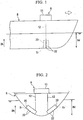
- FIGS. 1 to 5 A ship as a first embodiment of the present invention will be described with referring FIGS. 1 to 5 .
- the ship of the present embodiment includes a hull B, and a device for reducing frictional resistance A reducing a frictional resistance by blowing out a gas into the water outside of the hull.
- the device for reducing frictional resistance A includes air-supply device 11, a chamber 20 blowing out air to the outside of the hull, and a supply pipe 12 guiding air from the air-supply device 11 to the chamber 20.
- the air-supply device 11 has a blower or compressor blowing out a compressed air by suctioning the air.
- the compressed air generated in the air-supply device 11 is supplied to an internal space Si of the chamber 20 via the supply pipe 12.
- the chamber 20 is provided in a draft part Bd of the hull B and a part where a width of the hull B varies when a position of a height direction Dh of the hull B is changed by a change of the width of the hull B.
- the chamber 20 is provided in the draft part Bd of the hull B and a part where an outer wall of the hull is inclined with respect to a horizontal surface. As shown in FIG.
- the chamber 20 includes an outer-wall plate 21 inclining with respect to the horizontal surface in a part of the outer wall of the hull, a supply-pipe-connecting plate 23 disposing inside the hull with respect to the outer-wall plate 21 and facing the outer-wall plate 21 with a clearance, and a peripheral-wall plate 24 extending to the outer-wall plate 21 from the outer circumferential edge of the supply-pipe-connecting plate 23.
- the chamber 20 forms the internal space Si by enclosing it with the outer-wall plate 21, the supply-pipe-connecting plate 23 and the peripheral-wall plate 24.
- a plurality of blowing holes 22 penetrating to the outside of the hull from the internal space Si are formed in the outer-wall plate 21 of the chamber 20.
- the plurality of blowing holes 22 are formed in different positions from each other in the height direction Dh of the hull B.
- the shapes and areas of the plurality of blowing holes 22 are the same in each blowing hole.
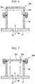
- a supply pipe 12 is connected to the supply-pipe-connecting plate 23 of the chamber 20. As shown in FIG. 5 , in an outer periphery of the supply-pipe-connecting plate 23, a bolt-insertion hole 23a penetrating toward the outer-wall plate 21 and a seal groove 23b into which a seal member 27 fits are formed.
- the peripheral-wall plate 24 of the chamber 20 is formed of a peripheral wall 25 extending toward the outer-wall plate 21 from the supply-pipe-connecting plate 23 and a flange 26 protruding outward from an end of the peripheral wall 25 at the side of the supply-pipe-connecting plate 23 along the supply-pipe-connecting plate 23; and in the flange 26, a seal groove 26b is formed at a position facing the seal groove 23b of the supply-pipe-connecting plate 23 and a bolt-insertion hole 26a is formed at a position facing the bolt-insertion hole 23a of the supply-pipe-connecting plate 23. As shown in FIG.
- the supply-pipe-connecting plate 23 is connected to the peripheral wall plate 24 by a bolt 28a inserted into the bolt-insertion hole 23a of the supply-pipe-connecting plate 23 and the bolt-insertion hole 26a of the peripheral-wall plate 24 and a nut 28b into which the bolt 28a is screwed.
- An end of the peripheral-wall plate 24 at the side of the outer-wall plate 21 in the peripheral wall 25 is joined to the outer-wall plate 21 by welding or the like.
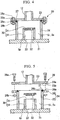
- the device for reducing frictional resistance A of the present embodiment further includes a distributor 30 provided to each of the plurality of blowing holes 22 and guiding a part of an air, which is supplied into the chamber 20, to the blowing hole 22 from the supply pipe 12.
- the distributor 30 includes a cylinder 34 and a cover 31.
- One side of the cylinder 34 is joined to a portion on the outer-wall plate 21 and around one blowing hole 22.
- the other side of the cylinder 34 is connected to the cover 31 and an opening of the other side of the cylinder 34 is covered by the cover 31.
- a partial space Sp is formed by a space which is surrounded by the outer-wall plate 21 and the cylinder 34 and cover 31 of the distributor 30.
- the cylinder 34 and cover 31 of the distributor 30 form a partition member sectioning the internal space Si of the chamber 20 into a supply-pipe-side space Ss communicating with an opening of the supply pipe 12 and a partial space Sp of each of the plurality of blowing holes 22. At least one penetration hole 32 penetrating toward the partial space Sp from the supply-pipe-side space Ss is formed in the cover 31 of the distributor 30.
- the number of the penetration hole 32 of each of the plurality of distributors 30 is different for each other, as shown in FIG. 3 .
- the number of the penetration hole 32 of the distributor 30 corresponding to the blowing hole 22 placed at a position higher than the adjacent blowing hole is less than the number of the penetration hole 32 of the distributor 30 corresponding to the blowing hole 22 placed at a position lower than the adjacent blowing hole.
- An opening area of the penetration hole 32 is the same in each of the plurality of penetration holes 32.
- the penetration hole 32 of each of the plurality of distributors 30 works as a flow-amount adjuster adjusting the flow amount of the air guided to the blowing hole 22 corresponding to the distributor 30.
- the air from the air-supply device 11 is supplied to the supply-pipe-side space Ss inside the chamber 20 via the supply pipe 12 (gas supplying step).
- the air supplied to the supply-pipe-side space Ss is guided to the blowing hole 22 corresponding to each distributor 30 by the plurality of distributors 30 and is blown out into the water outside of the hull from the blowing hole 22 (gas distributing step).
- the lower the height position of the blowing hole 22 is, the higher water pressure this blowing hole 22 is subjected to from the outside of the hull, and the water resistance with respect to the air blown out from the blowing hole 22 into the water increases. Therefore, in the present embodiment, the flow amount of the air blown out from the plurality of blowing holes 22 placed at different heights from each other is equalized. In addition, in the present embodiment, since the shapes and areas of the opening of the plurality of blowing holes 22 are the same, the dispersion along the outer wall of the hull of the air blown out from the plurality of blowing holes 22 is equalized.
- the dispersion along the outer wall of the hull of the air blown out from the plurality of blowing holes 22 is equalized along with the flow amount of the air blown out from the plurality of blowing holes 22 being equalized, a distribution of the air along the outer wall of the hull can be equalized.
- the frictional resistance of the hull B can be reduced by more than in the prior art.
- the peripheral plate 24 of the chamber 20 and the supply-pipe-connecting plate 23 are connected together by bolting.
- the chamber 20 is released. Accordingly, in the present invention, checking, repairing work and the like of the inside of the chamber 20 can be easily performed.
- the peripheral plate 24 of the chamber 20 and the supply-pipe-connecting plate 23 can be connected together by welding.
- the connection between the cover and cylinder of the distributor can be connected by bolting similarly to the peripheral plate 24 of the chamber 20 and the supply-pipe-connecting plate 23.
- FIGS. 6 to 9 A modification of a first embodiment will be described with referring FIGS. 6 to 9 .
- the air flown into the partial space Sp from the one penetration hole flows straight and the air is blown to the outside of the hull from the blowing hole without any change.
- the flow amount of the air blown from the blowing hole depends on the flow amount of the air flown into the partial space Sp from the one penetration hole, and a desired flow amount may not be achieved.
- a penetration hole 32a is formed in a cylinder 34a of the distributor 30a.
- the penetration direction of the penetration hole 32a formed in the cylinder 34a is different from the penetration direction Dp of the blowing hole 22 formed in the outer-wall plate 21, and the air flown into the partial space Sp from the penetration hole 32a does not flow into the blowing hole 22 by flowing straight.
- a plurality of penetration holes 32b are formed in a cover 31 b of the distributor 30b in the same manner as the distributor 30 of the aforementioned first embodiment.
- a penetration hole 32b does not exist on an extension of the blowing hole 22 in the penetration direction Dp of the blowing hole 22.
- the air flown into the partial space Sp from the penetration hole 32b does not flow into the blowing hole 22 by flowing straight.
- a penetration hole 32c is formed in a cover 31c of the distributor 30c in the same manner as the distributor 30 of the aforementioned first embodiment.
- a baffle plate (a change-direction member) 35 changing the direction of the air flown into the partial space Sp from the penetration hole 32c is provided between the penetration hole 32c and the blowing hole 22.
- the air flown into the partial space Sp from the penetration hole 32c does not flow into the blowing hole 22 by flowing straight.
- a penetration holes 32d are formed in a cover 31d of the distributor 30d in the same manner as the distributor 30 of the aforementioned first embodiment.
- a bending pipe (a change-direction member) 36 is connected to the partial space Sp side of the penetration hole 32d.
- the cover and cylinder of the distributor are connected by the bolt 37 so that the cover can be separated from the cylinder easily.
- the distributor 30 only in the ship of the first embodiment is different therefrom, and the other structures are the same as in the first embodiment. Also, in the embodiments and modifications described hereinafter, the distributor 30 only in the ship of the first embodiment is different therefrom, and the other structures are the same as in the first embodiment. Thus, in the description hereinafter, the distributor is mainly explained.
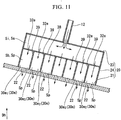
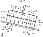
- a plurality of distributors 30e of the present embodiment includes an internal-space-partition plate 38 sectioning the internal space Si of the chamber 20 into a blowing-side space Sb at the outer-wall plate 21 side and the supply-pipe-side space Ss at the supply-pipe-connecting plate 23 side, and a plurality of blowing-side-partition plates 39 dividing the blowing-side space Sb into a plurality of partial spaces Sp by sectioning the blowing-side space Sb with respect to each blowing hole 22.
- the internal-space-partition plate 38 and the plurality of blowing-side-partition plates 39 included in the plurality of distributors 30e are formed as a partition member sectioning the internal space Si of the chamber 20 into the supply-pipe-side space Ss communicating to the opening of the supply pipe 12 and the partial space Sp of each of the plurality of blowing holes 22.
- the internal space Si is sectioned by part of the peripheral-wall plate 24 of the chamber 20, part of the internal-space-partition plate 38, and one blowing-side-partition plate 39.
- the internal space Si is sectioned by part of the peripheral-wall plate 24 of the chamber 20, part of the internal-space-partition plate 38, and two blowing-side-partition plates 39 adjacent to each other.
- the number of the penetration hole 32e of each of the plurality of distributors 30e is different for each of the distributors in the same manner as the first embodiment. Specifically, the number of the penetration hole 32e of the distributor 30e corresponding to the blowing hole 22 placed in a position higher than the adjacent blowing hole is less than the number of the penetration hole 32e of the distributor 30e corresponding to the blowing hole 22 placed in a position lower than the adjacent blowing hole.
- An opening area of the penetration hole 32e is the same in each of the plurality of penetration holes 32e.
- the penetration hole 32e of each of the plurality of distributors 30e works as a flow-amount adjuster adjusting the flow amount of the air guided to the blowing hole 22 corresponding to the distributor 30e.
- the present embodiment is different from the first embodiment in terms of the structure of the partition member sectioning the internal space Si of the chamber 20 into the supply-pipe-side space Ss and the plurality of partial spaces Sp.
- the flow-amount adjuster of each of the plurality of distributors 30e is the same as in the first embodiment.
- the flow amount of the air blown out from the plurality of blowing holes 22 different in height to each other can be equalized in the same manner as the first embodiment.
- the shapes and areas of the opening of the plurality of blowing holes 22 are the same, the dispersion along the outer wall of the hull of the air blown out from the plurality of blowing holes 22 is equalized.
- a distribution of the air along the outer wall of the hull can be equalized, and the frictional resistance of the hull B can be further reduced.
- the number of the penetration holes 32e of each of the plurality of distributors 30e is different for each of the distributors 30e.
- the number of penetration holes 32f of each of a plurality of distributors 30f is the same in each of the distributors 30f, but an opening area of the penetration hole 32f of each of a plurality of distributors 30f is different for each of the distributors 30f.
- the opening area of the penetration hole 32f of the distributor 30f corresponding to the blowing hole 22 placed at a position higher than the adjacent blowing hole is smaller than the opening area of the penetration hole 32f of the distributor 30f corresponding to the blowing hole 22 placed at a position lower than the adjacent blowing hole.
- the penetration hole 32f of each of the plurality of distributors 30f works as a flow-amount adjuster adjusting the flow amount of air guided to the blowing hole 22 corresponding to the distributor 30f.
- the flow amount of the air blowing from each of the blowing holes can be equalized, and the frictional resistance of the hull B can be reduced in the same manner as in each of the aforementioned embodiments and modifications.
- FIGS. 14 to 16 A second modification of the second embodiment will be explained using FIGS. 14 to 16 .
- an opening is formed in each of the plurality of partial spaces Sp.
- a screen 32g is provided on each opening of the internal-space-partition plate 38. That is, a screen 32g guiding the air of the supply-pipe-side space Ss into the partial space Sp of the relevant distributor is provided on each of a plurality of distributors 30g.
- a size of openings of the screen 32g of each of the plurality of distributors 30g is different for each of the distributors 30g. Specifically, the size of openings of the screen 32g of the distributor 30g corresponding to the blowing hole 22 placed at a position higher than the adjacent blowing hole is smaller than the size of openings of the screen 32g of the distributor 30g corresponding to the blowing hole 22 placed at a position lower than the adjacent blowing hole.
- the screen 32g of each of the plurality of distributors 30g works as a flow-amount adjuster adjusting the flow amount of air guided to the blowing hole 22 corresponding to the distributor 30g.
- the flow amount of the air blowing from each of the blowing holes can be equalized, and the frictional resistance of the hull B can be reduced in the same manner as in each of the aforementioned embodiments and modifications.
- FIG. 17 A third modification of the second embodiment will be explained using FIG. 17 .
- a perforated plate 32h is provided instead of the screen 32g of the second modification of the second embodiment. That is, in the present modification, the perforated plate 32h guiding the air of the supply-pipe-side space Ss into the partial space Sp of the relevant distributor is provided on each of a plurality of distributors 30h. An opening area of one penetration hole 32e in the perforated plate 32h of each of the plurality of distributors 30h is different for each of the distributors 30h.
- the opening area of one penetration hole 32e of the distributor 30h corresponding to the blowing hole placed at a position higher than the adjacent blowing hole is smaller than the opening area of the penetration hole 32e of the distributor 30h corresponding to the blowing hole placed at a position lower than the adjacent blowing hole.
- the higher the height position of the blowing hole corresponding to the distributor 30h is, the more the flow amount of air guided to the corresponding blowing hole is reduced. Therefore, in the present modification, the perforated plate 32h of each of the plurality of distributors 30h works as a flow-amount adjuster adjusting the flow amount of air guided to the blowing hole corresponding to the distributor 30h.
- the flow amount of the air blowing from each of the blowing holes can be equalized, and frictional resistance of the hull B can be reduced in the same manner as in each of the aforementioned embodiments and modifications.
- a pipe 32i is provided in each of the plurality of partial spaces Sp. That is, in the present modification, the pipe 32i guiding the air of the supply-pipe-side space Ss into the partial space Sp of the relevant distributor is provided on each of a plurality of distributors 30i. On each of the distributors 30i, one pipe 32i is provided. The inner diameter (or the opening area) of the pipe 32i of each of the plurality of distributors 30i is different for each of the distributors 30i.
- the inner diameter (or the opening area) of the pipe 32i of the distributor 30i corresponding to the blowing hole 22 placed at a position higher than the adjacent blowing hole is smaller than the inner diameter (or the opening area) of the pipe 32i of the distributor 30h corresponding to the blowing hole placed at a position lower than the adjacent blowing hole.
- the pipe 32i of each of the plurality of distributors 30g works as a flow-amount adjuster adjusting the flow amount of air guided to the blowing hole 22 corresponding to the distributor 30i.
- the flow amount of the air blowing from each of the blowing holes can be equalized, and the frictional resistance of the hull B can be reduced in the same manner as in each of the aforementioned embodiments and modifications.
- FIGS. 19 and 20 A fifth modification of the second embodiment will be explained using FIGS. 19 and 20 .
- a pipe 33j and a valve 32j are provided to each of the plurality of partial spaces Sp. That is, in the present modification, the pipe 33j and the valve 32j which guide the air of the supply-pipe-side space Ss into the partial space Sp of the relevant distributor is provided on each of a plurality of distributors 30j. On each distributor 30j, one pipe 33j is provided. On one pipe 33j, one valve 32j is provided. A valve opening position of the valve 32j of each of the plurality of distributors 30j is different for each of the distributors 30j.
- valve opening position of the valve 32j of the distributor 30j corresponding to the blowing hole 22 placed at a position higher than the adjacent blowing hole is smaller than the valve opening position of the valve 32j of the distributor 30j corresponding to the blowing hole 22 placed at a position lower than the adjacent blowing hole.
- the valve 32j of each of the plurality of distributors 30j works as a flow-amount adjuster adjusting the flow amount of air guided to the blowing hole 22 corresponding to the distributor 30j.
- the flow amount of the air blowing from each of the blowing holes can be equalized, and the frictional resistance of the hull B can be reduced in the same manner as in each of the aforementioned embodiments and modifications.
- FIGS. 21 to 24 A distributor of a third embodiment will be explained using FIGS. 21 to 24 .
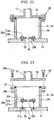
- a plurality of distributors 30k of the present embodiment includes a facing plate 31k facing the blowing hole 22 corresponding to the distributor 30k and facing a portion around the blowing hole 22 in the outer-wall plate 21, and a bolt 37k fixing the facing plate 31 k to the outer-wall plate 21 so that the facing plate 31k is made to contact the outer-wall plate 21.
- the bolt 37k is inserted into a bolt hole 33k of the facing plate 31k and is screwed into a screw hole 21 a formed in the outer-wall plate 21.
- the facing plate 31 k forms a partition member sectioning the internal space Si to the partial space Sp including a space in the blowing hole 22 and the supply-pipe-side space Ss. In this facing plate 31k, a penetration hole 32k penetrating from the supply-pipe-side space Ss side to the partial space Sp is formed.
- the number of penetration holes 32k of each of a plurality of distributors 30k is the same in each of the distributors 30k, but the opening area of the penetration hole 32k of each of a plurality of distributors 30k is different for each of the distributors 30k.
- the opening area of the penetration hole 32k of the distributor 30k corresponding to the blowing hole 22 placed at a position higher than the adjacent blowing hole is smaller than the opening area of the penetration hole 32k of the distributor 30k corresponding to the blowing hole 22 placed at a position lower than the adjacent blowing hole. Therefore, also in the present embodiment, the penetration hole 32k of each of the plurality of distributors 30k works as a flow-amount adjuster adjusting the flow amount of air guided to the blowing hole 22 corresponding to the distributor 30k.
- the flow amount of the air blowing from each of the blowing holes can be equalized, and the frictional resistance of the hull B can be reduced in the same manner as in each of the aforementioned embodiments and modifications.
- the distributor 30k is configured by the facing plate 31k and the bolts 37, and since the structure of the distributor 30k is simple, the production cost of the distributor 30k can be reduced.
- the distributor 30k is not provided to the blowing hole 22 placed at the lowest height position; however, the distributor 30k can be provided to the blowing hole 22 placed at the lowest height position.
- a baffle plate as shown in FIG. 8 can be disposed inside the partial space Sp which is a space in the blowing hole 22.
- FIGS. 25 to 26 A distributor of a fourth embodiment will be explained using FIGS. 25 to 26 .
- a plurality of distributors 30m of the present embodiment includes a facing plate 31 m facing the blowing hole 22 corresponding to the distributor 30m and a portion around the blowing hole 22 in the outer-wall plate 21 with a clearance D, and a clearance-maintaining member 37m maintaining the clearance D between the facing plate 31m and the outer-wall plate 21.
- the clearance-maintaining member 37m includes a bolt 38m penetrating the facing plate 31m and screwing into the outer-wall plate 21 and a spacer 39m into which a bolt shank of the bolt 38m is inserted and which maintains the clearance D between the facing plate 31 m inserted and the outer-wall plate 21.
- the partial space Sp is formed by a space combined by a space sandwiched between the facing plate 31 m and the outer-wall plate 21 and a space in the blowing hole 22. Also, in this distributor 30m, an opening 32m between an outer circumferential edge of the facing plate 31m and the outer-wall plate 21 is an opening into which the air flows from the supply-pipe-side space Ss side to the partial space Sp.
- the clearance D between the facing plate 31 m and the outer-wall plate 21 is different for each of the distributors 30m. Specifically, the size of the clearance D between the facing plate 31 m of the distributor 30m corresponding to the blowing hole 22 placed at a position higher than the adjacent blowing hole and the outer-wall plate 21 is smaller than the size of the clearance D between the facing plate 31m of the distributor 30m corresponding to the blowing hole 22 placed at a position lower than the adjacent blowing hole and the outer-wall plate 21.
- the opening 32m of each of the plurality of distributors 30m works as a flow-amount adjuster adjusting the flow amount of air guided to the blowing hole 22 corresponding to the distributor 30m.
- the flow amount of the air blowing from each of the blowing holes can be equalized, and the frictional resistance of the hull B can be reduced in the same manner as in each of the aforementioned embodiments and modifications.
- the distributor 30m is configured by the facing plate 31m and the clearance-maintaining member 37m, and since the structure of the distributor 30m is simple, the production cost of the distributor 30m can be reduced in the same manner as in the third embodiment.
- a distributor 30e of a fifth embodiment will be explained using FIG. 27 .
- a distributor 30n of the present embodiment is a modification of the distributor 30 of the first embodiment.
- a partition member in the distributor 30n of the present embodiment includes a cylinder 34 and a cover 31 in the same manner as in the first embodiment.
- One side of the cylinder 34 is joined to a portion on the outer-wall plate 21 and around one blowing hole 22.
- the other side of the cylinder 34 is connected to the cover 31 and an opening on the other side of the cylinder 34 is covered by the cover 31.
- a partial space Sp is formed by a space which is surrounded by the outer-wall plate 21, the cylinder 34 and cover 31 of the distributor 30.
- a pipe 32n guiding the air of the supply-pipe-side space Ss to the partial space Sp is connected to the cover 31.
- an inner diameter of the pipe 32n of each of the plurality of distributors 30n is the same, but a length of the pipe 32n is different for each of the distributors 30n.
- the length of the pipe 32n of the distributor 30n corresponding to the blowing hole 22 placed at a position higher than the adjacent blowing hole is shorter than the length of the pipe 32n of the distributor 30n corresponding to the blowing hole 22 placed at a position lower than the adjacent blowing hole.
- the pipe 32n of each of the plurality of distributors 30n works as a flow-amount adjuster adjusting the flow amount of air guided to the blowing hole 22 corresponding to the distributor 30n.
- the length of the pipe of the distributor 30na corresponding to the blowing hole 22 placed at the lowest position is zero here.
- the pipe is not connected to the distributor 30na corresponding to the blowing hole 22 placed at the lowest position.
- a penetration hole 32na having the same inner diameter as an inner diameter of the pipe 32n connected to the other distributors 30n is formed.
- the flow amount of the air blowing from each of the blowing holes can be equalized, and the frictional resistance of the hull B can be reduced in the same manner as in each of the aforementioned embodiments and modifications.
- the pipe 32n is not provided to the distributor 30na corresponding to the blowing hole 22 placed at the lowest height position; however, the pipe 32n can also be provided to this distributor 30na.
- the pipe 32n is bent, but the pipe 32n may not be bent.
- the length of the pipe 32n can be easily secured in the chamber 20 if the pipe 32n is bent. In this manner, when the pipe 32n is bent, a curve thereof becomes the resistance of the pipe to the air. Therefore, when the flow amount of air passing through the pipe 32n is configured, the number of curves of the pipe 32n is preferable to be considered.
- FIGS. 6 to 9 are the modifications with respect to the first embodiment.
- the modifications shown in FIGS. 7 to 9 can be applied to the second embodiment, the first modification of the second embodiment, the fourth modification of the second embodiment, the fifth modification of the second embodiment and the fifth embodiment.
- the modification shown in FIG. 8 can be applied to the first modification and fourth modification of the second embodiment.
- the distributor is provided to each of all the blowing holes 22.
- the distributor which imparts a resistance to the flow of air and reduces air pressure, may not be provided to the blowing hole 22 which the highest water pressure from the outside of the hull is subjected to and which is placed at the lowest position as described in the third embodiment and fourth embodiment. That is, the distributor will be provided at least to the plurality of blowing holes 22 except for the blowing hole 22 placed at the lowest position. In this manner, the production cost can be suppressed by excepting the distributor corresponding to the blowing hole 22 placed at the lowest position.
- the flow amount of air blown out from all of the blowing holes 22 formed in the outer-wall plate 21 of the chamber 20 is adjusted by the flow-amount adjuster of the distributor of the blowing hole 22 except for the blowing hole 22 placed at the lowest position so as to be equalized in each blowing hole 22.
- the distributor may not be provided to the blowing hole 22 placed at the lowest position.
- the distributor may not be provided to the blowing hole 22 placed at the lowest position.
- the flow-amount adjuster of the first embodiment is a penetration hole 32, the number of which is different for each of the distributors 30.
- any of the flow-amount adjusters shown in FIGS. 13 to 20 can be used.
- the flow-amount adjuster of the third embodiment is the penetration hole 32e, the opening area of which is different for each of the distributors 30k.
- any of the flow-amount adjusters of the first embodiment and second embodiment and any of the flow-amount adjusters shown in FIGS. 14 to 20 can be applied.
- the fifth embodiment is a modification of the first embodiment, but the flow-amount adjuster shown in the fifth embodiment can be applied to the second embodiment, the first modification of the second embodiment and the third embodiment.
- the flow-amount adjuster of the distributor can be a variety of forms if it is an adjuster adjusting a pressure loss of when the air flows into the partial space Sp from the supply-pipe-side space Ss.
- the flow-amount adjuster of the distributor can be, for example, in any of the following forms.
- a plate facing the outer-wall plate 21 with clearance is served as the supply-pipe-connecting plate 23, and the supply pipe 12 is connected to this supply-pipe-connecting plate 23.
- the peripheral-wall plate 24 connected to the outer-wall plate 21 is served as a supply-pipe-connecting plate, and the supply pipe 12 can be connected to this supply-pipe-connecting plate.
- one blowing hole 22 corresponds to one distributor.
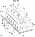
- a plurality of blowing holes 22, 22 can correspond to one distributor 30e.
- blowing holes 22, 22 placed at a common position in the height direction Dh correspond to one distributor 30e.
- the case of a common position in the height direction Dh includes not only the case where the positions of the plurality of blowing holes 22, 22 in the height direction Dh are fully match but also the case where the plurality of blowing holes 22, 22 have an overlapping part DL in the height direction Dh.
- the plurality of blowing holes 22, 22 being in a common position in the height direction Dh can correspond to one distributor.
- every opening shape of the blowing hole 22 is a circle, but the shape can be a rectangle, a square, a rhombus, a triangle, a triangle having rounded corners, an oblong, and ellipse, or other shapes.
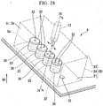
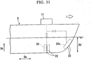
- the chamber 20 is provided in the draft part Bd and in a part where a width of the hull B varies when a position of a height direction Dh of the hull B is changed.
- a chamber 20x is provided in the draft part Bd and at a part where a position on the outer wall of the hull B varies in the front and rear direction Da of the hull B when a position of the hull B changes in the height direction Dh.
- the device for reducing frictional resistance ship including such a device, and method of reducing frictional resistance of the ship of the present invention
- equalization of the flow amount of the air blown out from the plurality of blowing holes and equalization of dispersing along the outboard-wall of the air blown out from the plurality of blowing holes can be achieved. Therefore, the frictional resistance of the ship can be further reduced.
Landscapes
- Physics & Mathematics (AREA)
- Fluid Mechanics (AREA)
- Chemical & Material Sciences (AREA)
- Engineering & Computer Science (AREA)
- Combustion & Propulsion (AREA)
- Mechanical Engineering (AREA)
- Ocean & Marine Engineering (AREA)
- Filling Or Discharging Of Gas Storage Vessels (AREA)
Claims (22)
- Eine Vorrichtung (A) zur Minderung von Reibungswiderstand eines Schiffs, wobei die Vorrichtung aufweist:eine Kammer (20), die an einem Tiefgangteil eines Rumpfs (B) vorgesehen ist und in der eine Vielzahl von Ausblaslöchern (22), welche ein Gas in das Wasser der Außenseite des Rumpfs von voneinander in einer Höhenrichtung des Rumpfs unterschiedlichen Positionen ausblasen, ausgebildet sind,ein Zuführrohr (12), das das Gas zu einem Innenraum (Si) der Kammer zuführt,dadurch gekennzeichnet, das die Vorrichtung aufweisteine Vielzahl von Verteilern (30), von denen jeder zumindest an jedem der Vielzahl von Ausblaslöchern (22) mit Ausnahme des Ausblaslochs, das an der untersten Position in der Höhenrichtung der Vielzahl von Ausblaslöchern angeordnet ist, vorgesehen ist, wobei der Verteiler (30) einen Teil des Gases, das von dem Zuführrohr (12) in die Kammer zugeführt wird, zu jedem der Ausblaslöcher (22) leitet,wobei jeder der Vielzahl von Verteilern (30) einen Strömungsmengeneinsteller (32) besitzt, der eine Strömungsmenge des zu dem dem Verteiler entsprechenden Au-sblasloch (22) geleiteten Gases so einstellt, dass die Strömungsmenge des von der Vielzahl von Ausblaslöchern (22) ausgeblasenen Gases in jedem der Ausblaslöcher gleichmäßig gemacht wird.
- Die Vorrichtung zur Minderung von Reibungswiderstand eines Schiffs gemäß Anspruch 1, wobei
der Verteiler (30) an allen von der Vielzahl von Ausblaslöchern (22), die in der Kammer ausgebildet sind, vorgesehen ist. - Die Vorrichtung zur Minderung von Reibungswiderstand eines Schiffs gemäß Anspruch 1 oder 2, wobei
der Strömungsmengeneinsteller der Vielzahl von Verteilern (30) die Strömungsmenge des zu dem entsprechenden Ausblasloch geleiteten Gases umso mehr verringert, je höher die Höhenposition des entsprechenden Ausblaslochs (22) ist. - Die Vorrichtung zur Minderung von Reibungswiderstand eines Schiffs gemäß Anspruch 3, wobei
die Vielzahl von Verteilern (30) aufweist:ein Trennelement, das den Innenraum der Kammer (20) in einen zuführrohrseitigen Raum, welcher mit einer Öffnung des Zuführrohrs (12), das mit der Kammer verbunden ist, kommuniziert, und einen Teilraum (Sp), der einen Raum des entsprechenden Ausblaslochs (22) umfasst, unterteilt, undwobei der Strömungsmengeneinsteller an dem Trennelement vorgesehen ist. - Die Vorrichtung zur Minderung von Reibungswiderstand eines Schiffs gemäß Anspruch 4, wobei
der Strömungsmengeneinsteller des Verteilers mit mindestens einem Durchsatzloch (32) konfiguriert ist, das in dem Trennelement (31) ausgebildet ist und von dem zuführrohrseitigen Raum (Ss) zu der Seite des Teilraums (Sp) hindurchreicht, und
die Anzahl von Durchsatzlöchern (32) von jedem der Vielzahl von Verteilern (30) bei jedem der Vielzahl der Verteiler unterschiedlich ist. - Die Vorrichtung zur Minderung von Reibungswiderstand eines Schiffs gemäß Anspruch 4, wobei
der Strömungsmengeneinsteller des Verteilers (30) in dem Trennelement ausgebildet ist und mit einem Durchsatzloch (32) konfiguriert ist, das von dem zuführrohrseitigen Raum (Ss) zu der Seite des Teilraums hindurchreicht, und
ein Öffnungsbereich des Durchsatzlochs von jedem der Vielzahl von Verteilern bei jedem der Vielzahl von Verteilern unterschiedlich ist. - Die Vorrichtung zur Minderung von Reibungswiderstand eines Schiffs gemäß Anspruch 5 oder 6, wobei
Von Plattenelementen, die die Kammer bilden, das Durchsatzloch (32) nicht an einer Verlängerung des Ausblaslochs (22) in der Durchsatzrichtung des Ausblaslochs in einer Außenwandplatte ausgebildet ist, in der das dem Verteiler entsprechende Ausblasloch ausgebildet ist. - Die Vorrichtung zur Minderung von Reibungswiderstand eines Schiffs gemäß Anspruch 5 oder 6, wobei
ein Richtungsänderungselement (35), das die Strömungsrichtung des Gases von dem Durchsatzloch ändert, in dem Teilraum vorgesehen ist. - Die Vorrichtung zur Minderung von Reibungswiderstand eines Schiffs gemäß Anspruch 4, wobei
der Strömungsmengeneinsteller von jedem der Vielzahl von Verteilern (30) ein Sieb oder eine Blende (35) ist, das bzw. die an den Trennelement vorgesehen und mit einer Vielzahl von Öffnungen ausgebildet ist, durch welche das Gas von dem zuführrohrseitigen Raum zu der Seite des Teilraums passiert, und
eine Größe von Öffnungen des Siebs oder der Blende (32g) von jedem der Vielzahl von Verteilern bei der jedem der Vielzahl von Verteilern unterschiedlich ist. - Die Vorrichtung zur Minderung von Reibungswiderstand eines Schiffs gemäß Anspruch 4, wobei
der Strömungsmengeneinsteller von jedem der Vielzahl von Verteilern (30) mit einem Rohr ausgebildet ist, das an dem Trennelement vorgesehen ist und durch welches das Gas von dem zuführrohrseitigen Raum (Ss) zu der Seite des Teilraums passiert, und
ein Öffnungsbereich des Rohrs von jedem der Vielzahl von Verteilern bei jedem der Vielzahl von Verteilern unterschiedlich ist. - Die Vorrichtung zur Minderung von Reibungswiderstand eines Schiffs gemäß Anspruch 4, wobei
der Strömungsmengeneinsteller von jedem der Vielzahl von Verteilern (30) mit einem Rohr (32i, 32n) konfiguriert ist, das an dem Trennelement vorgesehen ist und durch welches das Gas von dem zuführrohrseitigen Raum zu der Seite des Teilraums passiert, und
eine Länge des Rohrs von jedem der Vielzahl von Verteilern bei jedem der Vielzahl von Verteilern unterschiedlich ist. - Die Vorrichtung zur Minderung von Reibungswiderstand eines Schiffs gemäß Anspruch 4, wobei
der Strömungsmengeneinsteller von jedem der Vielzahl von Verteilern (30) mit einem Ventil (32j) konfiguriert ist, das an dem Trennelement vorgesehen ist und durch welches das Gas von dem zuführrohrseitigen Raum zu der Seite des Teilraums passiert, und
eine Ventilöffnungsposition des Ventils (32j) von jedem der Vielzahl von Verteilern bei jedem der Vielzahl von Verteilern unterschiedlich ist. - Die Vorrichtung zur Minderung von Reibungswiderstand eines Schiffs gemäß einem der Ansprüche 4 bis 12, wobei
das Trennelement des Verteilers einen Zylinder (34) und eine Abdeckung (31) aufweist, wobei der Zylinder (34) den Teilraum (Sp) in der Kammer (22) bildet, wobei ein Ende des Zylinders (34) mit der Außenwandplatte verbunden ist, in welcher das entsprechende Ausblasloch ausgebildet ist und die in den die Kammer bildenden Plattenelementen enthalten ist, und wobei die Abdeckung (31) eine Öffnung des anderen Endes des Zylinders abdeckt. - Die Vorrichtung zur Minderung von Reibungswiderstand eines Schiffs gemäß einem der Ansprüche 4 bis 12, wobei
das Trennelement der Vielzahl von Verteilern aufweist:eine Innenraumtrennplatte (38), die den Innenraum der Kammer in zwei Räume bestehend aus dem zuführrohrseitigen Raum und einem ausblasseitigen Raum, der als ein anderer Raum definiert ist, unterteilt, undeine ausblasseitige Trennplatte (39), die den ausblasseitigen Raum in eine Vielzahl von Teilräumen unterteilt, indem der ausblasseitige Raum bezüglich jedem Ausblasloch unterteilt ist, undwobei der Strömungsmengeneinsteller an der Innenraumtrennplatte vorgesehen ist. - Die Vorrichtung zur Minderung von Reibungswiderstand eines Schiffs gemäß einem der Ansprüche 4 bis 6 und 9 bis 12, wobei
das Trennelement des Verteilers aufweist:eine Gegenplatte (31k), die dem entsprechenden Ausblasloch (22) zugewandt ist und die einem Abschnitt um das entsprechende Ausblasloch in der Außenwandplatte, in der das Ausblasloch ausgebildet ist, zugewandt ist und die in den die Kammer bildenden Plattenelementen enthalten ist, und wobei die Gegenplatte in Kontakt mit der Außenwandplatte ist, undwobei der Strömungsmengeneinsteller an der Gegenplatte vorgesehen ist. - Die Vorrichtung zur Minderung von Reibungswiderstand eines Schiffs gemäß Anspruch 4, wobei
das Trennelement des Verteilers aufweist:eine Gegenplatte, die dem entsprechenden Ausblasloch und einem Abschnitt um das entsprechende Ausblasloch in der Außenwandplatte herum, in welcher das Ausblasloch ausgebildet ist, zugewandt ist, und die in den die Kammer bildenden Plattenelementen enthalten ist, mit einem Zwischenraum zwischen dem Gegenplattenelement und der Außenwandplatte undein Zwischenraumhalteelement (37m) das den Zwischenraum zwischen der Gegenplatte und der Außenwandplatte einhält,wobei der Strömungsmengeneinsteller mit einer Öffnung konfiguriert ist, die zwischen dem Rand der Gegenplatte und der Außenwandplatte vorgesehen ist, undwobei ein Bereich der Öffnung von jedem der Vielzahl von Verteilern (30) bei jedem der Vielzahl von Verteilern (30) unterschiedlich ist. - Die Vorrichtung zur Minderung von Reibungswiderstand eines Schiffs gemäß einem der Ansprüche 1 bis 16, wobei
Formen und Öffnungsbereiche einer Öffnung von jedem der Vielzahl von Ausblaslöchern (22) zueinander gleich sind. - Die Vorrichtung zur Minderung von Reibungswiderstand eines Schiffs gemäß einem der Ansprüche 1 bis 17, wobei
die Ausblaslöcher (22) an derselben Position in der Höhenrichtung zueinander in der Kammer ausgebildet sind, und
der Verteiler an jedem der Ausblaslöcher an derselben Position in der Höhenrichtung zueinander vorgesehen ist. - Ein Schiff mit:dem Rumpf (B) undder Vorrichtung (A) zur Verringerung von Reibungswiderstand eines Schiffs gemäß einem der Ansprüche 1 bis 18.
- Ein Verfahren zur Minderung von Reibungswiderstand eines Schiffs, wobei das Verfahren aufweist:einen Gaszuführschritt des Zuführens eines Gases zu einem Innenraum (Si) einer Kammer (20), wobei die Kammer an einem Tiefgangteil eines Rumpfs (B) vorgesehen ist und in der eine Vielzahl von Ausblaslöchern (22) zum Ausblasen des Gases in das Wasser der Außenseite des Rumpfs von unterschiedlichen Positionen voneinander in der Höhenrichtung des Rumpfs ausgebildet sind, undeinem Gasverteilungsschritt des Leitens eines Teils des Gases, das ins Innere der Kammer (20) zugeführt wird, zu den Ausblaslöchern in jedem der Vielzahl von Ausblaslöchern,wobei der Gasverteilungsschritt den Schritt des Einstellens einer Strömungsmenge des zu dem Ausblasloch (22) geleiteten Gases aufweist, sodass die Strömungsmenge des von der Vielzahl von Ausblaslöchern ausgeblasenen Gases in jedem der Vielzahl von Ausblaslöchern gleichmäßig gemacht wird.
- Das Verfahren zur Minderung von Reibungswiderstand eines Schiffs gemäß Anspruch 20, wobei
in dem Gasverteilungsschritt die Strömungsmenge des zu dem entsprechenden Ausblasloch geleiteten Gases umso stärker verringert wird, je höher die Höhenposition des entsprechenden Ausblaslochs (22) ist. - Das Verfahren zur Minderung von Reibungswiderstand eines Schiffs gemäß Anspruch 20 oder 21, wobei
in dem Gasverteilungsschritt der Druckverlust des Gases, das in die Kammer (20) zugeführt wird, umso stärker ansteigt, während es zu dem Ausblasloch geleitet wird, je höher die Höhenposition des Ausblaslochs (22) ist.
Applications Claiming Priority (2)
| Application Number | Priority Date | Filing Date | Title |
|---|---|---|---|
| JP2013220491A JP6037999B2 (ja) | 2013-10-23 | 2013-10-23 | 摩擦抵抗低減装置、これを備えている船舶、船舶の摩擦抵抗低減方法 |
| PCT/JP2014/077706 WO2015060217A1 (ja) | 2013-10-23 | 2014-10-17 | 摩擦抵抗低減装置、これを備えている船舶、船舶の摩擦抵抗低減方法 |
Publications (3)
| Publication Number | Publication Date |
|---|---|
| EP2886437A1 EP2886437A1 (de) | 2015-06-24 |
| EP2886437A4 EP2886437A4 (de) | 2015-10-28 |
| EP2886437B1 true EP2886437B1 (de) | 2016-12-07 |
Family
ID=52992814
Family Applications (1)
| Application Number | Title | Priority Date | Filing Date |
|---|---|---|---|
| EP14825082.2A Not-in-force EP2886437B1 (de) | 2013-10-23 | 2014-10-17 | Vorrichtung zur minderung eines reibungswiderstands, schiff damit und verfahren zur reduzierung des reibungswiderstands eines schiffs |
Country Status (5)
| Country | Link |
|---|---|
| US (1) | US9738350B2 (de) |
| EP (1) | EP2886437B1 (de) |
| JP (1) | JP6037999B2 (de) |
| KR (1) | KR101647273B1 (de) |
| WO (1) | WO2015060217A1 (de) |
Families Citing this family (16)
| Publication number | Priority date | Publication date | Assignee | Title |
|---|---|---|---|---|
| US10266230B2 (en) | 2015-06-29 | 2019-04-23 | Samsung Heavy Industries Co., Ltd. | Frictional resistance-reducing device and ship including same |
| KR101595701B1 (ko) * | 2015-07-02 | 2016-02-19 | 현대중공업 주식회사 | 내장형 공기챔버를 구비하는 공기윤활시스템과 그 설치방법 |
| JP6655564B2 (ja) * | 2017-01-31 | 2020-02-26 | 三菱重工業株式会社 | 船舶の摩擦低減装置 |
| JP6655563B2 (ja) * | 2017-01-31 | 2020-02-26 | 三菱重工業株式会社 | 船舶の摩擦低減装置 |
| CN108177724A (zh) * | 2018-01-12 | 2018-06-19 | 中船重工船舶设计研究中心有限公司 | 一种用于气层减阻技术的稳压腔结构及安装方法 |
| KR101980738B1 (ko) * | 2019-04-05 | 2019-05-22 | 조윤규 | 선박의 마찰저항 감소를 위한 워터제트식 공기윤활장치 |
| KR102897570B1 (ko) * | 2020-06-15 | 2025-12-09 | 한화오션 주식회사 | 공기윤활시스템이 적용된 선박의 모듈형 공기공급 구조물 및 이를 포함하는 선박의 제조방법 |
| US12330749B2 (en) | 2021-01-11 | 2025-06-17 | Parker Maritime Technologies, LLC | Methods, systems, and apparatuses to facilitate providing and sustaining a laminar flow of a fluid across a vessel |
| USD1054011S1 (en) | 2021-02-22 | 2024-12-10 | Parker Maritime Technologies, LLC | Air dispersal unit |
| US12049285B2 (en) | 2021-07-21 | 2024-07-30 | Parker Maritime Technologies, LLC | Transverse hydro-laminar flow system |
| CN113788102A (zh) * | 2021-10-19 | 2021-12-14 | 中船重工(上海)节能技术发展有限公司 | 一种稳压腔结构、气层减阻系统及船舶 |
| CN113978604B (zh) * | 2021-11-17 | 2023-06-02 | 浙江海洋大学 | 一种智能船舶气幕减阻节能装置 |
| US12263914B2 (en) * | 2022-11-22 | 2025-04-01 | Airglide, AI. Inc | System and method for delivering air to a submerged ship surface |
| CN115783111A (zh) * | 2022-12-13 | 2023-03-14 | 上海斯达瑞船舶海洋工程服务有限公司 | 综合控制系统、气泡润滑减阻系统及控制方法 |
| CN120902870A (zh) * | 2024-05-07 | 2025-11-07 | 银流技术公司 | 用于底部板升高的船的空气释放装置 |
| KR102916920B1 (ko) * | 2025-05-20 | 2026-01-26 | 주하이엔씨 주식회사 | 친환경 하수처리를 위한 하수처리장 방류조절시스템 |
Family Cites Families (14)
| Publication number | Priority date | Publication date | Assignee | Title |
|---|---|---|---|---|
| US4135469A (en) * | 1973-01-19 | 1979-01-23 | Oy Wartsila Ab | Method for reducing propeller noise |
| GB2065036A (en) * | 1979-12-12 | 1981-06-24 | Henwood M R | Improvements in or relating to exhaust systems and/or boat hulls |
| US4840589A (en) * | 1986-09-12 | 1989-06-20 | Breaux Vance V | Underwater exhaust system for boats of stepped-hull construction and including exhaust cooling |
| JP3285735B2 (ja) * | 1995-05-19 | 2002-05-27 | 三菱重工業株式会社 | 船体摩擦抵抗低減用エアーバブル発生装置 |
| JPH09207873A (ja) * | 1996-01-31 | 1997-08-12 | Yoji Kato | マイクロバブル発生装置 |
| JPH10109685A (ja) * | 1996-10-07 | 1998-04-28 | Ishikawajima Harima Heavy Ind Co Ltd | マイクロバブル発生装置 |
| JPH11227675A (ja) * | 1998-02-13 | 1999-08-24 | Ishikawajima Harima Heavy Ind Co Ltd | 摩擦抵抗低減船の空気吹き出し器 |
| JP4183048B1 (ja) * | 2008-04-17 | 2008-11-19 | 有限会社ランドエンジニアリング | 摩擦抵抗低減船およびその運転方法 |
| JP4212640B1 (ja) | 2008-07-23 | 2009-01-21 | 有限会社ランドエンジニアリング | 摩擦抵抗低減船およびその運転方法 |
| JP5022345B2 (ja) * | 2008-11-21 | 2012-09-12 | 三菱重工業株式会社 | 船体摩擦抵抗低減装置 |
| JP2011110978A (ja) * | 2009-11-24 | 2011-06-09 | Mitsubishi Heavy Ind Ltd | 摩擦抵抗低減型船舶及び船体摩擦抵抗低減方法 |
| JP5797418B2 (ja) | 2011-02-15 | 2015-10-21 | 国立研究開発法人海上技術安全研究所 | 船舶の摩擦抵抗低減用気泡吹出装置 |
| EP3042842B1 (de) * | 2011-03-31 | 2019-08-14 | Mitsubishi Shipbuilding Co., Ltd. | Widerstandsreduzierungsvorrichtung für schiff und damit ausgestattetes schiff |
| JP5863617B2 (ja) * | 2012-10-05 | 2016-02-16 | 三菱重工業株式会社 | 船舶の摩擦抵抗低減装置、摩擦抵抗低減型船舶、及び船舶の摩擦抵抗低減方法 |
-
2013
- 2013-10-23 JP JP2013220491A patent/JP6037999B2/ja active Active
-
2014
- 2014-10-17 WO PCT/JP2014/077706 patent/WO2015060217A1/ja not_active Ceased
- 2014-10-17 EP EP14825082.2A patent/EP2886437B1/de not_active Not-in-force
- 2014-10-17 KR KR1020167002925A patent/KR101647273B1/ko not_active Expired - Fee Related
- 2014-10-17 US US14/911,182 patent/US9738350B2/en not_active Expired - Fee Related
Non-Patent Citations (1)
| Title |
|---|
| None * |
Also Published As
| Publication number | Publication date |
|---|---|
| US20160185423A1 (en) | 2016-06-30 |
| JP2015081043A (ja) | 2015-04-27 |
| KR20160027178A (ko) | 2016-03-09 |
| KR101647273B1 (ko) | 2016-08-09 |
| EP2886437A4 (de) | 2015-10-28 |
| WO2015060217A1 (ja) | 2015-04-30 |
| EP2886437A1 (de) | 2015-06-24 |
| JP6037999B2 (ja) | 2016-12-07 |
| US9738350B2 (en) | 2017-08-22 |
Similar Documents
| Publication | Publication Date | Title |
|---|---|---|
| EP2886437A1 (de) | Vorrichtung zur minderung eines reibungswiderstands, schiff damit und verfahren zur reduzierung des reibungswiderstands eines schiffs | |
| CN208185485U (zh) | 流体阀和用于流体控制阀的内件组件 | |
| US8726876B2 (en) | Oil separator for internal combustion engine | |
| US10801500B2 (en) | Compressor system separator tank baffle | |
| US20100090149A1 (en) | Poppet valve assembly, system, and apparatus for use in high speed compressor applications | |
| CN202402785U (zh) | 可堆叠的噪音衰减盘、通风口扩风器和控制阀 | |
| EP2884171B1 (de) | Luftverteilungsdüse für einen Wirbelschichtreaktor und Wirbelschichtreaktor | |
| SE530011C2 (sv) | Värmeväxlarplatta och plattvärmeväxlare | |
| JP2013129323A (ja) | 気体潤滑船の製造方法及び気体吹出チャンバーの製造方法 | |
| EP1983266A3 (de) | Verfahren und Systeme zur Reduzierung von Brennkammer-Druckabfällen | |
| US10266230B2 (en) | Frictional resistance-reducing device and ship including same | |
| EP2893242A1 (de) | Geräuschdämpfungsvorrichtung und fluidkupplung damit | |
| US10000996B2 (en) | Flow device and methods of creating different pressure drops based on a direction of flow | |
| JP2007123840A5 (de) | ||
| WO2008008956A3 (en) | Impellar for dispersing gas into molten metal | |
| US20170266583A1 (en) | Distribution device comprising a distributor with polygonal channels and contacting assembly comprising such a distribution device | |
| WO2007126248A3 (en) | Dehumidifier | |
| JP5863617B2 (ja) | 船舶の摩擦抵抗低減装置、摩擦抵抗低減型船舶、及び船舶の摩擦抵抗低減方法 | |
| US8011353B2 (en) | Blow-by gas recirculation structure for engine | |
| CN103415328A (zh) | 用于灭火系统的喷洒器喷嘴 | |
| CN113899218A (zh) | 一种气氛网带炉的进气机构 | |
| JP2006312931A5 (de) | ||
| US20170205111A1 (en) | Drain hole orifice device | |
| JP4966930B2 (ja) | ストレーナ | |
| USD975260S1 (en) | Mounted air purifier |
Legal Events
| Date | Code | Title | Description |
|---|---|---|---|
| PUAI | Public reference made under article 153(3) epc to a published international application that has entered the european phase |
Free format text: ORIGINAL CODE: 0009012 |
|
| 17P | Request for examination filed |
Effective date: 20150121 |
|
| AK | Designated contracting states |
Kind code of ref document: A1 Designated state(s): AL AT BE BG CH CY CZ DE DK EE ES FI FR GB GR HR HU IE IS IT LI LT LU LV MC MK MT NL NO PL PT RO RS SE SI SK SM TR |
|
| AX | Request for extension of the european patent |
Extension state: BA ME |
|
| RA4 | Supplementary search report drawn up and despatched (corrected) |
Effective date: 20150924 |
|
| RIC1 | Information provided on ipc code assigned before grant |
Ipc: B63B 1/38 20060101AFI20150918BHEP |
|
| GRAP | Despatch of communication of intention to grant a patent |
Free format text: ORIGINAL CODE: EPIDOSNIGR1 |
|
| INTG | Intention to grant announced |
Effective date: 20160527 |
|
| GRAS | Grant fee paid |
Free format text: ORIGINAL CODE: EPIDOSNIGR3 |
|
| GRAJ | Information related to disapproval of communication of intention to grant by the applicant or resumption of examination proceedings by the epo deleted |
Free format text: ORIGINAL CODE: EPIDOSDIGR1 |
|
| GRAL | Information related to payment of fee for publishing/printing deleted |
Free format text: ORIGINAL CODE: EPIDOSDIGR3 |
|
| GRAR | Information related to intention to grant a patent recorded |
Free format text: ORIGINAL CODE: EPIDOSNIGR71 |
|
| GRAA | (expected) grant |
Free format text: ORIGINAL CODE: 0009210 |
|
| INTG | Intention to grant announced |
Effective date: 20161012 |
|
| AK | Designated contracting states |
Kind code of ref document: B1 Designated state(s): AL AT BE BG CH CY CZ DE DK EE ES FI FR GB GR HR HU IE IS IT LI LT LU LV MC MK MT NL NO PL PT RO RS SE SI SK SM TR |
|
| DAX | Request for extension of the european patent (deleted) | ||
| REG | Reference to a national code |
Ref country code: GB Ref legal event code: FG4D |
|
| REG | Reference to a national code |
Ref country code: CH Ref legal event code: EP Ref country code: AT Ref legal event code: REF Ref document number: 851425 Country of ref document: AT Kind code of ref document: T Effective date: 20161215 |
|
| REG | Reference to a national code |
Ref country code: IE Ref legal event code: FG4D |
|
| REG | Reference to a national code |
Ref country code: DE Ref legal event code: R096 Ref document number: 602014005392 Country of ref document: DE |
|
| PG25 | Lapsed in a contracting state [announced via postgrant information from national office to epo] |
Ref country code: LV Free format text: LAPSE BECAUSE OF FAILURE TO SUBMIT A TRANSLATION OF THE DESCRIPTION OR TO PAY THE FEE WITHIN THE PRESCRIBED TIME-LIMIT Effective date: 20161207 |
|
| REG | Reference to a national code |
Ref country code: LT Ref legal event code: MG4D |
|
| REG | Reference to a national code |
Ref country code: NL Ref legal event code: MP Effective date: 20161207 |
|
| PG25 | Lapsed in a contracting state [announced via postgrant information from national office to epo] |
Ref country code: LT Free format text: LAPSE BECAUSE OF FAILURE TO SUBMIT A TRANSLATION OF THE DESCRIPTION OR TO PAY THE FEE WITHIN THE PRESCRIBED TIME-LIMIT Effective date: 20161207 Ref country code: GR Free format text: LAPSE BECAUSE OF FAILURE TO SUBMIT A TRANSLATION OF THE DESCRIPTION OR TO PAY THE FEE WITHIN THE PRESCRIBED TIME-LIMIT Effective date: 20170308 Ref country code: NO Free format text: LAPSE BECAUSE OF FAILURE TO SUBMIT A TRANSLATION OF THE DESCRIPTION OR TO PAY THE FEE WITHIN THE PRESCRIBED TIME-LIMIT Effective date: 20170307 Ref country code: SE Free format text: LAPSE BECAUSE OF FAILURE TO SUBMIT A TRANSLATION OF THE DESCRIPTION OR TO PAY THE FEE WITHIN THE PRESCRIBED TIME-LIMIT Effective date: 20161207 |
|
| REG | Reference to a national code |
Ref country code: AT Ref legal event code: MK05 Ref document number: 851425 Country of ref document: AT Kind code of ref document: T Effective date: 20161207 |
|
| PG25 | Lapsed in a contracting state [announced via postgrant information from national office to epo] |
Ref country code: ES Free format text: LAPSE BECAUSE OF FAILURE TO SUBMIT A TRANSLATION OF THE DESCRIPTION OR TO PAY THE FEE WITHIN THE PRESCRIBED TIME-LIMIT Effective date: 20161207 Ref country code: HR Free format text: LAPSE BECAUSE OF FAILURE TO SUBMIT A TRANSLATION OF THE DESCRIPTION OR TO PAY THE FEE WITHIN THE PRESCRIBED TIME-LIMIT Effective date: 20161207 Ref country code: RS Free format text: LAPSE BECAUSE OF FAILURE TO SUBMIT A TRANSLATION OF THE DESCRIPTION OR TO PAY THE FEE WITHIN THE PRESCRIBED TIME-LIMIT Effective date: 20161207 Ref country code: FI Free format text: LAPSE BECAUSE OF FAILURE TO SUBMIT A TRANSLATION OF THE DESCRIPTION OR TO PAY THE FEE WITHIN THE PRESCRIBED TIME-LIMIT Effective date: 20161207 |
|
| PG25 | Lapsed in a contracting state [announced via postgrant information from national office to epo] |
Ref country code: NL Free format text: LAPSE BECAUSE OF FAILURE TO SUBMIT A TRANSLATION OF THE DESCRIPTION OR TO PAY THE FEE WITHIN THE PRESCRIBED TIME-LIMIT Effective date: 20161207 |
|
| PG25 | Lapsed in a contracting state [announced via postgrant information from national office to epo] |
Ref country code: CZ Free format text: LAPSE BECAUSE OF FAILURE TO SUBMIT A TRANSLATION OF THE DESCRIPTION OR TO PAY THE FEE WITHIN THE PRESCRIBED TIME-LIMIT Effective date: 20161207 Ref country code: SK Free format text: LAPSE BECAUSE OF FAILURE TO SUBMIT A TRANSLATION OF THE DESCRIPTION OR TO PAY THE FEE WITHIN THE PRESCRIBED TIME-LIMIT Effective date: 20161207 Ref country code: RO Free format text: LAPSE BECAUSE OF FAILURE TO SUBMIT A TRANSLATION OF THE DESCRIPTION OR TO PAY THE FEE WITHIN THE PRESCRIBED TIME-LIMIT Effective date: 20161207 Ref country code: EE Free format text: LAPSE BECAUSE OF FAILURE TO SUBMIT A TRANSLATION OF THE DESCRIPTION OR TO PAY THE FEE WITHIN THE PRESCRIBED TIME-LIMIT Effective date: 20161207 Ref country code: IS Free format text: LAPSE BECAUSE OF FAILURE TO SUBMIT A TRANSLATION OF THE DESCRIPTION OR TO PAY THE FEE WITHIN THE PRESCRIBED TIME-LIMIT Effective date: 20170407 |
|
| PG25 | Lapsed in a contracting state [announced via postgrant information from national office to epo] |
Ref country code: SM Free format text: LAPSE BECAUSE OF FAILURE TO SUBMIT A TRANSLATION OF THE DESCRIPTION OR TO PAY THE FEE WITHIN THE PRESCRIBED TIME-LIMIT Effective date: 20161207 Ref country code: PL Free format text: LAPSE BECAUSE OF FAILURE TO SUBMIT A TRANSLATION OF THE DESCRIPTION OR TO PAY THE FEE WITHIN THE PRESCRIBED TIME-LIMIT Effective date: 20161207 Ref country code: BE Free format text: LAPSE BECAUSE OF FAILURE TO SUBMIT A TRANSLATION OF THE DESCRIPTION OR TO PAY THE FEE WITHIN THE PRESCRIBED TIME-LIMIT Effective date: 20161207 Ref country code: BG Free format text: LAPSE BECAUSE OF FAILURE TO SUBMIT A TRANSLATION OF THE DESCRIPTION OR TO PAY THE FEE WITHIN THE PRESCRIBED TIME-LIMIT Effective date: 20170307 Ref country code: AT Free format text: LAPSE BECAUSE OF FAILURE TO SUBMIT A TRANSLATION OF THE DESCRIPTION OR TO PAY THE FEE WITHIN THE PRESCRIBED TIME-LIMIT Effective date: 20161207 Ref country code: PT Free format text: LAPSE BECAUSE OF FAILURE TO SUBMIT A TRANSLATION OF THE DESCRIPTION OR TO PAY THE FEE WITHIN THE PRESCRIBED TIME-LIMIT Effective date: 20170407 |
|
| REG | Reference to a national code |
Ref country code: DE Ref legal event code: R097 Ref document number: 602014005392 Country of ref document: DE |
|
| PLBE | No opposition filed within time limit |
Free format text: ORIGINAL CODE: 0009261 |
|
| STAA | Information on the status of an ep patent application or granted ep patent |
Free format text: STATUS: NO OPPOSITION FILED WITHIN TIME LIMIT |
|
| 26N | No opposition filed |
Effective date: 20170908 |
|
| PG25 | Lapsed in a contracting state [announced via postgrant information from national office to epo] |
Ref country code: SI Free format text: LAPSE BECAUSE OF FAILURE TO SUBMIT A TRANSLATION OF THE DESCRIPTION OR TO PAY THE FEE WITHIN THE PRESCRIBED TIME-LIMIT Effective date: 20161207 Ref country code: DK Free format text: LAPSE BECAUSE OF FAILURE TO SUBMIT A TRANSLATION OF THE DESCRIPTION OR TO PAY THE FEE WITHIN THE PRESCRIBED TIME-LIMIT Effective date: 20161207 |
|
| PG25 | Lapsed in a contracting state [announced via postgrant information from national office to epo] |
Ref country code: MC Free format text: LAPSE BECAUSE OF FAILURE TO SUBMIT A TRANSLATION OF THE DESCRIPTION OR TO PAY THE FEE WITHIN THE PRESCRIBED TIME-LIMIT Effective date: 20161207 |
|
| REG | Reference to a national code |
Ref country code: CH Ref legal event code: PL |
|
| REG | Reference to a national code |
Ref country code: DE Ref legal event code: R082 Ref document number: 602014005392 Country of ref document: DE Representative=s name: HENKEL & PARTNER MBB PATENTANWALTSKANZLEI, REC, DE Ref country code: DE Ref legal event code: R082 Ref document number: 602014005392 Country of ref document: DE Representative=s name: PATENTANWAELTE HENKEL, BREUER & PARTNER MBB, DE Ref country code: DE Ref legal event code: R081 Ref document number: 602014005392 Country of ref document: DE Owner name: MITSUBISHI SHIPBUILDING CO., LTD., YOKOHAMA-SH, JP Free format text: FORMER OWNER: MITSUBISHI HEAVY INDUSTRIES, LTD., TOKYO, JP |
|
| REG | Reference to a national code |
Ref country code: IE Ref legal event code: MM4A |
|
| REG | Reference to a national code |
Ref country code: FR Ref legal event code: ST Effective date: 20180629 |
|
| PG25 | Lapsed in a contracting state [announced via postgrant information from national office to epo] |
Ref country code: CH Free format text: LAPSE BECAUSE OF NON-PAYMENT OF DUE FEES Effective date: 20171031 Ref country code: LU Free format text: LAPSE BECAUSE OF NON-PAYMENT OF DUE FEES Effective date: 20171017 Ref country code: LI Free format text: LAPSE BECAUSE OF NON-PAYMENT OF DUE FEES Effective date: 20171031 |
|
| PG25 | Lapsed in a contracting state [announced via postgrant information from national office to epo] |
Ref country code: FR Free format text: LAPSE BECAUSE OF NON-PAYMENT OF DUE FEES Effective date: 20171031 |
|
| PG25 | Lapsed in a contracting state [announced via postgrant information from national office to epo] |
Ref country code: MT Free format text: LAPSE BECAUSE OF NON-PAYMENT OF DUE FEES Effective date: 20171017 |
|
| PG25 | Lapsed in a contracting state [announced via postgrant information from national office to epo] |
Ref country code: IE Free format text: LAPSE BECAUSE OF NON-PAYMENT OF DUE FEES Effective date: 20171017 |
|
| GBPC | Gb: european patent ceased through non-payment of renewal fee |
Effective date: 20181017 |
|
| PG25 | Lapsed in a contracting state [announced via postgrant information from national office to epo] |
Ref country code: HU Free format text: LAPSE BECAUSE OF FAILURE TO SUBMIT A TRANSLATION OF THE DESCRIPTION OR TO PAY THE FEE WITHIN THE PRESCRIBED TIME-LIMIT; INVALID AB INITIO Effective date: 20141017 |
|
| PG25 | Lapsed in a contracting state [announced via postgrant information from national office to epo] |
Ref country code: GB Free format text: LAPSE BECAUSE OF NON-PAYMENT OF DUE FEES Effective date: 20181017 Ref country code: CY Free format text: LAPSE BECAUSE OF FAILURE TO SUBMIT A TRANSLATION OF THE DESCRIPTION OR TO PAY THE FEE WITHIN THE PRESCRIBED TIME-LIMIT Effective date: 20161207 |
|
| PG25 | Lapsed in a contracting state [announced via postgrant information from national office to epo] |
Ref country code: MK Free format text: LAPSE BECAUSE OF FAILURE TO SUBMIT A TRANSLATION OF THE DESCRIPTION OR TO PAY THE FEE WITHIN THE PRESCRIBED TIME-LIMIT Effective date: 20161207 |
|
| PG25 | Lapsed in a contracting state [announced via postgrant information from national office to epo] |
Ref country code: TR Free format text: LAPSE BECAUSE OF FAILURE TO SUBMIT A TRANSLATION OF THE DESCRIPTION OR TO PAY THE FEE WITHIN THE PRESCRIBED TIME-LIMIT Effective date: 20161207 |
|
| PG25 | Lapsed in a contracting state [announced via postgrant information from national office to epo] |
Ref country code: AL Free format text: LAPSE BECAUSE OF FAILURE TO SUBMIT A TRANSLATION OF THE DESCRIPTION OR TO PAY THE FEE WITHIN THE PRESCRIBED TIME-LIMIT Effective date: 20161207 |
|
| PGFP | Annual fee paid to national office [announced via postgrant information from national office to epo] |
Ref country code: IT Payment date: 20230913 Year of fee payment: 10 |
|
| PGFP | Annual fee paid to national office [announced via postgrant information from national office to epo] |
Ref country code: DE Payment date: 20230830 Year of fee payment: 10 |
|
| REG | Reference to a national code |
Ref country code: DE Ref legal event code: R119 Ref document number: 602014005392 Country of ref document: DE |
|
| PG25 | Lapsed in a contracting state [announced via postgrant information from national office to epo] |
Ref country code: DE Free format text: LAPSE BECAUSE OF NON-PAYMENT OF DUE FEES Effective date: 20250501 |
|
| PG25 | Lapsed in a contracting state [announced via postgrant information from national office to epo] |
Ref country code: IT Free format text: LAPSE BECAUSE OF NON-PAYMENT OF DUE FEES Effective date: 20241017 |