EP2885247B1 - Mixed sulphate containing lithium-manganese-iron-metal phosphate - Google Patents
Mixed sulphate containing lithium-manganese-iron-metal phosphate Download PDFInfo
- Publication number
- EP2885247B1 EP2885247B1 EP13748340.0A EP13748340A EP2885247B1 EP 2885247 B1 EP2885247 B1 EP 2885247B1 EP 13748340 A EP13748340 A EP 13748340A EP 2885247 B1 EP2885247 B1 EP 2885247B1
- Authority
- EP
- European Patent Office
- Prior art keywords
- manganese
- lithium
- metal phosphate
- carbon
- mixed
- Prior art date
- Legal status (The legal status is an assumption and is not a legal conclusion. Google has not performed a legal analysis and makes no representation as to the accuracy of the status listed.)
- Active
Links
- 229910001463 metal phosphate Inorganic materials 0.000 title claims description 37
- 229910021653 sulphate ion Inorganic materials 0.000 title description 13
- QAOWNCQODCNURD-UHFFFAOYSA-L Sulfate Chemical compound [O-]S([O-])(=O)=O QAOWNCQODCNURD-UHFFFAOYSA-L 0.000 title description 8
- OKTJSMMVPCPJKN-UHFFFAOYSA-N Carbon Chemical compound [C] OKTJSMMVPCPJKN-UHFFFAOYSA-N 0.000 claims description 43
- 229910019142 PO4 Inorganic materials 0.000 claims description 42
- 229910052799 carbon Inorganic materials 0.000 claims description 38
- 229910016839 LixFeyMn1−y Inorganic materials 0.000 claims description 32
- 239000002245 particle Substances 0.000 claims description 31
- 238000000034 method Methods 0.000 claims description 26
- 239000000203 mixture Substances 0.000 claims description 23
- 239000000725 suspension Substances 0.000 claims description 20
- 230000008569 process Effects 0.000 claims description 19
- INHCSSUBVCNVSK-UHFFFAOYSA-L lithium sulfate Chemical group [Li+].[Li+].[O-]S([O-])(=O)=O INHCSSUBVCNVSK-UHFFFAOYSA-L 0.000 claims description 18
- 239000007858 starting material Substances 0.000 claims description 15
- 229910001416 lithium ion Inorganic materials 0.000 claims description 14
- 229910052749 magnesium Inorganic materials 0.000 claims description 14
- 238000000227 grinding Methods 0.000 claims description 10
- 229910052725 zinc Inorganic materials 0.000 claims description 10
- 229910052782 aluminium Inorganic materials 0.000 claims description 9
- 229910052751 metal Inorganic materials 0.000 claims description 9
- 239000002184 metal Substances 0.000 claims description 9
- 238000006243 chemical reaction Methods 0.000 claims description 8
- 229910052759 nickel Inorganic materials 0.000 claims description 8
- 239000006185 dispersion Substances 0.000 claims description 7
- HBBGRARXTFLTSG-UHFFFAOYSA-N Lithium ion Chemical group [Li+] HBBGRARXTFLTSG-UHFFFAOYSA-N 0.000 claims description 6
- 229910052758 niobium Inorganic materials 0.000 claims description 6
- 229910052750 molybdenum Inorganic materials 0.000 claims description 4
- 229910052720 vanadium Inorganic materials 0.000 claims description 4
- 229910052726 zirconium Inorganic materials 0.000 claims description 4
- 229910052788 barium Inorganic materials 0.000 claims description 3
- 229910052796 boron Inorganic materials 0.000 claims description 3
- 229910052793 cadmium Inorganic materials 0.000 claims description 3
- 229910052804 chromium Inorganic materials 0.000 claims description 3
- 239000006258 conductive agent Substances 0.000 claims description 3
- 229910052802 copper Inorganic materials 0.000 claims description 3
- 229910052745 lead Inorganic materials 0.000 claims description 3
- 239000002244 precipitate Substances 0.000 claims description 3
- 229910052707 ruthenium Inorganic materials 0.000 claims description 3
- 229910052712 strontium Inorganic materials 0.000 claims description 3
- 229910052718 tin Inorganic materials 0.000 claims description 3
- 229910052719 titanium Inorganic materials 0.000 claims description 3
- 239000000463 material Substances 0.000 description 43
- XEEYBQQBJWHFJM-UHFFFAOYSA-N Iron Chemical group [Fe] XEEYBQQBJWHFJM-UHFFFAOYSA-N 0.000 description 38
- 239000011572 manganese Substances 0.000 description 31
- 239000011149 active material Substances 0.000 description 22
- XLYOFNOQVPJJNP-UHFFFAOYSA-N water Substances O XLYOFNOQVPJJNP-UHFFFAOYSA-N 0.000 description 20
- 230000015572 biosynthetic process Effects 0.000 description 19
- 229910052744 lithium Inorganic materials 0.000 description 19
- WHXSMMKQMYFTQS-UHFFFAOYSA-N Lithium Chemical compound [Li] WHXSMMKQMYFTQS-UHFFFAOYSA-N 0.000 description 17
- 238000003786 synthesis reaction Methods 0.000 description 17
- 229910001868 water Inorganic materials 0.000 description 15
- 239000000243 solution Substances 0.000 description 14
- 230000007812 deficiency Effects 0.000 description 12
- 239000011777 magnesium Substances 0.000 description 12
- 239000011701 zinc Substances 0.000 description 12
- WMFOQBRAJBCJND-UHFFFAOYSA-M Lithium hydroxide Chemical compound [Li+].[OH-] WMFOQBRAJBCJND-UHFFFAOYSA-M 0.000 description 11
- 150000001875 compounds Chemical class 0.000 description 11
- 239000000047 product Substances 0.000 description 11
- IJGRMHOSHXDMSA-UHFFFAOYSA-N Atomic nitrogen Chemical compound N#N IJGRMHOSHXDMSA-UHFFFAOYSA-N 0.000 description 10
- 238000001878 scanning electron micrograph Methods 0.000 description 9
- 230000000052 comparative effect Effects 0.000 description 8
- 238000009826 distribution Methods 0.000 description 8
- 229910052742 iron Inorganic materials 0.000 description 8
- 229910052748 manganese Inorganic materials 0.000 description 8
- CWYNVVGOOAEACU-UHFFFAOYSA-N Fe2+ Chemical compound [Fe+2] CWYNVVGOOAEACU-UHFFFAOYSA-N 0.000 description 7
- NBIIXXVUZAFLBC-UHFFFAOYSA-N Phosphoric acid Chemical compound OP(O)(O)=O NBIIXXVUZAFLBC-UHFFFAOYSA-N 0.000 description 7
- 229910019158 Li0.91Mn0.59Fe0.34Zn0.07PO4(SO4)0.01 Inorganic materials 0.000 description 6
- 239000002253 acid Substances 0.000 description 6
- 239000011248 coating agent Substances 0.000 description 6
- 238000000576 coating method Methods 0.000 description 6
- 239000007789 gas Substances 0.000 description 6
- 238000010335 hydrothermal treatment Methods 0.000 description 6
- GELKBWJHTRAYNV-UHFFFAOYSA-K lithium iron phosphate Chemical compound [Li+].[Fe+2].[O-]P([O-])([O-])=O GELKBWJHTRAYNV-UHFFFAOYSA-K 0.000 description 6
- PXHVJJICTQNCMI-UHFFFAOYSA-N nickel Substances [Ni] PXHVJJICTQNCMI-UHFFFAOYSA-N 0.000 description 6
- 238000001556 precipitation Methods 0.000 description 6
- 230000001681 protective effect Effects 0.000 description 6
- 239000007787 solid Substances 0.000 description 6
- 229910052493 LiFePO4 Inorganic materials 0.000 description 5
- 229910000668 LiMnPO4 Inorganic materials 0.000 description 5
- PWHULOQIROXLJO-UHFFFAOYSA-N Manganese Chemical group [Mn] PWHULOQIROXLJO-UHFFFAOYSA-N 0.000 description 5
- 239000007864 aqueous solution Substances 0.000 description 5
- 239000013078 crystal Substances 0.000 description 5
- 238000004519 manufacturing process Methods 0.000 description 5
- 229910052757 nitrogen Inorganic materials 0.000 description 5
- 239000000843 powder Substances 0.000 description 5
- 150000003467 sulfuric acid derivatives Chemical class 0.000 description 5
- GUBGYTABKSRVRQ-QKKXKWKRSA-N Lactose Natural products OC[C@H]1O[C@@H](O[C@H]2[C@H](O)[C@@H](O)C(O)O[C@@H]2CO)[C@H](O)[C@@H](O)[C@H]1O GUBGYTABKSRVRQ-QKKXKWKRSA-N 0.000 description 4
- 229910018721 Li0.80Mn0.56Fe0.33Zn0.10PO4 Inorganic materials 0.000 description 4
- 229910018722 Li0.80Mn0.59Fe0.34Zn0.07PO4 Inorganic materials 0.000 description 4
- 229910018742 Li0.80Mn0.80Fe0.15Zn0.05PO4 Inorganic materials 0.000 description 4
- 229910008615 Li0.96Mn0.61Fe0.34Zn0.05PO4(SO4)0.01 Inorganic materials 0.000 description 4
- 229910009220 Li0.99Mn0.56Fe0.33Zn0.10PO4(SO4)0.006 Inorganic materials 0.000 description 4
- 229910009217 Li0.99Mn0.56Fe0.33Zn0.10PO4(SO4)0.01 Inorganic materials 0.000 description 4
- 229910018586 Lix(MnyFe1-y)PO4 Inorganic materials 0.000 description 4
- 229910018653 Lix(MnyFe1−y)PO4 Inorganic materials 0.000 description 4
- WAEMQWOKJMHJLA-UHFFFAOYSA-N Manganese(2+) Chemical compound [Mn+2] WAEMQWOKJMHJLA-UHFFFAOYSA-N 0.000 description 4
- 239000010406 cathode material Substances 0.000 description 4
- 239000012153 distilled water Substances 0.000 description 4
- 238000001035 drying Methods 0.000 description 4
- BAUYGSIQEAFULO-UHFFFAOYSA-L iron(2+) sulfate (anhydrous) Chemical compound [Fe+2].[O-]S([O-])(=O)=O BAUYGSIQEAFULO-UHFFFAOYSA-L 0.000 description 4
- 229910000359 iron(II) sulfate Inorganic materials 0.000 description 4
- 229960001375 lactose Drugs 0.000 description 4
- 239000008101 lactose Substances 0.000 description 4
- ILXAVRFGLBYNEJ-UHFFFAOYSA-K lithium;manganese(2+);phosphate Chemical compound [Li+].[Mn+2].[O-]P([O-])([O-])=O ILXAVRFGLBYNEJ-UHFFFAOYSA-K 0.000 description 4
- SQQMAOCOWKFBNP-UHFFFAOYSA-L manganese(II) sulfate Chemical compound [Mn+2].[O-]S([O-])(=O)=O SQQMAOCOWKFBNP-UHFFFAOYSA-L 0.000 description 4
- 239000011159 matrix material Substances 0.000 description 4
- 238000005259 measurement Methods 0.000 description 4
- 239000002243 precursor Substances 0.000 description 4
- 239000011164 primary particle Substances 0.000 description 4
- NWONKYPBYAMBJT-UHFFFAOYSA-L zinc sulfate Chemical compound [Zn+2].[O-]S([O-])(=O)=O NWONKYPBYAMBJT-UHFFFAOYSA-L 0.000 description 4
- 229910000368 zinc sulfate Inorganic materials 0.000 description 4
- 239000011686 zinc sulphate Substances 0.000 description 4
- CSCPPACGZOOCGX-UHFFFAOYSA-N Acetone Chemical compound CC(C)=O CSCPPACGZOOCGX-UHFFFAOYSA-N 0.000 description 3
- VTLYFUHAOXGGBS-UHFFFAOYSA-N Fe3+ Chemical compound [Fe+3] VTLYFUHAOXGGBS-UHFFFAOYSA-N 0.000 description 3
- 239000001828 Gelatine Substances 0.000 description 3
- FUJCRWPEOMXPAD-UHFFFAOYSA-N Li2O Inorganic materials [Li+].[Li+].[O-2] FUJCRWPEOMXPAD-UHFFFAOYSA-N 0.000 description 3
- FYYHWMGAXLPEAU-UHFFFAOYSA-N Magnesium Chemical compound [Mg] FYYHWMGAXLPEAU-UHFFFAOYSA-N 0.000 description 3
- 239000002033 PVDF binder Substances 0.000 description 3
- HCHKCACWOHOZIP-UHFFFAOYSA-N Zinc Chemical compound [Zn] HCHKCACWOHOZIP-UHFFFAOYSA-N 0.000 description 3
- 238000000149 argon plasma sintering Methods 0.000 description 3
- 239000007833 carbon precursor Substances 0.000 description 3
- 150000001768 cations Chemical class 0.000 description 3
- XUCJHNOBJLKZNU-UHFFFAOYSA-M dilithium;hydroxide Chemical compound [Li+].[Li+].[OH-] XUCJHNOBJLKZNU-UHFFFAOYSA-M 0.000 description 3
- 239000007772 electrode material Substances 0.000 description 3
- 229920000159 gelatin Polymers 0.000 description 3
- 235000019322 gelatine Nutrition 0.000 description 3
- 229910002804 graphite Inorganic materials 0.000 description 3
- 239000010439 graphite Substances 0.000 description 3
- 238000001027 hydrothermal synthesis Methods 0.000 description 3
- 229910000357 manganese(II) sulfate Inorganic materials 0.000 description 3
- 238000002156 mixing Methods 0.000 description 3
- 229920002981 polyvinylidene fluoride Polymers 0.000 description 3
- 238000000197 pyrolysis Methods 0.000 description 3
- 238000006467 substitution reaction Methods 0.000 description 3
- GUBGYTABKSRVRQ-XLOQQCSPSA-N Alpha-Lactose Chemical compound O[C@@H]1[C@@H](O)[C@@H](O)[C@@H](CO)O[C@H]1O[C@@H]1[C@@H](CO)O[C@H](O)[C@H](O)[C@H]1O GUBGYTABKSRVRQ-XLOQQCSPSA-N 0.000 description 2
- XKRFYHLGVUSROY-UHFFFAOYSA-N Argon Chemical compound [Ar] XKRFYHLGVUSROY-UHFFFAOYSA-N 0.000 description 2
- KMTRUDSVKNLOMY-UHFFFAOYSA-N Ethylene carbonate Chemical compound O=C1OCCO1 KMTRUDSVKNLOMY-UHFFFAOYSA-N 0.000 description 2
- 229910018723 Li0.80Mn0.61Fe0.34Zn0.05PO4 Inorganic materials 0.000 description 2
- 229910018719 Li0.80Mn0.63Fe0.34Zn0.03PO4 Inorganic materials 0.000 description 2
- 229910019166 Li0.93Mn0.80Fe0.15Zn0.05PO4(SO4)0.01 Inorganic materials 0.000 description 2
- 229910019272 Li0.95Mn0.59Fe0.34Zn0.07(PO4)(SO4)0.01 Inorganic materials 0.000 description 2
- 229910008921 Li0.97Mn0.63Fe0.34Zn0.03PO4(SO4)0.01 Inorganic materials 0.000 description 2
- 229910032387 LiCoO2 Inorganic materials 0.000 description 2
- 229910016099 LiMn0.56Fe0.33Zn0.10PO4 Inorganic materials 0.000 description 2
- 229910016097 LiMn0.59Fe0.34Zn0.07PO4 Inorganic materials 0.000 description 2
- 229910015839 LiMn0.61Fe0.34Zn0.05PO4 Inorganic materials 0.000 description 2
- 229910015886 LiMn0.80Fe0.15Zn0.05PO4(SO4)0.01 Inorganic materials 0.000 description 2
- CSNNHWWHGAXBCP-UHFFFAOYSA-L Magnesium sulfate Chemical compound [Mg+2].[O-][S+2]([O-])([O-])[O-] CSNNHWWHGAXBCP-UHFFFAOYSA-L 0.000 description 2
- SECXISVLQFMRJM-UHFFFAOYSA-N N-Methylpyrrolidone Chemical compound CN1CCCC1=O SECXISVLQFMRJM-UHFFFAOYSA-N 0.000 description 2
- CZMRCDWAGMRECN-UGDNZRGBSA-N Sucrose Chemical compound O[C@H]1[C@H](O)[C@@H](CO)O[C@@]1(CO)O[C@@H]1[C@H](O)[C@@H](O)[C@H](O)[C@@H](CO)O1 CZMRCDWAGMRECN-UGDNZRGBSA-N 0.000 description 2
- 229930006000 Sucrose Natural products 0.000 description 2
- QSNQXZYQEIKDPU-UHFFFAOYSA-N [Li].[Fe] Chemical compound [Li].[Fe] QSNQXZYQEIKDPU-UHFFFAOYSA-N 0.000 description 2
- 150000001242 acetic acid derivatives Chemical class 0.000 description 2
- 239000006230 acetylene black Substances 0.000 description 2
- 239000005030 aluminium foil Substances 0.000 description 2
- 229910000147 aluminium phosphate Inorganic materials 0.000 description 2
- 239000007900 aqueous suspension Substances 0.000 description 2
- 239000003637 basic solution Substances 0.000 description 2
- 239000011230 binding agent Substances 0.000 description 2
- 239000007795 chemical reaction product Substances 0.000 description 2
- 230000001351 cycling effect Effects 0.000 description 2
- IEJIGPNLZYLLBP-UHFFFAOYSA-N dimethyl carbonate Chemical compound COC(=O)OC IEJIGPNLZYLLBP-UHFFFAOYSA-N 0.000 description 2
- 230000003292 diminished effect Effects 0.000 description 2
- 238000007598 dipping method Methods 0.000 description 2
- 239000002019 doping agent Substances 0.000 description 2
- 230000000694 effects Effects 0.000 description 2
- 239000012065 filter cake Substances 0.000 description 2
- 238000001914 filtration Methods 0.000 description 2
- 239000003273 ketjen black Substances 0.000 description 2
- XGZVUEUWXADBQD-UHFFFAOYSA-L lithium carbonate Chemical compound [Li+].[Li+].[O-]C([O-])=O XGZVUEUWXADBQD-UHFFFAOYSA-L 0.000 description 2
- 229910052808 lithium carbonate Inorganic materials 0.000 description 2
- KWGKDLIKAYFUFQ-UHFFFAOYSA-M lithium chloride Chemical compound [Li+].[Cl-] KWGKDLIKAYFUFQ-UHFFFAOYSA-M 0.000 description 2
- IIPYXGDZVMZOAP-UHFFFAOYSA-N lithium nitrate Chemical compound [Li+].[O-][N+]([O-])=O IIPYXGDZVMZOAP-UHFFFAOYSA-N 0.000 description 2
- DVATZODUVBMYHN-UHFFFAOYSA-K lithium;iron(2+);manganese(2+);phosphate Chemical class [Li+].[Mn+2].[Fe+2].[O-]P([O-])([O-])=O DVATZODUVBMYHN-UHFFFAOYSA-K 0.000 description 2
- 239000012528 membrane Substances 0.000 description 2
- 150000002739 metals Chemical class 0.000 description 2
- VNWKTOKETHGBQD-UHFFFAOYSA-N methane Chemical compound C VNWKTOKETHGBQD-UHFFFAOYSA-N 0.000 description 2
- 238000010899 nucleation Methods 0.000 description 2
- 230000006911 nucleation Effects 0.000 description 2
- 230000003647 oxidation Effects 0.000 description 2
- 238000007254 oxidation reaction Methods 0.000 description 2
- 238000002360 preparation method Methods 0.000 description 2
- 239000005720 sucrose Substances 0.000 description 2
- -1 sulphate compound Chemical class 0.000 description 2
- WSVLPVUVIUVCRA-KPKNDVKVSA-N Alpha-lactose monohydrate Chemical compound O.O[C@@H]1[C@@H](O)[C@@H](O)[C@@H](CO)O[C@H]1O[C@@H]1[C@@H](CO)O[C@H](O)[C@H](O)[C@H]1O WSVLPVUVIUVCRA-KPKNDVKVSA-N 0.000 description 1
- WQZGKKKJIJFFOK-QTVWNMPRSA-N D-mannopyranose Chemical compound OC[C@H]1OC(O)[C@@H](O)[C@@H](O)[C@@H]1O WQZGKKKJIJFFOK-QTVWNMPRSA-N 0.000 description 1
- 238000013313 FeNO test Methods 0.000 description 1
- RFSUNEUAIZKAJO-ARQDHWQXSA-N Fructose Chemical compound OC[C@H]1O[C@](O)(CO)[C@@H](O)[C@@H]1O RFSUNEUAIZKAJO-ARQDHWQXSA-N 0.000 description 1
- 229930091371 Fructose Natural products 0.000 description 1
- 239000005715 Fructose Substances 0.000 description 1
- 229910021577 Iron(II) chloride Inorganic materials 0.000 description 1
- 229910006101 Li(Mn,Fe)PO4 Inorganic materials 0.000 description 1
- 229910003528 Li(Ni,Co,Al)O2 Inorganic materials 0.000 description 1
- 229910019270 Li0.95Mn0.56Fe0.34Zn0.10(PO4)(SO4)0.01 Inorganic materials 0.000 description 1
- 229910019274 Li0.95Mn0.59Fe0.34Zn0.07PO4 Inorganic materials 0.000 description 1
- 229910009462 Li0.9Mn0.80Fe0.10Zn0.10(PO4)(SO4)0.01 Inorganic materials 0.000 description 1
- 229910008225 Li1+x(Ni,Mn,Co)1−xO2 Inorganic materials 0.000 description 1
- 229910011279 LiCoPO4 Inorganic materials 0.000 description 1
- 229910015581 LiMn0.56Fe0.33Mg0.10PO4 Inorganic materials 0.000 description 1
- 229910016070 LiMn0.56Fe0.33Zn0.10(PO4)(SO4)0.01 Inorganic materials 0.000 description 1
- 229910015833 LiMn0.66Fe0.33PO4 Inorganic materials 0.000 description 1
- 229910015891 LiMn0.80Fe0.10Zn0.10PO4 Inorganic materials 0.000 description 1
- 229910015922 LiMn0.85Fe0.10Zn0.05PO4 Inorganic materials 0.000 description 1
- 229910014985 LiMnxFe1-xPO4 Inorganic materials 0.000 description 1
- 229910014982 LiMnxFe1−xPO4 Inorganic materials 0.000 description 1
- 229910003005 LiNiO2 Inorganic materials 0.000 description 1
- 229910013084 LiNiPO4 Inorganic materials 0.000 description 1
- 229910001290 LiPF6 Inorganic materials 0.000 description 1
- 229910002097 Lithium manganese(III,IV) oxide Inorganic materials 0.000 description 1
- 229910016051 LixMPO4 Inorganic materials 0.000 description 1
- 229910017176 LixMn0.56Fe0.33Zn0.10PO4(SO4)0.01 Inorganic materials 0.000 description 1
- 229910017195 LixMn0.59Fe0.34Zn0.07PO4(SO4)0.006 Inorganic materials 0.000 description 1
- 229910017194 LixMn0.59Fe0.34Zn0.07PO4(SO4)0.01 Inorganic materials 0.000 description 1
- 229910017196 LixMn0.61Fe0.34Zn0.05PO4(SO4)0.006 Inorganic materials 0.000 description 1
- 229910017187 LixMn0.61Fe0.34Zn0.05PO4(SO4)0.01 Inorganic materials 0.000 description 1
- 229910017189 LixMn0.63Fe0.34Zn0.03PO4(SO4)0.006 Inorganic materials 0.000 description 1
- 229910017188 LixMn0.80Fe0.15Zn0.05PO4(SO4)0.006 Inorganic materials 0.000 description 1
- 229910017191 LixMn0.80Fe0.15Zn0.05PO4(SO4)0.01 Inorganic materials 0.000 description 1
- 229910021380 Manganese Chloride Inorganic materials 0.000 description 1
- GLFNIEUTAYBVOC-UHFFFAOYSA-L Manganese chloride Chemical compound Cl[Mn]Cl GLFNIEUTAYBVOC-UHFFFAOYSA-L 0.000 description 1
- NBIIXXVUZAFLBC-UHFFFAOYSA-L Phosphate ion(2-) Chemical compound OP([O-])([O-])=O NBIIXXVUZAFLBC-UHFFFAOYSA-L 0.000 description 1
- 229920002472 Starch Polymers 0.000 description 1
- 229910000831 Steel Inorganic materials 0.000 description 1
- NINIDFKCEFEMDL-UHFFFAOYSA-N Sulfur Chemical compound [S] NINIDFKCEFEMDL-UHFFFAOYSA-N 0.000 description 1
- QAOWNCQODCNURD-UHFFFAOYSA-N Sulfuric acid Chemical compound OS(O)(=O)=O QAOWNCQODCNURD-UHFFFAOYSA-N 0.000 description 1
- 239000005864 Sulphur Substances 0.000 description 1
- QCWXUUIWCKQGHC-UHFFFAOYSA-N Zirconium Chemical compound [Zr] QCWXUUIWCKQGHC-UHFFFAOYSA-N 0.000 description 1
- 230000009471 action Effects 0.000 description 1
- 238000005054 agglomeration Methods 0.000 description 1
- 230000002776 aggregation Effects 0.000 description 1
- 229910052783 alkali metal Inorganic materials 0.000 description 1
- 150000001340 alkali metals Chemical class 0.000 description 1
- 229910052784 alkaline earth metal Inorganic materials 0.000 description 1
- 150000001342 alkaline earth metals Chemical class 0.000 description 1
- WQZGKKKJIJFFOK-PHYPRBDBSA-N alpha-D-galactose Chemical compound OC[C@H]1O[C@H](O)[C@H](O)[C@@H](O)[C@H]1O WQZGKKKJIJFFOK-PHYPRBDBSA-N 0.000 description 1
- 239000004411 aluminium Substances 0.000 description 1
- XAGFODPZIPBFFR-UHFFFAOYSA-N aluminium Chemical compound [Al] XAGFODPZIPBFFR-UHFFFAOYSA-N 0.000 description 1
- 239000003125 aqueous solvent Substances 0.000 description 1
- 229910052786 argon Inorganic materials 0.000 description 1
- 239000012298 atmosphere Substances 0.000 description 1
- 239000006227 byproduct Substances 0.000 description 1
- 229910052791 calcium Inorganic materials 0.000 description 1
- 239000011575 calcium Substances 0.000 description 1
- 229910021386 carbon form Inorganic materials 0.000 description 1
- 239000003575 carbonaceous material Substances 0.000 description 1
- 150000007942 carboxylates Chemical class 0.000 description 1
- 239000011362 coarse particle Substances 0.000 description 1
- 239000002482 conductive additive Substances 0.000 description 1
- 239000004020 conductor Substances 0.000 description 1
- 238000010281 constant-current constant-voltage charging Methods 0.000 description 1
- 230000001276 controlling effect Effects 0.000 description 1
- 238000001816 cooling Methods 0.000 description 1
- 238000002425 crystallisation Methods 0.000 description 1
- 230000008025 crystallization Effects 0.000 description 1
- 230000001186 cumulative effect Effects 0.000 description 1
- 125000004122 cyclic group Chemical group 0.000 description 1
- 238000009831 deintercalation Methods 0.000 description 1
- 239000008367 deionised water Substances 0.000 description 1
- 229910021641 deionized water Inorganic materials 0.000 description 1
- 238000009792 diffusion process Methods 0.000 description 1
- NBIIXXVUZAFLBC-UHFFFAOYSA-M dihydrogenphosphate Chemical compound OP(O)([O-])=O NBIIXXVUZAFLBC-UHFFFAOYSA-M 0.000 description 1
- 238000002848 electrochemical method Methods 0.000 description 1
- 239000003792 electrolyte Substances 0.000 description 1
- 230000005284 excitation Effects 0.000 description 1
- VEPSWGHMGZQCIN-UHFFFAOYSA-H ferric oxalate Chemical compound [Fe+3].[Fe+3].[O-]C(=O)C([O-])=O.[O-]C(=O)C([O-])=O.[O-]C(=O)C([O-])=O VEPSWGHMGZQCIN-UHFFFAOYSA-H 0.000 description 1
- 239000012467 final product Substances 0.000 description 1
- 239000011888 foil Substances 0.000 description 1
- 229930182830 galactose Natural products 0.000 description 1
- 150000004820 halides Chemical class 0.000 description 1
- 238000010438 heat treatment Methods 0.000 description 1
- 239000008240 homogeneous mixture Substances 0.000 description 1
- 230000006872 improvement Effects 0.000 description 1
- 239000012535 impurity Substances 0.000 description 1
- 238000002354 inductively-coupled plasma atomic emission spectroscopy Methods 0.000 description 1
- 239000011261 inert gas Substances 0.000 description 1
- 229910052809 inorganic oxide Inorganic materials 0.000 description 1
- 229910052909 inorganic silicate Inorganic materials 0.000 description 1
- 238000011835 investigation Methods 0.000 description 1
- NMCUIPGRVMDVDB-UHFFFAOYSA-L iron dichloride Chemical compound Cl[Fe]Cl NMCUIPGRVMDVDB-UHFFFAOYSA-L 0.000 description 1
- WBJZTOZJJYAKHQ-UHFFFAOYSA-K iron(3+) phosphate Chemical compound [Fe+3].[O-]P([O-])([O-])=O WBJZTOZJJYAKHQ-UHFFFAOYSA-K 0.000 description 1
- PVFSDGKDKFSOTB-UHFFFAOYSA-K iron(3+);triacetate Chemical compound [Fe+3].CC([O-])=O.CC([O-])=O.CC([O-])=O PVFSDGKDKFSOTB-UHFFFAOYSA-K 0.000 description 1
- 229910000155 iron(II) phosphate Inorganic materials 0.000 description 1
- NPFOYSMITVOQOS-UHFFFAOYSA-K iron(III) citrate Chemical compound [Fe+3].[O-]C(=O)CC(O)(CC([O-])=O)C([O-])=O NPFOYSMITVOQOS-UHFFFAOYSA-K 0.000 description 1
- JEIPFZHSYJVQDO-UHFFFAOYSA-N iron(III) oxide Inorganic materials O=[Fe]O[Fe]=O JEIPFZHSYJVQDO-UHFFFAOYSA-N 0.000 description 1
- 229910000399 iron(III) phosphate Inorganic materials 0.000 description 1
- 238000002955 isolation Methods 0.000 description 1
- 229960001021 lactose monohydrate Drugs 0.000 description 1
- 239000007788 liquid Substances 0.000 description 1
- 229910000625 lithium cobalt oxide Inorganic materials 0.000 description 1
- 150000002642 lithium compounds Chemical class 0.000 description 1
- 229910002102 lithium manganese oxide Inorganic materials 0.000 description 1
- LRVBJNJRKRPPCI-UHFFFAOYSA-K lithium;nickel(2+);phosphate Chemical class [Li+].[Ni+2].[O-]P([O-])([O-])=O LRVBJNJRKRPPCI-UHFFFAOYSA-K 0.000 description 1
- BFZPBUKRYWOWDV-UHFFFAOYSA-N lithium;oxido(oxo)cobalt Chemical compound [Li+].[O-][Co]=O BFZPBUKRYWOWDV-UHFFFAOYSA-N 0.000 description 1
- VLXXBCXTUVRROQ-UHFFFAOYSA-N lithium;oxido-oxo-(oxomanganiooxy)manganese Chemical compound [Li+].[O-][Mn](=O)O[Mn]=O VLXXBCXTUVRROQ-UHFFFAOYSA-N 0.000 description 1
- URIIGZKXFBNRAU-UHFFFAOYSA-N lithium;oxonickel Chemical compound [Li].[Ni]=O URIIGZKXFBNRAU-UHFFFAOYSA-N 0.000 description 1
- 229910052943 magnesium sulfate Inorganic materials 0.000 description 1
- 229940071125 manganese acetate Drugs 0.000 description 1
- 239000011656 manganese carbonate Substances 0.000 description 1
- 235000006748 manganese carbonate Nutrition 0.000 description 1
- 229940093474 manganese carbonate Drugs 0.000 description 1
- 239000011565 manganese chloride Substances 0.000 description 1
- 235000002867 manganese chloride Nutrition 0.000 description 1
- 229940099607 manganese chloride Drugs 0.000 description 1
- IPJKJLXEVHOKSE-UHFFFAOYSA-L manganese dihydroxide Chemical compound [OH-].[OH-].[Mn+2] IPJKJLXEVHOKSE-UHFFFAOYSA-L 0.000 description 1
- 239000011702 manganese sulphate Substances 0.000 description 1
- 235000007079 manganese sulphate Nutrition 0.000 description 1
- UOGMEBQRZBEZQT-UHFFFAOYSA-L manganese(2+);diacetate Chemical compound [Mn+2].CC([O-])=O.CC([O-])=O UOGMEBQRZBEZQT-UHFFFAOYSA-L 0.000 description 1
- MIVBAHRSNUNMPP-UHFFFAOYSA-N manganese(2+);dinitrate Chemical compound [Mn+2].[O-][N+]([O-])=O.[O-][N+]([O-])=O MIVBAHRSNUNMPP-UHFFFAOYSA-N 0.000 description 1
- RGVLTEMOWXGQOS-UHFFFAOYSA-L manganese(2+);oxalate Chemical compound [Mn+2].[O-]C(=O)C([O-])=O RGVLTEMOWXGQOS-UHFFFAOYSA-L 0.000 description 1
- 229910000016 manganese(II) carbonate Inorganic materials 0.000 description 1
- XMWCXZJXESXBBY-UHFFFAOYSA-L manganese(ii) carbonate Chemical compound [Mn+2].[O-]C([O-])=O XMWCXZJXESXBBY-UHFFFAOYSA-L 0.000 description 1
- 230000007246 mechanism Effects 0.000 description 1
- 150000002736 metal compounds Chemical class 0.000 description 1
- 239000010955 niobium Substances 0.000 description 1
- 150000002823 nitrates Chemical class 0.000 description 1
- 239000012299 nitrogen atmosphere Substances 0.000 description 1
- 125000001190 organyl group Chemical group 0.000 description 1
- 230000037361 pathway Effects 0.000 description 1
- NBIIXXVUZAFLBC-UHFFFAOYSA-K phosphate Chemical compound [O-]P([O-])([O-])=O NBIIXXVUZAFLBC-UHFFFAOYSA-K 0.000 description 1
- 239000010452 phosphate Substances 0.000 description 1
- 235000021317 phosphate Nutrition 0.000 description 1
- 229910052698 phosphorus Inorganic materials 0.000 description 1
- 229920000058 polyacrylate Polymers 0.000 description 1
- 229920005862 polyol Polymers 0.000 description 1
- 150000003077 polyols Chemical class 0.000 description 1
- 239000007774 positive electrode material Substances 0.000 description 1
- 229910052700 potassium Inorganic materials 0.000 description 1
- 238000005086 pumping Methods 0.000 description 1
- 229910052761 rare earth metal Inorganic materials 0.000 description 1
- 150000002910 rare earth metals Chemical class 0.000 description 1
- 230000001105 regulatory effect Effects 0.000 description 1
- 238000001507 sample dispersion Methods 0.000 description 1
- 238000004626 scanning electron microscopy Methods 0.000 description 1
- 238000004062 sedimentation Methods 0.000 description 1
- 229910052710 silicon Inorganic materials 0.000 description 1
- 238000005245 sintering Methods 0.000 description 1
- 229910052708 sodium Inorganic materials 0.000 description 1
- 229910052566 spinel group Inorganic materials 0.000 description 1
- 239000008107 starch Substances 0.000 description 1
- 235000019698 starch Nutrition 0.000 description 1
- 239000010959 steel Substances 0.000 description 1
- 238000003756 stirring Methods 0.000 description 1
- 229910052717 sulfur Inorganic materials 0.000 description 1
- 239000010409 thin film Substances 0.000 description 1
- 238000002604 ultrasonography Methods 0.000 description 1
- 238000001291 vacuum drying Methods 0.000 description 1
- 239000007966 viscous suspension Substances 0.000 description 1
- 239000012905 visible particle Substances 0.000 description 1
- 239000002351 wastewater Substances 0.000 description 1
- 229920003169 water-soluble polymer Polymers 0.000 description 1
- 238000007704 wet chemistry method Methods 0.000 description 1
Images


Classifications
-
- C—CHEMISTRY; METALLURGY
- C01—INORGANIC CHEMISTRY
- C01B—NON-METALLIC ELEMENTS; COMPOUNDS THEREOF; METALLOIDS OR COMPOUNDS THEREOF NOT COVERED BY SUBCLASS C01C
- C01B25/00—Phosphorus; Compounds thereof
- C01B25/16—Oxyacids of phosphorus; Salts thereof
- C01B25/26—Phosphates
- C01B25/45—Phosphates containing plural metal, or metal and ammonium
-
- C—CHEMISTRY; METALLURGY
- C01—INORGANIC CHEMISTRY
- C01B—NON-METALLIC ELEMENTS; COMPOUNDS THEREOF; METALLOIDS OR COMPOUNDS THEREOF NOT COVERED BY SUBCLASS C01C
- C01B32/00—Carbon; Compounds thereof
- C01B32/05—Preparation or purification of carbon not covered by groups C01B32/15, C01B32/20, C01B32/25, C01B32/30
-
- H—ELECTRICITY
- H01—ELECTRIC ELEMENTS
- H01M—PROCESSES OR MEANS, e.g. BATTERIES, FOR THE DIRECT CONVERSION OF CHEMICAL ENERGY INTO ELECTRICAL ENERGY
- H01M4/00—Electrodes
- H01M4/02—Electrodes composed of, or comprising, active material
- H01M4/04—Processes of manufacture in general
- H01M4/049—Manufacturing of an active layer by chemical means
-
- H—ELECTRICITY
- H01—ELECTRIC ELEMENTS
- H01M—PROCESSES OR MEANS, e.g. BATTERIES, FOR THE DIRECT CONVERSION OF CHEMICAL ENERGY INTO ELECTRICAL ENERGY
- H01M4/00—Electrodes
- H01M4/02—Electrodes composed of, or comprising, active material
- H01M4/36—Selection of substances as active materials, active masses, active liquids
- H01M4/362—Composites
-
- H—ELECTRICITY
- H01—ELECTRIC ELEMENTS
- H01M—PROCESSES OR MEANS, e.g. BATTERIES, FOR THE DIRECT CONVERSION OF CHEMICAL ENERGY INTO ELECTRICAL ENERGY
- H01M4/00—Electrodes
- H01M4/02—Electrodes composed of, or comprising, active material
- H01M4/36—Selection of substances as active materials, active masses, active liquids
- H01M4/58—Selection of substances as active materials, active masses, active liquids of inorganic compounds other than oxides or hydroxides, e.g. sulfides, selenides, tellurides, halogenides or LiCoFy; of polyanionic structures, e.g. phosphates, silicates or borates
- H01M4/5825—Oxygenated metallic salts or polyanionic structures, e.g. borates, phosphates, silicates, olivines
-
- H—ELECTRICITY
- H01—ELECTRIC ELEMENTS
- H01M—PROCESSES OR MEANS, e.g. BATTERIES, FOR THE DIRECT CONVERSION OF CHEMICAL ENERGY INTO ELECTRICAL ENERGY
- H01M4/00—Electrodes
- H01M4/02—Electrodes composed of, or comprising, active material
- H01M4/36—Selection of substances as active materials, active masses, active liquids
- H01M4/58—Selection of substances as active materials, active masses, active liquids of inorganic compounds other than oxides or hydroxides, e.g. sulfides, selenides, tellurides, halogenides or LiCoFy; of polyanionic structures, e.g. phosphates, silicates or borates
- H01M4/583—Carbonaceous material, e.g. graphite-intercalation compounds or CFx
- H01M4/587—Carbonaceous material, e.g. graphite-intercalation compounds or CFx for inserting or intercalating light metals
-
- H—ELECTRICITY
- H01—ELECTRIC ELEMENTS
- H01M—PROCESSES OR MEANS, e.g. BATTERIES, FOR THE DIRECT CONVERSION OF CHEMICAL ENERGY INTO ELECTRICAL ENERGY
- H01M4/00—Electrodes
- H01M4/02—Electrodes composed of, or comprising, active material
- H01M4/62—Selection of inactive substances as ingredients for active masses, e.g. binders, fillers
- H01M4/624—Electric conductive fillers
- H01M4/625—Carbon or graphite
-
- C—CHEMISTRY; METALLURGY
- C01—INORGANIC CHEMISTRY
- C01P—INDEXING SCHEME RELATING TO STRUCTURAL AND PHYSICAL ASPECTS OF SOLID INORGANIC COMPOUNDS
- C01P2002/00—Crystal-structural characteristics
- C01P2002/50—Solid solutions
- C01P2002/52—Solid solutions containing elements as dopants
-
- C—CHEMISTRY; METALLURGY
- C01—INORGANIC CHEMISTRY
- C01P—INDEXING SCHEME RELATING TO STRUCTURAL AND PHYSICAL ASPECTS OF SOLID INORGANIC COMPOUNDS
- C01P2004/00—Particle morphology
- C01P2004/60—Particles characterised by their size
-
- C—CHEMISTRY; METALLURGY
- C01—INORGANIC CHEMISTRY
- C01P—INDEXING SCHEME RELATING TO STRUCTURAL AND PHYSICAL ASPECTS OF SOLID INORGANIC COMPOUNDS
- C01P2004/00—Particle morphology
- C01P2004/60—Particles characterised by their size
- C01P2004/62—Submicrometer sized, i.e. from 0.1-1 micrometer
-
- C—CHEMISTRY; METALLURGY
- C01—INORGANIC CHEMISTRY
- C01P—INDEXING SCHEME RELATING TO STRUCTURAL AND PHYSICAL ASPECTS OF SOLID INORGANIC COMPOUNDS
- C01P2004/00—Particle morphology
- C01P2004/80—Particles consisting of a mixture of two or more inorganic phases
-
- C—CHEMISTRY; METALLURGY
- C01—INORGANIC CHEMISTRY
- C01P—INDEXING SCHEME RELATING TO STRUCTURAL AND PHYSICAL ASPECTS OF SOLID INORGANIC COMPOUNDS
- C01P2006/00—Physical properties of inorganic compounds
- C01P2006/40—Electric properties
-
- H—ELECTRICITY
- H01—ELECTRIC ELEMENTS
- H01M—PROCESSES OR MEANS, e.g. BATTERIES, FOR THE DIRECT CONVERSION OF CHEMICAL ENERGY INTO ELECTRICAL ENERGY
- H01M10/00—Secondary cells; Manufacture thereof
- H01M10/05—Accumulators with non-aqueous electrolyte
- H01M10/052—Li-accumulators
-
- H—ELECTRICITY
- H01—ELECTRIC ELEMENTS
- H01M—PROCESSES OR MEANS, e.g. BATTERIES, FOR THE DIRECT CONVERSION OF CHEMICAL ENERGY INTO ELECTRICAL ENERGY
- H01M4/00—Electrodes
- H01M4/02—Electrodes composed of, or comprising, active material
- H01M2004/026—Electrodes composed of, or comprising, active material characterised by the polarity
- H01M2004/028—Positive electrodes
-
- Y—GENERAL TAGGING OF NEW TECHNOLOGICAL DEVELOPMENTS; GENERAL TAGGING OF CROSS-SECTIONAL TECHNOLOGIES SPANNING OVER SEVERAL SECTIONS OF THE IPC; TECHNICAL SUBJECTS COVERED BY FORMER USPC CROSS-REFERENCE ART COLLECTIONS [XRACs] AND DIGESTS
- Y02—TECHNOLOGIES OR APPLICATIONS FOR MITIGATION OR ADAPTATION AGAINST CLIMATE CHANGE
- Y02E—REDUCTION OF GREENHOUSE GAS [GHG] EMISSIONS, RELATED TO ENERGY GENERATION, TRANSMISSION OR DISTRIBUTION
- Y02E60/00—Enabling technologies; Technologies with a potential or indirect contribution to GHG emissions mitigation
- Y02E60/10—Energy storage using batteries
Definitions
- the present invention relates to a novel substituted sulphate containing lithium-manganese-metal phosphate, a process for producing it as well as its use as cathode material in a secondary lithium-ion battery.
- Lithium iron phosphate compared with conventional lithium compounds based on spinels or layered oxides, such as lithium manganese oxide, lithium cobalt oxide and lithium nickel oxide, offers higher safety properties in the delithiated state such as are required in particular for the use of batteries in future in electric cars, electrically powered tools etc.
- lithium iron phosphate is in particular its redox couple Fe 3+ /Fe 2+ which has a much lower redox potential vis-à-vis Li/Li + (3.45 V versus Li/Li + ) than for example the redox couple Co 3+ /Co 4+ in LiCoO 2 (3.9 V versus Li/Li + ) .
- lithium manganese phosphate LiMnPO 4 is of interest in view of its higher Mn 2+ /Mn 3+ redox couple (4.1 volt) versus Li/Li + .
- LiMnPO 4 was also already disclosed by Goodenough et al., US 5,910,382 .
- the object of the present invention was therefore to provide novel lithium-manganese-metal phosphate compounds which provide a high energy density when used as cathode material and provide further a high redox potential with a rapid kinetics in respect of charge and discharge processes and to avoid a large lithium deficiency in the stoichiometry.
- FR 2932396 discloses a method for preparing inorganic oxides, for example of formula AM'XO 4 , in which A is an alkali metal, M' is one or more metals selected from alkaline earth metals and rare earth metals, and X represents one or more elements selected from P, S and Si.
- US 2010/2977496 discloses a process for preparing carbon-treated complex oxides of formula C-AMXO 4 having a very low water content;
- A represents Li, alone or partially replaced by at most 10% Na or K, M represents Fe(II), alone or partially replaced by at most 50% Mn, Ni or Co, and/or by at most 10% as atoms of one or more aliovalent or isovalent metals other than Mn, Ni and Co, and/or by up to 5% or Fe(III);
- XO 4 represents PO 4 alone or partially replaced by at most 10 mmol% or at least one of SO 4 and SiO 4 .
- the carbon is deposited by pyrolysis.
- EP 2522625 relates to the preparation of a particulate positive electrode material for lithium iron cells of formula LiMn x Fe 1-x PO 4 , wherein x is 0.05-0.5.
- the object of the present invention is achieved by a substituted sulphate containing mixed lithium-manganese-metal phosphate of formula Li x Fe y Mn 1-y M 1-(y+z) (PO 4 ) u (SO 4 ) v wherein
- the sulphate containing mixed lithium-manganese-metal phosphate compound(s) (or in the following "the material(s)" according to the invention have a higher specific capacity than sulphate free lithium manganese iron phosphates and have a very low lithium deficiency if at all as well as a small primary particle size.
- the increase in specific capacity is in the range of about 5 to 15 % compared corresponding to prior art materials without the presence of sulphate.
- the total sulphur content as measured by ICP is in the range between 0.01 and 0.16 wt% based on the total material weight.
- the material according to the invention has a controlled stoichiometry even a small Li deficiency can be controlled and regulated according to the specific electronic properties of the material.
- the lithium-manganese-metal phosphate according to the invention may be doped or non-doped.
- lithium-manganese-metal phosphate means within the scope of this invention therefore that the lithium-manganese-metal phosphate is present both doped or non-doped.
- Non-doped means pure, in particular phase-pure lithium-manganese-metal phosphate having the formula Li x Fe y Mn 1-y (PO 4 ) u (SO 4 ) v wherein x, y, u and v have the same meanings as above.
- Doped lithium-manganese-metal phosphate denotes a compound of the formula Li x Fe y Mn 1-y M 1-(y+z) (PO 4 ) u (SO 4 ) v with x, y, u, z and v as defined before, wherein an additional metal M is present.
- M may be selected from the group consisting of Co, Ni, Al, Mg, Sn, Pb, Nb ,B, Cu, Cr, Mo, Ru, V, Ga, Ca, Sr, Ba, Ti, Zr, Cd and mixtures thereof.
- M represents Co, Mg, Nb, Ni, Al, Zn and mixtures thereof and (y+z) has a value of being ⁇ 0.5 and ⁇ 0.001.
- Exemplary stoichiometric formulae are Li x Fe y Mn 1-y Mg 1-(y+z) (PO 4 ) u (SO 4 ) v , Li x Fe y Mn 1-y Nb 1-(y+z) (PO 4 ) u (SO 4 ) v , Li x Fe y Mn 1-y Co 1-(y+z) (PO 4 ) u (SO 4 ) v , Li x Fe y Mn 1-y Zn 1-(y+z) (PO 4 ) u (SO 4 ) v and Li x Fe y Mn 1-y Al 1-(y+z) (PO 4 ) u (SO 4 ) v , Li x Fe y Mn 1-y (Zn,Mg) 1-(y+z) (PO 4 ) u (SO 4 ) v with x, y, z, u and v having the same meanings as recited above.
- the metal M represents Zn, Mg, Al or combinations thereof like (Zn, Mg), (Mg, Al) or (Zn, Al), in particular M is Zn. It has been surprisingly found that these electrochemically inactive dopants provide materials according to the invention with particularly high energy density and capacity compared to the non-doped materials according to the invention or to materials doped with other dopants when they are used as electrode materials.
- the value for [1-(y+z)] is in the range of more than 0.02 to 0.20 and is 0.03, 0.05, 0.06, 0.07 and 0.1 in specific embodiments.
- the amount of sulphate is in the range of 0 ⁇ v ⁇ 0.25, preferably between 0 ⁇ v ⁇ 0.012. Too much sulphate would result in a loss of Li-ion conductivity.
- v is 0.006 or 0.010.
- the value for y in the mixed lithium-manganese-metal phosphate according to the invention is 0.05 - 0.4, preferably 0.1 - 0.4.
- Exemplary specific values are preferably 0.10 ⁇ 0.015, 0.15 ⁇ 0.015, 0.20 ⁇ 0.015, and in particular 0.33 and 0.34 ⁇ 0.15, specifically 0.35 ⁇ 0.015.
- Li 0.95 Mn 0.59 Fe 0.34 Zn 0.07 (PO 4 )(SO 4 ) 0.01 has a good rate capability up to 20C during discharge comparable with that of LiFePO 4 of the state of the art (e.g. available from Clariant Kunststoff (Deutschland) GmbH or Phostech Lithium Inc.), but in addition also an increase in energy density (approx. 15-% vis-à-vis LiFePO 4 (measured against a lithium anode).
- the atomic ratio Li/ ⁇ Fe+Mn+M is in the range of between 0.9 to 1.5 (which corresponds to the value of x). It has been found that mixed lithium-manganese-metal phosphates satisfying this requirement provide an especially high capacity. In further embodiments this value is in the range of 0.9 to 1.2.
- the substituted sulphate containing lithium-manganese-metal phosphate compounds also comprise carbon.
- the carbon is particularly preferably evenly distributed throughout the substituted lithium-manganese-metal phosphate.
- the carbon forms a type of matrix in which the lithium-manganese-metal phosphate according to the invention is embedded. It makes no difference for the meaning of the term "matrix” used here whether e.g. the carbon particles serve as "nucleation sites" for the Li x Fe y Mn 1-y M 1-(y+z) (PO 4 ) u (SO 4 ) v according to the invention, i.e.
- the carbon is evenly distributed in the substituted lithium-manganese-metal phosphate Li x Fe y Mn 1-y M 1-(y+z) (PO 4 ) u (SO 4 ) v according to the invention and forms a type of (three-dimensional) matrix.
- the presence of carbon or a carbon matrix can make obsolete the further addition of electrically conductive additives such as e.g. conductive carbon black, graphite etc. when using the Li x Fe y Mn 1-y M 1-(y+z) (PO 4 ) u (SO 4 ) v according to the invention as electrode material.
- the proportion of carbon relative to the substituted lithium-manganese-metal phosphate is ⁇ 4 wt.-%, in further embodiments ⁇ 2.5 wt.-%, in still further embodiments ⁇ 2.2 wt.-% and in still further embodiments ⁇ 2.0 wt.-%.
- the best energy densities of the material according to the invention are achieved.
- the sulphate containing lithium-manganese-metal phosphate Li x Fe y Mn 1-y M 1-(y+z) (PO 4 ) u (SO 4 ) v according to the invention is preferably contained as active material in a cathode for a secondary lithium-ion battery.
- this cathode can also contain the Li x Fe y Mn 1-y M 1-(y+z) (PO 4 ) u (SO 4 ) v according to the invention without further addition of a further conductive material such as e.g. conductive carbon black, acetylene black, Ketjen black, graphite etc.
- the cathode according to the invention contains a further lithium-metal-oxygen compound.
- This addition increases the energy density by up to approx. 10 - 15%, depending on the type of the further mixed lithium metal compound compared with cathodes which contain only the Li x Fe y Mn 1-y M 1-(y+z) (PO 4 ) u (SO 4 ) v according to the invention as the sole active material.
- the further lithium-metal-oxygen compound is preferably selected from substituted or non-substituted LiCoO 2 , LiMn 2 O 4 , Li 1+x (Ni,Mn,Co) 1-x O 2 , Li(Ni,Co,Al)O 2 and LiNiO 2 , as well as Li(Mn,Fe)PO 4 , LiFePO 4 , LiCoPO 4 , LiNiPO 4 and mixtures thereof.
- the object of the present invention is further achieved by a process for producing a mixed lithium-manganese-metal phosphate according to the invention with the general formula Li x Fe y Mn 1-y M 1-(y+z) (PO 4 ) u (SO 4 ) v comprising the following steps:
- step b. The treatment in step b. is preferably carried out until the D 90 value of the particles in the mixture is less than 50 ⁇ m, preferably at most 25 ⁇ m.
- hydrophilic conditions means for the purpose of the present invention temperatures of 100°C to 200°C, preferably 100°C to 170°C and quite particularly preferably 120°C to 170°C as well as a pressure of 1 bar to 40 bar vapour pressure.
- the synthesis at the quite particularly preferred temperature of 120 - 170°C, in particular at 160 ⁇ 5°C leads to an increase in the specific capacity of the thus-obtained Li x Fe y Mn 1-y M 1-(y+z) (PO 4 ) u (SO 4 ) v according to the invention compared with reaction at more than 170°C.
- the synthesis takes place in aqueous solution/suspension.
- the pH of the reaction solution i.e. after precipitation of the product Li x Fe y Mn 1-y M 1-(y+z) (PO 4 ) u (SO 4 ) v
- the reaction itself takes place in a non-basic or in other words in a weak acid environment.
- the process according to the invention makes possible in particular the production of phase-pure Li x Fe y Mn 1-y M 1-(y+z) (PO 4 ) u (SO 4 ) v , which means free of impurities to be determined by means of XRD.
- Li x Fe y Mn x-y M 1-(y+z) (PO 4 ) u (SO 4 ) v which can be obtained by means of the process according to the invention and is compared to a solid state synthesis pathway phase-pure in the sense as mentioned before, i.e. especially no phosphide phases can be detected in the final product.
- the dispersion or grinding treatment begins before or during the suspension formation and is continued until the suspension/precipitation is finished.
- the dispersion or grinding treatment starts before the suspension/precipitation of the mixture in order to bring about an increased nucleation and in order to prevent the formation of large crystals and crystal agglomerates.
- the Li x Fe y Mn 1-y M 1-(y+z) (PO 4 ) u (SO 4 ) v obtained according to the invention is separated off by filtration and/or centrifuging as well as dried and, in preferred embodiments of the invention, disagglomerated in order to obtain a product consisting predominantly (ca. 95%) of primary particles, e.g. by grinding with an air-jet mill.
- a carbon-containing material is added during step a) or c).
- This can be either pure carbon, such as e.g. graphite, acetylene black or Ketjen black, or a carbon-containing precursor compound which then decomposes when exposed to the action of heat to a carbonaceous residue, e.g. starch, gelatine, a polyol, a sugar such as mannose, fructose, sucrose, lactose, galactose, a partially water-soluble polymer such as e.g. a polyacrylate etc.
- the Li x Fe y Mn 1-y M 1-(y+z) (PO 4 ) u (SO 4 ) v obtained after the hydrothermal treatment can also be mixed with a carbon-containing material as defined above or impregnated with an aqueous solution of same. This can take place either directly after the isolation (filtration) of the Li x Fe y Mn 1-y M 1-(y+z) (PO 4 ) u (SO 4 ) v or after it has been dried or disagglomerated.
- a carbon precursor compound as for example sucrose or lactose
- the pyrolysis can be followed by a grinding or disagglomeration treatment but the grinding step is not mandatory.
- the Li x Fe y Mn 1-y M 1-(y+z) (PO 4 ) u (SO 4 ) v obtained according to the process invention is preferably dried under protective gas, in air or under vacuum at temperatures of from 50°C to 200°C, preferably under protective gas and the pyrolysis preferably likewise under protective gas, preferably nitrogen.
- the Li + source is first dissolved in an aqueous solvent, the Fe 2+ , the Mn 2+ and the M y+ sources as well as the PO 4 3- and SO 4 2- source are then added and mixed under inert gas atmosphere. The reaction then takes place under hydrothermal conditions and preferably under protective gas.
- Li 2 O, LiCl, LiNO 3 , LiOH, Li 2 SO 4 or Li 2 CO 3 preferably LiOH, Li 2 O, Li 2 SO 4 or Li 2 CO 3 , is used as lithium source.
- a second lithium source is used which is different from the first one.
- the second lithium source is Li 2 SO 4 providing a cheap and simple source for sulphate consisting from the waste water when the process according to the invention is designed as a cyclic process as for example described in WO2006/097324 or WO2009/010263 . If the first lithium source is already Li 2 SO 4 , then it is evident that the second one is not Li 2 SO 4 but for example LiOH, Li 2 O ect.
- the Fe source is preferably an Fe 2+ salt, in particular FeSO 4 , FeCl 2 , FeNO 3 , Fe 3 (PO 4 ) 2 or an Fe organyl salt or an iron carboxylate like iron oxalate, iron citrate, iron acetate etc.
- the Mn source is preferably a water-soluble manganese (II) salt such as manganese sulphate, manganese acetate, manganese oxalate, manganese chloride, manganese nitrate, manganese hydroxide, manganese carbonate etc.
- II water-soluble manganese
- phosphoric acid a metal phosphate, hydrogen phosphate or dihydrogen phosphate is preferably used as PO 4 3- source.
- the corresponding sulphates in particular of Mg, Zn and Ca, or the corresponding halides, nitrates, acetates, carboxylates, preferably the acetates and caboxylates may be used as source for the bivalent metal cation.
- the particle-size distributions for the mixtures or suspensions and of the produced material is determined using the light scattering method using commercially available devices. This method is known per se to a person skilled in the art, wherein reference is also made in particular to the disclosure in JP 2002-151082 and WO 02/083555 .
- the particle-size distributions were determined by a laser diffraction measurement apparatus (Mastersizer S, Malvern Instruments GmbH,dorfberg, DE) and the manufacturer's software (version 2.19) with a Malvern Small Volume Sample Dispersion Unit, DIF 2002 as measuring unit.
- the following measuring conditions were selected: compressed range; active beam length 2.4 mm; measuring range: 300 RF; 0.05 to 900 ⁇ m.
- the sample preparation and measurement took place according to the manufacturer's instructions.
- the D 90 value gives the value at which 90% of the particles in the measured sample have a smaller or the same particle diameter. Accordingly, the D 50 value and the D 10 value give the value at which 50% and 10% respectively of the particles in the measured sample have a smaller or the same particle diameter.
- the values mentioned in the present description are valid for the D 10 values, D 50 values, the D 90 values as well as the difference between the D 90 and D 10 values relative to the volume proportion of the respective particles in the total volume. Accordingly, the D 10 , D 50 and D 90 values mentioned herein give the values at which 10 volume-% and 50 volume-% and 90 volume-% respectively of the particles in the measured sample have a smaller or the same particle diameter. If these values are obtained, particularly advantageous materials are provided according to the invention and negative influences of relatively coarse particles (with relatively larger volume proportion) on the processability and the electrochemical product properties are avoided.
- the values mentioned in the present description are valid for the D 10 values, the D 50 values, the D 90 values as well as the difference between the D 90 and the D 10 values relative to both percentage and volume percent of the particles.
- compositions e.g. electrode materials
- the above light scattering method can lead to misleading interpretations as the primary particles can form agglomerates within the suspension.
- the primary particle-size distribution of the material according to the invention can be directly determined as follows for such compositions using SEM photographs:
- the described process was also applied to battery electrodes containing the material according to the invention. In this case, however, instead of a powder sample a fresh cut or fracture surface of the electrode is secured to the sample holder and examined under a SEM.
- the materials are precipitated from an aqueous Fe 2+ precursor solution.
- the reaction and drying/sintering is therefore preferably to be carried out under protective gas or vacuum in order to avoid a partial oxidation of Fe 2+ to Fe 3+ with formation of by-products such as Fe 2 O 3 or FePO 4 .
- the basic solution was introduced into the laboratory autoclave (capacity: 4 litres) at 600 rpm stirrer speed, the autoclave loaded with approx. 6 - 7 bar nitrogen via the dipping tube and relieved again via the vent valve. The procedure was repeated three times.
- a disperser (IKA, ULTRATURRAX® UTL 25 Basic Inline with dispersion chamber DK 25.11) was connected to the autoclave between vent valve and bottom outlet valve in order to carry out the dispersion or grinding treatment.
- the pumping direction of the disperser was bottom outlet valve - disperser - vent valve.
- the disperser was started on the middle power level (13,500 rpm) according to the manufacturer's instructions.
- the prepared acid solution was then pumped with a membrane pump via the dipping tube into the autoclave (stroke 100%, 180 strokes/minute; corresponds to the maximum capacity of the pump) and reflushed with approx. 500 to 600 ml distilled water.
- the pumping-in lasted for approx. 20 minutes, wherein the temperature of the resultant suspension increased to approx. 40°C. After pumping-in of the acid solution, a deposit precipitated out.
- the disperser which was started before the addition of the acid solution, was used for a total of approx. 1 hour for intensive mixing or grinding of the resultant, viscous suspension (after pumping-in of the acid solution at 50°C).
- the use of a disperser brings an intensive mixing and the agglomeration of the precipitated viscous pre-mixture.
- a homogeneous mixture of many small, approximately equally-sized crystal nuclei formed in the disperser as a result of the pre-grinding or intensive mixing.
- These crystal nuclei crystallized during the subsequent hydrothermal treatment (see below) to very uniformly grown crystals of the end-product with a very narrow particle-size distribution.
- the power and energy input via the dispersion treatment was respectively more than 7 kW/m 3 and more than 7 kWh/m 3 of the treated precursor mixture/suspension.
- Each freshly produced suspension was subjected to hydrothermal treatment in the laboratory autoclave. Before heating the suspension, the autoclave was flushed with nitrogen in order to expel any air present from the autoclave before the hydrothermal process.
- the product according to the invention formed starting from hydrothermal temperatures of approximately 100 to 120°C.
- the hydrothermal treatment was preferably carried out for 2 hours at 130°C.
- LiMn 0.56 Fe 0.33 Zn 0.10 PO 4 was then dried in air or in the drying oven for example at mild temperatures (40°C) without visible oxidation.
- the atomic ratio Li/ ⁇ Fe+Mn+M was 0.85 indicating a lithium deficiency.
- the thus-obtained material was pumped under nitrogen atmosphere through the bottom outlet valve of the autoclave into a pressure filter (Seitz filter).
- the membrane pump setting was such that a pressure of 5 bar was not exceeded.
- the filter cake was subsequently washed with distilled water until the conductivity of the wash water had fallen below 42 ⁇ S/cm.
- Example 2 The synthesis was carried out as in Example 1, except that 20.80 g MgSO 4 *7 H 2 O was used as starting material in the corresponding molar weight quantities instead of ZnSO 4 .
- the atomic ratio Li/ ⁇ Fe+Mn+M was 0.87 indicating a lithium deficiency.
- the synthesis was carried out as in Example 1, except that 114.12 g MnSO 4 *1 H 2 O, 23.46 g FeSO 4 *7 H 2 O, 24.27 g ZnSO 4 *7 H 2 O, 103.38 g H 3 PO 4 , (80%) were used as starting materials in the corresponding molar weight quantities.
- the atomic ratio Li/ ⁇ Fe+Mn+M was 0.78 indicating a lithium deficiency.
- the synthesis was carried out as in Example 1, except that 121.26 g MnSO 4 *1 H 2 O, 23.46 g FeSO 4 *7 H 2 O, 12.14 g ZnSO 4 *7 H 2 O, 103.38 g H 3 PO 4 (80%) were used as starting materials in the corresponding molar weight quantities.
- the atomic ratio Li/ ⁇ Fe+ Mn+M was 0.82 indicating a lithium deficiency.
- the synthesis was carried out according to comparative example 1 with the difference that additionally 100 ml of a 0.1 m solution of Li 2 SO 4 was added to the starting materials to obtain the desired stoichiometry.
- the atomic ratio Li/ ⁇ Fe+Mn+M was 0.99 indicating no lithium deficiency.
- the synthesis was carried out according to comparative example 1 with the difference that additionally 100 ml of a 0.1 m solution of Li 2 SO 4 was added to the starting materials to obtain the desired stoichiometry.
- the atomic ratio Li/ ⁇ Fe+Mn+M was 0.99 indicating no lithium deficiency.
- Li x Mn 0.56 Fe 0.33 Zn 0.10 PO 4 (SO 4 ) 0.01 (atomic ratio Li/ ⁇ Fe +Mn+M : 0.937), Li x Mn 0.59 Fe 0.34 Zn 0.07 PO 4 (SO 4 ) 0.01 ((atomic ratio Li/ ⁇ Fe+Mn+M : 0.911); Li x Mn 0.80 Fe 0.15 Zn 0.05 PO 4 (SO 4 ) 0.01 (atomic ratio Li/ ⁇ Fe+Mn+M : 0.930); Li x Mn 0.61 Fe 0.34 Zn 0.05 PO 4 (SO 4 ) 0.01 (atomic ratio Li/ ⁇ Fe+Mn+M : 0.964) Li x Mn 0.63 Fe 0.34 Zn 0.03 PO 4 (SO 4 ) 0.01 (atomic ratio Li/ ⁇ Fe+Mn+M : 0.972); Li x Mn 0.59 Fe 0.34 Zn 0.07 PO 4 (SO 4 ) 0.006 (atomic ratio Li/ ⁇ Fe+Mn+M : 0.945); Li x Mn 0.
- the filter cakes obtained in Examples 1 to 4 were impregnated with a solution of 24 g lactose in water and then calcined at 750°C for 3 hours under nitrogen.
- the proportion of carbon in the product according to the invention was between 0.2 and 4 wt.-%.
- the SEM analysis of the particle-size distribution produced the following values: D 50 ⁇ 0.5 ⁇ m, difference between D 90 and D 10 value: ⁇ 1 ⁇ m.
- Electrode compositions as disclosed for example in Anderson et al., Electrochem. and Solid State Letters 3 (2) 2000, pages 66-68 were produced.
- the electrode compositions usually consisted of 90 parts by weight active material, 5 parts by weight Super P carbon and 5-% polyvinylidene fluoride as binder or 80 parts by weight active material, 15 wt.-% Super P carbon and 5 parts by weight polyvinylidene fluoride, or 95 parts by weight active material and 5 parts by weight polyvinylidene fluoride.
- the active material was mixed, together with the binder (or, for the electrodes of the state of the art, with the added conductive agent), in N-methylpyrrolidone, applied to a pretreated (primer) aluminium foil by means of a doctor blade and the N-methylpyrrolidone was evaporated at 105°C under vacuum.
- the electrodes were then cut out (13 mm diameter) and roll-coated with a roller at room temperature.
- the starting nip width was e.g. 0.1 mm and the desired electrode thickness progressively adjusted in steps of 5-10 ⁇ m. 4 rolled coats were applied at each step and the foil was rotated by 180°. After this treatment, the thickness of the coating was between 20-25 ⁇ m.
- the primer on the aluminium foil consisted of a thin carbon coating which improves the adhesion of the active material particularly when the active material content of the electrode is more than 85 wt.-%.
- the electrodes were then dried overnight at 120°C under vacuum. Half cells were assembled in an argon-filled glovebox and were subsequently electrochemically measured..
- the charge procedure was carried out in CCCV mode, i.e. cycles with a constant current at the C/10 rate followed by a constant voltage portion at the voltage limits (4.3 volt versus Li/Li + ) until the current fell approximately to the C/100 rate, in order to complete the charge.
- Figure 1 shows the discharge curves at 1C and at room temperature for an electrode containing Li 0.80 Mn 0.56 Fe 0.33 Zn 0.10 PO 4 (Comparative Example 1) as active material.
- the ratio Li/ ⁇ Fe+Mn +M was 0.8 which is an indicator for Li deficiency.
- the specific energy was measured to 446 mWh/g, the press density 1.51 g/cm 3 and the volumetric energy 673 mWh/cm 3 . After several cycles, aloss of specific capacity was recorded in the range of 15 to 40 mAh/g.
- Figure 2 shows the discharge curves at 1C and at room temperature for an electrode containing Li 0.99 Mn 0.56 Fe 0.33 Zn 0.10 PO 4 (SO 4 ) 0.006 (Example 1) as active material and Figure 3 the discharge curves at 1C and at room temperature for an electrode containing Li 0.99 Mn 0.56 Fe 0.33 Zn 0.10 PO 4 (SO 4 ) 0.01 (Example 2) as active material.
- Example 1 shows the discharge curves at 1C and at room temperature for an electrode containing Li 0.99 Mn 0.56 Fe 0.33 Zn 0.10 PO 4 (SO 4 ) 0.01
- Example 2 shows the discharge curves at 1C and at room temperature for an electrode containing Li 0.99 Mn 0.56 Fe 0.33 Zn 0.10 PO 4 (SO 4 ) 0.01
- the specific energy for the electrode with Li 0.99 Mn 0.56 Fe 0.33 Zn 0.10 PO 4 (SO 4 ) 0.006 as active material was measured as 522 mWh/g for the electrode with Li 0.99 Mn 0.56 Fe 0.33 Zn 0.10 PO 4 (SO 4 ) 0.01 as active material to 527 mWH/g, i.e. remarkably higher than with the electrode of the prior art shown in figure 1 .
- the same improvement was observed for the press density (1.86 g/cm 3 and 2.15 g/cm 3 respectively) and the volumetric energy (970 mWh/cm 3 and 1133 mWh/cm 3 respectively).
- Figure 4 shows the discharge curves at 1C at room temperature for an electrode with Li 0.80 Mn 0.59 Fe 0.34 Zn 0.07 PO 4 as active material and in comparison
- Figure 5 the discharge curves at 1C at room temperature for an electrode containing Li 0.91 Mn 0.59 Fe 0.34 Zn 0.07 PO 4 (SO 4 ) 0.01 as active material. After several cycles it was observed that the energy loss upon cycling is remarkably diminished for the material Li 0.91 Mn 0.59 Fe 0.34 Zn 0.07 PO 4 (SO 4 ) 0.01 according to the invention compared to the prior art material LiMn 0.59 Fe 0.34 Zn 0.07 PO 4 . The values for specific energy were determined as 525 mWH/g to 595 mWH/g showing the better performance of the material according to the invention. The same observation was made for the parameters press density (1.63 g/cm 3 to 1.64 g/cm 3 ) and volumetric energy (855 mWh/cm 3 to 975 mWh/cm 3 ).
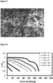
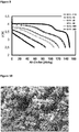
- Figure 8 shows the discharge curves at 1C at room temperature for an electrode containing Li 0.80 Mn 0.80 Fe 0.15 Zn 0.05 PO 4 as active material and in comparison in figure 9 the discharge curves at 1C at room temperature for an electrode containing Li 0.93 Mn 0.80 Fe 0.15 Zn 0.05 PO 4 (SO 4 ) 0.01 as active material.
- SO 4 Li 0.93 Mn 0.80 Fe 0.15 Zn 0.05 PO 4
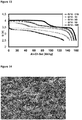
- Figure 12 shows the discharge curves at 1C at room temperature for an electrode containing LiMn 0.61 Fe 0.34 Zn 0.05 PO 4 as active material and in comparison in figure 13 the discharge curves at 1C at room temperature for an electrode containing Li 0.96 Mn 0.61 Fe 0.34 Zn 0.05 PO 4 (SO 4 ) 0.01 as active material.
- SO 4 Li 0.96 Mn 0.61 Fe 0.34 Zn 0.05 PO 4
- Figure 16 shows the discharge curves at 1C at room temperature for an electrode containing Li 0.80 Mn 0.63 Fe 0.34 Zn 0.03 PO 4 as active material and in comparison in figure 17 the discharge curves at 1C at room temperature for an electrode containing Li 0.97 Mn 0.63 Fe 0.34 Zn 0.03 PO 4 (SO 4 ) 0.01 as active material.
- SO 4 Li 0.97 Mn 0.63 Fe 0.34 Zn 0.03 PO 4
Description
- The present invention relates to a novel substituted sulphate containing lithium-manganese-metal phosphate, a process for producing it as well as its use as cathode material in a secondary lithium-ion battery.
- Since the publications by Goodenough et al. (J. Electrochem. Soc., 144, 1188-1194, 1997) there has been significant interest in particular in using lithium iron phosphate as cathode material in rechargeable secondary lithium-ion batteries. Lithium iron phosphate, compared with conventional lithium compounds based on spinels or layered oxides, such as lithium manganese oxide, lithium cobalt oxide and lithium nickel oxide, offers higher safety properties in the delithiated state such as are required in particular for the use of batteries in future in electric cars, electrically powered tools etc.
- Pure lithium iron phosphate material was improved by so-called "carbon coating" (Ravet et al., Meeting of Electrochemical Society, Honolulu, 17 - 31 October 1999,
EP 1 084 182 B1 ), as an increased capacity and power capability of the carbon-coated material are achieved at room temperature (160 mAH/g). - In addition to customary solid-state syntheses (
US 5,910,382 C1 orUS 6,514,640 C1 ), a hydrothermal synthesis for lithium iron phosphate with the possibility of controlling the size and morphology of the lithium iron phosphate particles was disclosed inWO 2005/051840 . - A disadvantage of lithium iron phosphate is in particular its redox couple Fe3+/Fe2+ which has a much lower redox potential vis-à-vis Li/Li+ (3.45 V versus Li/Li+) than for example the redox couple Co3+/Co4+ in LiCoO2 (3.9 V versus Li/Li+) .
- In particular lithium manganese phosphate LiMnPO4 is of interest in view of its higher Mn2+/Mn3+ redox couple (4.1 volt) versus Li/Li+. LiMnPO4 was also already disclosed by
Goodenough et al., US 5,910,382 . - However, the production of electrochemically active and in particular carbon-coated LiMnPO4 has proved to be very difficult.
- The electrochemical properties of lithium manganese phosphate were improved by iron substitution of the manganese sites:
- Herle et al. in Nature Materials, Vol. 3, pp. 147-151 (2004) describe lithium-iron and lithium-nickel phosphates doped with zirconium. Morgan et al. describes in Electrochem. Solid State Lett. 7 (2), A30-A32 (2004) the intrinsic lithium-ion conductivity in LixMPO4 (M = Mn, Fe, Co, Ni) olivines. Yamada et al. in Chem. Mater. 18, pp. 804-813, 2004 deal with the electrochemical, magnetic and structural features of Lix(MnyFe1-y)PO4, which are also disclosed e.g. in
WO2009/009758 . Structural variations of Lix(MnyFe1-y)PO4, i.e. of the lithiophilite-triphylite series, were described by Losey et al. The Canadian Mineralogist, Vol. 42, pp. 1105-1115 (2004). The practical effects of the latter investigations in respect of the diffusion mechanism of deintercalation in Lix(MnyFe1-y)PO4 cathode material are found in Molenda et al. Solid State Ionics 177, 2617-2624 (2006). - In most cases, an increase in specific capacity compared to the pure lithium manganese phosphate upon substitution of iron for manganese in lithium manganese phosphate is observed. However, a plateau-like region occurs for the discharge curves at 3.5 volt vis-à-vis lithium (iron plateau), the length of which compared with pure LiMnPO4 increases as the iron content increases, which results in a loss of energy density compared to an ideal LiMnPO4 that would have the same capacity as a LiFePO4. (see Yamada et al. in the publication mentioned above). The slow kinetics (charge and discharge kinetics) of manganese-containing metal phosphates, in particular Lix(MnyFe1-y)PO4 with y > 0.8, have so far made the use of these compounds for battery applications largely impossible. Compounds like LiMn0.56Fe0.33Zn0.10PO4 or LiMn0.66Fe0.33PO4 have been recently synthesized (
DE 10 2010 006 077 A1 ) and have proven to show good capacity when used as active materials for cathodes in secondary lithium ion batteries. - However, synthesis of these compounds especially via wet chemistry methods or hydrothermal methods yields materials with large primary particles and a high lithium deficiency causing a negative impact such as a relatively low capacity of the related lithium cells.
- The object of the present invention was therefore to provide novel lithium-manganese-metal phosphate compounds which provide a high energy density when used as cathode material and provide further a high redox potential with a rapid kinetics in respect of charge and discharge processes and to avoid a large lithium deficiency in the stoichiometry.
-
FR 2932396 -
US 2010/2977496 discloses a process for preparing carbon-treated complex oxides of formula C-AMXO4 having a very low water content; A represents Li, alone or partially replaced by at most 10% Na or K, M represents Fe(II), alone or partially replaced by at most 50% Mn, Ni or Co, and/or by at most 10% as atoms of one or more aliovalent or isovalent metals other than Mn, Ni and Co, and/or by up to 5% or Fe(III); and XO4 represents PO4 alone or partially replaced by at most 10 mmol% or at least one of SO4 and SiO4. The carbon is deposited by pyrolysis. -
EP 2522625 relates to the preparation of a particulate positive electrode material for lithium iron cells of formula LiMnxFe1-xPO4, wherein x is 0.05-0.5. - The object of the present invention is achieved by a substituted sulphate containing mixed lithium-manganese-metal phosphate of formula
LixFeyMn1-yM1-(y+z)(PO4)u(SO4)v
wherein - M is a metal selected from the group Co, Ni, Al, Mg, Sn, Pb, Nb ,B, Cu, Cr, Mo, Ru, V, Ga, Ca, Sr, Ba, Ti, Zr, Cd and mixtures thereof
- Surprisingly it was found that the sulphate containing mixed lithium-manganese-metal phosphate compound(s) (or in the following "the material(s)") according to the invention have a higher specific capacity than sulphate free lithium manganese iron phosphates and have a very low lithium deficiency if at all as well as a small primary particle size.
- The increase in specific capacity is in the range of about 5 to 15 % compared corresponding to prior art materials without the presence of sulphate. The total sulphur content as measured by ICP is in the range between 0.01 and 0.16 wt% based on the total material weight. The material according to the invention has a controlled stoichiometry even a small Li deficiency can be controlled and regulated according to the specific electronic properties of the material.
- The lithium-manganese-metal phosphate according to the invention may be doped or non-doped.
- The term "a or the lithium-manganese-metal phosphate" means within the scope of this invention therefore that the lithium-manganese-metal phosphate is present both doped or non-doped.
- "Non-doped" means pure, in particular phase-pure lithium-manganese-metal phosphate having the formula LixFeyMn1-y(PO4)u(SO4)v wherein x, y, u and v have the same meanings as above.
- "Doped" lithium-manganese-metal phosphate denotes a compound of the formula LixFeyMn1-yM1-(y+z)(PO4)u(SO4)v with x, y, u, z and v as defined before, wherein an additional metal M is present.
- As recited above M may be selected from the group consisting of Co, Ni, Al, Mg, Sn, Pb, Nb ,B, Cu, Cr, Mo, Ru, V, Ga, Ca, Sr, Ba, Ti, Zr, Cd and mixtures thereof. Preferably M represents Co, Mg, Nb, Ni, Al, Zn and mixtures thereof and (y+z) has a value of being ≤ 0.5 and ≥ 0.001. Exemplary stoichiometric formulae are LixFeyMn1-yMg1-(y+z)(PO4)u(SO4)v, LixFeyMn1-yNb1-(y+z)(PO4)u(SO4)v, LixFeyMn1-yCo1-(y+z)(PO4)u(SO4)v, LixFeyMn1-yZn1-(y+z)(PO4)u(SO4)v and LixFeyMn1-yAl1-(y+z)(PO4)u(SO4)v, LixFeyMn1-y(Zn,Mg)1-(y+z)(PO4)u(SO4)v with x, y, z, u and v having the same meanings as recited above.
- In further embodiments of the invention, the metal M represents Zn, Mg, Al or combinations thereof like (Zn, Mg), (Mg, Al) or (Zn, Al), in particular M is Zn. It has been surprisingly found that these electrochemically inactive dopants provide materials according to the invention with particularly high energy density and capacity compared to the non-doped materials according to the invention or to materials doped with other dopants when they are used as electrode materials.
- In one embodiment of the substituted sulphate containing lithium-manganese-metal phosphate of the present invention LixFeyMn1-yM1-(y+z)(PO4)u(SO4)v, the value for [1-(y+z)] is in the range of more than 0.02 to 0.20 and is 0.03, 0.05, 0.06, 0.07 and 0.1 in specific embodiments.
- The amount of sulphate is in the range of 0 < v ≤ 0.25, preferably between 0 < v ≤ 0.012. Too much sulphate would result in a loss of Li-ion conductivity. The specific embodiments v is 0.006 or 0.010.
- The substitution (or doping) by the metal cations that are in themselves electrochemically inactive seems to provide the very best results at values of 1-(y+z) = 0.03 - 0.15 ± 0.01, preferably 0.03 - 0.1 ± 0.01 with regard to energy density and capacity of the material according to the invention. Further specific embodiments are even values for [1-(y+z)] in the aforementioned ranges such as 0.05, 0.06, 0.07, 0.08, 0.09 and 0.1 ± 0.01. It was found that a high manganese content with a relatively low iron content (i.e. more manganese than iron should be present) and a relatively high zinc and/or magnesium (or aluminium) content provide the best results in respect of energy density, which is particularly surprising in view of the electrochemically inactive character of magnesium and zinc. It was found that for compounds according to the invention such as Li0.9Mn0.80Fe0.10Zn0.10(PO4)(SO4)0.01, Li0.95Mn0.56Fe0.34Zn0.10(PO4)(SO4)0.01 and Li0.95Mn0.59Fe0.34Zn0.07(PO4)(SO4)0.01 and LiMn0.56Fe0.33Zn0.10(PO4)(SO4)0.01 the 4V plateau is longer than for Li0.95Mn0.59Fe0.34Zn0.07PO4 or Li0.80Mn0.56Fe0.33Zn0.10PO4 and the specific capacity is higher, which means an increase in energy density.
- In further embodiments of the present invention, the value for y in the mixed lithium-manganese-metal phosphate according to the invention is 0.05 - 0.4, preferably 0.1 - 0.4. Exemplary specific values are preferably 0.10 ± 0.015, 0.15 ± 0.015, 0.20 ± 0.015, and in particular 0.33 and 0.34 ± 0.15, specifically 0.35 ± 0.015. These values, in particular in conjunction with the above-mentioned values for 1-(y+z) represent the most preferred compromise between energy density and rate capability of the material according to the invention.
- This means that for example the compound Li0.95Mn0.59Fe0.34Zn0.07(PO4)(SO4)0.01 has a good rate capability up to 20C during discharge comparable with that of LiFePO4 of the state of the art (e.g. available from Clariant Produkte (Deutschland) GmbH or Phostech Lithium Inc.), but in addition also an increase in energy density (approx. 15-% vis-à-vis LiFePO4 (measured against a lithium anode).
- In embodiments of the invention, the atomic ratio Li/∑Fe+Mn+M is in the range of between 0.9 to 1.5 (which corresponds to the value of x). It has been found that mixed lithium-manganese-metal phosphates satisfying this requirement provide an especially high capacity. In further embodiments this value is in the range of 0.9 to 1.2.
- In further embodiments of the present invention, the substituted sulphate containing lithium-manganese-metal phosphate compounds also comprise carbon. The carbon is particularly preferably evenly distributed throughout the substituted lithium-manganese-metal phosphate. In other words, the carbon forms a type of matrix in which the lithium-manganese-metal phosphate according to the invention is embedded. It makes no difference for the meaning of the term "matrix" used here whether e.g. the carbon particles serve as "nucleation sites" for the LixFeyMn1-yM1-(y+z)(PO4)u(SO4)v according to the invention, i.e. whether these nucleate on the carbon, or whether, as in a particularly preferred development of the present invention, the individual particles of the lithium-manganese-metal phosphate LixFeyMn1-yM1-(y+z)(PO4)u(SO4)v are covered in carbon, i.e. sheathed or in other words at least partially coated. Both variants are considered as equivalent according to the invention and fall under the above definition of the term "carbon comprising".
- Important for the purpose of the present invention is merely that the carbon is evenly distributed in the substituted lithium-manganese-metal phosphate LixFeyMn1-yM1-(y+z)(PO4)u(SO4)v according to the invention and forms a type of (three-dimensional) matrix. In embodiments of the present invention, the presence of carbon or a carbon matrix can make obsolete the further addition of electrically conductive additives such as e.g. conductive carbon black, graphite etc. when using the LixFeyMn1-yM1-(y+z)(PO4)u(SO4)v according to the invention as electrode material.
- In a further embodiment of the invention, the proportion of carbon relative to the substituted lithium-manganese-metal phosphate is ≤ 4 wt.-%, in further embodiments ≤ 2.5 wt.-%, in still further embodiments ≤ 2.2 wt.-% and in still further embodiments ≤ 2.0 wt.-%. Thus the best energy densities of the material according to the invention are achieved.
- The sulphate containing lithium-manganese-metal phosphate LixFeyMn1-yM1-(y+z)(PO4)u(SO4)v according to the invention is preferably contained as active material in a cathode for a secondary lithium-ion battery. As stated, this cathode can also contain the LixFeyMn1-yM1-(y+z)(PO4)u(SO4)v according to the invention without further addition of a further conductive material such as e.g. conductive carbon black, acetylene black, Ketjen black, graphite etc. (in other words is free of added conductive agent), both in the case of the carbon-containing LixFeyMn1-yM1-(y+z)(PO4)u(SO4)v according to the invention and the carbon-free LixFeyMn1-yM1-(y+z)(PO4)u(SO4)v.
- In further preferred embodiments, the cathode according to the invention contains a further lithium-metal-oxygen compound. This addition increases the energy density by up to approx. 10 - 15%, depending on the type of the further mixed lithium metal compound compared with cathodes which contain only the LixFeyMn1-yM1-(y+z)(PO4)u(SO4)v according to the invention as the sole active material.
- The further lithium-metal-oxygen compound is preferably selected from substituted or non-substituted LiCoO2, LiMn2O4, Li1+x(Ni,Mn,Co)1-xO2, Li(Ni,Co,Al)O2 and LiNiO2, as well as Li(Mn,Fe)PO4, LiFePO4, LiCoPO4, LiNiPO4 and mixtures thereof.
- The object of the present invention is further achieved by a process for producing a mixed lithium-manganese-metal phosphate according to the invention with the general formula LixFeyMn1-yM1-(y+z)(PO4)u(SO4)v comprising the following steps:
- a. providing an aqueous mixture with a pH < 7.5 containing at least one Li starting compound, one Mn starting compound, one Fe starting compound, optionally one M starting compound, one PO4 3- and one SO4 2- starting compound until a precipitate or a suspension in aqueous solution forms,
- b. carrying out a dispersion or grinding treatment of the mixture and/or the suspension,
- c. obtaining LixFeyMn1-yM1-(y+z)(PO4)u(SO4)v wherein x, y, z and v have the above referenced meanings, from the suspension by reaction under hydrothermal conditions wherein a precipitate forms.
- The treatment in step b. is preferably carried out until the D90 value of the particles in the mixture is less than 50 µm, preferably at most 25 µm.
- The term "hydrothermal conditions" means for the purpose of the present invention temperatures of 100°C to 200°C, preferably 100°C to 170°C and quite particularly preferably 120°C to 170°C as well as a pressure of 1 bar to 40 bar vapour pressure. In particular, it has surprisingly been shown that the synthesis at the quite particularly preferred temperature of 120 - 170°C, in particular at 160 ± 5°C, leads to an increase in the specific capacity of the thus-obtained LixFeyMn1-yM1-(y+z)(PO4)u(SO4)v according to the invention compared with reaction at more than 170°C.
- As stated before, the synthesis takes place in aqueous solution/suspension. At the end of the reaction, the pH of the reaction solution (i.e. after precipitation of the product LixFeyMn1-yM1-(y+z)(PO4)u(SO4)v) is approx. 5 to 6.5, i.e. the reaction itself takes place in a non-basic or in other words in a weak acid environment.
- The process according to the invention makes possible in particular the production of phase-pure LixFeyMn1-yM1-(y+z)(PO4)u(SO4)v, which means free of impurities to be determined by means of XRD.
- Also disclosed is the provision of LixFeyMnx-yM1-(y+z)(PO4)u(SO4)v which can be obtained by means of the process according to the invention and is compared to a solid state synthesis pathway phase-pure in the sense as mentioned before, i.e. especially no phosphide phases can be detected in the final product.
- In embodiments of the process according to the invention, the dispersion or grinding treatment begins before or during the suspension formation and is continued until the suspension/precipitation is finished.
- Preferably, the dispersion or grinding treatment starts before the suspension/precipitation of the mixture in order to bring about an increased nucleation and in order to prevent the formation of large crystals and crystal agglomerates.
- After the hydrothermal treatment, the LixFeyMn1-yM1-(y+z)(PO4)u(SO4)v obtained according to the invention is separated off by filtration and/or centrifuging as well as dried and, in preferred embodiments of the invention, disagglomerated in order to obtain a product consisting predominantly (ca. 95%) of primary particles, e.g. by grinding with an air-jet mill.
- In specific embodiments of the process according to the invention, a carbon-containing material is added during step a) or c). This can be either pure carbon, such as e.g. graphite, acetylene black or Ketjen black, or a carbon-containing precursor compound which then decomposes when exposed to the action of heat to a carbonaceous residue, e.g. starch, gelatine, a polyol, a sugar such as mannose, fructose, sucrose, lactose, galactose, a partially water-soluble polymer such as e.g. a polyacrylate etc.
- Alternatively, the LixFeyMn1-yM1-(y+z)(PO4)u(SO4)v obtained after the hydrothermal treatment can also be mixed with a carbon-containing material as defined above or impregnated with an aqueous solution of same. This can take place either directly after the isolation (filtration) of the LixFeyMn1-yM1-(y+z)(PO4)u(SO4)v or after it has been dried or disagglomerated.
- For example the mixture of LixFeyMn1-yM1-(y+z)(PO4)u(SO4)v and a carbon precursor compound (which was added e.g. during the process) or the LixFeyMn1-yM1-(y+z)(PO4)u(SO4)v impregnated with for a solution the carbon precursor compound (as for example sucrose or lactose) is then dried and heated at a temperature between 500°C and 850°C, wherein the carbon precursor compound is pyrolyzed to pure carbon which then wholly or at least partly covers the LixFeyMn1-yM1-(y+z)(PO4)u(SO4)v particles as a layer (coating).
- The pyrolysis can be followed by a grinding or disagglomeration treatment but the grinding step is not mandatory.
- The LixFeyMn1-yM1-(y+z)(PO4)u(SO4)v obtained according to the process invention is preferably dried under protective gas, in air or under vacuum at temperatures of from 50°C to 200°C, preferably under protective gas and the pyrolysis preferably likewise under protective gas, preferably nitrogen.
- Within the scope of the process according to the invention, the at least one Li+ source, the Fe2+ and Mn2+ sources as well as the My+ (y = 2, 3 or 4; for Nb and V, Mo y may be also 5) source(s) are preferably used in the form of aqueous solutions and the PO4 3- and SO4 2- sources in the form of a liquid, e.g. as H3PO4 or H2SO4 or as an aqueous solution or suspension of a solid phosphate and/or sulphate compound.
- In preferred embodiments of the process according to the invention, the Li+ source is first dissolved in an aqueous solvent, the Fe2+, the Mn2+ and the My+ sources as well as the PO4 3- and SO4 2- source are then added and mixed under inert gas atmosphere. The reaction then takes place under hydrothermal conditions and preferably under protective gas.
- According to the invention, Li2O, LiCl, LiNO3, LiOH, Li2SO4 or Li2CO3, preferably LiOH, Li2O, Li2SO4 or Li2CO3, is used as lithium source.
- In further embodiments of the invention a second lithium source is used which is different from the first one. Preferably the second lithium source is Li2SO4 providing a cheap and simple source for sulphate consisting from the waste water when the process according to the invention is designed as a cyclic process as for example described in
WO2006/097324 orWO2009/010263 . If the first lithium source is already Li2SO4, then it is evident that the second one is not Li2SO4 but for example LiOH, Li2O ect. - The Fe source is preferably an Fe2+ salt, in particular FeSO4, FeCl2, FeNO3, Fe3(PO4)2 or an Fe organyl salt or an iron carboxylate like iron oxalate, iron citrate, iron acetate etc.
- The Mn source is preferably a water-soluble manganese (II) salt such as manganese sulphate, manganese acetate, manganese oxalate, manganese chloride, manganese nitrate, manganese hydroxide, manganese carbonate etc.
- According to the invention, phosphoric acid, a metal phosphate, hydrogen phosphate or dihydrogen phosphate is preferably used as PO4 3- source.
- In particular, the corresponding sulphates, in particular of Mg, Zn and Ca, or the corresponding halides, nitrates, acetates, carboxylates, preferably the acetates and caboxylates may be used as source for the bivalent metal cation.
- The invention is explained in more detail below with reference to examples and drawings which are not, however, to be considered as limiting the scope of the invention.
- It is shown in:
- Figure 1
- discharge curves at 1C and at room temperature for Li0.80Mn0.56Fe0.33Zn0.10PO4 (Comparative Example 1);
- Figure 2
- discharge curves at 1C and at room temperature for Li0.99Mn0.56Fe0.33Zn0.10PO4(SO4)0.006 (Example 1) ;
- Figure 3
- discharge curves at 1C and at room temperature for Li0.99Mn0.56Fe0.33Zn0.10PO4 (SO4) 0.01 (Example 2) ;
- Figure 4
- discharge curves for at 1C at room temperature for Li0.80Mn0.59Fe0.34Zn0.07PO4;
- Figure 5
- discharge curves for at 1C at room temperature for Li0.91Mn0.59Fe0.34Zn0.07PO4(SO4)0.01;
- Figure 6
- SEM image of Li0.80Mn0.59Fe0.34Zn0.07PO4;
- Figure 7
- SEM image of Li0.91Mn0.59Fe0.34Zn0.07PO4(SO4)0.01
- Figure 8
- discharge curves at 1C at room temperature for Li0.80Mn0.80Fe0.15Zn0.05PO4
- Figure 9
- discharge curves at 1C at room temperature for Li0.93Mn0.80Fe0.15Zn0.05PO4(SO4)0.01
- Figure 10
- SEM image of Li0.80Mn0.80Fe0.15Zn0.05PO4
- Figure 11
- SEM image of LiMn0.80Fe0.15Zn0.05PO4(SO4)0.01
- Figure 12
- discharge curves at 1C at room temperature for LiMn0.61Fe0.34Zn0.05PO4
- Figure 13
- discharge curves at 1C at room temperature for Li0.96Mn0.61Fe0.34Zn0.05PO4(SO4)0.01
- Figure 14
- SEM image of Li0.80Mn0.61Fe0.34Zn0.05PO4
- Figure 15
- SEM image of Li0.96Mn0.61Fe0.34Zn0.05PO4(SO4)0.01
- Figure 16
- discharge curves at 1C at room temperature for Li0.80Mn0.63Fe0.34Zn0.03PO4
- Figure 17
- discharge curves at 1C at room temperature for Li0.97Mn0.63Fe0.34Zn0.03PO4(SO4)0.01
- The particle-size distributions for the mixtures or suspensions and of the produced material is determined using the light scattering method using commercially available devices. This method is known per se to a person skilled in the art, wherein reference is also made in particular to the disclosure in
JP 2002-151082 WO 02/083555 - The D90 value gives the value at which 90% of the particles in the measured sample have a smaller or the same particle diameter. Accordingly, the D50 value and the D10 value give the value at which 50% and 10% respectively of the particles in the measured sample have a smaller or the same particle diameter.
- According to an embodiment according to the invention, the values mentioned in the present description are valid for the D10 values, D50 values, the D90 values as well as the difference between the D90 and D10 values relative to the volume proportion of the respective particles in the total volume. Accordingly, the D10, D50 and D90 values mentioned herein give the values at which 10 volume-% and 50 volume-% and 90 volume-% respectively of the particles in the measured sample have a smaller or the same particle diameter. If these values are obtained, particularly advantageous materials are provided according to the invention and negative influences of relatively coarse particles (with relatively larger volume proportion) on the processability and the electrochemical product properties are avoided. Preferably, the values mentioned in the present description are valid for the D10 values, the D50 values, the D90 values as well as the difference between the D90 and the D10 values relative to both percentage and volume percent of the particles.
- For compositions (e.g. electrode materials) which, in addition to the lithium-manganese iron phosphates according to the invention are further doped with metal cations, contain further components, in particular for carbon-containing compositions, the above light scattering method can lead to misleading interpretations as the primary particles can form agglomerates within the suspension. However, the primary particle-size distribution of the material according to the invention can be directly determined as follows for such compositions using SEM photographs:
- A small quantity of the powder sample is suspended in acetone and dispersed with ultrasound for 10 minutes. Immediately thereafter, a few drops of the suspension are dropped onto a sample plate of a scanning electron microscope (SEM). The solids concentration of the suspension and the number of drops are measured so that a large single-ply layer of powder particles forms on the support in order to prevent the powder particles from obscuring one another. The drops must be added rapidly before the particles can separate by size as a result of sedimentation. After drying in air, the sample is placed in the measuring chamber of the SEM. In the present example, this is a LEO 1530 apparatus which is operated with a field emission electrode at 1.5 kV excitation voltage and a 4 mm space between samples. At least 20 random sectional magnifications of the sample with a magnification factor of 20,000 are photographed. These are each printed on a DIN A4 sheet together with the inserted magnification scale. On each of the at least 20 sheets, if possible at least 10 free visible particles of the material according to the invention, from which the powder particles are formed together with the carbon-containing material, are randomly selected, wherein the boundaries of the particles of the material according to the invention are defined by the absence of fixed, direct connecting bridges. On the other hand, bridges formed by carbon material are included in the particle boundary. Of each of these selected particles, those with the longest and shortest axis in the projection are measured in each case with a ruler and converted to the actual particle dimensions using the scale ratio. For each measured particle, the arithmetic mean from the longest and the shortest axis is defined as particle diameter. The measured particles are then divided analogously to the light-scattering method into size classes. The differential particle-size distribution relative to the number of particles is obtained by plotting the number of the associated particles in each case against the size class. The cumulative particle-size distribution from which D10, D50 and D90 can be read directly on the size axis is obtained by continually totalling the particle numbers from the small to the large particle classes.
- The described process was also applied to battery electrodes containing the material according to the invention. In this case, however, instead of a powder sample a fresh cut or fracture surface of the electrode is secured to the sample holder and examined under a SEM.
- When producing the materials, it is to be borne in mind that the materials are precipitated from an aqueous Fe2+ precursor solution. The reaction and drying/sintering is therefore preferably to be carried out under protective gas or vacuum in order to avoid a partial oxidation of Fe2+ to Fe3+ with formation of by-products such as Fe2O3 or FePO4.
- First, 105.5 g lithium hydroxide LiOH · H2O was dissolved in 0.9 1 distilled water. This solution is called basic solution. 77.43 g FeSO4 x 7 H2O, 79.88 g MnSO4 x H2O and 24.27 g ZnSO4 x 7 H2O were dissolved in approx. 1.5 1 distilled water and 103.38 g 80-% phosphoric acid added slowly accompanied by stirring. 0.4 1 distilled wash water was added. This solution is termed acid solution.
- The basic solution was introduced into the laboratory autoclave (capacity: 4 litres) at 600 rpm stirrer speed, the autoclave loaded with approx. 6 - 7 bar nitrogen via the dipping tube and relieved again via the vent valve. The procedure was repeated three times.
- A disperser (IKA, ULTRATURRAX® UTL 25 Basic Inline with dispersion chamber DK 25.11) was connected to the autoclave between vent valve and bottom outlet valve in order to carry out the dispersion or grinding treatment. The pumping direction of the disperser was bottom outlet valve - disperser - vent valve. The disperser was started on the middle power level (13,500 rpm) according to the manufacturer's instructions.
- The prepared acid solution was then pumped with a membrane pump via the dipping tube into the autoclave (
stroke 100%, 180 strokes/minute; corresponds to the maximum capacity of the pump) and reflushed with approx. 500 to 600 ml distilled water. The pumping-in lasted for approx. 20 minutes, wherein the temperature of the resultant suspension increased to approx. 40°C. After pumping-in of the acid solution, a deposit precipitated out. - The disperser, which was started before the addition of the acid solution, was used for a total of approx. 1 hour for intensive mixing or grinding of the resultant, viscous suspension (after pumping-in of the acid solution at 50°C).
- The use of a disperser brings an intensive mixing and the agglomeration of the precipitated viscous pre-mixture. During the precipitation and crystallization of the suspension, a homogeneous mixture of many small, approximately equally-sized crystal nuclei formed in the disperser as a result of the pre-grinding or intensive mixing. These crystal nuclei crystallized during the subsequent hydrothermal treatment (see below) to very uniformly grown crystals of the end-product with a very narrow particle-size distribution. The power and energy input via the dispersion treatment was respectively more than 7 kW/m3 and more than 7 kWh/m3 of the treated precursor mixture/suspension.
- Each freshly produced suspension was subjected to hydrothermal treatment in the laboratory autoclave. Before heating the suspension, the autoclave was flushed with nitrogen in order to expel any air present from the autoclave before the hydrothermal process. The product according to the invention formed starting from hydrothermal temperatures of approximately 100 to 120°C. The hydrothermal treatment was preferably carried out for 2 hours at 130°C.
- After switching off and disconnecting the disperser the mixture was heated over 1.5 hours to 130°C, for 2 hours. Cooling to 30°C then took place over 3 hours.
- LiMn0.56Fe0.33Zn0.10PO4 was then dried in air or in the drying oven for example at mild temperatures (40°C) without visible oxidation. The atomic ratio Li/∑Fe+Mn+M was 0.85 indicating a lithium deficiency.
- The thus-obtained material was pumped under nitrogen atmosphere through the bottom outlet valve of the autoclave into a pressure filter (Seitz filter). The membrane pump setting was such that a pressure of 5 bar was not exceeded. The filter cake was subsequently washed with distilled water until the conductivity of the wash water had fallen below 42 µS/cm.
- The synthesis was carried out as in Example 1, except that 20.80 g MgSO4*7 H2O was used as starting material in the corresponding molar weight quantities instead of ZnSO4. The atomic ratio Li/∑Fe+Mn+M was 0.87 indicating a lithium deficiency.
- The synthesis was carried out as in Example 1, except that 114.12 g MnSO4*1 H2O, 23.46 g FeSO4*7 H2O, 24.27 g ZnSO4*7 H2O, 103.38 g H3PO4, (80%) were used as starting materials in the corresponding molar weight quantities. The atomic ratio Li/∑Fe+Mn+M was 0.78 indicating a lithium deficiency.
- The synthesis was carried out as in Example 1, except that 121.26 g MnSO4*1 H2O, 23.46 g FeSO4*7 H2O, 12.14 g ZnSO4*7 H2O, 103.38 g H3PO4 (80%) were used as starting materials in the corresponding molar weight quantities. The atomic ratio Li/∑Fe+ Mn+M was 0.82 indicating a lithium deficiency.
- The synthesis was carried out according to comparative example 1 with the difference that additionally 100 ml of a 0.1 m solution of Li2SO4 was added to the starting materials to obtain the desired stoichiometry. The atomic ratio Li/∑Fe+Mn+M was 0.99 indicating no lithium deficiency.
- The synthesis was carried out according to comparative example 1 with the difference that additionally 100 ml of a 0.1 m solution of Li2SO4 was added to the starting materials to obtain the desired stoichiometry. The atomic ratio Li/∑Fe+Mn+M was 0.99 indicating no lithium deficiency.
- The following materials (with the atomic ratio Li/∑Fe+Mn+M determined by ICP-OES measurements (Varian Vista Pro 720 ES) were synthesized according to example 1 but varying the amounts of the lithium sulphate solution.
- LixMn0.56Fe0.33Zn0.10PO4(SO4)0.01 (atomic ratio Li/∑Fe +Mn+M: 0.937), LixMn0.59Fe0.34Zn0.07PO4(SO4)0.01 ((atomic ratio Li/∑Fe+Mn+M: 0.911); LixMn0.80Fe0.15Zn0.05PO4(SO4)0.01 (atomic ratio Li/∑Fe+Mn+M: 0.930); LixMn0.61Fe0.34Zn0.05PO4(SO4)0.01 (atomic ratio Li/∑Fe+Mn+M: 0.964) LixMn0.63Fe0.34Zn0.03PO4(SO4)0.01 (atomic ratio Li/∑Fe+Mn+M: 0.972); LixMn0.59Fe0.34Zn0.07PO4(SO4)0.006 (atomic ratio Li/∑Fe+Mn+M: 0.945); LixMn0.80Fe0.15Zn0.05PO4(SO4)0.006 (atomic ratio Li/∑Fe+Mn+M: 0.973); LixMn0.61Fe0.34Zn0.05PO4(SO4)0.006 (atomic ratio Li/∑Fe+Mn+M: 0.981) LixMn0.63Fe0.34Zn0.03PO4(SO4)0.006 (atomic ratio Li/∑Fe+Mn+M: 0.922)
- The filter cakes obtained in Examples 1 to 4 were impregnated with a solution of 24 g lactose in water and then calcined at 750°C for 3 hours under nitrogen.
- Depending on the quantity of lactose, the proportion of carbon in the product according to the invention was between 0.2 and 4 wt.-%.
- Typically 1 kg dry product from Examples 1 and 2 was mixed intimately with 112 g lactose monohydrate and 330 g deionized water and dried overnight in a vacuum drying oven at 105°C and < 100 mbar to a residual moisture of 3%. The brittle drying product was broken by hand and coarse-ground in a disk mill (Fritsch Pulverisette 13) with a 1 mm space between disks and transferred in high-grade steel cups into a protective gas chamber furnace (Linn KS 80-S). The latter was heated to 750°C within 3 hours at a nitrogen stream of 200 l/h, kept at this temperature for 3 hours and cooled over 3 hours to room temperature. The carbon-containing product was disagglomerated in a jet mill (Hosokawa).
- The SEM analysis of the particle-size distribution produced the following values: D50 < 0.5 µm, difference between D90 and D10 value: < 1 µm.
- The synthesis of the materials according to the invention was carried out as in Examples 1 to 4, except that gelatine was also then added (9 g gelatine per 100 g starting product) during the precipitation step a). The end-product contained approx. 2.3 wt.-% carbon.
- Thin-film electrodes as disclosed for example in Anderson et al., Electrochem. and Solid State Letters 3 (2) 2000, pages 66-68 were produced. The electrode compositions usually consisted of 90 parts by weight active material, 5 parts by weight Super P carbon and 5-% polyvinylidene fluoride as binder or 80 parts by weight active material, 15 wt.-% Super P carbon and 5 parts by weight polyvinylidene fluoride, or 95 parts by weight active material and 5 parts by weight polyvinylidene fluoride.
- The active material was mixed, together with the binder (or, for the electrodes of the state of the art, with the added conductive agent), in N-methylpyrrolidone, applied to a pretreated (primer) aluminium foil by means of a doctor blade and the N-methylpyrrolidone was evaporated at 105°C under vacuum. The electrodes were then cut out (13 mm diameter) and roll-coated with a roller at room temperature. The starting nip width was e.g. 0.1 mm and the desired electrode thickness progressively adjusted in steps of 5-10 µm. 4 rolled coats were applied at each step and the foil was rotated by 180°. After this treatment, the thickness of the coating was between 20-25µm. The primer on the aluminium foil consisted of a thin carbon coating which improves the adhesion of the active material particularly when the active material content of the electrode is more than 85 wt.-%.
- The electrodes were then dried overnight at 120°C under vacuum. Half cells were assembled in an argon-filled glovebox and were subsequently electrochemically measured..
- The electrochemical measurements were carried out against lithium metal and using LP30 (Merck, Darmstadt) as electrolyte (EC (ethylene carbonate):DMC (dimethylcarbonate) = 1:1, 1 M LiPF6).
- The charge procedure was carried out in CCCV mode, i.e. cycles with a constant current at the C/10 rate followed by a constant voltage portion at the voltage limits (4.3 volt versus Li/Li+) until the current fell approximately to the C/100 rate, in order to complete the charge.
- Corresponding measurements of the specific capacity and the current carrying capacity were carried out on both Lix(Mn0.66Fe0.33)PO4 of the state of the art and materials according to the invention substituted with magnesium and zinc.
-
Figure 1 shows the discharge curves at 1C and at room temperature for an electrode containing Li0.80Mn0.56Fe0.33Zn0.10PO4 (Comparative Example 1) as active material. The ratio Li/∑Fe+Mn +M was 0.8 which is an indicator for Li deficiency. The specific energy was measured to 446 mWh/g, the press density 1.51 g/cm3 and the volumetric energy 673 mWh/cm3. After several cycles, aloss of specific capacity was recorded in the range of 15 to 40 mAh/g. -
Figure 2 shows the discharge curves at 1C and at room temperature for an electrode containing Li0.99Mn0.56Fe0.33Zn0.10PO4(SO4)0.006 (Example 1) as active material andFigure 3 the discharge curves at 1C and at room temperature for an electrode containing Li0.99Mn0.56Fe0.33Zn0.10PO4(SO4)0.01 (Example 2) as active material. Compared to the material shown inFigure 1 representing state of the art the energy loss upon cycling is remarkably diminished. Both samples show basically no Li deficiency (Example 1 and Example 2 both have a Li/∑Fe+Mn+M ratio of 0.99. The specific energy for the electrode with Li0.99Mn0.56Fe0.33Zn0.10PO4 (SO4) 0.006 as active material was measured as 522 mWh/g for the electrode with Li0.99Mn0.56Fe0.33Zn0.10PO4 (SO4) 0.01 as active material to 527 mWH/g, i.e. remarkably higher than with the electrode of the prior art shown infigure 1 . The same improvement was observed for the press density (1.86 g/cm3 and 2.15 g/cm3 respectively) and the volumetric energy (970 mWh/cm3 and 1133 mWh/cm3 respectively). -
Figure 4 shows the discharge curves at 1C at room temperature for an electrode with Li0.80Mn0.59Fe0.34Zn0.07PO4 as active material and in comparison -
Figure 5 the discharge curves at 1C at room temperature for an electrode containing Li0.91Mn0.59Fe0.34Zn0.07PO4(SO4)0.01 as active material. After several cycles it was observed that the energy loss upon cycling is remarkably diminished for the material Li0.91Mn0.59Fe0.34Zn0.07PO4(SO4)0.01 according to the invention compared to the prior art material LiMn0.59Fe0.34Zn0.07PO4. The values for specific energy were determined as 525 mWH/g to 595 mWH/g showing the better performance of the material according to the invention. The same observation was made for the parameters press density (1.63 g/cm3 to 1.64 g/cm3) and volumetric energy (855 mWh/cm3 to 975 mWh/cm3). - Comparing the physical appearance (SEM images) of the particles of Li0.80Mn0.59Fe0.34Zn0.07PO4 in
figure 6 with Li0.91Mn0.59Fe0.34Zn0.07PO4(SO4)0.01 infigure 7 it was observed that the particles of Li0.91Mn0.59Fe0.34Zn0.07PO4(SO4)0.01 are slightly more finely grained and have a more regular shape than those of LiMn0.59Fe0.34Zn0.07PO4. -
Figure 8 shows the discharge curves at 1C at room temperature for an electrode containing Li0.80Mn0.80Fe0.15Zn0.05PO4 as active material and in comparison infigure 9 the discharge curves at 1C at room temperature for an electrode containing Li0.93Mn0.80Fe0.15Zn0.05PO4(SO4)0.01 as active material. The same trend as observed beforehand was also observed for this material: - The values for specific energy were determined as 437 mWH/g to 575 mWH/g showing the better performance of the material according to the invention. The same observation was made for the parameters press density (1.70 g/cm3 to 1.72 g/cm3) and volumetric energy (751 mWh/cm3 to 978 mWh/cm3). The SEM images for both products are shown in
figure 10 (Li0.80Mn0.80Fe0.15Zn0.05PO4) andfigure 11 (LiMn0.80Fe0.15Zn0.05PO4(SO4)0.01) with the same conclusion as beforehand. -
Figure 12 shows the discharge curves at 1C at room temperature for an electrode containing LiMn0.61Fe0.34Zn0.05PO4 as active material and in comparison infigure 13 the discharge curves at 1C at room temperature for an electrode containing Li0.96Mn0.61Fe0.34Zn0.05PO4(SO4)0.01 as active material. The same trend as observed beforehand was also observed for this material: - The values for the specific energy were determined as 446 mWH/g to 595 mWH/g showing the better performance of the material according to the invention. The same observation was made for the volumetric energy (856 mWh/cm3 to 1011 mWh/cm3) whereas the press density (1.92 g/cm3 to 1.70 g/cm3) showed an inverse effect compared to the other materials discussed beforehand. The SEM images for both products are shown in
figure 14 (Li0.80Mn0.61Fe0.34Zn0.05PO4) andfigure 15 (Li0.96Mn0.61Fe0.34Zn0.05PO4(SO4)0.01) with the same conclusion as above. -
Figure 16 shows the discharge curves at 1C at room temperature for an electrode containing Li0.80Mn0.63Fe0.34Zn0.03PO4 as active material and in comparison infigure 17 the discharge curves at 1C at room temperature for an electrode containing Li0.97Mn0.63Fe0.34Zn0.03PO4(SO4)0.01 as active material. The same trend as observed beforehand was also observed for this material: - The values for the specific energy were determined as 436 mWH/g to 575 mWH/g showing the better performance of the material according to the invention. The same observation was made for the volumetric energy (785 mWh/cm3 to 1040 mWh/cm3) and the press density (1.80 g/cm3 to 1.81 g/cm3).
Claims (14)
- Mixed Lithium-manganese-metal phosphate of formula
LixFeyMn1-yM1-(y+z)(PO4)u(SO4)v
whereinM is a metal selected from the group Co, Ni, Al, Mg, Sn, Pb, Nb,B, Cu, Cr, Mo, Ru, V, Ga, Ca, Sr, Ba, Ti, Zr, Cd and mixtures thereofand wherein:
- Mixed Lithium-manganese-metal phosphate according to claim 1, wherein M is selected from Co, Mg, Nb, Ni, Al, Zn and mixtures thereof.
- Mixed Lithium-manganese-metal phosphate according to claim 2, wherein M is Zn or Mg or mixtures thereof.
- Mixed Lithium-manganese-metal phosphate according to one of claims 1 to 3, wherein the atomic ratio Li/∑Fe+Mn+M is in the range between 0.9 to 1.5.
- Mixed Lithium-manganese-metal phosphate according to one of the previous claims, further comprising carbon.
- Lithium-manganese-metal phosphate according to claim 5, wherein carbon is evenly distributed throughout the mixed Lithium-manganese-metal phosphate and/or the individual particles of the mixed lithium-manganese-metal phosphate are partially or entirely coated with carbon.
- Lithium-manganese-metal phosphate according to one of claims 5 to 7, wherein the amount of carbon relative to the substituted lithium-manganese-metal phosphate is ≤ 4 wt.-%.
- Cathode for a secondary lithium-ion battery containing a lithium-manganese-metal phosphate according to one of claims 1 to 7.
- Cathode according to claim 8, which is free of added conductive agents.
- Process for producing a mixed lithium-manganese-metal phosphate according to one of the previous claims 1 to 7, comprising the following steps:a. providing an aqueous mixture with a pH < 7,5 containing at least one Li starting compound, one Mn starting compound, one Fe starting compound, optionally one M starting compound, one PO4 3- and one SO4 2- starting compound until a precipitate or suspension forms,b. carrying out a dispersion or grinding treatment of the mixture and/or the suspension.c. Obtaining the mixed lithium-manganese-metal phosphate, from the suspension by reaction of the suspension under hydrothermal conditions.
- Process according to claim 10, wherein in step a) or step c) a further, carbon-containing, component is added.
- Process according to claim 10, wherein the mixed lithium-manganese-metal phosphate obtained in step c) is mixed with a carbon-containing component.
- Process according to anyone of claims 10 to 12, wherein two different Li sources are used.
- Process according to claim 13, wherein one Li source is Li2SO4.
Priority Applications (1)
| Application Number | Priority Date | Filing Date | Title |
|---|---|---|---|
| EP13748340.0A EP2885247B1 (en) | 2012-08-14 | 2013-08-14 | Mixed sulphate containing lithium-manganese-iron-metal phosphate |
Applications Claiming Priority (3)
| Application Number | Priority Date | Filing Date | Title |
|---|---|---|---|
| EP12180404.1A EP2698346A1 (en) | 2012-08-14 | 2012-08-14 | Mixed sulphate containing lithium-manganese-metal phosphate |
| EP13748340.0A EP2885247B1 (en) | 2012-08-14 | 2013-08-14 | Mixed sulphate containing lithium-manganese-iron-metal phosphate |
| PCT/EP2013/067038 WO2014027046A2 (en) | 2012-08-14 | 2013-08-14 | Mixed sulphate containing lithium-manganese-metal phosphate |
Publications (2)
| Publication Number | Publication Date |
|---|---|
| EP2885247A2 EP2885247A2 (en) | 2015-06-24 |
| EP2885247B1 true EP2885247B1 (en) | 2018-03-28 |
Family
ID=46982400
Family Applications (2)
| Application Number | Title | Priority Date | Filing Date |
|---|---|---|---|
| EP12180404.1A Withdrawn EP2698346A1 (en) | 2012-08-14 | 2012-08-14 | Mixed sulphate containing lithium-manganese-metal phosphate |
| EP13748340.0A Active EP2885247B1 (en) | 2012-08-14 | 2013-08-14 | Mixed sulphate containing lithium-manganese-iron-metal phosphate |
Family Applications Before (1)
| Application Number | Title | Priority Date | Filing Date |
|---|---|---|---|
| EP12180404.1A Withdrawn EP2698346A1 (en) | 2012-08-14 | 2012-08-14 | Mixed sulphate containing lithium-manganese-metal phosphate |
Country Status (8)
| Country | Link |
|---|---|
| US (1) | US20150232337A1 (en) |
| EP (2) | EP2698346A1 (en) |
| JP (1) | JP6574133B2 (en) |
| KR (1) | KR101751423B1 (en) |
| CN (1) | CN104603050B (en) |
| CA (1) | CA2877556C (en) |
| TW (1) | TW201431779A (en) |
| WO (1) | WO2014027046A2 (en) |
Families Citing this family (7)
| Publication number | Priority date | Publication date | Assignee | Title |
|---|---|---|---|---|
| KR102220905B1 (en) * | 2016-09-23 | 2021-02-26 | 삼성에스디아이 주식회사 | Negative electrode active material for lithium secondary battery, and lithium secondary battery including negative electrode comprising the negative electrode active material |
| CN109987616B (en) * | 2019-05-08 | 2021-07-30 | 上海中锂实业有限公司 | Method for directly preparing battery-grade lithium hydroxide from lithium phosphate |
| CN110937641B (en) * | 2019-11-20 | 2022-02-08 | 哈尔滨工业大学(深圳) | Sn element doped cobalt-free manganese-based solid solution lithium ion battery anode material and preparation method thereof |
| CN113258073B (en) * | 2021-07-06 | 2021-09-28 | 湖南长远锂科股份有限公司 | Coating modified lithium ion battery anode material and preparation method thereof |
| CN114212764B (en) * | 2021-11-30 | 2023-06-30 | 厦门厦钨新能源材料股份有限公司 | Phosphate positive electrode material precursor, preparation method and application thereof |
| CN114348982A (en) * | 2022-01-10 | 2022-04-15 | 雅安天蓝新材料科技有限公司 | Ferrous manganous phosphate, ferrous manganous lithium phosphate, preparation methods thereof, lithium ion battery and electric equipment |
| CN116081589B (en) * | 2022-10-12 | 2024-03-29 | 北京钠谛科技有限公司 | Lithium-rich lithium iron manganese phosphate material and preparation method thereof |
Family Cites Families (32)
| Publication number | Priority date | Publication date | Assignee | Title |
|---|---|---|---|---|
| US5910382A (en) * | 1996-04-23 | 1999-06-08 | Board Of Regents, University Of Texas Systems | Cathode materials for secondary (rechargeable) lithium batteries |
| US6514640B1 (en) | 1996-04-23 | 2003-02-04 | Board Of Regents, The University Of Texas System | Cathode materials for secondary (rechargeable) lithium batteries |
| KR20010071312A (en) | 1998-05-29 | 2001-07-28 | 마크 에프. 웍터 | Necleation of polyamides in presence of hypophosphite |
| JP4495336B2 (en) | 2000-11-10 | 2010-07-07 | 株式会社Kri | A method for producing lithium iron phosphate. |
| DE10117904B4 (en) | 2001-04-10 | 2012-11-15 | Zentrum für Sonnenenergie- und Wasserstoff-Forschung Baden-Württemberg Gemeinnützige Stiftung | Binary, ternary and quaternary lithium iron phosphates, process for their preparation and their use |
| JP3631202B2 (en) * | 2001-12-21 | 2005-03-23 | 三洋電機株式会社 | Non-aqueous electrolyte battery |
| JP4187524B2 (en) * | 2002-01-31 | 2008-11-26 | 日本化学工業株式会社 | Lithium iron phosphorus composite oxide carbon composite, method for producing the same, lithium secondary battery positive electrode active material, and lithium secondary battery |
| KR100449073B1 (en) * | 2002-10-15 | 2004-09-18 | 한국전자통신연구원 | Cathode material for lithium secondary batteries and method for manufacturing the Same |
| JP4260572B2 (en) * | 2003-07-29 | 2009-04-30 | 日本化学工業株式会社 | Method for producing lithium iron phosphorus composite oxide carbon composite containing Mn atom |
| DE10353266B4 (en) * | 2003-11-14 | 2013-02-21 | Süd-Chemie Ip Gmbh & Co. Kg | Lithium iron phosphate, process for its preparation and its use as electrode material |
| JP4794833B2 (en) * | 2004-07-21 | 2011-10-19 | 日本コークス工業株式会社 | Positive electrode material for lithium ion secondary battery, method for producing the same, and lithium ion secondary battery |
| DE102005012640B4 (en) | 2005-03-18 | 2015-02-05 | Süd-Chemie Ip Gmbh & Co. Kg | Circular process for the wet-chemical production of lithium metal phosphates |
| JP4525474B2 (en) * | 2005-06-06 | 2010-08-18 | 株式会社豊田中央研究所 | Active material for lithium secondary battery and method for producing the same, lithium secondary battery |
| CA2566906A1 (en) * | 2006-10-30 | 2008-04-30 | Nathalie Ravet | Carbon-coated lifepo4 storage and handling |
| US8187735B2 (en) | 2007-07-12 | 2012-05-29 | A123 Systems, Inc. | Multifunctional mixed metal olivines for lithium ion batteries |
| DE102007033460A1 (en) | 2007-07-18 | 2009-01-22 | Süd-Chemie AG | Circular process for the production of barium sulfate and lithium metal phosphate compounds |
| JP5323410B2 (en) * | 2007-07-27 | 2013-10-23 | 日本化学工業株式会社 | Method for producing lithium iron phosphorus-based composite oxide carbon composite and method for producing coprecipitate containing lithium, iron and phosphorus |
| JP5245351B2 (en) * | 2007-10-19 | 2013-07-24 | 株式会社豊田中央研究所 | Active material for lithium secondary battery and lithium secondary battery |
| FR2932396A1 (en) * | 2008-06-11 | 2009-12-18 | Centre Nat Rech Scient | Preparing inorganic oxide, used e.g. as pigment, comprises at least partially dissolving inorganic oxide precursor in liquid medium and heating the resulting solution to precipitate oxide, where the solution contains e.g. oxide precursor |
| JP5509598B2 (en) * | 2009-01-09 | 2014-06-04 | 住友大阪セメント株式会社 | Electrode material and method for producing the same, and electrode and battery |
| US9225022B2 (en) * | 2009-06-24 | 2015-12-29 | Gs Yuasa International Ltd. | Positive active material for lithium secondary battery and lithium secondary battery |
| DE102010006077B4 (en) | 2010-01-28 | 2014-12-11 | Süd-Chemie Ip Gmbh & Co. Kg | Substituted lithium manganese metal phosphate |
| US20110223359A1 (en) * | 2010-02-12 | 2011-09-15 | Applied Materials, Inc. | HYDROTHERMAL SYNTHESIS OF LiFePO4 NANOPARTICLES |
| CN102781827B (en) * | 2010-03-19 | 2016-05-04 | 户田工业株式会社 | Manufacture method, the iron manganese phosphate for lithium particle powder of iron manganese phosphate for lithium particle powder and use the rechargeable nonaqueous electrolytic battery of this particle powder |
| US20130157135A1 (en) * | 2010-09-10 | 2013-06-20 | Mingjie Zhou | Lithium salt-graphene-containing composite material and preparation method thereof |
| CN101997118A (en) * | 2010-11-02 | 2011-03-30 | 天津斯特兰能源科技有限公司 | Lithium ferric manganese phosphate as cathode material of lithium ion battery and preparation method thereof |
| US20120138867A1 (en) * | 2010-11-11 | 2012-06-07 | Phostech Lithium Inc. | Carbon-deposited alkali metal oxyanion electrode material and process for preparing same |
| CN102290245B (en) * | 2011-04-29 | 2012-11-21 | 深圳市惠程电气股份有限公司 | Polyimide capacitor battery and manufacturing method thereof |
| CN102249208A (en) * | 2011-05-06 | 2011-11-23 | 朱鸥鹭 | Hydrothermal synthesis method for lithium ferromanganese phosphate anode material of lithium ion battery |
| EP2522625B1 (en) * | 2011-05-13 | 2014-06-04 | Shin-Etsu Chemical Co., Ltd. | Preparation of particulate positive electrode material for lithium ion cells |
| CA2835708A1 (en) * | 2011-06-22 | 2012-12-27 | Clariant (Canada) Inc. | Improved carbon-deposited alkali metal oxyanion electrode material and process of preparing same |
| US8766697B2 (en) * | 2012-08-01 | 2014-07-01 | Stmicroelectronics International N.V. | Level shifting circuit with adaptive feedback |
-
2012
- 2012-08-14 EP EP12180404.1A patent/EP2698346A1/en not_active Withdrawn
-
2013
- 2013-08-14 JP JP2015526986A patent/JP6574133B2/en active Active
- 2013-08-14 CA CA2877556A patent/CA2877556C/en active Active
- 2013-08-14 WO PCT/EP2013/067038 patent/WO2014027046A2/en active Application Filing
- 2013-08-14 US US14/421,576 patent/US20150232337A1/en not_active Abandoned
- 2013-08-14 EP EP13748340.0A patent/EP2885247B1/en active Active
- 2013-08-14 CN CN201380042860.5A patent/CN104603050B/en active Active
- 2013-08-14 KR KR1020157005278A patent/KR101751423B1/en active IP Right Grant
- 2013-08-14 TW TW102129079A patent/TW201431779A/en unknown
Also Published As
| Publication number | Publication date |
|---|---|
| JP6574133B2 (en) | 2019-09-11 |
| US20150232337A1 (en) | 2015-08-20 |
| TW201431779A (en) | 2014-08-16 |
| EP2885247A2 (en) | 2015-06-24 |
| WO2014027046A3 (en) | 2014-04-03 |
| WO2014027046A2 (en) | 2014-02-20 |
| KR101751423B1 (en) | 2017-06-27 |
| EP2698346A1 (en) | 2014-02-19 |
| KR20150042218A (en) | 2015-04-20 |
| CN104603050B (en) | 2017-09-08 |
| JP2015526860A (en) | 2015-09-10 |
| CN104603050A (en) | 2015-05-06 |
| CA2877556A1 (en) | 2014-02-20 |
| CA2877556C (en) | 2020-10-06 |
Similar Documents
| Publication | Publication Date | Title |
|---|---|---|
| US9577244B2 (en) | Substituted lithium-manganese metal phosphate | |
| EP2885247B1 (en) | Mixed sulphate containing lithium-manganese-iron-metal phosphate | |
| JP5992335B2 (en) | Substituted lithium metal phosphate | |
| JP4176804B2 (en) | Lithium iron phosphate, its production process and its use as electrode agent | |
| EP2130248B1 (en) | Room temperature single phase li insertion/extraction material for use in li-based battery | |
| EP2698345A1 (en) | Mixed sulphate containing lithium-iron phosphate |
Legal Events
| Date | Code | Title | Description |
|---|---|---|---|
| PUAI | Public reference made under article 153(3) epc to a published international application that has entered the european phase |
Free format text: ORIGINAL CODE: 0009012 |
|
| 17P | Request for examination filed |
Effective date: 20150219 |
|
| AK | Designated contracting states |
Kind code of ref document: A2 Designated state(s): AL AT BE BG CH CY CZ DE DK EE ES FI FR GB GR HR HU IE IS IT LI LT LU LV MC MK MT NL NO PL PT RO RS SE SI SK SM TR |
|
| AX | Request for extension of the european patent |
Extension state: BA ME |
|
| DAX | Request for extension of the european patent (deleted) | ||
| RAP1 | Party data changed (applicant data changed or rights of an application transferred) |
Owner name: JOHNSON MATTHEY PLC |
|
| 17Q | First examination report despatched |
Effective date: 20160531 |
|
| GRAP | Despatch of communication of intention to grant a patent |
Free format text: ORIGINAL CODE: EPIDOSNIGR1 |
|
| RIC1 | Information provided on ipc code assigned before grant |
Ipc: H01M 4/36 20060101ALI20161215BHEP Ipc: H01M 4/58 20100101ALI20161215BHEP Ipc: C01B 31/02 00000000ALI20161215BHEP Ipc: H01M 4/587 20100101ALI20161215BHEP Ipc: C01B 25/45 20060101AFI20161215BHEP |
|
| INTG | Intention to grant announced |
Effective date: 20170105 |
|
| GRAJ | Information related to disapproval of communication of intention to grant by the applicant or resumption of examination proceedings by the epo deleted |
Free format text: ORIGINAL CODE: EPIDOSDIGR1 |
|
| INTC | Intention to grant announced (deleted) | ||
| REG | Reference to a national code |
Ref country code: DE Ref legal event code: R079 Ref document number: 602013035082 Country of ref document: DE Free format text: PREVIOUS MAIN CLASS: C01B0025370000 Ipc: C01B0025450000 |
|
| GRAP | Despatch of communication of intention to grant a patent |
Free format text: ORIGINAL CODE: EPIDOSNIGR1 |
|
| RIC1 | Information provided on ipc code assigned before grant |
Ipc: C01B 32/05 20170101ALI20170928BHEP Ipc: H01M 4/36 20060101ALI20170928BHEP Ipc: C01B 25/45 20060101AFI20170928BHEP Ipc: H01M 4/587 20100101ALN20170928BHEP Ipc: H01M 4/58 20100101ALI20170928BHEP |
|
| INTG | Intention to grant announced |
Effective date: 20171027 |
|
| GRAS | Grant fee paid |
Free format text: ORIGINAL CODE: EPIDOSNIGR3 |
|
| GRAA | (expected) grant |
Free format text: ORIGINAL CODE: 0009210 |
|
| AK | Designated contracting states |
Kind code of ref document: B1 Designated state(s): AL AT BE BG CH CY CZ DE DK EE ES FI FR GB GR HR HU IE IS IT LI LT LU LV MC MK MT NL NO PL PT RO RS SE SI SK SM TR |
|
| REG | Reference to a national code |
Ref country code: GB Ref legal event code: FG4D |
|
| REG | Reference to a national code |
Ref country code: CH Ref legal event code: EP |
|
| REG | Reference to a national code |
Ref country code: AT Ref legal event code: REF Ref document number: 983245 Country of ref document: AT Kind code of ref document: T Effective date: 20180415 |
|
| REG | Reference to a national code |
Ref country code: IE Ref legal event code: FG4D |
|
| REG | Reference to a national code |
Ref country code: DE Ref legal event code: R096 Ref document number: 602013035082 Country of ref document: DE |
|
| REG | Reference to a national code |
Ref country code: FR Ref legal event code: PLFP Year of fee payment: 6 |
|
| PG25 | Lapsed in a contracting state [announced via postgrant information from national office to epo] |
Ref country code: HR Free format text: LAPSE BECAUSE OF FAILURE TO SUBMIT A TRANSLATION OF THE DESCRIPTION OR TO PAY THE FEE WITHIN THE PRESCRIBED TIME-LIMIT Effective date: 20180328 Ref country code: LT Free format text: LAPSE BECAUSE OF FAILURE TO SUBMIT A TRANSLATION OF THE DESCRIPTION OR TO PAY THE FEE WITHIN THE PRESCRIBED TIME-LIMIT Effective date: 20180328 Ref country code: NO Free format text: LAPSE BECAUSE OF FAILURE TO SUBMIT A TRANSLATION OF THE DESCRIPTION OR TO PAY THE FEE WITHIN THE PRESCRIBED TIME-LIMIT Effective date: 20180628 Ref country code: FI Free format text: LAPSE BECAUSE OF FAILURE TO SUBMIT A TRANSLATION OF THE DESCRIPTION OR TO PAY THE FEE WITHIN THE PRESCRIBED TIME-LIMIT Effective date: 20180328 |
|
| REG | Reference to a national code |
Ref country code: NL Ref legal event code: MP Effective date: 20180328 |
|
| REG | Reference to a national code |
Ref country code: LT Ref legal event code: MG4D |
|
| PG25 | Lapsed in a contracting state [announced via postgrant information from national office to epo] |
Ref country code: BG Free format text: LAPSE BECAUSE OF FAILURE TO SUBMIT A TRANSLATION OF THE DESCRIPTION OR TO PAY THE FEE WITHIN THE PRESCRIBED TIME-LIMIT Effective date: 20180628 Ref country code: RS Free format text: LAPSE BECAUSE OF FAILURE TO SUBMIT A TRANSLATION OF THE DESCRIPTION OR TO PAY THE FEE WITHIN THE PRESCRIBED TIME-LIMIT Effective date: 20180328 Ref country code: GR Free format text: LAPSE BECAUSE OF FAILURE TO SUBMIT A TRANSLATION OF THE DESCRIPTION OR TO PAY THE FEE WITHIN THE PRESCRIBED TIME-LIMIT Effective date: 20180629 Ref country code: LV Free format text: LAPSE BECAUSE OF FAILURE TO SUBMIT A TRANSLATION OF THE DESCRIPTION OR TO PAY THE FEE WITHIN THE PRESCRIBED TIME-LIMIT Effective date: 20180328 Ref country code: SE Free format text: LAPSE BECAUSE OF FAILURE TO SUBMIT A TRANSLATION OF THE DESCRIPTION OR TO PAY THE FEE WITHIN THE PRESCRIBED TIME-LIMIT Effective date: 20180328 |
|
| PG25 | Lapsed in a contracting state [announced via postgrant information from national office to epo] |
Ref country code: RO Free format text: LAPSE BECAUSE OF FAILURE TO SUBMIT A TRANSLATION OF THE DESCRIPTION OR TO PAY THE FEE WITHIN THE PRESCRIBED TIME-LIMIT Effective date: 20180328 Ref country code: NL Free format text: LAPSE BECAUSE OF FAILURE TO SUBMIT A TRANSLATION OF THE DESCRIPTION OR TO PAY THE FEE WITHIN THE PRESCRIBED TIME-LIMIT Effective date: 20180328 Ref country code: PL Free format text: LAPSE BECAUSE OF FAILURE TO SUBMIT A TRANSLATION OF THE DESCRIPTION OR TO PAY THE FEE WITHIN THE PRESCRIBED TIME-LIMIT Effective date: 20180328 Ref country code: ES Free format text: LAPSE BECAUSE OF FAILURE TO SUBMIT A TRANSLATION OF THE DESCRIPTION OR TO PAY THE FEE WITHIN THE PRESCRIBED TIME-LIMIT Effective date: 20180328 Ref country code: AL Free format text: LAPSE BECAUSE OF FAILURE TO SUBMIT A TRANSLATION OF THE DESCRIPTION OR TO PAY THE FEE WITHIN THE PRESCRIBED TIME-LIMIT Effective date: 20180328 Ref country code: EE Free format text: LAPSE BECAUSE OF FAILURE TO SUBMIT A TRANSLATION OF THE DESCRIPTION OR TO PAY THE FEE WITHIN THE PRESCRIBED TIME-LIMIT Effective date: 20180328 Ref country code: IT Free format text: LAPSE BECAUSE OF FAILURE TO SUBMIT A TRANSLATION OF THE DESCRIPTION OR TO PAY THE FEE WITHIN THE PRESCRIBED TIME-LIMIT Effective date: 20180328 |
|
| PG25 | Lapsed in a contracting state [announced via postgrant information from national office to epo] |
Ref country code: SM Free format text: LAPSE BECAUSE OF FAILURE TO SUBMIT A TRANSLATION OF THE DESCRIPTION OR TO PAY THE FEE WITHIN THE PRESCRIBED TIME-LIMIT Effective date: 20180328 Ref country code: SK Free format text: LAPSE BECAUSE OF FAILURE TO SUBMIT A TRANSLATION OF THE DESCRIPTION OR TO PAY THE FEE WITHIN THE PRESCRIBED TIME-LIMIT Effective date: 20180328 Ref country code: CZ Free format text: LAPSE BECAUSE OF FAILURE TO SUBMIT A TRANSLATION OF THE DESCRIPTION OR TO PAY THE FEE WITHIN THE PRESCRIBED TIME-LIMIT Effective date: 20180328 |
|
| REG | Reference to a national code |
Ref country code: CH Ref legal event code: PK Free format text: BERICHTIGUNGEN |
|
| REG | Reference to a national code |
Ref country code: AT Ref legal event code: MK05 Ref document number: 983245 Country of ref document: AT Kind code of ref document: T Effective date: 20180328 |
|
| PG25 | Lapsed in a contracting state [announced via postgrant information from national office to epo] |
Ref country code: PT Free format text: LAPSE BECAUSE OF FAILURE TO SUBMIT A TRANSLATION OF THE DESCRIPTION OR TO PAY THE FEE WITHIN THE PRESCRIBED TIME-LIMIT Effective date: 20180730 |
|
| RIC2 | Information provided on ipc code assigned after grant |
Ipc: H01M 4/58 20100101ALI20170928BHEP Ipc: H01M 4/36 20060101ALI20170928BHEP Ipc: C01B 32/05 20170101ALI20170928BHEP Ipc: C01B 25/45 20060101AFI20170928BHEP Ipc: H01M 4/587 20100101ALN20170928BHEP |
|
| REG | Reference to a national code |
Ref country code: DE Ref legal event code: R097 Ref document number: 602013035082 Country of ref document: DE |
|
| PG25 | Lapsed in a contracting state [announced via postgrant information from national office to epo] |
Ref country code: DK Free format text: LAPSE BECAUSE OF FAILURE TO SUBMIT A TRANSLATION OF THE DESCRIPTION OR TO PAY THE FEE WITHIN THE PRESCRIBED TIME-LIMIT Effective date: 20180328 Ref country code: AT Free format text: LAPSE BECAUSE OF FAILURE TO SUBMIT A TRANSLATION OF THE DESCRIPTION OR TO PAY THE FEE WITHIN THE PRESCRIBED TIME-LIMIT Effective date: 20180328 |
|
| REG | Reference to a national code |
Ref country code: CH Ref legal event code: PK Free format text: BERICHTIGUNGEN |
|
| PLBE | No opposition filed within time limit |
Free format text: ORIGINAL CODE: 0009261 |
|
| STAA | Information on the status of an ep patent application or granted ep patent |
Free format text: STATUS: NO OPPOSITION FILED WITHIN TIME LIMIT |
|
| RIC2 | Information provided on ipc code assigned after grant |
Ipc: C01B 25/45 20060101AFI20170928BHEP Ipc: H01M 4/58 20100101ALI20170928BHEP Ipc: H01M 4/36 20060101ALI20170928BHEP Ipc: H01M 4/587 20100101ALN20170928BHEP Ipc: C01B 32/05 20170101ALI20170928BHEP |
|
| 26N | No opposition filed |
Effective date: 20190103 |
|
| PG25 | Lapsed in a contracting state [announced via postgrant information from national office to epo] |
Ref country code: MC Free format text: LAPSE BECAUSE OF FAILURE TO SUBMIT A TRANSLATION OF THE DESCRIPTION OR TO PAY THE FEE WITHIN THE PRESCRIBED TIME-LIMIT Effective date: 20180328 |
|
| REG | Reference to a national code |
Ref country code: CH Ref legal event code: PL |
|
| PG25 | Lapsed in a contracting state [announced via postgrant information from national office to epo] |
Ref country code: CH Free format text: LAPSE BECAUSE OF NON-PAYMENT OF DUE FEES Effective date: 20180831 Ref country code: LU Free format text: LAPSE BECAUSE OF NON-PAYMENT OF DUE FEES Effective date: 20180814 Ref country code: LI Free format text: LAPSE BECAUSE OF NON-PAYMENT OF DUE FEES Effective date: 20180831 |
|
| REG | Reference to a national code |
Ref country code: IE Ref legal event code: MM4A |
|
| PG25 | Lapsed in a contracting state [announced via postgrant information from national office to epo] |
Ref country code: SI Free format text: LAPSE BECAUSE OF FAILURE TO SUBMIT A TRANSLATION OF THE DESCRIPTION OR TO PAY THE FEE WITHIN THE PRESCRIBED TIME-LIMIT Effective date: 20180328 |
|
| PG25 | Lapsed in a contracting state [announced via postgrant information from national office to epo] |
Ref country code: IE Free format text: LAPSE BECAUSE OF NON-PAYMENT OF DUE FEES Effective date: 20180814 |
|
| REG | Reference to a national code |
Ref country code: DE Ref legal event code: R082 Ref document number: 602013035082 Country of ref document: DE Representative=s name: MEWBURN ELLIS LLP, DE Ref country code: DE Ref legal event code: R082 Ref document number: 602013035082 Country of ref document: DE Representative=s name: BARDEHLE PAGENBERG PARTNERSCHAFT MBB PATENTANW, DE |
|
| PG25 | Lapsed in a contracting state [announced via postgrant information from national office to epo] |
Ref country code: MT Free format text: LAPSE BECAUSE OF NON-PAYMENT OF DUE FEES Effective date: 20180814 |
|
| PG25 | Lapsed in a contracting state [announced via postgrant information from national office to epo] |
Ref country code: TR Free format text: LAPSE BECAUSE OF FAILURE TO SUBMIT A TRANSLATION OF THE DESCRIPTION OR TO PAY THE FEE WITHIN THE PRESCRIBED TIME-LIMIT Effective date: 20180328 |
|
| PG25 | Lapsed in a contracting state [announced via postgrant information from national office to epo] |
Ref country code: HU Free format text: LAPSE BECAUSE OF FAILURE TO SUBMIT A TRANSLATION OF THE DESCRIPTION OR TO PAY THE FEE WITHIN THE PRESCRIBED TIME-LIMIT; INVALID AB INITIO Effective date: 20130814 |
|
| PG25 | Lapsed in a contracting state [announced via postgrant information from national office to epo] |
Ref country code: CY Free format text: LAPSE BECAUSE OF FAILURE TO SUBMIT A TRANSLATION OF THE DESCRIPTION OR TO PAY THE FEE WITHIN THE PRESCRIBED TIME-LIMIT Effective date: 20180328 Ref country code: MK Free format text: LAPSE BECAUSE OF NON-PAYMENT OF DUE FEES Effective date: 20180328 |
|
| PG25 | Lapsed in a contracting state [announced via postgrant information from national office to epo] |
Ref country code: IS Free format text: LAPSE BECAUSE OF FAILURE TO SUBMIT A TRANSLATION OF THE DESCRIPTION OR TO PAY THE FEE WITHIN THE PRESCRIBED TIME-LIMIT Effective date: 20180728 |
|
| REG | Reference to a national code |
Ref country code: GB Ref legal event code: 732E Free format text: REGISTERED BETWEEN 20220908 AND 20220914 |
|
| REG | Reference to a national code |
Ref country code: DE Ref legal event code: R081 Ref document number: 602013035082 Country of ref document: DE Owner name: JOHNSON MATTHEY PLC, GB Free format text: FORMER OWNER: JOHNSON MATTHEY PLC, LONDON, GB Ref country code: DE Ref legal event code: R081 Ref document number: 602013035082 Country of ref document: DE Owner name: EV METALS UK LTD., GB Free format text: FORMER OWNER: JOHNSON MATTHEY PLC, LONDON, GB Ref country code: DE Ref legal event code: R082 Ref document number: 602013035082 Country of ref document: DE Representative=s name: MEWBURN ELLIS LLP, DE |
|
| REG | Reference to a national code |
Ref country code: BE Ref legal event code: PD Owner name: EV METALS UK LIMITED; GB Free format text: DETAILS ASSIGNMENT: CHANGE OF OWNER(S), ASSIGNMENT; FORMER OWNER NAME: JOHNSON MATTHEY PLC Effective date: 20221025 |
|
| REG | Reference to a national code |
Ref country code: GB Ref legal event code: 732E Free format text: REGISTERED BETWEEN 20230824 AND 20230831 |
|
| REG | Reference to a national code |
Ref country code: DE Ref legal event code: R081 Ref document number: 602013035082 Country of ref document: DE Owner name: JOHNSON MATTHEY PLC, GB Free format text: FORMER OWNER: EV METALS UK LTD., LONDON, GB |
|
| PGFP | Annual fee paid to national office [announced via postgrant information from national office to epo] |
Ref country code: GB Payment date: 20230816 Year of fee payment: 11 |
|
| PGFP | Annual fee paid to national office [announced via postgrant information from national office to epo] |
Ref country code: FR Payment date: 20230825 Year of fee payment: 11 Ref country code: DE Payment date: 20230825 Year of fee payment: 11 Ref country code: BE Payment date: 20230831 Year of fee payment: 11 |