EP2884635A2 - Nettoyage abrasif de bobines de générateur refroidies en interne - Google Patents
Nettoyage abrasif de bobines de générateur refroidies en interne Download PDFInfo
- Publication number
- EP2884635A2 EP2884635A2 EP14197231.5A EP14197231A EP2884635A2 EP 2884635 A2 EP2884635 A2 EP 2884635A2 EP 14197231 A EP14197231 A EP 14197231A EP 2884635 A2 EP2884635 A2 EP 2884635A2
- Authority
- EP
- European Patent Office
- Prior art keywords
- shear hardening
- hardening medium
- range
- cooling passage
- medium
- Prior art date
- Legal status (The legal status is an assumption and is not a legal conclusion. Google has not performed a legal analysis and makes no representation as to the accuracy of the status listed.)
- Withdrawn
Links
Images


Classifications
-
- B—PERFORMING OPERATIONS; TRANSPORTING
- B08—CLEANING
- B08B—CLEANING IN GENERAL; PREVENTION OF FOULING IN GENERAL
- B08B9/00—Cleaning hollow articles by methods or apparatus specially adapted thereto
- B08B9/02—Cleaning pipes or tubes or systems of pipes or tubes
- B08B9/027—Cleaning the internal surfaces; Removal of blockages
-
- B—PERFORMING OPERATIONS; TRANSPORTING
- B08—CLEANING
- B08B—CLEANING IN GENERAL; PREVENTION OF FOULING IN GENERAL
- B08B9/00—Cleaning hollow articles by methods or apparatus specially adapted thereto
- B08B9/02—Cleaning pipes or tubes or systems of pipes or tubes
- B08B9/027—Cleaning the internal surfaces; Removal of blockages
- B08B9/032—Cleaning the internal surfaces; Removal of blockages by the mechanical action of a moving fluid, e.g. by flushing
- B08B9/0321—Cleaning the internal surfaces; Removal of blockages by the mechanical action of a moving fluid, e.g. by flushing using pressurised, pulsating or purging fluid
-
- H—ELECTRICITY
- H02—GENERATION; CONVERSION OR DISTRIBUTION OF ELECTRIC POWER
- H02K—DYNAMO-ELECTRIC MACHINES
- H02K15/00—Processes or apparatus specially adapted for manufacturing, assembling, maintaining or repairing of dynamo-electric machines
-
- H—ELECTRICITY
- H02—GENERATION; CONVERSION OR DISTRIBUTION OF ELECTRIC POWER
- H02K—DYNAMO-ELECTRIC MACHINES
- H02K3/00—Details of windings
- H02K3/04—Windings characterised by the conductor shape, form or construction, e.g. with bar conductors
- H02K3/22—Windings characterised by the conductor shape, form or construction, e.g. with bar conductors consisting of hollow conductors
Definitions
- the application relates to abrasive cleaning of internally cooled generator coils.
- Internally cooled generator coils have a plurality of hollow conductors, a plurality of solid conductors and an insulation system. Cooling passages of the internally cooled generator coils are formed by the hollow conductors.
- deposits or products of corrosion accumulate on inner walls of the hollow conductors.
- the accumulated deposits or products of corrosion increase the dynamic flow losses of the fluid cooling medium and impede heat conduction from the hollow conductors to the fluid cooling medium.
- the decrease of heat removal through the fluid cooling medium requires maintenance to the generator coils to remove accumulated deposits or products of corrosion from the inner walls of the hollow conductors.
- a diameter of the cross section of each hollow conductor in the internally cooled generator coils is in a range of 0.5 mm to 2 mm.
- a method for abrasive cleaning of a generator coil comprises filling a cooling passage of the generator coil with a shear hardening medium comprising suspended abrasive particles, wherein the cooling passage is formed by each of the hollow conductors; applying a hydraulic pressure to the shear hardening medium for locking the suspended abrasive particles into a matrix position; imparting a flow to the shear hardening medium within the cooling passage for removing deposits and products of corrosion from an inner wall of the cooling passage; releasing the hydraulic pressure from the shear hardening medium after removing the deposits and products of corrosion; and flushing the shear hardening medium out of the cooling passage.
- the present invention provides an efficient and precise surface management that may remove deposits or products of corrosion of an internally cooled generator coils without damaging the base metal of the hollow conductors is provided.
- the shear hardening medium may comprise a visco-elastic abrasive medium, a rheopectic poly filled with viscosity increasing stiffening agents; or a semisolid polymer composition.
- the abrasive particles comprise aluminum oxide, or silicon carbide, or sand, diamond, or steel abrasives, or combinations thereof.
- the applied hydraulic pressure is in a range of 100 psi to 1,000 psi, or in a range of 200 psi to 800 psi, or in a range of 300 psi to 600 psi.
- the shear hardening medium entirely fills the cooling passage of the generator coil.
- the flow is imparted to the shear hardening medium within the cooling passage as a single pass having a unidirectional flow.
- the header may be attached to one end of the generator coil in the single pass.
- the flow is imported to the shear hardening medium within the cooling passage as a reciprocated pass having an alternate flow.
- the header may be attached to each end of the generator coil respectively in the reciprocated pass.
- a frequency of the alternate flow is in a range of 1,000 Hz to 10,000 Hz, or in a range of 1,200 Hz to 8,000 Hz, or in a range of 1,400 Hz to 6,000 Hz.
- the generator coil is cooled by cooling water, or by cooling air, or by hydrogen.
- the shear hardening medium is passed in the cooling passage at a speed in a range of 1 m/s to 10 m/s, or in a range of 2 m/s to 9 m/s, or in a range of 3 m/s to 7 m/s.
- a diameter of a cross section of each of the hollow conductor is in a range of 0.5 mm to 2 mm.
- an internally cooled generator coil includes a plurality of hollow conductors. Cooling passages of the internally cooled generator coil are formed by the hollow conductors. Each of the hollow conductors has a small cross section. For example, a diameter of the cross section of the hollow conductor is between 0.5 mm to 2 mm in an industrial practice.
- deposits or products of corrosion accumulate on inner walls of the hollow conductors.
- the accumulated deposits or products of corrosion increase the dynamic flow losses of the fluid cooling medium and impede heat conduction from the hollow conductors to the fluid cooling medium.
- the decrease of heat removal through the fluid cooling medium requires maintenance to the generator coil to remove the deposits or products of corrosion from the inner walls of the hollow conductors.
- a shear hardening medium is filled into the cooling passage of the generator coil. Abrasive particles are suspended in the shear hardening medium.
- a hydraulic pressure is applied to the shear hardening medium.
- the hydraulic pressure locks the suspended abrasive particles into a matrix position.
- a matrix position is a semiregular arrangement of the particles in the shear hardening medium that provides the abrasive action at the interface to the cooling passage.
- the shearing hardening of the shear hardening medium is a function of the applied hydraulic pressure.
- the applied hydraulic pressure locks the abrasive particles into the matrix position and does not exceed a capability of the hollow conductors to hold the pressure.
- the applied hydraulic pressure for example, maybe in a range of 100 psi to 1,000 psi, or in a range of 200 psi to 800 psi, or in a range of 300 psi to 600 psi.
- a flow is imparted to the shear hardening medium within the cooling passage.
- the flow applies a shear hardening force to the shear hardening medium.
- the deposits and products of corrosion are removed from inner wall of the cooling passage by the shear hardening force and the abrasive particles locked in the shear hardening medium.
- the hydraulic pressure is released from the shear hardening medium.
- the shear hardening medium is flushed out of the cooling passage after releasing the hydraulic pressure from the shear hardening medium.
- a shearing hardening medium may be a visco-elastic abrasive medium.
- the medium behaves predominantly as an elastic solid at an applied strain of the orbital working motion and applies orbital or other relative working motion to produce strain rates which bring the medium into a predominantly elastic deformation.
- the visco-elastic abrasive medium may be a rheopectic poly filled with viscosity increasing stiffening agents and loadings of abrasive particles.
- the shearing hardening medium may be a semisolid polymer composition.
- the abrasive particles may be commonly used industrial abrasive particles, such as aluminum oxide, or silicon carbide, or sand, or diamond, or steel abrasives, etc., or combinations thereof.
- the shear hardening medium entirely fills the cooling passage of the generator coil so that the entire cooling passage is cleaned during the cleaning.
- the flow may be imparted within the cooling passage as a single pass cleaning having a unidirectional flow.
- one header used for the cleaning is attached to one end of the generator coil and connected to a hydraulic pump by a high pressure flexible hose in the single pass cleaning.
- the flow may be imparted within the cooling passage as a reciprocated pass cleaning having alternate flow.
- one head used for the cleaning is attached to each end of the generator coil and connected to a hydraulic pump by a high pressure flexible hose respectively in the reciprocated pass cleaning.
- the header will be removed after the cleaning
- a frequency of the alternate flow may be in a range of 1,000 Hz to 10,000 Hz, or in a range of 1,200 Hz to 8,000 Hz, or in a range of 1,400 Hz to 6,000 Hz.
- the shear hardening medium is passed in the cooling passage at a high speed so that the shearing hardening force is increased and the abrasive particles are firmly locked in the position.
- the passing speed may be in a range of 1 m/s to 10 m/s, or in a range of 2 m/s to 9 m/s, or in a range of 3 m/s to 7 m/s.
- the generator coil is cooled by cooling medium, such as by cooling water, or by cooling air, or by hydrogen, etc.
- FIG 1 shows a cross section of an internally cooled generator coil 1.
- the internally cooled generator coil 1 includes a plurality of hollow conductors 2, a plurality of solid conductors 3 and an insulation system 4. Cooling passages of the internally cooled generator coil are formed by the hollow conductors 2.
- Each of the hollow conductors 2 has a small cross section. A diameter of the cross section of the hollow conductors 2, for example, is between 0.5 mm to 2 mm.
- FIG 2 shows an apparatus for performing a single pass cleaning.
- One header 5 is attached to one end of the generator coil 1.
- FIG 3 shows an apparatus for performing a reciprocated pass cleaning.
- One header 5 is attached to each end of the generator coil 1 respectively.
- the header 5 is connected to the hydraulic pump 7 by a high pressure flexible hose 6.
- the generator coil 1 is cooled by fluid cooling medium 8 within a cooling passage 9.
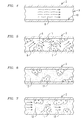
- the cooling passage 9 is formed by the hollow conductor 2 having an inner wall 10, as shown in FIG 4 .
- the fluid cooling medium 8 maybe cooling water, or cooling air, or hydrogen, etc.
- deposits or products of corrosion 11 accumulate on the inner wall of the hollow conductors 2, which are shown in FIG 5 .
- the accumulated deposits or products of corrosion 11 increase the dynamic flow losses of the fluid cooling medium 8 and impede heat conduction from the hollow conductors 2 to the fluid cooling medium 8.
- the decrease of heat removal through the fluid cooling medium 8 requires maintenance to the generator coil 1 to remove the deposits or products of corrosion 11 from the inner walls of the hollow conductors 2.
- the cooling passage of the hollow conductor 2 is filled with a shear hardening medium 12 during the maintenance, which is shown in FIG 6 .
- the shear hardening medium 12 has abrasive particles suspended therein.
- the shear hardening medium 12 may be, for example, a visco-elastic abrasive medium, or for example, a rheopectic poly filled with viscosity increasing stiffening agents and loadings of the abrasive particles, or for example, a semisolid polymer composition.
- the shear hardening medium 12 is applied with a hydraulic pressure.
- the hydraulic pressure locks the abrasive particles suspended in the shear hardening medium 12 into a matrix position.
- a matrix position is a semi-regular arrangement of the particles in the shear hardening medium that provides the abrasive action at the interface to the cooling passage.
- the viscosity of the shear hardening medium is partly a function of the hydraulic pressure.
- the applied hydraulic pressure locks the abrasive particles into the matrix position and does not exceed a capability of the hollow conductors to hold the pressure.
- the applied hydraulic pressure for example, may be in a range of 100 psi to 1,000 psi, or in a range of 200 psi to 800 psi, or in a range of 300 psi to 600 psi.
- a flow is imparted to the shear hardening medium 10 within the cooling passage in the hollow conductor 2.
- a shearing hardening force 13 is applied to the shear hardening medium 12 by the imparted flow, as shown in FIG 7 .
- FIG 8 shows an embodiment of a single pass cleaning.
- a unidirectional flow 14 is applied to the shear hardening medium 12 so that shear hardening medium 12 moves inside the hollow conductor 2 in one direction while under pressure.
- the flow of the pressurized shear hardening medium 12 and the locked abrasive particles 15 abrade the deposits or products of corrosion 11 into broken off deposits or products of corrosion 16.
- FIG 9 shows an embodiment of a reciprocated pass cleaning.
- alternate flows 17 are applied to the shear hardening medium 10 so that the shear hardening medium 12 moves inside the hollow conductor 2 in alternate flow directions while under pressure.
- the alternate flow of the pressurized shear hardening medium 10 and the locked abrasive particles 13 abrades the deposits or products of corrosion 11 into broken off deposits or products of corrosion 16.
- the shear hardening medium 12 moves inside the hollow conductor 2 for a sufficient period of time so that the deposits are abraded from the inner walls of the hollow conductor 2.
- the shear hardening medium 12 is released from the hydraulic pressure and drained from the hollow conductors 2.
- FIG 10 shows the residue of the shear hardening medium 12 is flushed out of the hollow conductor 2 by a flushing medium 18.
- the generator coil 1 After flushing out the shear hardening medium 12 from the hollow conductor 2, the generator coil 1 is returned to service with unimpeded flow of the cooling medium item 8 to provide adequate heat removal.
Landscapes
- Engineering & Computer Science (AREA)
- Power Engineering (AREA)
- Mechanical Engineering (AREA)
- Manufacturing & Machinery (AREA)
- Cleaning In General (AREA)
- Finish Polishing, Edge Sharpening, And Grinding By Specific Grinding Devices (AREA)
- Coils Of Transformers For General Uses (AREA)
- Transformer Cooling (AREA)
Applications Claiming Priority (1)
| Application Number | Priority Date | Filing Date | Title |
|---|---|---|---|
| US14/107,138 US20150165495A1 (en) | 2013-12-16 | 2013-12-16 | Abrasive cleaning of inner cooled generator coils |
Publications (2)
| Publication Number | Publication Date |
|---|---|
| EP2884635A2 true EP2884635A2 (fr) | 2015-06-17 |
| EP2884635A3 EP2884635A3 (fr) | 2015-12-16 |
Family
ID=52101099
Family Applications (1)
| Application Number | Title | Priority Date | Filing Date |
|---|---|---|---|
| EP14197231.5A Withdrawn EP2884635A3 (fr) | 2013-12-16 | 2014-12-10 | Nettoyage abrasif de bobines de générateur refroidies en interne |
Country Status (6)
| Country | Link |
|---|---|
| US (1) | US20150165495A1 (fr) |
| EP (1) | EP2884635A3 (fr) |
| JP (1) | JP2015120153A (fr) |
| KR (1) | KR20150070037A (fr) |
| CN (1) | CN104707824A (fr) |
| CA (1) | CA2874602A1 (fr) |
Families Citing this family (8)
| Publication number | Priority date | Publication date | Assignee | Title |
|---|---|---|---|---|
| US10826345B2 (en) * | 2017-05-26 | 2020-11-03 | Ge Aviation Systems Llc | Conductor and method of forming thereof |
| WO2019003397A1 (fr) * | 2017-06-28 | 2019-01-03 | 三菱製鋼株式会社 | Procédé de fabrication de stabilisateur creux |
| US11108307B2 (en) * | 2017-09-29 | 2021-08-31 | Honda Motor Co., Ltd. | Coil for rotary electric machine and insertion method |
| US12145182B2 (en) | 2020-06-12 | 2024-11-19 | The Boeing Company | Cleaning systems and methods of use thereof |
| EP4275901A1 (fr) * | 2022-05-12 | 2023-11-15 | Siemens Aktiengesellschaft | Bobine à refroidissement d'enroulement |
| CN114734365B (zh) * | 2022-06-13 | 2022-09-09 | 中国航发上海商用航空发动机制造有限责任公司 | 微细内流道的表面光整方法、微细内流道工件及光整介质 |
| CN115193833B (zh) * | 2022-07-15 | 2023-11-17 | 上海电力建设启动调整试验所有限公司 | 液体工质系统的冲洗装置与冲洗方法 |
| CN118157367B (zh) * | 2024-05-06 | 2024-07-16 | 比亚迪股份有限公司 | 绕组组件、电机、悬架系统及车辆 |
Family Cites Families (6)
| Publication number | Priority date | Publication date | Assignee | Title |
|---|---|---|---|---|
| CA1250146A (fr) * | 1982-09-08 | 1989-02-21 | Lawrence J. Rhoades | Dispositifs et methodes d'abrasion des surfaces de pieces |
| EP0634229B1 (fr) * | 1993-07-12 | 1998-10-07 | Promotec AG | Procédé, assemblage et dispositif pour le nettoyage et revêtement interne d'une tuyauterie |
| US6554006B2 (en) * | 2000-12-22 | 2003-04-29 | General Electric Company | Piping deposit removal from stator water cooling systems |
| US7276134B2 (en) * | 2004-10-18 | 2007-10-02 | General Electric Company | Methods and systems for sealing liquid cooled stator bar end connections for a generator |
| CA2731460C (fr) * | 2008-08-18 | 2013-10-22 | Cec-Systems Sa | Procede de traitement ainsi que sous-distributeur et dispositif de traitement pour le traitement de l'interieur d'un reseau de conduites |
| GB0823292D0 (en) * | 2008-12-20 | 2009-01-28 | Pipeline Cleaning Solutions Ltd | Treating moving and removing particles in fluid-carrying apparatus |
-
2013
- 2013-12-16 US US14/107,138 patent/US20150165495A1/en not_active Abandoned
-
2014
- 2014-12-10 EP EP14197231.5A patent/EP2884635A3/fr not_active Withdrawn
- 2014-12-12 CA CA2874602A patent/CA2874602A1/fr not_active Abandoned
- 2014-12-16 CN CN201410774443.6A patent/CN104707824A/zh active Pending
- 2014-12-16 JP JP2014253951A patent/JP2015120153A/ja active Pending
- 2014-12-16 KR KR1020140181711A patent/KR20150070037A/ko not_active Withdrawn
Non-Patent Citations (1)
| Title |
|---|
| None |
Also Published As
| Publication number | Publication date |
|---|---|
| EP2884635A3 (fr) | 2015-12-16 |
| KR20150070037A (ko) | 2015-06-24 |
| US20150165495A1 (en) | 2015-06-18 |
| CA2874602A1 (fr) | 2015-06-16 |
| JP2015120153A (ja) | 2015-07-02 |
| CN104707824A (zh) | 2015-06-17 |
Similar Documents
| Publication | Publication Date | Title |
|---|---|---|
| US20150165495A1 (en) | Abrasive cleaning of inner cooled generator coils | |
| CN100551556C (zh) | 管线外壁清洗机 | |
| CN106623275A (zh) | 一种超临界二氧化碳脉冲射流油管清污装置及方法 | |
| CN110024225B (zh) | 用于提供电力传输接口的方法、接口成形装置及用于成形电力传输接口的冷喷涂设备的用途 | |
| CN104674263A (zh) | 一种金属表面清洗方法 | |
| CN105861798B (zh) | 腐蚀孔的扩孔复合强化方法 | |
| CN103817605A (zh) | 水射流去毛刺表面精整装备 | |
| CN103817584B (zh) | 钢管外表面除鳞装置 | |
| CN110496828B (zh) | 利用冷热形变差自破壳除垢方法、装置及打壳锤头 | |
| CN108637586B (zh) | 一种导卫表面修复方法 | |
| CN204470705U (zh) | 具有高压除屑机制的锯切装置 | |
| CN204564687U (zh) | 旋转式的钻杆洗涤设备 | |
| CN104785477A (zh) | 一种油管管内垢物打磨工具 | |
| KR100834035B1 (ko) | 드라이아이스를 이용한 관로 갱생방법 및 장치 | |
| RU2137908C1 (ru) | Способ разрушения гидратно-ледяных, асфальтеносмолистых и парафиновых отложений в стволе скважины, оборудованной штанговым глубинным насосом | |
| JP2008087103A (ja) | スケール除去装置及びスケール除去方法 | |
| RU157614U1 (ru) | Устройство для механической очистки внутренней поверхности насосно-компрессорных труб от отложений | |
| CN103817585B (zh) | 钢管外表面除鳞主机 | |
| SA521421800B1 (ar) | التنبؤ بفعالية التنظيف الميكانيكي أسفل البئر في جدران حفرة البئر أثناء عمليات إزاحة موائع حفرة البئر | |
| CN103062573A (zh) | 防腐除垢输油管道 | |
| US20130287616A1 (en) | Progressing cavity pump/motor | |
| CN205100940U (zh) | 一种采油刮蜡清洁装置 | |
| JP5416461B2 (ja) | 鋼構造体のさび除去方法 | |
| CN106457326B (zh) | 用于干式拉拔绞盘的冷却系统 | |
| WO2010091812A2 (fr) | Dispositif de traitement de surface |
Legal Events
| Date | Code | Title | Description |
|---|---|---|---|
| PUAI | Public reference made under article 153(3) epc to a published international application that has entered the european phase |
Free format text: ORIGINAL CODE: 0009012 |
|
| 17P | Request for examination filed |
Effective date: 20141210 |
|
| AK | Designated contracting states |
Kind code of ref document: A2 Designated state(s): AL AT BE BG CH CY CZ DE DK EE ES FI FR GB GR HR HU IE IS IT LI LT LU LV MC MK MT NL NO PL PT RO RS SE SI SK SM TR |
|
| AX | Request for extension of the european patent |
Extension state: BA ME |
|
| PUAL | Search report despatched |
Free format text: ORIGINAL CODE: 0009013 |
|
| AK | Designated contracting states |
Kind code of ref document: A3 Designated state(s): AL AT BE BG CH CY CZ DE DK EE ES FI FR GB GR HR HU IE IS IT LI LT LU LV MC MK MT NL NO PL PT RO RS SE SI SK SM TR |
|
| AX | Request for extension of the european patent |
Extension state: BA ME |
|
| RIC1 | Information provided on ipc code assigned before grant |
Ipc: H02K 3/22 20060101ALI20151110BHEP Ipc: B08B 9/027 20060101ALN20151110BHEP Ipc: H02K 15/00 20060101AFI20151110BHEP |
|
| STAA | Information on the status of an ep patent application or granted ep patent |
Free format text: STATUS: THE APPLICATION IS DEEMED TO BE WITHDRAWN |
|
| 18D | Application deemed to be withdrawn |
Effective date: 20160617 |