EP2884591A1 - Elektrischer Kabelschuh für Verbindungsklemme, entsprechendes elektrisches System und Verbindungsverfahren eines solchen Kabelschuhs an eine Verbindungsklemme - Google Patents
Elektrischer Kabelschuh für Verbindungsklemme, entsprechendes elektrisches System und Verbindungsverfahren eines solchen Kabelschuhs an eine Verbindungsklemme Download PDFInfo
- Publication number
- EP2884591A1 EP2884591A1 EP14197686.0A EP14197686A EP2884591A1 EP 2884591 A1 EP2884591 A1 EP 2884591A1 EP 14197686 A EP14197686 A EP 14197686A EP 2884591 A1 EP2884591 A1 EP 2884591A1
- Authority
- EP
- European Patent Office
- Prior art keywords
- connection
- terminal
- lug
- configuration
- base
- Prior art date
- Legal status (The legal status is an assumption and is not a legal conclusion. Google has not performed a legal analysis and makes no representation as to the accuracy of the status listed.)
- Granted
Links
Images


Classifications
-
- H—ELECTRICITY
- H01—ELECTRIC ELEMENTS
- H01R—ELECTRICALLY-CONDUCTIVE CONNECTIONS; STRUCTURAL ASSOCIATIONS OF A PLURALITY OF MUTUALLY-INSULATED ELECTRICAL CONNECTING ELEMENTS; COUPLING DEVICES; CURRENT COLLECTORS
- H01R13/00—Details of coupling devices of the kinds covered by groups H01R12/70 or H01R24/00 - H01R33/00
- H01R13/02—Contact members
- H01R13/10—Sockets for co-operation with pins or blades
- H01R13/11—Resilient sockets
- H01R13/112—Resilient sockets forked sockets having two legs
-
- H—ELECTRICITY
- H01—ELECTRIC ELEMENTS
- H01R—ELECTRICALLY-CONDUCTIVE CONNECTIONS; STRUCTURAL ASSOCIATIONS OF A PLURALITY OF MUTUALLY-INSULATED ELECTRICAL CONNECTING ELEMENTS; COUPLING DEVICES; CURRENT COLLECTORS
- H01R13/00—Details of coupling devices of the kinds covered by groups H01R12/70 or H01R24/00 - H01R33/00
- H01R13/40—Securing contact members in or to a base or case; Insulating of contact members
- H01R13/405—Securing in non-demountable manner, e.g. moulding, riveting
- H01R13/41—Securing in non-demountable manner, e.g. moulding, riveting by frictional grip in grommet, panel or base
-
- H—ELECTRICITY
- H01—ELECTRIC ELEMENTS
- H01R—ELECTRICALLY-CONDUCTIVE CONNECTIONS; STRUCTURAL ASSOCIATIONS OF A PLURALITY OF MUTUALLY-INSULATED ELECTRICAL CONNECTING ELEMENTS; COUPLING DEVICES; CURRENT COLLECTORS
- H01R4/00—Electrically-conductive connections between two or more conductive members in direct contact, i.e. touching one another; Means for effecting or maintaining such contact; Electrically-conductive connections having two or more spaced connecting locations for conductors and using contact members penetrating insulation
- H01R4/28—Clamped connections, spring connections
- H01R4/30—Clamped connections, spring connections utilising a screw or nut clamping member
- H01R4/34—Conductive members located under head of screw
-
- H—ELECTRICITY
- H01—ELECTRIC ELEMENTS
- H01R—ELECTRICALLY-CONDUCTIVE CONNECTIONS; STRUCTURAL ASSOCIATIONS OF A PLURALITY OF MUTUALLY-INSULATED ELECTRICAL CONNECTING ELEMENTS; COUPLING DEVICES; CURRENT COLLECTORS
- H01R4/00—Electrically-conductive connections between two or more conductive members in direct contact, i.e. touching one another; Means for effecting or maintaining such contact; Electrically-conductive connections having two or more spaced connecting locations for conductors and using contact members penetrating insulation
- H01R4/28—Clamped connections, spring connections
- H01R4/38—Clamped connections, spring connections utilising a clamping member acted on by screw or nut
- H01R4/44—Clamping areas on both sides of screw
-
- H—ELECTRICITY
- H01—ELECTRIC ELEMENTS
- H01R—ELECTRICALLY-CONDUCTIVE CONNECTIONS; STRUCTURAL ASSOCIATIONS OF A PLURALITY OF MUTUALLY-INSULATED ELECTRICAL CONNECTING ELEMENTS; COUPLING DEVICES; CURRENT COLLECTORS
- H01R11/00—Individual connecting elements providing two or more spaced connecting locations for conductive members which are, or may be, thereby interconnected, e.g. end pieces for wires or cables supported by the wire or cable and having means for facilitating electrical connection to some other wire, terminal, or conductive member, blocks of binding posts
- H01R11/11—End pieces or tapping pieces for wires, supported by the wire and for facilitating electrical connection to some other wire, terminal or conductive member
- H01R11/12—End pieces terminating in an eye, hook, or fork
Definitions
- the present invention relates to a lug for electrical connection to an electrical connection terminal, an electrical system comprising an electrical switching device and an auxiliary device connected to one another via an electric cable or cables provided with such a terminal lug. connection, and a method of connecting such a connection terminal to a connection terminal.
- a persistent challenge in the field of connections and more specifically the connection of a connection terminal to a connection terminal is to ensure optimum electrical contact between the terminal and the terminal connection, to ensure electrical contact quality.
- connection terminal for example as described in WO 2007/143805 A2
- a connecting lug comprising a terminal receiving means for connecting the lug to a connection terminal.
- the orifice is extended by a slot allowing insertion into the orifice of a screw belonging to the connection means.
- the connection means comprise the screw and a stirrup, whereas during the connection of the terminal to the connection terminal, the terminal is positioned in contact with the connection terminal, so that the screw goes through the slit and is found in the hole.
- connection terminal is intended to be connected, on the one hand, to an electrical cable comprising the terminal and, on the other hand, to an electrical power conductor, it is difficult to position the electrical power cable. in the connection terminal and to guarantee a high quality electrical contact of the terminal and the electrical power conductor with the connection range.
- the object of the invention is therefore to provide an electrical connection lug to a connection terminal allowing improved contact quality of the lug with the connection terminal, especially when an electric cable provided with the lug and a driver Power supply are connected to the connection terminal.
- the subject of the invention is an electrical connection terminal to an electrical connection terminal, the terminal comprising a connection zone to an electrical wire and a base, the base comprising a passage opening of a connection means. and two lateral sides extending generally along a longitudinal axis of the terminal.
- the base comprises on at least one of its lateral sides at least one element projecting from the corresponding lateral side and the rest of the base.
- the projecting elements are adapted to be inserted in the connection terminal and more precisely in the walls of the connection terminal, which makes it possible to connect the terminal to the connection terminal immovably and thus to guarantee an improved electrical contact quality.
- the irremovable holding of the terminal to the connection terminal makes it possible to avoid any unwanted disconnection, unwanted, of the terminal and therefore of an electrical conductor provided with the terminal, with respect to the connection terminal.
- the fact that the lug is connected irremovably also facilitates the connection of an electrical power conductor to the connection terminal, in addition to the connection of an electric cable with the lug.
- the invention also relates to an electrical system comprising at least one electrical connection terminal and at least one such electrical connection terminal to the one or one of the electrical connection terminals, each connection terminal comprising a connection means and a receiving housing of the corresponding lug, the housing comprising a connection pad and two side walls between which the connection pad extends.
- the projecting element or elements are adapted to be inserted in one of the side walls, during the connection of each lug to the corresponding connection terminal.
- the invention also relates to a method of connecting an electrical connection terminal to an electrical connection terminal, the terminal comprising a connection zone to an electrical wire and a base, the base comprising a passage opening of a connecting means and two lateral sides extending generally along a longitudinal axis of the terminal, the connection terminal comprising the connecting means and a receiving housing of the terminal, the housing comprising a connection pad and two side walls between which extends the connection range.
- the method comprises a step of connecting the terminal to the connection terminal, during which at least one element, projecting from a lateral side of the base, is inserted in one of the side walls.
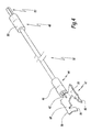
- the electrical system 10 shown on the figure 1 comprises an electrical switching device 12, such as a contactor, and an auxiliary device 14 electrically coupled to the switching device 12.
- an electrical switching device 12 such as a contactor
- auxiliary device 14 electrically coupled to the switching device 12.
- the switching device 12 is a three-phase contactor 12 and comprises a housing 16, three first input terminals 20 of a current, also called “first input terminals”, and three first connection terminals 22 of the output. current, also called “first output terminals”.
- the contactor 12 is known per se and comprises a control device, not shown, capable of interrupting the flow of current between the first input and output terminals 22, that is to say between electrical conductors 24 of power, of which only one is represented at figure 1 connected respectively to the first input terminals 20 and the second output terminals 22.
- the auxiliary apparatus 14 comprises four second input connection terminals 26 and four second output connection terminals 28.
- the auxiliary apparatus 14 is able to monitor the operation of the switching device 12.
- the auxiliary apparatus 14 is for example, able to measure the current flowing through the first input and output terminals 22 or to measure the temperature of the first input and output terminals 22.
- the auxiliary device 14 comprises a computing device , not shown, adapted to measure the electrical power and the electrical energy at each first input terminal 20 and output terminal 22.
- the auxiliary device 14 is generally able to communicate, via a wireless link or in wired variant, with a data concentrator, not shown.
- each of its first input terminal 20 which is connected, via a respective electric cable 32, to one of the corresponding second input terminals 26 and, on the other hand, each of its first output terminal 22 which is connected, via a respective electric cable 32, to one of the corresponding second output terminals 28.
- Each first input terminal 20 and output terminal 22 comprises means 34, visible at the figure 2 connecting electrical cables 32 and electrical power conductors 24 to itself.
- the first input and output terminals 22 each comprise a housing 36 for receiving an electrical cable 32 and an electrical conductor 24.
- Each electrical power conductor 24 is connected either to one of the first input terminals 20 or to one of the first output terminals 22. More precisely, each electrical power conductor 24 connected to one of the first terminals input 20 is electrically connected, via switch 12, to the power conductor 24 connected to the corresponding first output terminal 22. Each electrical conductor 24 comprises an end portion 38 adapted to be inserted into the corresponding first connecting terminal 20, 22.
- Each electrical cable 32 comprises a resistive wire 42, a first connection end 44 provided with a heat-shrinkable sleeve 46 and a first connection member 47 to one of the first connection terminals 20, 22, as well as a second connection end 48 also provided with a heat-shrinkable sleeve 50 and a second member 52 for connection to one of the second connection terminals 26, 28.
- each electrical cable 32 extends between one of the first terminals 20, or output connection 22 and respectively one of the second input terminals 26, or output 28, corresponding.
- connection means 34 is adapted to maintain the connection between the corresponding power conductor 24 and the corresponding first connection terminal 20, 22.
- Each connection means 34 comprises a screw 54 associated with a stirrup 56.
- the housing 36 is adapted to receive the first connecting member 47 and the end portion 38 and comprises two side walls 58, 59 between which a connection pad 60 extends.
- the side walls 58, 59 are perpendicular to the connection pad 60.
- the first connecting member 47 corresponds to a terminal 47 which comprises a zone 64 for connecting the resistive wire 42 and a base 66.
- the lug 47 is obtained, for example, by folding and cutting a metal plate.
- the lug 47 extends along a longitudinal axis X47.
- the screw 54 and the stirrup 56 are able to exert a pressure force on the terminal 47 and the end portion 38, in order to maintain electrical contact between the connection pad 60, the terminal portion 38 and the pod 47.
- the screw 54 is adapted to be screwed or unscrewed in order to maintain the corresponding electrical power conductor 24 electrically connected to the corresponding connection pad 60 or respectively in order to disconnect the corresponding electrical power conductor 24 relative to the corresponding connection pad 60. .
- the stirrup 56 and the connection pad 60 are spaced from one another and form a receiving space E of the terminal 47 and the electrical power conductor 24.
- connection pad 60 includes a hole 65 for receiving the screw 54.
- the connecting zone 64 is shaped to maintain an electrical connection between the base 66 and the resistive wire 42.
- the terminal 47 and more precisely its base 66 is plastically deformable between two configurations, more precisely since an initial configuration presented to the Figures 2 to 6 to a connection configuration at the corresponding first connection terminal 20, 22, shown in FIGS. figures 7 and 8 .
- the base 66 includes a first portion 68 and a second portion 70.
- the base 66 also includes a hole 72 for the passage of the screw 54 defined between the first 68 and second 70 parts.
- the first 68 and second 70 parts respectively comprise a first lateral side 74 and a second lateral side 76, which belong to a first plane P of the lug 47 and define this first plane P.
- the first and second lateral sides 74, 76 are extend globally along the longitudinal axis X47.
- the distance between the two lateral sides 74, 76, when the lug is in initial configuration, has a first value D74i which is lower than its value D74c when the lug is in connection configuration.
- the first lateral side 74 is opposite one of the two side walls, while the second lateral side 76 is opposite the other 58 side wall.
- the first 68 and second 70 parts also each comprise a first 78 and a second 80 fins which delimit between them, opposite the orifice 72, a slot 82.
- a first angle ⁇ 1 measured between the first 68 and second 70 parts, on the side of the first plane P, is between 90 ° and 170 °, preferably between 120 ° and 150 °.
- the corresponding base 66 When the lug 47 is in its initial configuration and is inserted into one of the first connection terminals 20, 22, the corresponding base 66 has, as shown in FIG. figure 3 its edge 84 facing the connection pad 60 and its lateral sides 74, 76 In other words, the base 66 has its edge 84 which is closer to the connection pad 60 than its lateral sides 74, 76.
- the first angle ⁇ 1 is equal to 180 ° with a margin of error of plus or minus 5 °.
- the first 68 and second 70 parts are positioned against the connection pad 60 and extend parallel or almost parallel to less than 5 °, to the connection pad 60 and the foreground P.
- the orifice 72 is a through-hole aligned with the hole of the connection pad 60 when the lug 47 is connected to the connection pad 60.
- the first 74 and second 76 lateral sides each comprise two elements 86 projecting from the rest of the base 66 and the lateral side 74, 76 corresponding.
- the projecting elements 86 are respectively oriented towards the side walls 59, 58, when the lug 47 is connected to the connection pad 60.
- the first 78 and second fins 80 are inclined relative to the first plane P and the slot 82 corresponds to an access port slot for the connection means 34, specifically for the screw 54.
- the minimum width of the slot 82 measured parallel to the first plane P and perpendicular to one of the lateral sides 74, 76 has, in the initial configuration, a value W82i greater than the diameter D54 of the screw.
- a second angle ⁇ 2 between each fin 78, 80 and the first plane P, measured on the plane P side is between 20 ° and 70 °, preferably between 40 ° and 60 °.
- the first 78 and second 80 fins are adapted to be flattened by the stirrup 56 during the plastic deformation of the terminal during its transition from the initial configuration to the connection configuration.
- the minimum width of the slot 82 measured parallel to the first plane P and perpendicular to one of the lateral sides 74, 76, has a value W82c less than the diameter of the screw D54.
- the second angle ⁇ 2 is between 0 ° and 10 °.
- the width of the base 66, measured in initial configuration, at each projecting element 86, parallel to the plane P and perpendicular to the lateral side 74, 76 corresponding, has a value W66i less than or equal to the distance D58 measured between the two. side walls 58, 59, when the lug 47 is connected to the first connection terminal 20, 22, at the corresponding projecting element 86 and perpendicular to the corresponding side wall 58, 59.
- the width of the base 66 measured in connection configuration of the lug 47, at each projecting element 86, parallel to the plane P and perpendicular to the lateral side 74, 76 corresponding, has a value W66c greater than the distance D58 between the two side walls 58, 59.
- the projecting elements 86 are adapted to be inserted in the side walls 58, 59, in the connection configuration of the terminal 47, since the value W66c is greater than the distance D58.
- the projecting elements 86 define claws adapted to be inserted into the corresponding side wall 58, 59 when the lug 47 is deformed in connection configuration.
- the projecting elements 86 are positioned at four corners formed by the base 66.
- each projecting element 86 measured perpendicularly to the lateral side 74, 76 corresponding to, for example, a W86 value less than 3 mm, preferably between 0.4 mm and 1.2 mm.
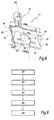
- FIG 8 a flowchart of a method of connecting the electrical cable 32 and one of the power electrical conductors 24 to one of the first connection terminals 20, 22 is shown.
- a first step 100 the lug 47 is positioned on the corresponding first connection terminal 20, 22 in order to be connected thereto. More specifically, the fins 78, 82 are brought into contact with the connection pad 60 and the projecting elements 86 are oriented towards the bracket 56.
- the pod 47 is inserted at the first corresponding connection terminal 20, 22, so that the screw 54 is positioned in the orifice 72. More specifically, the screw 54 is already installed and disposed in the hole 65 and the lug 47 is inserted into the connection terminal 20, 22 corresponding, so that the 54 screws through the slot 82 and are found in the orifice 72.
- the terminal 47 and more precisely its base 66, is flattened.
- the connection means 34 exerts a pressure force on the base 66 to plastically deform the lug from its initial configuration to its connection configuration.
- a screwing operation of the screw 54 is performed, so that the stirrup 56 moves towards the connection pad 60 and flatten the base 66, that is to say the first 68 and second 70 parts.
- the projecting elements 86 are inserted into or scratch the corresponding side walls 58, 59 and the lug 47 is thus fixed irremovably to the corresponding first connection terminal 20, 22.
- the lug 47 is generally parallel to the connection pad 60 and flattened at the bottom of the first connection terminal 20, 22, that is to say against the connection pad 60.
- the fins 78, 80 are also flattened so as to reduce the width minimum of the slot 82 and to prevent tearing of the lug 47 relative to the corresponding first connection terminal 20, 22.
- the electric cable 32 intended to be connected to the corresponding first connection terminal 20, 22 via its lug 47, is also connected at its second end 48, via the second element connection 52 to the corresponding second connection terminal 26, 28.
- the screw 54 is unscrewed and the stirrup 56 moves in a direction opposite to the connection pad 60.
- the space E is adapted to receive the corresponding 24-wire power conductor. More precisely, the receiving space E is formed between, on the one hand, the connection pad 60 and the pad 47 and, on the other hand, the bracket 56.
- steps 100, 102 and 104 are performed for each first connection terminal 20, 22 and following step 104 an operator has the electrical system 10, which he will install in an electrical installation between the electrical power conductors 24.
- the electrical power conductor 24 and more precisely, the end portion 38 is inserted into the receiving space E, in order to be connected to the corresponding first connection terminal 20, 22.
- a screwing operation of the screw 54 is carried out in order to move the stirrup 56 towards the connection pad 60 and the lug 47 and to keep the end portion 38 connected to the connection pad 60 and wedged between the stirrup 56 and the lug 47.
- the inclination of the first 78 and second 80 fins makes it possible to form the slit 82 which is clean, in the initial configuration of the lug 47, to let the screw 54 pass so that it is positioned in the orifice 72. Indeed, the screw 54 is in place in each first connection terminal 20, 22, prior to the connection of the lug 47 on the corresponding connection pad 60. Moreover, the fact that the first 78 and second 80 fins are inclined allows, during the deformation of the lug 47 in the connection configuration, to reduce the width of the slot 82 to trap the screw 54 in the orifice 72 and prevent disconnection of the lug 47 of the corresponding first connection terminal 20, 22.
- the flattening of the lug 47 is guaranteed, which, following the operation, unscrewing 104, to leave the space E between the connection pad 60 and the stirrup 56.
- the volume of the space E is optimized, which makes it easier to access the corresponding first connection terminal 20, 22 after the connection of the terminal 47.
- the space E facilitates the connection of the electrical power conductor 24, that is to say from its end portion 38, to the corresponding first connection terminal 20, 22. Since the connection of the electrical conductor 24 is facilitated and that the lug is flat against the corresponding connection pad 60, the quality of the electrical contact between the connection pad 60, the lug 47 and the electrical power conductor 24 is guaranteed and improved.
- first 78 and second 80 fins, as well as the projecting elements 86, ensure that the lug 47 has a non-removable character with respect to the corresponding first connection terminal 20, 22, in order to guarantee the connection between the auxiliary device 14 and the contactor 12.
- the resistive son 42 are non-removable and thus the connection between the switching device 12 and the auxiliary device 14 is guaranteed to be removable by the operator.
- the electrical system 10 presented to the figure 1 allows the control of three-phase capacitor banks, which promote the compensation of the reactive energy caused by highly inductive loads in an electrical installation. More precisely, thanks to the capacitor banks, the current drawn on an electrical network supplying the electrical installation is reduced.
- the resistive son 42 can absorb current peaks passing through the first terminals 20,22.
- the lug 47 allows the connection of the electric cable 32 or another type of electrical cable to any type of connection terminal comprising a connection pad and side walls, similar to the connection pad 60 and the side walls 58, 59.
- the switching device 12 is a single-phase contactor comprising only one or two first input terminals and one or two first output terminals.
- the switching device 12 is, for example, a circuit breaker.
- only one of the first 68 and second 70 parts comprises a fin forming with the rest of the terminal slot 82.
- each lateral side 74, 76 comprises a single projecting element 86.
- only one of the lateral sides 74, 76 comprises one or more projecting elements 86.
- projecting elements are arranged along the entire length of the lateral sides 74, 76 and the width of the protruding elements, measured perpendicularly to the side walls 58, 59, varies in increasing or decreasing manner along the lateral sides 74 , 76.
- the base 66 when the lug 47 is inserted in one of the first connection terminals 20, 22, previously at its connection to one of the first connection terminals 20, 22, the base 66 corresponding to its edge 84 oriented to the stirrup 56 and its lateral sides 74, 76 in contact with the connection pad 60.
- connection means 34 may be of any type as long as it is capable of applying a pressure force on the lug 47, that is to say on the base 66, in order to deform the lug 47 from its initial configuration to its connection configuration.
Landscapes
- Details Of Connecting Devices For Male And Female Coupling (AREA)
- Connections Arranged To Contact A Plurality Of Conductors (AREA)
Applications Claiming Priority (1)
| Application Number | Priority Date | Filing Date | Title |
|---|---|---|---|
| FR1362631A FR3015132B1 (fr) | 2013-12-13 | 2013-12-13 | Cosse de raccordement electrique a une borne de connexion, systeme electrique associe et procede de connexion d'une telle cosse a une borne de connexion |
Publications (2)
| Publication Number | Publication Date |
|---|---|
| EP2884591A1 true EP2884591A1 (de) | 2015-06-17 |
| EP2884591B1 EP2884591B1 (de) | 2020-09-23 |
Family
ID=50489229
Family Applications (1)
| Application Number | Title | Priority Date | Filing Date |
|---|---|---|---|
| EP14197686.0A Active EP2884591B1 (de) | 2013-12-13 | 2014-12-12 | Elektrischer kabelschuh für verbindungsklemme, entsprechendes elektrisches system und verbindungsverfahren eines solchen kabelschuhs an eine verbindungsklemme |
Country Status (3)
| Country | Link |
|---|---|
| EP (1) | EP2884591B1 (de) |
| CN (1) | CN204793320U (de) |
| FR (1) | FR3015132B1 (de) |
Citations (2)
| Publication number | Priority date | Publication date | Assignee | Title |
|---|---|---|---|---|
| US3344394A (en) * | 1966-05-16 | 1967-09-26 | Zinsco Electrical Products | Limited engagement lug assembly |
| WO2007143805A2 (en) | 2006-06-14 | 2007-12-21 | Tyco Electronics Brasil Ltda | Closed idc terminal |
Family Cites Families (2)
| Publication number | Priority date | Publication date | Assignee | Title |
|---|---|---|---|---|
| US6242993B1 (en) * | 1995-03-13 | 2001-06-05 | Square D Company | Apparatus for use in arcing fault detection systems |
| DE102006049810B4 (de) * | 2006-10-17 | 2008-07-10 | Siemens Ag | Leistungsschalter, insbesondere Kompaktleistungsschalter, und Hilfsleiteranschluss für einen Leistungsschalter |
-
2013
- 2013-12-13 FR FR1362631A patent/FR3015132B1/fr not_active Expired - Fee Related
-
2014
- 2014-12-12 EP EP14197686.0A patent/EP2884591B1/de active Active
- 2014-12-15 CN CN201420794850.9U patent/CN204793320U/zh not_active Expired - Lifetime
Patent Citations (2)
| Publication number | Priority date | Publication date | Assignee | Title |
|---|---|---|---|---|
| US3344394A (en) * | 1966-05-16 | 1967-09-26 | Zinsco Electrical Products | Limited engagement lug assembly |
| WO2007143805A2 (en) | 2006-06-14 | 2007-12-21 | Tyco Electronics Brasil Ltda | Closed idc terminal |
Also Published As
| Publication number | Publication date |
|---|---|
| FR3015132B1 (fr) | 2017-03-10 |
| EP2884591B1 (de) | 2020-09-23 |
| CN204793320U (zh) | 2015-11-18 |
| FR3015132A1 (fr) | 2015-06-19 |
Similar Documents
| Publication | Publication Date | Title |
|---|---|---|
| EP2521224B1 (de) | Schnellverbindungsvorrichtung für ein elektrisches Gerät | |
| FR3082669A1 (fr) | Clip metallique de connexion electrique d’un fil conducteur a un element metallique | |
| EP3314682B1 (de) | Elektrische energiespeichermodul | |
| FR2742918A1 (fr) | Dispositif de raccordement d'un conducteur exterieur tel un cable a une plage de contact d'un appareil electrique | |
| EP2884591B1 (de) | Elektrischer kabelschuh für verbindungsklemme, entsprechendes elektrisches system und verbindungsverfahren eines solchen kabelschuhs an eine verbindungsklemme | |
| FR3020467A1 (fr) | Dispositif de mesure d'au moins une grandeur electrique d'un courant destine a circuler dans un appareil electrique, et ensemble comprenant un tel dispositif | |
| WO2018011481A1 (fr) | Dispositif de mesure d un courant a serrage vertical sur une borne de batterie | |
| FR2766297A1 (fr) | Appareil electrique portant un support de contact fixe et une borne de raccordement | |
| FR2963488A1 (fr) | Embout multipolaire de connexion electrique | |
| FR2772979A1 (fr) | Dispositif de raccordement electrique d'un bloc differentiel sur un disjoncteur ou analogue et bloc differentiel equipe d'un tel dispositif | |
| EP2990811B1 (de) | Kontaktlose messvorrichtung für elektrische spannung in einem mittel- oder hochspannungs-stromnetzkabel | |
| FR3010838A1 (fr) | Borne a double systeme de raccordement electrique, en particulier pour un appareil de protection electrique basse tension, et appareil comportant une telle borne | |
| EP4343805A1 (de) | Schutzmodul für einen eingangsstrom eines elektrischen schaltgerätes vom nh-schmelzsicherungstyp | |
| EP2190275A1 (de) | Gehäuse für ein elektronisches Modul zur Steuerung einer Maschine | |
| EP1825278B1 (de) | Elektrische verbindungseinrichtung für einen polyphasen-stromzähler | |
| BE1030628B1 (fr) | Un dispositif de protection contre la coupure de courant pour véhicule électrique | |
| FR3127637A1 (fr) | Dispositif de protection pour accumulateur électrochimique prismatique | |
| EP3599629B1 (de) | Elektrische trennschaltervorrichtung für fahrzeug und entsprechendes fahrzeug | |
| FR3101193A1 (fr) | Appareil de coupure électrique à fusible | |
| EP3667688A1 (de) | Elektrische einheit, die ein kapazitives element umfasst | |
| EP3561968A1 (de) | Elektrisches anschlusssystem für spannungstransformator | |
| EP3435398B1 (de) | Elektrisches differentialschutzgerät | |
| FR3156255A1 (fr) | Appareillage de protection à coupure électronique | |
| EP4343799A1 (de) | Stromumwandlungsmodul für eine elektrische schaltanlage vom nh-schmelzsicherungstyp | |
| BE1010987A3 (fr) | Dispositif de protection automatique contre les surcourants, du type a detente, avec fonction de mise a la masse. |
Legal Events
| Date | Code | Title | Description |
|---|---|---|---|
| PUAI | Public reference made under article 153(3) epc to a published international application that has entered the european phase |
Free format text: ORIGINAL CODE: 0009012 |
|
| 17P | Request for examination filed |
Effective date: 20141212 |
|
| AK | Designated contracting states |
Kind code of ref document: A1 Designated state(s): AL AT BE BG CH CY CZ DE DK EE ES FI FR GB GR HR HU IE IS IT LI LT LU LV MC MK MT NL NO PL PT RO RS SE SI SK SM TR |
|
| AX | Request for extension of the european patent |
Extension state: BA ME |
|
| R17P | Request for examination filed (corrected) |
Effective date: 20150803 |
|
| RBV | Designated contracting states (corrected) |
Designated state(s): AL AT BE BG CH CY CZ DE DK EE ES FI FR GB GR HR HU IE IS IT LI LT LU LV MC MK MT NL NO PL PT RO RS SE SI SK SM TR |
|
| STAA | Information on the status of an ep patent application or granted ep patent |
Free format text: STATUS: EXAMINATION IS IN PROGRESS |
|
| 17Q | First examination report despatched |
Effective date: 20170904 |
|
| GRAP | Despatch of communication of intention to grant a patent |
Free format text: ORIGINAL CODE: EPIDOSNIGR1 |
|
| STAA | Information on the status of an ep patent application or granted ep patent |
Free format text: STATUS: GRANT OF PATENT IS INTENDED |
|
| INTG | Intention to grant announced |
Effective date: 20200528 |
|
| GRAS | Grant fee paid |
Free format text: ORIGINAL CODE: EPIDOSNIGR3 |
|
| GRAA | (expected) grant |
Free format text: ORIGINAL CODE: 0009210 |
|
| STAA | Information on the status of an ep patent application or granted ep patent |
Free format text: STATUS: THE PATENT HAS BEEN GRANTED |
|
| AK | Designated contracting states |
Kind code of ref document: B1 Designated state(s): AL AT BE BG CH CY CZ DE DK EE ES FI FR GB GR HR HU IE IS IT LI LT LU LV MC MK MT NL NO PL PT RO RS SE SI SK SM TR |
|
| REG | Reference to a national code |
Ref country code: GB Ref legal event code: FG4D Free format text: NOT ENGLISH |
|
| REG | Reference to a national code |
Ref country code: CH Ref legal event code: EP |
|
| REG | Reference to a national code |
Ref country code: DE Ref legal event code: R096 Ref document number: 602014070432 Country of ref document: DE |
|
| REG | Reference to a national code |
Ref country code: IE Ref legal event code: FG4D Free format text: LANGUAGE OF EP DOCUMENT: FRENCH |
|
| REG | Reference to a national code |
Ref country code: AT Ref legal event code: REF Ref document number: 1317326 Country of ref document: AT Kind code of ref document: T Effective date: 20201015 |
|
| PG25 | Lapsed in a contracting state [announced via postgrant information from national office to epo] |
Ref country code: GR Free format text: LAPSE BECAUSE OF FAILURE TO SUBMIT A TRANSLATION OF THE DESCRIPTION OR TO PAY THE FEE WITHIN THE PRESCRIBED TIME-LIMIT Effective date: 20201224 Ref country code: BG Free format text: LAPSE BECAUSE OF FAILURE TO SUBMIT A TRANSLATION OF THE DESCRIPTION OR TO PAY THE FEE WITHIN THE PRESCRIBED TIME-LIMIT Effective date: 20201223 Ref country code: NO Free format text: LAPSE BECAUSE OF FAILURE TO SUBMIT A TRANSLATION OF THE DESCRIPTION OR TO PAY THE FEE WITHIN THE PRESCRIBED TIME-LIMIT Effective date: 20201223 Ref country code: SE Free format text: LAPSE BECAUSE OF FAILURE TO SUBMIT A TRANSLATION OF THE DESCRIPTION OR TO PAY THE FEE WITHIN THE PRESCRIBED TIME-LIMIT Effective date: 20200923 Ref country code: HR Free format text: LAPSE BECAUSE OF FAILURE TO SUBMIT A TRANSLATION OF THE DESCRIPTION OR TO PAY THE FEE WITHIN THE PRESCRIBED TIME-LIMIT Effective date: 20200923 Ref country code: FI Free format text: LAPSE BECAUSE OF FAILURE TO SUBMIT A TRANSLATION OF THE DESCRIPTION OR TO PAY THE FEE WITHIN THE PRESCRIBED TIME-LIMIT Effective date: 20200923 |
|
| REG | Reference to a national code |
Ref country code: AT Ref legal event code: MK05 Ref document number: 1317326 Country of ref document: AT Kind code of ref document: T Effective date: 20200923 |
|
| PG25 | Lapsed in a contracting state [announced via postgrant information from national office to epo] |
Ref country code: LV Free format text: LAPSE BECAUSE OF FAILURE TO SUBMIT A TRANSLATION OF THE DESCRIPTION OR TO PAY THE FEE WITHIN THE PRESCRIBED TIME-LIMIT Effective date: 20200923 Ref country code: RS Free format text: LAPSE BECAUSE OF FAILURE TO SUBMIT A TRANSLATION OF THE DESCRIPTION OR TO PAY THE FEE WITHIN THE PRESCRIBED TIME-LIMIT Effective date: 20200923 |
|
| REG | Reference to a national code |
Ref country code: NL Ref legal event code: MP Effective date: 20200923 |
|
| REG | Reference to a national code |
Ref country code: LT Ref legal event code: MG4D |
|
| PG25 | Lapsed in a contracting state [announced via postgrant information from national office to epo] |
Ref country code: SM Free format text: LAPSE BECAUSE OF FAILURE TO SUBMIT A TRANSLATION OF THE DESCRIPTION OR TO PAY THE FEE WITHIN THE PRESCRIBED TIME-LIMIT Effective date: 20200923 Ref country code: RO Free format text: LAPSE BECAUSE OF FAILURE TO SUBMIT A TRANSLATION OF THE DESCRIPTION OR TO PAY THE FEE WITHIN THE PRESCRIBED TIME-LIMIT Effective date: 20200923 Ref country code: LT Free format text: LAPSE BECAUSE OF FAILURE TO SUBMIT A TRANSLATION OF THE DESCRIPTION OR TO PAY THE FEE WITHIN THE PRESCRIBED TIME-LIMIT Effective date: 20200923 Ref country code: NL Free format text: LAPSE BECAUSE OF FAILURE TO SUBMIT A TRANSLATION OF THE DESCRIPTION OR TO PAY THE FEE WITHIN THE PRESCRIBED TIME-LIMIT Effective date: 20200923 Ref country code: PT Free format text: LAPSE BECAUSE OF FAILURE TO SUBMIT A TRANSLATION OF THE DESCRIPTION OR TO PAY THE FEE WITHIN THE PRESCRIBED TIME-LIMIT Effective date: 20210125 Ref country code: CZ Free format text: LAPSE BECAUSE OF FAILURE TO SUBMIT A TRANSLATION OF THE DESCRIPTION OR TO PAY THE FEE WITHIN THE PRESCRIBED TIME-LIMIT Effective date: 20200923 Ref country code: EE Free format text: LAPSE BECAUSE OF FAILURE TO SUBMIT A TRANSLATION OF THE DESCRIPTION OR TO PAY THE FEE WITHIN THE PRESCRIBED TIME-LIMIT Effective date: 20200923 |
|
| PG25 | Lapsed in a contracting state [announced via postgrant information from national office to epo] |
Ref country code: IS Free format text: LAPSE BECAUSE OF FAILURE TO SUBMIT A TRANSLATION OF THE DESCRIPTION OR TO PAY THE FEE WITHIN THE PRESCRIBED TIME-LIMIT Effective date: 20210123 Ref country code: PL Free format text: LAPSE BECAUSE OF FAILURE TO SUBMIT A TRANSLATION OF THE DESCRIPTION OR TO PAY THE FEE WITHIN THE PRESCRIBED TIME-LIMIT Effective date: 20200923 Ref country code: ES Free format text: LAPSE BECAUSE OF FAILURE TO SUBMIT A TRANSLATION OF THE DESCRIPTION OR TO PAY THE FEE WITHIN THE PRESCRIBED TIME-LIMIT Effective date: 20200923 Ref country code: AT Free format text: LAPSE BECAUSE OF FAILURE TO SUBMIT A TRANSLATION OF THE DESCRIPTION OR TO PAY THE FEE WITHIN THE PRESCRIBED TIME-LIMIT Effective date: 20200923 Ref country code: AL Free format text: LAPSE BECAUSE OF FAILURE TO SUBMIT A TRANSLATION OF THE DESCRIPTION OR TO PAY THE FEE WITHIN THE PRESCRIBED TIME-LIMIT Effective date: 20200923 |
|
| REG | Reference to a national code |
Ref country code: DE Ref legal event code: R097 Ref document number: 602014070432 Country of ref document: DE |
|
| PG25 | Lapsed in a contracting state [announced via postgrant information from national office to epo] |
Ref country code: SK Free format text: LAPSE BECAUSE OF FAILURE TO SUBMIT A TRANSLATION OF THE DESCRIPTION OR TO PAY THE FEE WITHIN THE PRESCRIBED TIME-LIMIT Effective date: 20200923 |
|
| PLBE | No opposition filed within time limit |
Free format text: ORIGINAL CODE: 0009261 |
|
| REG | Reference to a national code |
Ref country code: CH Ref legal event code: PL |
|
| STAA | Information on the status of an ep patent application or granted ep patent |
Free format text: STATUS: NO OPPOSITION FILED WITHIN TIME LIMIT |
|
| GBPC | Gb: european patent ceased through non-payment of renewal fee |
Effective date: 20201223 |
|
| PG25 | Lapsed in a contracting state [announced via postgrant information from national office to epo] |
Ref country code: SI Free format text: LAPSE BECAUSE OF FAILURE TO SUBMIT A TRANSLATION OF THE DESCRIPTION OR TO PAY THE FEE WITHIN THE PRESCRIBED TIME-LIMIT Effective date: 20200923 Ref country code: DK Free format text: LAPSE BECAUSE OF FAILURE TO SUBMIT A TRANSLATION OF THE DESCRIPTION OR TO PAY THE FEE WITHIN THE PRESCRIBED TIME-LIMIT Effective date: 20200923 Ref country code: MC Free format text: LAPSE BECAUSE OF FAILURE TO SUBMIT A TRANSLATION OF THE DESCRIPTION OR TO PAY THE FEE WITHIN THE PRESCRIBED TIME-LIMIT Effective date: 20200923 |
|
| 26N | No opposition filed |
Effective date: 20210624 |
|
| REG | Reference to a national code |
Ref country code: BE Ref legal event code: MM Effective date: 20201231 |
|
| PG25 | Lapsed in a contracting state [announced via postgrant information from national office to epo] |
Ref country code: IT Free format text: LAPSE BECAUSE OF FAILURE TO SUBMIT A TRANSLATION OF THE DESCRIPTION OR TO PAY THE FEE WITHIN THE PRESCRIBED TIME-LIMIT Effective date: 20200923 Ref country code: IE Free format text: LAPSE BECAUSE OF NON-PAYMENT OF DUE FEES Effective date: 20201212 Ref country code: LU Free format text: LAPSE BECAUSE OF NON-PAYMENT OF DUE FEES Effective date: 20201212 |
|
| PG25 | Lapsed in a contracting state [announced via postgrant information from national office to epo] |
Ref country code: GB Free format text: LAPSE BECAUSE OF NON-PAYMENT OF DUE FEES Effective date: 20201223 Ref country code: CH Free format text: LAPSE BECAUSE OF NON-PAYMENT OF DUE FEES Effective date: 20201231 Ref country code: LI Free format text: LAPSE BECAUSE OF NON-PAYMENT OF DUE FEES Effective date: 20201231 |
|
| PG25 | Lapsed in a contracting state [announced via postgrant information from national office to epo] |
Ref country code: IS Free format text: LAPSE BECAUSE OF FAILURE TO SUBMIT A TRANSLATION OF THE DESCRIPTION OR TO PAY THE FEE WITHIN THE PRESCRIBED TIME-LIMIT Effective date: 20210123 Ref country code: MT Free format text: LAPSE BECAUSE OF FAILURE TO SUBMIT A TRANSLATION OF THE DESCRIPTION OR TO PAY THE FEE WITHIN THE PRESCRIBED TIME-LIMIT Effective date: 20200923 Ref country code: CY Free format text: LAPSE BECAUSE OF FAILURE TO SUBMIT A TRANSLATION OF THE DESCRIPTION OR TO PAY THE FEE WITHIN THE PRESCRIBED TIME-LIMIT Effective date: 20200923 |
|
| PG25 | Lapsed in a contracting state [announced via postgrant information from national office to epo] |
Ref country code: MK Free format text: LAPSE BECAUSE OF FAILURE TO SUBMIT A TRANSLATION OF THE DESCRIPTION OR TO PAY THE FEE WITHIN THE PRESCRIBED TIME-LIMIT Effective date: 20200923 |
|
| PG25 | Lapsed in a contracting state [announced via postgrant information from national office to epo] |
Ref country code: BE Free format text: LAPSE BECAUSE OF NON-PAYMENT OF DUE FEES Effective date: 20201231 |
|
| PGFP | Annual fee paid to national office [announced via postgrant information from national office to epo] |
Ref country code: TR Payment date: 20241202 Year of fee payment: 11 |
|
| PGFP | Annual fee paid to national office [announced via postgrant information from national office to epo] |
Ref country code: DE Payment date: 20241227 Year of fee payment: 11 |
|
| PGFP | Annual fee paid to national office [announced via postgrant information from national office to epo] |
Ref country code: FR Payment date: 20251230 Year of fee payment: 12 |