EP2884591B1 - Elektrischer kabelschuh für verbindungsklemme, entsprechendes elektrisches system und verbindungsverfahren eines solchen kabelschuhs an eine verbindungsklemme - Google Patents
Elektrischer kabelschuh für verbindungsklemme, entsprechendes elektrisches system und verbindungsverfahren eines solchen kabelschuhs an eine verbindungsklemme Download PDFInfo
- Publication number
- EP2884591B1 EP2884591B1 EP14197686.0A EP14197686A EP2884591B1 EP 2884591 B1 EP2884591 B1 EP 2884591B1 EP 14197686 A EP14197686 A EP 14197686A EP 2884591 B1 EP2884591 B1 EP 2884591B1
- Authority
- EP
- European Patent Office
- Prior art keywords
- spade connector
- connection
- terminal
- connection terminal
- configuration
- Prior art date
- Legal status (The legal status is an assumption and is not a legal conclusion. Google has not performed a legal analysis and makes no representation as to the accuracy of the status listed.)
- Active
Links
Images


Classifications
-
- H—ELECTRICITY
- H01—ELECTRIC ELEMENTS
- H01R—ELECTRICALLY-CONDUCTIVE CONNECTIONS; STRUCTURAL ASSOCIATIONS OF A PLURALITY OF MUTUALLY-INSULATED ELECTRICAL CONNECTING ELEMENTS; COUPLING DEVICES; CURRENT COLLECTORS
- H01R13/00—Details of coupling devices of the kinds covered by groups H01R12/70 or H01R24/00 - H01R33/00
- H01R13/02—Contact members
- H01R13/10—Sockets for co-operation with pins or blades
- H01R13/11—Resilient sockets
- H01R13/112—Resilient sockets forked sockets having two legs
-
- H—ELECTRICITY
- H01—ELECTRIC ELEMENTS
- H01R—ELECTRICALLY-CONDUCTIVE CONNECTIONS; STRUCTURAL ASSOCIATIONS OF A PLURALITY OF MUTUALLY-INSULATED ELECTRICAL CONNECTING ELEMENTS; COUPLING DEVICES; CURRENT COLLECTORS
- H01R13/00—Details of coupling devices of the kinds covered by groups H01R12/70 or H01R24/00 - H01R33/00
- H01R13/40—Securing contact members in or to a base or case; Insulating of contact members
- H01R13/405—Securing in non-demountable manner, e.g. moulding, riveting
- H01R13/41—Securing in non-demountable manner, e.g. moulding, riveting by frictional grip in grommet, panel or base
-
- H—ELECTRICITY
- H01—ELECTRIC ELEMENTS
- H01R—ELECTRICALLY-CONDUCTIVE CONNECTIONS; STRUCTURAL ASSOCIATIONS OF A PLURALITY OF MUTUALLY-INSULATED ELECTRICAL CONNECTING ELEMENTS; COUPLING DEVICES; CURRENT COLLECTORS
- H01R4/00—Electrically-conductive connections between two or more conductive members in direct contact, i.e. touching one another; Means for effecting or maintaining such contact; Electrically-conductive connections having two or more spaced connecting locations for conductors and using contact members penetrating insulation
- H01R4/28—Clamped connections, spring connections
- H01R4/30—Clamped connections, spring connections utilising a screw or nut clamping member
- H01R4/34—Conductive members located under head of screw
-
- H—ELECTRICITY
- H01—ELECTRIC ELEMENTS
- H01R—ELECTRICALLY-CONDUCTIVE CONNECTIONS; STRUCTURAL ASSOCIATIONS OF A PLURALITY OF MUTUALLY-INSULATED ELECTRICAL CONNECTING ELEMENTS; COUPLING DEVICES; CURRENT COLLECTORS
- H01R4/00—Electrically-conductive connections between two or more conductive members in direct contact, i.e. touching one another; Means for effecting or maintaining such contact; Electrically-conductive connections having two or more spaced connecting locations for conductors and using contact members penetrating insulation
- H01R4/28—Clamped connections, spring connections
- H01R4/38—Clamped connections, spring connections utilising a clamping member acted on by screw or nut
- H01R4/44—Clamping areas on both sides of screw
-
- H—ELECTRICITY
- H01—ELECTRIC ELEMENTS
- H01R—ELECTRICALLY-CONDUCTIVE CONNECTIONS; STRUCTURAL ASSOCIATIONS OF A PLURALITY OF MUTUALLY-INSULATED ELECTRICAL CONNECTING ELEMENTS; COUPLING DEVICES; CURRENT COLLECTORS
- H01R11/00—Individual connecting elements providing two or more spaced connecting locations for conductive members which are, or may be, thereby interconnected, e.g. end pieces for wires or cables supported by the wire or cable and having means for facilitating electrical connection to some other wire, terminal, or conductive member, blocks of binding posts
- H01R11/11—End pieces or tapping pieces for wires, supported by the wire and for facilitating electrical connection to some other wire, terminal or conductive member
- H01R11/12—End pieces terminating in an eye, hook, or fork
Definitions
- the present invention relates to an electrical connection terminal to an electrical connection terminal, an electrical system comprising an electrical switching device and an auxiliary device connected to each other via one or more electrical cables provided with such a terminal. connection, as well as a method of connecting such a connection terminal to a connection terminal.
- a persistent challenge in the field of connectors and more precisely of the connection of a connection terminal to a connection terminal is to ensure an optimal electrical contact between the terminal and the connection terminal, in order to guarantee an electrical contact. quality.
- connection terminal for example as described in WO 2007/143805 A2
- a connection terminal comprising an orifice for receiving means for connecting the terminal to a connection terminal.
- the orifice is extended by a slot allowing the insertion into the orifice of a screw belonging to the connection means.
- the connection means comprise the screw and a bracket, while when connecting the terminal to the connection terminal, the terminal is positioned in contact with the connection terminal, so that the screw passes through slit and ends up in the hole. Then, a screwing operation is performed so that the caliper maintains the terminal in contact with the connection terminal and more precisely with a connection pad of the connection terminal.
- connection terminal makes it possible to maintain electrical contact between the terminal and the connection pad.
- the quality of the electrical contact is limited.
- the connection terminal is intended to be connected, on the one hand, to an electric cable comprising the terminal and, on the other hand, to an electric power conductor, it is difficult to position the electric power cable. in the connection terminal and to guarantee a quality electrical contact of the terminal and the electrical power conductor with the connection pad.
- the aim of the invention is therefore to provide an electrical connection terminal to a connection terminal allowing improved contact quality of the terminal with the connection terminal, in particular when an electric cable provided with the terminal and an electrical power conductor are connected to the connection terminal.
- the invention relates to an electrical connection terminal according to claim 1.
- the projecting elements are suitable for fitting into the connection terminal and more precisely into the walls of the connection terminal, which makes it possible to connect the terminal to the connection terminal in an irremovable manner and thus to guarantee an improved quality of the electrical contact.
- the immovable retention of the terminal at the connection terminal makes it possible to avoid any untimely, unwanted disconnection of the terminal and therefore of an electrical conductor provided with the terminal, relative to the connection terminal.
- the fact that the terminal is connected in an irremovable manner also makes it possible to facilitate the connection of an electrical power conductor to the connection terminal, in addition to the connection of an electric cable provided with the terminal.
- the terminal is according to any one of claims 2 to 6.
- the subject of the invention is also an electrical system according to claim 7.
- the electrical system is according to any one of claims 8 to 10.
- the subject of the invention is also a method for connecting an electrical connection terminal to an electrical connection terminal, according to claim 11.
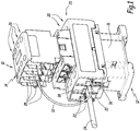
- the electrical system 10 shown in figure 1 comprises an electrical switching device 12, such as a contactor, and an auxiliary device 14 electrically coupled to the switching device 12.
- an electrical switching device 12 such as a contactor
- auxiliary device 14 electrically coupled to the switching device 12.
- the switching device 12 is a three-phase contactor 12 and comprises a housing 16, three first connection terminals 20 for input of a current, also called “first input terminals”, and three first connection terminals 22 for output. current, also called “first output terminals”.
- the contactor 12 is known per se and comprises a control member, not shown, capable of interrupting the flow of current between the first input 20 and output 22 terminals, that is to say between electrical conductors 24 of power, only one of which is represented in the figure 1 , respectively connected to the first input terminals 20 and to the second output terminals 22.
- the auxiliary apparatus 14 comprises four second input connection terminals 26 and four second output connection terminals 28.
- the auxiliary apparatus 14 is suitable for monitoring the operation of the switching device 12.
- the auxiliary apparatus 14 is used. , for example, suitable for measuring the current flowing through the first input 20 and output 22 terminals or for measuring the temperature of the first input 20 and output 22 terminals.
- the auxiliary device 14 comprises a calculation member , not shown, suitable for measuring the electric power and the electric energy at the level of each first input 20 and output 22 connection terminal.
- the auxiliary device 14 is generally suitable for communicating, via a wireless link or in wired variant, with a data concentrator, not shown.
- each of its first input terminal 20 which is connected, via a respective electric cable 32, to one of the corresponding second input terminals 26 and, on the other hand, each of its first output terminals 22 which is connected, via a respective electric cable 32, to one of the corresponding second output terminals 28.
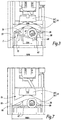
- Each first input 20 and output 22 terminal comprises a means 34, visible at the figure 2 , connection on itself of the electric cables 32 and the electric power conductors 24.
- the first input 20 and output 22 terminals each comprise a housing 36 for receiving an electric cable 32 and an electric conductor 24.
- Each electrical power conductor 24 is connected either to one of the first input terminals 20 or to one of the first output terminals 22. More precisely, each electrical power conductor 24 connected to one of the first terminals d The input 20 is electrically connected, via the contactor 12, to the electrical power conductor 24 connected to the corresponding first output terminal 22. Each electrical conductor 24 comprises an end portion 38 suitable for being inserted into the corresponding first connection terminal 20, 22.
- Each electric cable 32 comprises a resistive wire 42, a first connection end 44 provided with a heat-shrinkable sleeve 46 and a first connection member 47 to one of the first connection terminals 20, 22, as well as a second connection end 48 also provided with a heat-shrinkable sleeve 50 and with a second member 52 for connection to one of the second connection terminals 26, 28.
- each electric cable 32 extends between one of the first terminals input 20, or output 22 connection and respectively one of the second input 26, or output 28, corresponding terminals.
- connection means 34 is suitable for maintaining the connection between the corresponding electrical power conductor 24 and the corresponding first connection terminal 20, 22.
- Each connection means 34 comprises a screw 54 associated with a bracket 56.
- the housing 36 is suitable for receiving the first connection member 47 and the end part 38 and comprises two side walls 58, 59 between which extends a connection area 60.
- the side walls 58, 59 are perpendicular to the connection area. 60.
- the first connection member 47 corresponds to a terminal 47 which comprises a zone 64 for connecting the resistive wire 42 and a base 66.
- the terminal 47 is obtained, for example, by bending and cutting a metal plate.
- the terminal 47 extends along a longitudinal axis X47.
- the screw 54 and the bracket 56 are suitable for exerting a pressure force on the terminal 47 and the end part 38, in order to maintain an electrical contact between the connection pad 60, the end part 38 and the terminal 47.
- the screw 54 is suitable for being screwed or unscrewed in order to keep the corresponding electrical power conductor 24 electrically connected to the corresponding connection area 60 or respectively in order to disconnect the corresponding electrical power conductor 24 from the corresponding connection area 60 .
- the bracket 56 and the connection pad 60 are distant from each other and form a space E for receiving the terminal 47 and the electrical power conductor 24.
- connection pad 60 includes a hole 65 for receiving the screw 54.
- connection zone 64 is of suitable shape to maintain an electrical connection between the base 66 and the resistive wire 42.
- the terminal 47 and more precisely its base 66 is plastically deformable between two configurations, more precisely from an initial configuration presented to figures 2 to 6 to a connection configuration to the corresponding first connection terminal 20, 22, shown in figures 7 and 8 .
- the base 66 comprises a first part 68 and a second part 70.
- the base 66 also comprises an orifice 72 for passage of the screw 54 defined between the first 68 and second 70 parts.
- the first 68 and second 70 parts respectively comprise a first lateral side 74 and a second lateral side 76, which belong to a first plane P of the terminal 47 and define this first plane P.
- the first and second lateral sides 74, 76 s' extend generally along the longitudinal axis X47.
- the distance between the two lateral sides 74, 76, when the terminal is in the initial configuration, has a first value D74i which is less than its value D74c when the terminal is in the connection configuration.
- the first lateral side 74 is opposite one 59 of the two side walls, while the second lateral side 76 is opposite the other 58 side wall.
- the first 68 and second 70 parts also each include a first 78 and a second 80 fins which define between them, facing the orifice 72, a slot 82.
- a first angle ⁇ 1 measured between the first 68 and second 70 parts, on the side of the first plane P, is between 90 ° and 170 °, preferably between 120 ° and 150 °.
- the corresponding base 66 When the terminal 47 is in its initial configuration and is inserted into one of the first connection terminals 20, 22, the corresponding base 66 has, as shown in figure 3 , its edge 84 oriented towards the connection pad 60 and its lateral sides 74, 76 oriented towards the yoke 56. In other words, the base 66 has its edge 84 which is closer to the connection pad 60 than its lateral sides 74, 76.
- the first angle ⁇ 1 is equal to 180 ° with a margin of error of plus or minus 5 °.
- the first 68 and second 70 parts are positioned against the connection pad 60 and extend parallel or almost parallel to within less than 5 °, to the connection pad 60 and to the foreground P.
- the orifice 72 is a through hole aligned with the hole in the connection pad 60 when the terminal 47 is connected to the connection pad 60.
- the first 74 and second 76 lateral sides each comprise two elements 86 projecting from the remainder of the base 66 and from the corresponding lateral side 74, 76.
- the projecting elements 86 are oriented respectively in the direction of the side walls 59, 58, when the terminal 47 is connected to the connection pad 60.
- the first 78 and second 80 fins are inclined relative to the first plane P and the slot 82 corresponds to an access slot to the orifice for the connection means 34, more precisely for the screw 54.
- the minimum width of the slot 82 measured parallel to the first plane P and perpendicular to one of the lateral sides 74, 76 has, in the initial configuration, a value W82i greater than the diameter D54 of the screw.
- a second angle ⁇ 2 between each fin 78, 80 and the first plane P, measured on the side of the plane P is between 20 ° and 70 °, preferably between 40 ° and 60 °.
- the first 78 and second 80 fins are suitable for being flattened by the stirrup 56 during the plastic deformation of the terminal during its passage from the initial configuration to the connection configuration.
- the minimum width of the slot 82 measured parallel to the first plane P and perpendicular to one of the lateral sides 74, 76, has a value W82c less than the diameter of the screw D54.
- the second angle ⁇ 2 is between 0 ° and 10 °.
- the width of the base 66, measured in the initial configuration, at the level of each projecting element 86, parallel to the plane P and perpendicular to the lateral side 74, 76 corresponding, has a value W66i less than or equal to the distance D58 measured between the two side walls 58, 59, when the terminal 47 is connected to the first connection terminal 20, 22, at the level of the corresponding projecting element 86 and perpendicular to the corresponding side wall 58, 59.
- the width of the base 66 measured in the connection configuration of the terminal 47, at each protruding element 86, parallel to the plane P and perpendicular to the corresponding lateral side 74, 76, has a value W66c greater than the distance D58 between the two side walls 58, 59.
- the projecting elements 86 are suitable for being inserted into the side walls 58, 59, in the connection configuration of the terminal 47, since the value W66c is greater than the distance D58.
- the projecting elements 86 define claws suitable for being inserted into the corresponding side wall 58, 59 when the terminal 47 is deformed in the connection configuration.
- the protruding elements 86 are positioned at four corners formed by the base 66.
- each protruding member 86 measured perpendicular to the corresponding lateral side 74, 76 has, for example, a value W86 of less than 3 mm, preferably between 0.4 mm and 1.2 mm.
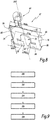
- FIG 8 a flowchart of a method of connecting the electric cable 32 and one of the electric power conductors 24 to one of the first connection terminals 20, 22 is shown.
- the terminal 47 is positioned on the corresponding first connection terminal 20, 22 in order to be connected to the latter. More precisely, the fins 78, 82 are brought into contact with the connection pad 60 and the projecting elements 86 are oriented towards the yoke 56.
- the terminal 47 is inserted at the level of the corresponding first connection terminal 20, 22, so that the screw 54 is positioned in the hole 72. More precisely, the screw 54 is already installed and disposed in the hole 65 and the terminal 47 is inserted into the corresponding connection terminal 20, 22, so that the screw 54 passes through slot 82 and is found in hole 72.
- the terminal 47 and more precisely its base 66, is flattened.
- the connection means 34 exert a pressure force on the base 66 in order to plastically deform the terminal from its initial configuration to its connection configuration.
- an operation of screwing the screw 54 is carried out, so that the yoke 56 moves in the direction of the connection pad 60 and flattens the base 66, that is to say the first 68 and second 70 parts.
- the protruding elements 86 are inserted into or scratch the corresponding side walls 58, 59 and the terminal 47 is thus immovably immobilized to the corresponding first connection terminal 20, 22.
- the terminal 47 is generally parallel to the connection pad 60 and flattened at the bottom of the first connection terminal 20, 22, that is to say against the connection pad 60.
- the fins 78, 80 are also flattened so as to reduce the minimum width of the slot 82 and to prevent any tearing of the terminal 47 relative to the first connection terminal 20, 22 corresponding.
- the electric cable 32 intended to be connected to the corresponding first connection terminal 20, 22 via its terminal 47, is also connected at its second end 48, via the second member connection 52 to the corresponding second connection terminal 26, 28.
- the screw 54 is unscrewed and the caliper 56 moves in a direction opposite to the connection pad 60.
- the space E is suitable for receiving the corresponding electric power conductor 24. More precisely, the receiving space E is formed between, on the one hand, the connection pad 60 and the terminal 47 and, on the other hand, the yoke 56.
- steps 100, 102 and 104 are carried out for each first connection terminal 20, 22 and following step 104 an operator has the electrical system 10, which he will install in an electrical installation between the electrical power conductors. 24.
- the electrical power conductor 24 and more precisely, the terminal part 38 is inserted into the reception space E, in order to be connected to the corresponding first connection terminal 20, 22.
- an operation of screwing the screw 54 is carried out in order to move the caliper 56 towards the connection area 60 and the terminal 47 and to keep the end part 38 connected to the connection area. 60 and wedged between the caliper 56 and the terminal 47.
- the fact that in the initial configuration of the terminal 47, the first 68 and second 70 parts are inclined, allows, during the deformation of the terminal in the connection configuration, that the projecting elements 86 come to exert a pressure force against the corresponding side walls 58, 59 and fit into these walls, knowing that the walls 58, 59 are generally made of plastic material.
- the inclination of the first 78 and second 80 fins makes it possible to form the slot 82 which is suitable, in the initial configuration of the terminal 47, to allow the screw 54 to pass so that the latter is positioned in the orifice 72. Indeed, the screw 54 is in place in each first connection terminal 20, 22, prior to the connection of the terminal 47 to the corresponding connection pad 60.
- the fact that the first 78 and second 80 fins are inclined makes it possible, during the deformation of the terminal 47 in the connection configuration, to reduce the width of the slot 82 in order to trap the screw 54 in the orifice 72 and to prevent any disconnection of the terminal 47 from the corresponding first connection terminal 20, 22.
- the flattening of the terminal 47 is guaranteed, which allows, following the operation unscrewing 104, to leave the space E between the connection pad 60 and the bracket 56.
- the volume of the space E is optimized, which makes it possible to facilitate access to the corresponding first connection terminal 20, 22 , following the connection of the terminal 47.
- the space E makes it possible to facilitate the connection of the electrical power conductor 24, that is to say of its terminal part 38, to the first corresponding connection terminal 20, 22. Since the connection of the electrical conductor 24 is facilitated and the terminal is flattened against the corresponding connection pad 60, the quality of the electrical contact between the connection pad 60, the terminal 47 and the electrical power conductor 24 is guaranteed and improved.
- first 78 and second 80 fins, as well as the projecting elements 86 ensure that the terminal 47 is immovable with respect to the corresponding first connection terminal 20, 22, in order to guarantee the connection between the auxiliary device 14 and the contactor 12.
- the resistive wires 42 cannot be dismantled and thus the connection between the switching device 12 and the auxiliary device 14 is guaranteed non-removable by the operator.
- the electrical system 10 presented at the figure 1 allows the control of three-phase capacitor banks, which favor the compensation of the reactive energy caused by strongly inductive loads in an electrical installation. More precisely, thanks to capacitor banks, the current drawn on an electrical network supplying the electrical installation is reduced.
- the resistive wires 42 make it possible to absorb current peaks passing through the first connection terminals 20, 22.
- the terminal 47 allows the connection of the electric cable 32 or of another type of electric cable to any type of connection terminal comprising a connection pad and side walls, similar to the connection pad 60 and to the side walls 58, 59.
- the switching device 12 is a single-phase contactor comprising a single or two first input terminals and a single or two first output terminals.
- the switching device 12 is, for example, a circuit breaker.
- only one of the first 68 and second 70 parts comprises a fin forming with the rest of the terminal the slot 82.
- each lateral side 74, 76 comprises a single projecting element 86.
- only one of the lateral sides 74, 76 comprises one or more projecting elements 86.
- protruding elements are arranged over the entire length of the lateral sides 74, 76 and the width of the protruding elements, measured perpendicular to the side walls 58, 59, varies increasing or decreasing along the lateral sides 74 , 76.
- the base 66 when the terminal 47 is inserted into one of the first connection terminals 20, 22, prior to its connection to one of the first connection terminals 20, 22, the base 66 corresponding to its edge 84 oriented towards the caliper 56 and its lateral sides 74, 76 in contact with the connection pad 60.
- connection means 34 can be of any type as long as it is suitable for applying a pressure force on the terminal 47, that is to say on the base 66, in order to deform the terminal 47 from its initial configuration towards its connection configuration.
Landscapes
- Details Of Connecting Devices For Male And Female Coupling (AREA)
- Connections Arranged To Contact A Plurality Of Conductors (AREA)
Claims (11)
- Kabelschuh (47) für eine elektrische Verbindung mit einer elektrischen Anschlussklemme (20, 22), wobei der Kabelschuh eine Verbindungszone (64) für ein elektrisches Kabel (42) und ein Basiselement (66) umfasst, wobei das Basiselement (66) eine Öffnung (72) für den Durchgang eines Verbindungsmittels (34) und zwei Seitenränder (74, 76) umfasst, die sich allgemein gemäß einer Längsachse (X47) des Kabelschuhs erstrecken, und das Basiselement (66) an mindestens eines seiner Seitenränder (74, 76) mindestens ein in Bezug auf den entsprechenden Seitenrand und den Rest des Basiselementes (66) vorspringendes Element (86) aufweist, dadurch gekennzeichnet, dass das Basiselement (66) einen ersten Bereich (68) und einen zweiten Bereich (70) umfasst, die jeweils einen der Seitenränder (74, 76) definieren, die beide in einer ersten Ebene (P) des Kabelschuhs (47) liegen, und dass der Kabelschuh (47) plastisch von einer Ausgangskonfiguration, in der der erste (68) und zweite (70) Bereich in Bezug auf die erste Ebene (P) jeweils geneigt sind, in eine Konfiguration des Verbindens mit der Anschlussklemme (20, 22) verformbar ist, und dass ein Abstand zwischen den zwei Seitenränder (74, 76) einen ersten Wert (D74i) aufweist, wenn der Kabelschuh in der Ausgangskonfiguration ist, der kleiner ist als ein zweiter Wert (D74c) dieses Abstandes, wenn der Kabelschuh in der Verbindungkonfiguration ist.
- Kabelschuh nach Anspruch 1, dadurch gekennzeichnet, dass das Basiselement (66) an jedem Seitenrand (74, 76) zwei in Bezug auf den Rest des Basiselementes (66) vorspringende Elemente (86) umfasst.
- Kabelschuh nach Anspruch 1 oder 2, dadurch gekennzeichnet, dass in der Verbindungskonfiguration das oder die vorspringenden Elemente (86) sich allgemein gemäß einer Richtung parallel zur ersten Ebene (P) und senkrecht zum entsprechenden Seitenrand (74, 76) erstrecken.
- Kabelschuh nach Anspruch 3, dadurch gekennzeichnet, dass:- in der Ausgangskonfiguration ein erster Winkel (α1), gemessen zwischen dem ersten (68) und zweiten (70) Bereich von der Seite der ersten Ebene, zwischen 90° und 170°, vorzugsweise zwischen 120° und 150° liegt und- in der Verbindungskonfiguration der erste Winkel (α1) gleich 180° mit einer Fehlerspanne plus oder minus 5° ist.
- Kabelschuh nach Anspruch 4, dadurch gekennzeichnet, dass:- mindestens einer des ersten (68) und zweiten (70) Bereichs einen Flügel (78, 80) umfasst, der mit dem Rest des Kabelschuhs einen Spalt (82) für den Zugang zur Öffnung (72) für das Verbindungsmittel (34) bildet,- in der Ausgangskonfiguration jeder Flügel (78, 80) in Bezug auf die erste Ebene (P) geneigt ist und ein zweiter Winkel (α2), gemessen zwischen jedem Flügel (78, 80) und der ersten Ebene (P) von der Seite der ersten Ebene (P), zwischen 20° und 70°, vorzugsweise zwischen 40° und 60° liegt und- in der Verbindungskonfiguration der zweite Winkel (α2) zwischen 0° und 10° liegt.
- Kabelschuh nach einem der Ansprüche 3 bis 5, dadurch gekennzeichnet, dass die Breite jedes vorspringenden Elementes (86), gemessen senkrecht zum entsprechenden Seitenrand (74, 76) und parallel zur ersten Ebene (P), einen Wert (W86) kleiner als 3 mm, vorzugsweise zwischen 0,4 mm und 1,2 mm aufweist.
- Elektrisches System (10), das mindestens eine elektrische Anschlussklemme (20, 22) und mindestens einen Kabelschuh (47) für eine elektrische Verbindung an die oder eine der elektrischen Anschlussklemmen umfasst, wobei jede Anschlussklemmen (20, 22) ein Verbindungsmittel (34) und einen Raum (36) zur Aufnahme des entsprechenden Kabelschuhs (47) umfasst und der Aufnahmeraum (36) eine Anschlussfläche (60) und zwei Seitenwände (58, 59) umfasst, zwischen denen sich die Anschlussfläche (60) erstreckt, dadurch gekennzeichnet, dass jeder Kabelschuh (47) nach einem der Ansprüche 1 bis 6 ausgebildet ist und dass das oder die vorspringenden Elemente (86) geeignet sind, bei der Verbindung jedes Kabelschuhs (47) mit der entsprechenden Anschlussklemme (20, 22) in eine der Seitenwände (58, 59) eingeführt zu werden.
- System nach Anspruch 7, dadurch gekennzeichnet, dass bei der Verbindung jedes Kabelschuhs (47) mit der entsprechenden Anschlussklemme (20, 22) das entsprechende Verbindungsmittel (34) geeignet ist, plastisch den Kabelschuh (47) von seiner Ausgangskonfiguration in seine Konfiguration des Verbindens mit der Anschlussklemme (20, 22) zu verformen.
- System nach Anspruch 8, dadurch gekennzeichnet, dass die Breite des Basiselementes, gemessen in der Ausgangskonfiguration an jedem vorspringenden Element (86) parallel zur ersten Ebene und senkrecht zum entsprechenden Seitenrand (74, 76), einen Wert (W66i) kleiner oder gleich dem Abstand (D58) zwischen den zwei Seitenwänden (58, 59), gemessen, wenn der Kabelschuh mit der Anschlussklemme (20, 22) verbunden ist, an dem entsprechenden vorspringenden Element (86) und senkrecht zur entsprechenden Seitenwand (58, 59) aufweist und dass die gleiche Breite des Basiselementes, gemessen in der Verbindungskonfiguration, einen Wert (W66c) größer als der Abstand (D58) zwischen den zwei Seitenwänden aufweist.
- System nach Anspruch 8 oder 9, bei dem jeder Kabelschuh nach Anspruch 5 ausgebildet ist, dadurch gekennzeichnet, dass das Verbindungsmittel einer Schraube umfasst, dass in der Ausgangskonfiguration des Kabelschuhs die minimale Breite des Spaltes (82) einen Wert (W82i) größer als der Durchmesser (D54) der Schraube (54) aufweist und dass in der Verbindungskonfiguration des Kabelschuhs die minimale Breite des Spaltes (82) einen Wert (W82c) kleiner als der Durchmesser (D54) der Schraube (54) aufweist.
- Verfahren zum Verbinden eines Kabelschuhs (47) für eine elektrische Verbindung mit einer elektrischen Anschlussklemme (20, 22), wobei der Kabelschuh eine Verbindungszone (64) für ein elektrisches Kabel (42) und ein Basiselement (66) umfasst, wobei das Basiselement (66) eine Öffnung (72) für den Durchgang eines Verbindungsmittels (34) und einen ersten Bereich (68) und einen zweiten Bereich (70), die jeweils einen Seitenrand (74, 76) definieren, umfasst, wobei die zwei Seitenränder (74, 76) sich allgemein gemäß einer Längsachse (X47) des Kabelschuhs erstrecken und beide in einer ersten Ebene (P) des Kabelschuhs (47) liegen, wobei die Anschlussklemme (20, 22) das Verbindungsmittel (34) und einen Raum (36) zur Aufnahme des Kabelschuhs (47) aufweist und der Aufnahmeraum (36) eine Verbindungsfläche (60) und zwei Seitenwände (58, 59) umfasst, zwischen denen sich die Anschlussfläche (60) erstreckt, wobei das Verfahren einen Schritt (102) des Verbindens des Kabelschuhs mit der Anschlussklemme (20, 22) umfasst, während dessen der Kabelschuh plastisch von einer Ausgangskonfiguration, in der der erste (68) und zweite (70) Bereich jeweils in Bezug auf die erste Ebene (P) geneigt sind, in eine Konfiguration des Verbindens mit der Anschlussklemme verformt wird und mindestens ein in Bezug auf einen Seitenrand des Basiselementes (66) vorspringendes Element (86) in eine der Seitenwände (58, 59) eingeführt wird, wobei ein Abstand zwischen den zwei Seitenränder (74, 76) einen ersten Wert (D74i) aufweist, wenn der Kabelschuh in der Ausgangskonfiguration ist, der kleiner ist als ein zweiter Wert (D74c) dieses Abstandes, wenn der Kabelschuh in der Verbindungskonfiguration ist.
Applications Claiming Priority (1)
| Application Number | Priority Date | Filing Date | Title |
|---|---|---|---|
| FR1362631A FR3015132B1 (fr) | 2013-12-13 | 2013-12-13 | Cosse de raccordement electrique a une borne de connexion, systeme electrique associe et procede de connexion d'une telle cosse a une borne de connexion |
Publications (2)
| Publication Number | Publication Date |
|---|---|
| EP2884591A1 EP2884591A1 (de) | 2015-06-17 |
| EP2884591B1 true EP2884591B1 (de) | 2020-09-23 |
Family
ID=50489229
Family Applications (1)
| Application Number | Title | Priority Date | Filing Date |
|---|---|---|---|
| EP14197686.0A Active EP2884591B1 (de) | 2013-12-13 | 2014-12-12 | Elektrischer kabelschuh für verbindungsklemme, entsprechendes elektrisches system und verbindungsverfahren eines solchen kabelschuhs an eine verbindungsklemme |
Country Status (3)
| Country | Link |
|---|---|
| EP (1) | EP2884591B1 (de) |
| CN (1) | CN204793320U (de) |
| FR (1) | FR3015132B1 (de) |
Family Cites Families (4)
| Publication number | Priority date | Publication date | Assignee | Title |
|---|---|---|---|---|
| US3344394A (en) * | 1966-05-16 | 1967-09-26 | Zinsco Electrical Products | Limited engagement lug assembly |
| US6242993B1 (en) * | 1995-03-13 | 2001-06-05 | Square D Company | Apparatus for use in arcing fault detection systems |
| BRPI0602294A (pt) * | 2006-06-14 | 2008-01-29 | Tyco Electronics Brasil Ltda | terminal idc com configuração fechada |
| DE102006049810B4 (de) * | 2006-10-17 | 2008-07-10 | Siemens Ag | Leistungsschalter, insbesondere Kompaktleistungsschalter, und Hilfsleiteranschluss für einen Leistungsschalter |
-
2013
- 2013-12-13 FR FR1362631A patent/FR3015132B1/fr not_active Expired - Fee Related
-
2014
- 2014-12-12 EP EP14197686.0A patent/EP2884591B1/de active Active
- 2014-12-15 CN CN201420794850.9U patent/CN204793320U/zh not_active Expired - Lifetime
Non-Patent Citations (1)
| Title |
|---|
| None * |
Also Published As
| Publication number | Publication date |
|---|---|
| FR3015132B1 (fr) | 2017-03-10 |
| EP2884591A1 (de) | 2015-06-17 |
| CN204793320U (zh) | 2015-11-18 |
| FR3015132A1 (fr) | 2015-06-19 |
Similar Documents
| Publication | Publication Date | Title |
|---|---|---|
| EP2521224B1 (de) | Schnellverbindungsvorrichtung für ein elektrisches Gerät | |
| FR3082669A1 (fr) | Clip metallique de connexion electrique d’un fil conducteur a un element metallique | |
| EP3000155A1 (de) | Elektrische vorrichtung mit in einem trägerelement untergebrachtem temperatursensor | |
| EP3314682B1 (de) | Elektrische energiespeichermodul | |
| FR2742918A1 (fr) | Dispositif de raccordement d'un conducteur exterieur tel un cable a une plage de contact d'un appareil electrique | |
| EP2937703B1 (de) | Vorrichtung zum Messen mindestens einer elektrischen Größe eines Stroms, der in einem Elektrogerät fließen soll, und Einheit, die eine solche Vorrichtung umfasst | |
| EP2884591B1 (de) | Elektrischer kabelschuh für verbindungsklemme, entsprechendes elektrisches system und verbindungsverfahren eines solchen kabelschuhs an eine verbindungsklemme | |
| FR2832862A3 (fr) | Connecteur de borne de batterie | |
| EP0926695B1 (de) | Differentialmoduls und elektrische Anschlussvorrichtung des Differentialmoduls an einem Schutzschalter | |
| AU2013404504B2 (en) | Cutout for use in electrical distribution network | |
| FR2963488A1 (fr) | Embout multipolaire de connexion electrique | |
| EP2662931B1 (de) | Anschlussschuh für isoliertes elektrisches Netzkabel, und Herstellungsverfahren dieses Anschlussschuhs | |
| EP3561968B1 (de) | Elektrisches anschlusssystem für einen spannungswandler | |
| FR3010838A1 (fr) | Borne a double systeme de raccordement electrique, en particulier pour un appareil de protection electrique basse tension, et appareil comportant une telle borne | |
| EP4343805A1 (de) | Schutzmodul für einen eingangsstrom eines elektrischen schaltgerätes vom nh-schmelzsicherungstyp | |
| EP1825278B1 (de) | Elektrische verbindungseinrichtung für einen polyphasen-stromzähler | |
| FR2860095A1 (fr) | Barre de raccordement electrique et dispositif de connexion adapte | |
| FR2990793A1 (fr) | Disjoncteur a boitier moule | |
| FR2786612A1 (fr) | Dispositif de raccordement electrique entre un systeme a barres et plusieurs cables conducteurs | |
| EP3435398B1 (de) | Elektrisches differentialschutzgerät | |
| BE1010987A3 (fr) | Dispositif de protection automatique contre les surcourants, du type a detente, avec fonction de mise a la masse. | |
| EP1450440A1 (de) | Elektrische Verbindungseinrichtung insbesondere zwischen einem Schuttschalter und einem Differentialmodul | |
| EP4343799A1 (de) | Stromumwandlungsmodul für eine elektrische schaltanlage vom nh-schmelzsicherungstyp | |
| FR3156255A1 (fr) | Appareillage de protection à coupure électronique | |
| EP3599629A1 (de) | Elektrische trennschaltervorrichtung für fahrzeug und entsprechendes fahrzeug |
Legal Events
| Date | Code | Title | Description |
|---|---|---|---|
| PUAI | Public reference made under article 153(3) epc to a published international application that has entered the european phase |
Free format text: ORIGINAL CODE: 0009012 |
|
| 17P | Request for examination filed |
Effective date: 20141212 |
|
| AK | Designated contracting states |
Kind code of ref document: A1 Designated state(s): AL AT BE BG CH CY CZ DE DK EE ES FI FR GB GR HR HU IE IS IT LI LT LU LV MC MK MT NL NO PL PT RO RS SE SI SK SM TR |
|
| AX | Request for extension of the european patent |
Extension state: BA ME |
|
| R17P | Request for examination filed (corrected) |
Effective date: 20150803 |
|
| RBV | Designated contracting states (corrected) |
Designated state(s): AL AT BE BG CH CY CZ DE DK EE ES FI FR GB GR HR HU IE IS IT LI LT LU LV MC MK MT NL NO PL PT RO RS SE SI SK SM TR |
|
| STAA | Information on the status of an ep patent application or granted ep patent |
Free format text: STATUS: EXAMINATION IS IN PROGRESS |
|
| 17Q | First examination report despatched |
Effective date: 20170904 |
|
| GRAP | Despatch of communication of intention to grant a patent |
Free format text: ORIGINAL CODE: EPIDOSNIGR1 |
|
| STAA | Information on the status of an ep patent application or granted ep patent |
Free format text: STATUS: GRANT OF PATENT IS INTENDED |
|
| INTG | Intention to grant announced |
Effective date: 20200528 |
|
| GRAS | Grant fee paid |
Free format text: ORIGINAL CODE: EPIDOSNIGR3 |
|
| GRAA | (expected) grant |
Free format text: ORIGINAL CODE: 0009210 |
|
| STAA | Information on the status of an ep patent application or granted ep patent |
Free format text: STATUS: THE PATENT HAS BEEN GRANTED |
|
| AK | Designated contracting states |
Kind code of ref document: B1 Designated state(s): AL AT BE BG CH CY CZ DE DK EE ES FI FR GB GR HR HU IE IS IT LI LT LU LV MC MK MT NL NO PL PT RO RS SE SI SK SM TR |
|
| REG | Reference to a national code |
Ref country code: GB Ref legal event code: FG4D Free format text: NOT ENGLISH |
|
| REG | Reference to a national code |
Ref country code: CH Ref legal event code: EP |
|
| REG | Reference to a national code |
Ref country code: DE Ref legal event code: R096 Ref document number: 602014070432 Country of ref document: DE |
|
| REG | Reference to a national code |
Ref country code: IE Ref legal event code: FG4D Free format text: LANGUAGE OF EP DOCUMENT: FRENCH |
|
| REG | Reference to a national code |
Ref country code: AT Ref legal event code: REF Ref document number: 1317326 Country of ref document: AT Kind code of ref document: T Effective date: 20201015 |
|
| PG25 | Lapsed in a contracting state [announced via postgrant information from national office to epo] |
Ref country code: GR Free format text: LAPSE BECAUSE OF FAILURE TO SUBMIT A TRANSLATION OF THE DESCRIPTION OR TO PAY THE FEE WITHIN THE PRESCRIBED TIME-LIMIT Effective date: 20201224 Ref country code: BG Free format text: LAPSE BECAUSE OF FAILURE TO SUBMIT A TRANSLATION OF THE DESCRIPTION OR TO PAY THE FEE WITHIN THE PRESCRIBED TIME-LIMIT Effective date: 20201223 Ref country code: NO Free format text: LAPSE BECAUSE OF FAILURE TO SUBMIT A TRANSLATION OF THE DESCRIPTION OR TO PAY THE FEE WITHIN THE PRESCRIBED TIME-LIMIT Effective date: 20201223 Ref country code: SE Free format text: LAPSE BECAUSE OF FAILURE TO SUBMIT A TRANSLATION OF THE DESCRIPTION OR TO PAY THE FEE WITHIN THE PRESCRIBED TIME-LIMIT Effective date: 20200923 Ref country code: HR Free format text: LAPSE BECAUSE OF FAILURE TO SUBMIT A TRANSLATION OF THE DESCRIPTION OR TO PAY THE FEE WITHIN THE PRESCRIBED TIME-LIMIT Effective date: 20200923 Ref country code: FI Free format text: LAPSE BECAUSE OF FAILURE TO SUBMIT A TRANSLATION OF THE DESCRIPTION OR TO PAY THE FEE WITHIN THE PRESCRIBED TIME-LIMIT Effective date: 20200923 |
|
| REG | Reference to a national code |
Ref country code: AT Ref legal event code: MK05 Ref document number: 1317326 Country of ref document: AT Kind code of ref document: T Effective date: 20200923 |
|
| PG25 | Lapsed in a contracting state [announced via postgrant information from national office to epo] |
Ref country code: LV Free format text: LAPSE BECAUSE OF FAILURE TO SUBMIT A TRANSLATION OF THE DESCRIPTION OR TO PAY THE FEE WITHIN THE PRESCRIBED TIME-LIMIT Effective date: 20200923 Ref country code: RS Free format text: LAPSE BECAUSE OF FAILURE TO SUBMIT A TRANSLATION OF THE DESCRIPTION OR TO PAY THE FEE WITHIN THE PRESCRIBED TIME-LIMIT Effective date: 20200923 |
|
| REG | Reference to a national code |
Ref country code: NL Ref legal event code: MP Effective date: 20200923 |
|
| REG | Reference to a national code |
Ref country code: LT Ref legal event code: MG4D |
|
| PG25 | Lapsed in a contracting state [announced via postgrant information from national office to epo] |
Ref country code: SM Free format text: LAPSE BECAUSE OF FAILURE TO SUBMIT A TRANSLATION OF THE DESCRIPTION OR TO PAY THE FEE WITHIN THE PRESCRIBED TIME-LIMIT Effective date: 20200923 Ref country code: RO Free format text: LAPSE BECAUSE OF FAILURE TO SUBMIT A TRANSLATION OF THE DESCRIPTION OR TO PAY THE FEE WITHIN THE PRESCRIBED TIME-LIMIT Effective date: 20200923 Ref country code: LT Free format text: LAPSE BECAUSE OF FAILURE TO SUBMIT A TRANSLATION OF THE DESCRIPTION OR TO PAY THE FEE WITHIN THE PRESCRIBED TIME-LIMIT Effective date: 20200923 Ref country code: NL Free format text: LAPSE BECAUSE OF FAILURE TO SUBMIT A TRANSLATION OF THE DESCRIPTION OR TO PAY THE FEE WITHIN THE PRESCRIBED TIME-LIMIT Effective date: 20200923 Ref country code: PT Free format text: LAPSE BECAUSE OF FAILURE TO SUBMIT A TRANSLATION OF THE DESCRIPTION OR TO PAY THE FEE WITHIN THE PRESCRIBED TIME-LIMIT Effective date: 20210125 Ref country code: CZ Free format text: LAPSE BECAUSE OF FAILURE TO SUBMIT A TRANSLATION OF THE DESCRIPTION OR TO PAY THE FEE WITHIN THE PRESCRIBED TIME-LIMIT Effective date: 20200923 Ref country code: EE Free format text: LAPSE BECAUSE OF FAILURE TO SUBMIT A TRANSLATION OF THE DESCRIPTION OR TO PAY THE FEE WITHIN THE PRESCRIBED TIME-LIMIT Effective date: 20200923 |
|
| PG25 | Lapsed in a contracting state [announced via postgrant information from national office to epo] |
Ref country code: IS Free format text: LAPSE BECAUSE OF FAILURE TO SUBMIT A TRANSLATION OF THE DESCRIPTION OR TO PAY THE FEE WITHIN THE PRESCRIBED TIME-LIMIT Effective date: 20210123 Ref country code: PL Free format text: LAPSE BECAUSE OF FAILURE TO SUBMIT A TRANSLATION OF THE DESCRIPTION OR TO PAY THE FEE WITHIN THE PRESCRIBED TIME-LIMIT Effective date: 20200923 Ref country code: ES Free format text: LAPSE BECAUSE OF FAILURE TO SUBMIT A TRANSLATION OF THE DESCRIPTION OR TO PAY THE FEE WITHIN THE PRESCRIBED TIME-LIMIT Effective date: 20200923 Ref country code: AT Free format text: LAPSE BECAUSE OF FAILURE TO SUBMIT A TRANSLATION OF THE DESCRIPTION OR TO PAY THE FEE WITHIN THE PRESCRIBED TIME-LIMIT Effective date: 20200923 Ref country code: AL Free format text: LAPSE BECAUSE OF FAILURE TO SUBMIT A TRANSLATION OF THE DESCRIPTION OR TO PAY THE FEE WITHIN THE PRESCRIBED TIME-LIMIT Effective date: 20200923 |
|
| REG | Reference to a national code |
Ref country code: DE Ref legal event code: R097 Ref document number: 602014070432 Country of ref document: DE |
|
| PG25 | Lapsed in a contracting state [announced via postgrant information from national office to epo] |
Ref country code: SK Free format text: LAPSE BECAUSE OF FAILURE TO SUBMIT A TRANSLATION OF THE DESCRIPTION OR TO PAY THE FEE WITHIN THE PRESCRIBED TIME-LIMIT Effective date: 20200923 |
|
| PLBE | No opposition filed within time limit |
Free format text: ORIGINAL CODE: 0009261 |
|
| REG | Reference to a national code |
Ref country code: CH Ref legal event code: PL |
|
| STAA | Information on the status of an ep patent application or granted ep patent |
Free format text: STATUS: NO OPPOSITION FILED WITHIN TIME LIMIT |
|
| GBPC | Gb: european patent ceased through non-payment of renewal fee |
Effective date: 20201223 |
|
| PG25 | Lapsed in a contracting state [announced via postgrant information from national office to epo] |
Ref country code: SI Free format text: LAPSE BECAUSE OF FAILURE TO SUBMIT A TRANSLATION OF THE DESCRIPTION OR TO PAY THE FEE WITHIN THE PRESCRIBED TIME-LIMIT Effective date: 20200923 Ref country code: DK Free format text: LAPSE BECAUSE OF FAILURE TO SUBMIT A TRANSLATION OF THE DESCRIPTION OR TO PAY THE FEE WITHIN THE PRESCRIBED TIME-LIMIT Effective date: 20200923 Ref country code: MC Free format text: LAPSE BECAUSE OF FAILURE TO SUBMIT A TRANSLATION OF THE DESCRIPTION OR TO PAY THE FEE WITHIN THE PRESCRIBED TIME-LIMIT Effective date: 20200923 |
|
| 26N | No opposition filed |
Effective date: 20210624 |
|
| REG | Reference to a national code |
Ref country code: BE Ref legal event code: MM Effective date: 20201231 |
|
| PG25 | Lapsed in a contracting state [announced via postgrant information from national office to epo] |
Ref country code: IT Free format text: LAPSE BECAUSE OF FAILURE TO SUBMIT A TRANSLATION OF THE DESCRIPTION OR TO PAY THE FEE WITHIN THE PRESCRIBED TIME-LIMIT Effective date: 20200923 Ref country code: IE Free format text: LAPSE BECAUSE OF NON-PAYMENT OF DUE FEES Effective date: 20201212 Ref country code: LU Free format text: LAPSE BECAUSE OF NON-PAYMENT OF DUE FEES Effective date: 20201212 |
|
| PG25 | Lapsed in a contracting state [announced via postgrant information from national office to epo] |
Ref country code: GB Free format text: LAPSE BECAUSE OF NON-PAYMENT OF DUE FEES Effective date: 20201223 Ref country code: CH Free format text: LAPSE BECAUSE OF NON-PAYMENT OF DUE FEES Effective date: 20201231 Ref country code: LI Free format text: LAPSE BECAUSE OF NON-PAYMENT OF DUE FEES Effective date: 20201231 |
|
| PG25 | Lapsed in a contracting state [announced via postgrant information from national office to epo] |
Ref country code: IS Free format text: LAPSE BECAUSE OF FAILURE TO SUBMIT A TRANSLATION OF THE DESCRIPTION OR TO PAY THE FEE WITHIN THE PRESCRIBED TIME-LIMIT Effective date: 20210123 Ref country code: MT Free format text: LAPSE BECAUSE OF FAILURE TO SUBMIT A TRANSLATION OF THE DESCRIPTION OR TO PAY THE FEE WITHIN THE PRESCRIBED TIME-LIMIT Effective date: 20200923 Ref country code: CY Free format text: LAPSE BECAUSE OF FAILURE TO SUBMIT A TRANSLATION OF THE DESCRIPTION OR TO PAY THE FEE WITHIN THE PRESCRIBED TIME-LIMIT Effective date: 20200923 |
|
| PG25 | Lapsed in a contracting state [announced via postgrant information from national office to epo] |
Ref country code: MK Free format text: LAPSE BECAUSE OF FAILURE TO SUBMIT A TRANSLATION OF THE DESCRIPTION OR TO PAY THE FEE WITHIN THE PRESCRIBED TIME-LIMIT Effective date: 20200923 |
|
| PG25 | Lapsed in a contracting state [announced via postgrant information from national office to epo] |
Ref country code: BE Free format text: LAPSE BECAUSE OF NON-PAYMENT OF DUE FEES Effective date: 20201231 |
|
| PGFP | Annual fee paid to national office [announced via postgrant information from national office to epo] |
Ref country code: TR Payment date: 20241202 Year of fee payment: 11 |
|
| PGFP | Annual fee paid to national office [announced via postgrant information from national office to epo] |
Ref country code: DE Payment date: 20241227 Year of fee payment: 11 |
|
| PGFP | Annual fee paid to national office [announced via postgrant information from national office to epo] |
Ref country code: FR Payment date: 20251230 Year of fee payment: 12 |