EP2884591A1 - Lug for electrical connection to a connection terminal, associated electrical system and method for connecting such a lug to a connection terminal - Google Patents
Lug for electrical connection to a connection terminal, associated electrical system and method for connecting such a lug to a connection terminal Download PDFInfo
- Publication number
- EP2884591A1 EP2884591A1 EP14197686.0A EP14197686A EP2884591A1 EP 2884591 A1 EP2884591 A1 EP 2884591A1 EP 14197686 A EP14197686 A EP 14197686A EP 2884591 A1 EP2884591 A1 EP 2884591A1
- Authority
- EP
- European Patent Office
- Prior art keywords
- connection
- terminal
- lug
- configuration
- base
- Prior art date
- Legal status (The legal status is an assumption and is not a legal conclusion. Google has not performed a legal analysis and makes no representation as to the accuracy of the status listed.)
- Granted
Links
Images


Classifications
-
- H—ELECTRICITY
- H01—ELECTRIC ELEMENTS
- H01R—ELECTRICALLY-CONDUCTIVE CONNECTIONS; STRUCTURAL ASSOCIATIONS OF A PLURALITY OF MUTUALLY-INSULATED ELECTRICAL CONNECTING ELEMENTS; COUPLING DEVICES; CURRENT COLLECTORS
- H01R13/00—Details of coupling devices of the kinds covered by groups H01R12/70 or H01R24/00 - H01R33/00
- H01R13/02—Contact members
- H01R13/10—Sockets for co-operation with pins or blades
- H01R13/11—Resilient sockets
- H01R13/112—Resilient sockets forked sockets having two legs
-
- H—ELECTRICITY
- H01—ELECTRIC ELEMENTS
- H01R—ELECTRICALLY-CONDUCTIVE CONNECTIONS; STRUCTURAL ASSOCIATIONS OF A PLURALITY OF MUTUALLY-INSULATED ELECTRICAL CONNECTING ELEMENTS; COUPLING DEVICES; CURRENT COLLECTORS
- H01R13/00—Details of coupling devices of the kinds covered by groups H01R12/70 or H01R24/00 - H01R33/00
- H01R13/40—Securing contact members in or to a base or case; Insulating of contact members
- H01R13/405—Securing in non-demountable manner, e.g. moulding, riveting
- H01R13/41—Securing in non-demountable manner, e.g. moulding, riveting by frictional grip in grommet, panel or base
-
- H—ELECTRICITY
- H01—ELECTRIC ELEMENTS
- H01R—ELECTRICALLY-CONDUCTIVE CONNECTIONS; STRUCTURAL ASSOCIATIONS OF A PLURALITY OF MUTUALLY-INSULATED ELECTRICAL CONNECTING ELEMENTS; COUPLING DEVICES; CURRENT COLLECTORS
- H01R4/00—Electrically-conductive connections between two or more conductive members in direct contact, i.e. touching one another; Means for effecting or maintaining such contact; Electrically-conductive connections having two or more spaced connecting locations for conductors and using contact members penetrating insulation
- H01R4/28—Clamped connections, spring connections
- H01R4/30—Clamped connections, spring connections utilising a screw or nut clamping member
- H01R4/34—Conductive members located under head of screw
-
- H—ELECTRICITY
- H01—ELECTRIC ELEMENTS
- H01R—ELECTRICALLY-CONDUCTIVE CONNECTIONS; STRUCTURAL ASSOCIATIONS OF A PLURALITY OF MUTUALLY-INSULATED ELECTRICAL CONNECTING ELEMENTS; COUPLING DEVICES; CURRENT COLLECTORS
- H01R4/00—Electrically-conductive connections between two or more conductive members in direct contact, i.e. touching one another; Means for effecting or maintaining such contact; Electrically-conductive connections having two or more spaced connecting locations for conductors and using contact members penetrating insulation
- H01R4/28—Clamped connections, spring connections
- H01R4/38—Clamped connections, spring connections utilising a clamping member acted on by screw or nut
- H01R4/44—Clamping areas on both sides of screw
-
- H—ELECTRICITY
- H01—ELECTRIC ELEMENTS
- H01R—ELECTRICALLY-CONDUCTIVE CONNECTIONS; STRUCTURAL ASSOCIATIONS OF A PLURALITY OF MUTUALLY-INSULATED ELECTRICAL CONNECTING ELEMENTS; COUPLING DEVICES; CURRENT COLLECTORS
- H01R11/00—Individual connecting elements providing two or more spaced connecting locations for conductive members which are, or may be, thereby interconnected, e.g. end pieces for wires or cables supported by the wire or cable and having means for facilitating electrical connection to some other wire, terminal, or conductive member, blocks of binding posts
- H01R11/11—End pieces or tapping pieces for wires, supported by the wire and for facilitating electrical connection to some other wire, terminal or conductive member
- H01R11/12—End pieces terminating in an eye, hook, or fork
Definitions
- the present invention relates to a lug for electrical connection to an electrical connection terminal, an electrical system comprising an electrical switching device and an auxiliary device connected to one another via an electric cable or cables provided with such a terminal lug. connection, and a method of connecting such a connection terminal to a connection terminal.
- a persistent challenge in the field of connections and more specifically the connection of a connection terminal to a connection terminal is to ensure optimum electrical contact between the terminal and the terminal connection, to ensure electrical contact quality.
- connection terminal for example as described in WO 2007/143805 A2
- a connecting lug comprising a terminal receiving means for connecting the lug to a connection terminal.
- the orifice is extended by a slot allowing insertion into the orifice of a screw belonging to the connection means.
- the connection means comprise the screw and a stirrup, whereas during the connection of the terminal to the connection terminal, the terminal is positioned in contact with the connection terminal, so that the screw goes through the slit and is found in the hole.
- connection terminal is intended to be connected, on the one hand, to an electrical cable comprising the terminal and, on the other hand, to an electrical power conductor, it is difficult to position the electrical power cable. in the connection terminal and to guarantee a high quality electrical contact of the terminal and the electrical power conductor with the connection range.
- the object of the invention is therefore to provide an electrical connection lug to a connection terminal allowing improved contact quality of the lug with the connection terminal, especially when an electric cable provided with the lug and a driver Power supply are connected to the connection terminal.
- the subject of the invention is an electrical connection terminal to an electrical connection terminal, the terminal comprising a connection zone to an electrical wire and a base, the base comprising a passage opening of a connection means. and two lateral sides extending generally along a longitudinal axis of the terminal.
- the base comprises on at least one of its lateral sides at least one element projecting from the corresponding lateral side and the rest of the base.
- the projecting elements are adapted to be inserted in the connection terminal and more precisely in the walls of the connection terminal, which makes it possible to connect the terminal to the connection terminal immovably and thus to guarantee an improved electrical contact quality.
- the irremovable holding of the terminal to the connection terminal makes it possible to avoid any unwanted disconnection, unwanted, of the terminal and therefore of an electrical conductor provided with the terminal, with respect to the connection terminal.
- the fact that the lug is connected irremovably also facilitates the connection of an electrical power conductor to the connection terminal, in addition to the connection of an electric cable with the lug.
- the invention also relates to an electrical system comprising at least one electrical connection terminal and at least one such electrical connection terminal to the one or one of the electrical connection terminals, each connection terminal comprising a connection means and a receiving housing of the corresponding lug, the housing comprising a connection pad and two side walls between which the connection pad extends.
- the projecting element or elements are adapted to be inserted in one of the side walls, during the connection of each lug to the corresponding connection terminal.
- the invention also relates to a method of connecting an electrical connection terminal to an electrical connection terminal, the terminal comprising a connection zone to an electrical wire and a base, the base comprising a passage opening of a connecting means and two lateral sides extending generally along a longitudinal axis of the terminal, the connection terminal comprising the connecting means and a receiving housing of the terminal, the housing comprising a connection pad and two side walls between which extends the connection range.
- the method comprises a step of connecting the terminal to the connection terminal, during which at least one element, projecting from a lateral side of the base, is inserted in one of the side walls.
- the electrical system 10 shown on the figure 1 comprises an electrical switching device 12, such as a contactor, and an auxiliary device 14 electrically coupled to the switching device 12.
- an electrical switching device 12 such as a contactor
- auxiliary device 14 electrically coupled to the switching device 12.
- the switching device 12 is a three-phase contactor 12 and comprises a housing 16, three first input terminals 20 of a current, also called “first input terminals”, and three first connection terminals 22 of the output. current, also called “first output terminals”.
- the contactor 12 is known per se and comprises a control device, not shown, capable of interrupting the flow of current between the first input and output terminals 22, that is to say between electrical conductors 24 of power, of which only one is represented at figure 1 connected respectively to the first input terminals 20 and the second output terminals 22.
- the auxiliary apparatus 14 comprises four second input connection terminals 26 and four second output connection terminals 28.
- the auxiliary apparatus 14 is able to monitor the operation of the switching device 12.
- the auxiliary apparatus 14 is for example, able to measure the current flowing through the first input and output terminals 22 or to measure the temperature of the first input and output terminals 22.
- the auxiliary device 14 comprises a computing device , not shown, adapted to measure the electrical power and the electrical energy at each first input terminal 20 and output terminal 22.
- the auxiliary device 14 is generally able to communicate, via a wireless link or in wired variant, with a data concentrator, not shown.
- each of its first input terminal 20 which is connected, via a respective electric cable 32, to one of the corresponding second input terminals 26 and, on the other hand, each of its first output terminal 22 which is connected, via a respective electric cable 32, to one of the corresponding second output terminals 28.
- Each first input terminal 20 and output terminal 22 comprises means 34, visible at the figure 2 connecting electrical cables 32 and electrical power conductors 24 to itself.
- the first input and output terminals 22 each comprise a housing 36 for receiving an electrical cable 32 and an electrical conductor 24.
- Each electrical power conductor 24 is connected either to one of the first input terminals 20 or to one of the first output terminals 22. More precisely, each electrical power conductor 24 connected to one of the first terminals input 20 is electrically connected, via switch 12, to the power conductor 24 connected to the corresponding first output terminal 22. Each electrical conductor 24 comprises an end portion 38 adapted to be inserted into the corresponding first connecting terminal 20, 22.
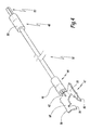
- Each electrical cable 32 comprises a resistive wire 42, a first connection end 44 provided with a heat-shrinkable sleeve 46 and a first connection member 47 to one of the first connection terminals 20, 22, as well as a second connection end 48 also provided with a heat-shrinkable sleeve 50 and a second member 52 for connection to one of the second connection terminals 26, 28.
- each electrical cable 32 extends between one of the first terminals 20, or output connection 22 and respectively one of the second input terminals 26, or output 28, corresponding.
- connection means 34 is adapted to maintain the connection between the corresponding power conductor 24 and the corresponding first connection terminal 20, 22.
- Each connection means 34 comprises a screw 54 associated with a stirrup 56.
- the housing 36 is adapted to receive the first connecting member 47 and the end portion 38 and comprises two side walls 58, 59 between which a connection pad 60 extends.
- the side walls 58, 59 are perpendicular to the connection pad 60.
- the first connecting member 47 corresponds to a terminal 47 which comprises a zone 64 for connecting the resistive wire 42 and a base 66.
- the lug 47 is obtained, for example, by folding and cutting a metal plate.
- the lug 47 extends along a longitudinal axis X47.
- the screw 54 and the stirrup 56 are able to exert a pressure force on the terminal 47 and the end portion 38, in order to maintain electrical contact between the connection pad 60, the terminal portion 38 and the pod 47.
- the screw 54 is adapted to be screwed or unscrewed in order to maintain the corresponding electrical power conductor 24 electrically connected to the corresponding connection pad 60 or respectively in order to disconnect the corresponding electrical power conductor 24 relative to the corresponding connection pad 60. .
- the stirrup 56 and the connection pad 60 are spaced from one another and form a receiving space E of the terminal 47 and the electrical power conductor 24.
- connection pad 60 includes a hole 65 for receiving the screw 54.
- the connecting zone 64 is shaped to maintain an electrical connection between the base 66 and the resistive wire 42.
- the terminal 47 and more precisely its base 66 is plastically deformable between two configurations, more precisely since an initial configuration presented to the Figures 2 to 6 to a connection configuration at the corresponding first connection terminal 20, 22, shown in FIGS. figures 7 and 8 .
- the base 66 includes a first portion 68 and a second portion 70.
- the base 66 also includes a hole 72 for the passage of the screw 54 defined between the first 68 and second 70 parts.
- the first 68 and second 70 parts respectively comprise a first lateral side 74 and a second lateral side 76, which belong to a first plane P of the lug 47 and define this first plane P.
- the first and second lateral sides 74, 76 are extend globally along the longitudinal axis X47.
- the distance between the two lateral sides 74, 76, when the lug is in initial configuration, has a first value D74i which is lower than its value D74c when the lug is in connection configuration.
- the first lateral side 74 is opposite one of the two side walls, while the second lateral side 76 is opposite the other 58 side wall.
- the first 68 and second 70 parts also each comprise a first 78 and a second 80 fins which delimit between them, opposite the orifice 72, a slot 82.
- a first angle ⁇ 1 measured between the first 68 and second 70 parts, on the side of the first plane P, is between 90 ° and 170 °, preferably between 120 ° and 150 °.
- the corresponding base 66 When the lug 47 is in its initial configuration and is inserted into one of the first connection terminals 20, 22, the corresponding base 66 has, as shown in FIG. figure 3 its edge 84 facing the connection pad 60 and its lateral sides 74, 76 In other words, the base 66 has its edge 84 which is closer to the connection pad 60 than its lateral sides 74, 76.
- the first angle ⁇ 1 is equal to 180 ° with a margin of error of plus or minus 5 °.
- the first 68 and second 70 parts are positioned against the connection pad 60 and extend parallel or almost parallel to less than 5 °, to the connection pad 60 and the foreground P.
- the orifice 72 is a through-hole aligned with the hole of the connection pad 60 when the lug 47 is connected to the connection pad 60.
- the first 74 and second 76 lateral sides each comprise two elements 86 projecting from the rest of the base 66 and the lateral side 74, 76 corresponding.
- the projecting elements 86 are respectively oriented towards the side walls 59, 58, when the lug 47 is connected to the connection pad 60.
- the first 78 and second fins 80 are inclined relative to the first plane P and the slot 82 corresponds to an access port slot for the connection means 34, specifically for the screw 54.
- the minimum width of the slot 82 measured parallel to the first plane P and perpendicular to one of the lateral sides 74, 76 has, in the initial configuration, a value W82i greater than the diameter D54 of the screw.
- a second angle ⁇ 2 between each fin 78, 80 and the first plane P, measured on the plane P side is between 20 ° and 70 °, preferably between 40 ° and 60 °.
- the first 78 and second 80 fins are adapted to be flattened by the stirrup 56 during the plastic deformation of the terminal during its transition from the initial configuration to the connection configuration.
- the minimum width of the slot 82 measured parallel to the first plane P and perpendicular to one of the lateral sides 74, 76, has a value W82c less than the diameter of the screw D54.
- the second angle ⁇ 2 is between 0 ° and 10 °.
- the width of the base 66, measured in initial configuration, at each projecting element 86, parallel to the plane P and perpendicular to the lateral side 74, 76 corresponding, has a value W66i less than or equal to the distance D58 measured between the two. side walls 58, 59, when the lug 47 is connected to the first connection terminal 20, 22, at the corresponding projecting element 86 and perpendicular to the corresponding side wall 58, 59.
- the width of the base 66 measured in connection configuration of the lug 47, at each projecting element 86, parallel to the plane P and perpendicular to the lateral side 74, 76 corresponding, has a value W66c greater than the distance D58 between the two side walls 58, 59.
- the projecting elements 86 are adapted to be inserted in the side walls 58, 59, in the connection configuration of the terminal 47, since the value W66c is greater than the distance D58.
- the projecting elements 86 define claws adapted to be inserted into the corresponding side wall 58, 59 when the lug 47 is deformed in connection configuration.
- the projecting elements 86 are positioned at four corners formed by the base 66.
- each projecting element 86 measured perpendicularly to the lateral side 74, 76 corresponding to, for example, a W86 value less than 3 mm, preferably between 0.4 mm and 1.2 mm.
- FIG 8 a flowchart of a method of connecting the electrical cable 32 and one of the power electrical conductors 24 to one of the first connection terminals 20, 22 is shown.
- a first step 100 the lug 47 is positioned on the corresponding first connection terminal 20, 22 in order to be connected thereto. More specifically, the fins 78, 82 are brought into contact with the connection pad 60 and the projecting elements 86 are oriented towards the bracket 56.
- the pod 47 is inserted at the first corresponding connection terminal 20, 22, so that the screw 54 is positioned in the orifice 72. More specifically, the screw 54 is already installed and disposed in the hole 65 and the lug 47 is inserted into the connection terminal 20, 22 corresponding, so that the 54 screws through the slot 82 and are found in the orifice 72.
- the terminal 47 and more precisely its base 66, is flattened.
- the connection means 34 exerts a pressure force on the base 66 to plastically deform the lug from its initial configuration to its connection configuration.
- a screwing operation of the screw 54 is performed, so that the stirrup 56 moves towards the connection pad 60 and flatten the base 66, that is to say the first 68 and second 70 parts.
- the projecting elements 86 are inserted into or scratch the corresponding side walls 58, 59 and the lug 47 is thus fixed irremovably to the corresponding first connection terminal 20, 22.
- the lug 47 is generally parallel to the connection pad 60 and flattened at the bottom of the first connection terminal 20, 22, that is to say against the connection pad 60.
- the fins 78, 80 are also flattened so as to reduce the width minimum of the slot 82 and to prevent tearing of the lug 47 relative to the corresponding first connection terminal 20, 22.
- the electric cable 32 intended to be connected to the corresponding first connection terminal 20, 22 via its lug 47, is also connected at its second end 48, via the second element connection 52 to the corresponding second connection terminal 26, 28.
- the screw 54 is unscrewed and the stirrup 56 moves in a direction opposite to the connection pad 60.
- the space E is adapted to receive the corresponding 24-wire power conductor. More precisely, the receiving space E is formed between, on the one hand, the connection pad 60 and the pad 47 and, on the other hand, the bracket 56.
- steps 100, 102 and 104 are performed for each first connection terminal 20, 22 and following step 104 an operator has the electrical system 10, which he will install in an electrical installation between the electrical power conductors 24.
- the electrical power conductor 24 and more precisely, the end portion 38 is inserted into the receiving space E, in order to be connected to the corresponding first connection terminal 20, 22.
- a screwing operation of the screw 54 is carried out in order to move the stirrup 56 towards the connection pad 60 and the lug 47 and to keep the end portion 38 connected to the connection pad 60 and wedged between the stirrup 56 and the lug 47.
- the inclination of the first 78 and second 80 fins makes it possible to form the slit 82 which is clean, in the initial configuration of the lug 47, to let the screw 54 pass so that it is positioned in the orifice 72. Indeed, the screw 54 is in place in each first connection terminal 20, 22, prior to the connection of the lug 47 on the corresponding connection pad 60. Moreover, the fact that the first 78 and second 80 fins are inclined allows, during the deformation of the lug 47 in the connection configuration, to reduce the width of the slot 82 to trap the screw 54 in the orifice 72 and prevent disconnection of the lug 47 of the corresponding first connection terminal 20, 22.
- the flattening of the lug 47 is guaranteed, which, following the operation, unscrewing 104, to leave the space E between the connection pad 60 and the stirrup 56.
- the volume of the space E is optimized, which makes it easier to access the corresponding first connection terminal 20, 22 after the connection of the terminal 47.
- the space E facilitates the connection of the electrical power conductor 24, that is to say from its end portion 38, to the corresponding first connection terminal 20, 22. Since the connection of the electrical conductor 24 is facilitated and that the lug is flat against the corresponding connection pad 60, the quality of the electrical contact between the connection pad 60, the lug 47 and the electrical power conductor 24 is guaranteed and improved.
- first 78 and second 80 fins, as well as the projecting elements 86, ensure that the lug 47 has a non-removable character with respect to the corresponding first connection terminal 20, 22, in order to guarantee the connection between the auxiliary device 14 and the contactor 12.
- the resistive son 42 are non-removable and thus the connection between the switching device 12 and the auxiliary device 14 is guaranteed to be removable by the operator.
- the electrical system 10 presented to the figure 1 allows the control of three-phase capacitor banks, which promote the compensation of the reactive energy caused by highly inductive loads in an electrical installation. More precisely, thanks to the capacitor banks, the current drawn on an electrical network supplying the electrical installation is reduced.
- the resistive son 42 can absorb current peaks passing through the first terminals 20,22.
- the lug 47 allows the connection of the electric cable 32 or another type of electrical cable to any type of connection terminal comprising a connection pad and side walls, similar to the connection pad 60 and the side walls 58, 59.
- the switching device 12 is a single-phase contactor comprising only one or two first input terminals and one or two first output terminals.
- the switching device 12 is, for example, a circuit breaker.
- only one of the first 68 and second 70 parts comprises a fin forming with the rest of the terminal slot 82.
- each lateral side 74, 76 comprises a single projecting element 86.
- only one of the lateral sides 74, 76 comprises one or more projecting elements 86.
- projecting elements are arranged along the entire length of the lateral sides 74, 76 and the width of the protruding elements, measured perpendicularly to the side walls 58, 59, varies in increasing or decreasing manner along the lateral sides 74 , 76.
- the base 66 when the lug 47 is inserted in one of the first connection terminals 20, 22, previously at its connection to one of the first connection terminals 20, 22, the base 66 corresponding to its edge 84 oriented to the stirrup 56 and its lateral sides 74, 76 in contact with the connection pad 60.
- connection means 34 may be of any type as long as it is capable of applying a pressure force on the lug 47, that is to say on the base 66, in order to deform the lug 47 from its initial configuration to its connection configuration.
Landscapes
- Details Of Connecting Devices For Male And Female Coupling (AREA)
- Connections Arranged To Contact A Plurality Of Conductors (AREA)
Abstract
Cette cosse (47) de raccordement électrique à une borne de connexion électrique comprend une zone de liaison (64) à un fil électrique et une base (66). La base (66) comprenant un orifice (72) de passage d'un moyen de connexion et deux côté latéraux (74, 76) s'étendant globalement suivant un axe longitudinal (X47) de la cosse. Conformément à l'invention, la base (66) comprend sur au moins l'un de ses côtés latéraux au moins un élément en saillie (86) par rapport au côté latérale correspondant et au reste de la base (66).
Description
La présente invention concerne une cosse de raccordement électrique à une borne de connexion électrique, un système électrique comprenant un dispositif de commutation électrique et un appareil auxiliaire connectés l'un à l'autre via un ou des câbles électriques munis d'une telle cosse de raccordement, ainsi qu'un procédé de connexion d'une telle cosse de raccordement à une borne de connexion.The present invention relates to a lug for electrical connection to an electrical connection terminal, an electrical system comprising an electrical switching device and an auxiliary device connected to one another via an electric cable or cables provided with such a terminal lug. connection, and a method of connecting such a connection terminal to a connection terminal.
Un enjeu persistant dans le domaine de la connectique et plus précisément de la connexion d'une cosse de raccordement à une borne de connexion, est d'assurer un contact électrique optimal entre la cosse et la borne de connexion, afin de garantir un contact électrique de qualité.A persistent challenge in the field of connections and more specifically the connection of a connection terminal to a connection terminal, is to ensure optimum electrical contact between the terminal and the terminal connection, to ensure electrical contact quality.
Il est ainsi connu, dans le domaine de la connectique, d'utiliser une cosse de raccordement, par exemple tel que décrit dans
Le but de l'invention est donc de proposer une cosse de raccordement électrique à une borne de connexion permettant une qualité de contact améliorée de la cosse avec la borne de connexion, notamment lorsqu'un câble électrique muni de la cosse ainsi qu'un conducteur électrique de puissance sont connectés à la borne de connexion.The object of the invention is therefore to provide an electrical connection lug to a connection terminal allowing improved contact quality of the lug with the connection terminal, especially when an electric cable provided with the lug and a driver Power supply are connected to the connection terminal.
A cet effet, l'invention a pour objet une cosse de raccordement électrique à une borne de connexion électrique, la cosse comprenant une zone de liaison à un fil électrique et une base, la base comprenant un orifice de passage d'un moyen de connexion et deux côté latéraux s'étendant globalement suivant un axe longitudinal de la cosse. Conformément à l'invention, la base comprend sur au moins l'un de ses côtés latéraux au moins un élément en saillie par rapport au côté latéral correspondant et au reste de la base.For this purpose, the subject of the invention is an electrical connection terminal to an electrical connection terminal, the terminal comprising a connection zone to an electrical wire and a base, the base comprising a passage opening of a connection means. and two lateral sides extending generally along a longitudinal axis of the terminal. According to the invention, the base comprises on at least one of its lateral sides at least one element projecting from the corresponding lateral side and the rest of the base.
Grâce à l'invention, les éléments en saillie sont propres à s'insérer dans la borne de connexion et plus précisément dans des parois de la borne de connexion, ce qui permet de connecter la cosse à la borne de connexion de manière inamovible et ainsi de garantir une qualité du contact électrique améliorée. En effet, le maintien inamovible de la cosse à la borne de connexion permet d'éviter toute déconnexion intempestive, non désirée, de la cosse et donc d'un conducteur électrique muni de la cosse, par rapport à la borne de connexion. En outre, le fait que la cosse est connectée de manière inamovible permet également de faciliter le raccordement d'un conducteur électrique de puissance à la borne de connexion, en plus du raccordement d'un câble électrique muni de la cosse.Thanks to the invention, the projecting elements are adapted to be inserted in the connection terminal and more precisely in the walls of the connection terminal, which makes it possible to connect the terminal to the connection terminal immovably and thus to guarantee an improved electrical contact quality. Indeed, the irremovable holding of the terminal to the connection terminal makes it possible to avoid any unwanted disconnection, unwanted, of the terminal and therefore of an electrical conductor provided with the terminal, with respect to the connection terminal. In addition, the fact that the lug is connected irremovably also facilitates the connection of an electrical power conductor to the connection terminal, in addition to the connection of an electric cable with the lug.
Suivant d'autres aspects avantageux de l'invention, la cosse comprend une ou plusieurs des caractéristiques suivantes, prises isolément ou selon toutes les combinaisons techniquement admissibles :
- La base comprend sur chaque côté latéral, deux éléments en saillie par rapport au reste de la base.
- La cosse est plastiquement déformable depuis une configuration initiale vers une configuration de connexion à la borne de connexion, tandis qu'une distance entre les deux côtés latéraux a une première valeur lorsque la cosse est en configuration initiale qui est inférieure à une deuxième valeur de cette distance lorsque la cosse est en configuration de connexion.
- Un premier plan de la cosse comprend les deux côtés latéraux, alors qu'en configuration de connexion, le ou les éléments en saillie s'étendent globalement suivant une direction parallèle au premier plan et perpendiculaire au côté latéral correspondant.
- La base comprend une première partie et une deuxième partie définissant chacune l'un des côtés latéraux, tandis qu'en configuration initiale, les premières et deuxièmes parties sont inclinées chacune par rapport au premier plan et un premier angle mesuré entre les première et deuxième parties, du côté du premier plan, est compris entre 90° et 170°, de préférence entre 120° et 150°, et alors qu'en configuration de connexion, le premier angle est égal à 180° avec une marge d'erreur de plus ou moins 5°.
- Au moins l'une des première et deuxième parties comprend une ailette formant avec le reste de la cosse une fente d'accès à l'orifice pour le moyen de connexion, alors qu'en configuration initiale, chaque ailette est inclinée par rapport au premier plan et un deuxième angle mesuré entre chaque ailette et le premier plan, du côté du premier plan, est compris entre 20° et 70° de préférence entre 40° et 60°, tandis qu'en configuration de connexion le deuxième angle est compris entre 0° et 10°.
- La largeur de chaque élément en saillie, mesurée perpendiculairement au côté latérale correspondant et parallèlement au premier plan, a une valeur inférieure à 3mm, de préférence comprise entre 0.4 mm et 1.2 mm.
- The base comprises on each lateral side, two elements protruding from the rest of the base.
- The pod is plastically deformable from an initial configuration to a connection configuration at the connection terminal, while a distance between the two lateral sides has a first value when the terminal is in initial configuration which is less than a second value of this connection. distance when the terminal is in connection configuration.
- A first plane of the terminal comprises the two lateral sides, while in connection configuration, the projecting element or elements extend generally in a direction parallel to the first plane and perpendicular to the corresponding lateral side.
- The base includes a first portion and a second portion each defining one of the lateral sides, while in the initial configuration, the first and second portions are each inclined with respect to the first plane and a first angle measured between the first and second portions. , on the foreground side, is between 90 ° and 170 °, preferably between 120 ° and 150 °, and while in connection configuration, the first angle is equal to 180 ° with a margin of error more or less 5 °.
- At least one of the first and second parts comprises a fin forming, with the remainder of the terminal, an orifice for access to the orifice for the connecting means, whereas in the initial configuration, each fin is inclined with respect to the first plane and a second angle measured between each fin and the foreground, the side of the foreground, is between 20 ° and 70 ° preferably between 40 ° and 60 °, while in connection configuration the second angle is between 0 ° and 10 °.
- The width of each projecting element, measured perpendicularly to the corresponding lateral side and parallel to the first plane, has a value less than 3 mm, preferably between 0.4 mm and 1.2 mm.
L'invention a également pour objet un système électrique comprenant au moins une borne de connexion électrique et au moins une telle cosse de raccordement électrique à la ou l'une des bornes de connexion électrique, chaque borne de connexion comprenant un moyen de connexion et un logement de réception de la cosse correspondante, le logement comprenant une plage de connexion et deux parois latérales entre lesquelles s'étend la plage de connexion. Conformément à l'invention, le ou les éléments en saillie sont propres à être insérés dans l'une des parois latérales, lors de la connexion de chaque cosse à la borne de connexion correspondante.The invention also relates to an electrical system comprising at least one electrical connection terminal and at least one such electrical connection terminal to the one or one of the electrical connection terminals, each connection terminal comprising a connection means and a receiving housing of the corresponding lug, the housing comprising a connection pad and two side walls between which the connection pad extends. According to the invention, the projecting element or elements are adapted to be inserted in one of the side walls, during the connection of each lug to the corresponding connection terminal.
Suivant d'autres aspects avantageux de l'invention, le système électrique comprend une ou plusieurs des caractéristiques suivantes, prises isolément ou selon toutes les combinaisons techniquement admissibles :
- Lors de la connexion de chaque cosse à la borne de connexion correspondante, le moyen de connexion correspondant est propre à déformer plastiquement la cosse depuis sa configuration initiale vers sa configuration de connexion à la borne de connexion.
- La largeur de la base, mesurée en configuration initiale, au niveau de chaque élément en saillie, parallèlement au premier plan et perpendiculairement au côté latéral correspondant, a une valeur inférieure ou égale à la distance entre les deux parois latérales, mesurée lorsque la cosse est connectée à la borne de connexion, au niveau de l'élément en saillie correspondant et perpendiculairement à la paroi latérale correspondante, tandis que la même largeur de la base, mesurée en configuration de connexion, a une valeur supérieure à la distance entre les deux parois latérales.
- Le moyen de connexion comprend une vis, alors qu'en configuration initiale de la cosse, la largeur minimale de la fente a une valeur supérieure au diamètre de la vis, et tandis qu'en configuration de connexion de la cosse, la largeur minimale de la fente a une valeur inférieure au diamètre de la vis.
- When connecting each lug to the corresponding connection terminal, the corresponding connection means is able to plastically deform the lug from its initial configuration to its connection configuration to the connection terminal.
- The width of the base, measured in initial configuration, at each projecting element, parallel to the first plane and perpendicular to the corresponding lateral side, has a value less than or equal to the distance between the two lateral walls, measured when the pod is connected to the connection terminal, at the corresponding protruding element and perpendicular to the corresponding side wall, while the same width of the base, measured in connection configuration, has a value greater than the distance between the two walls side.
- The connection means comprises a screw, whereas in the initial configuration of the terminal, the minimum width of the slot has a value greater than the diameter of the screw, and while in connection configuration of the terminal, the minimum width of the the slot has a value less than the diameter of the screw.
L'invention a également pour objet un procédé de connexion d'une cosse de raccordement électrique à une borne de connexion électrique, la cosse comprenant une zone de liaison à un fil électrique et une base, la base comprenant un orifice de passage d'un moyen de connexion et deux côté latéraux s'étendant globalement suivant un axe longitudinal de la cosse, la borne de connexion comportant le moyen de connexion et un logement de réception de la cosse, le logement comprenant une plage de connexion et deux parois latérales entre lesquelles s'étend la plage de connexion. Conformément à l'invention, le procédé comprend une étape de connexion de la cosse à la borne de connexion, au cours de laquelle au moins un élément, en saillie par rapport à un côté latéral de la base, est inséré dans l'une des parois latérales.The invention also relates to a method of connecting an electrical connection terminal to an electrical connection terminal, the terminal comprising a connection zone to an electrical wire and a base, the base comprising a passage opening of a connecting means and two lateral sides extending generally along a longitudinal axis of the terminal, the connection terminal comprising the connecting means and a receiving housing of the terminal, the housing comprising a connection pad and two side walls between which extends the connection range. According to the invention, the method comprises a step of connecting the terminal to the connection terminal, during which at least one element, projecting from a lateral side of the base, is inserted in one of the side walls.
L'invention sera mieux comprise et d'autres avantages de celle-ci apparaîtront plus clairement à la lumière de la description qui va suivre, donnée uniquement à titre d'exemple non limitatif, et faite en se référant aux dessins annexés sur lesquels :
- la
figure 1 est une vue en perspective d'un système électrique conforme à l'invention comprenant un contacteur électrique et un appareil auxiliaire couplé électriquement au contacteur via un câble électrique muni d'une cosse ; - la
figure 2 est une vue en perspective partielle de trois bornes de connexions du contacteur de lafigure 1 , l'une des bornes de connexion étant représentée en éclatée et la cosse étant représentée dans une configuration initiale ; - la
figure 3 est une vue en élévation de l'une des bornes de connexion du contacteur de lafigure 1 , à laquelle est connecté le câble électrique muni de la cosse en configuration initiale ; - la
figure 4 est une vue en perspective du câble électrique du système de lafigure 1 , pour laquelle la cosse est dans sa configuration initiale ; - la
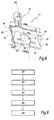
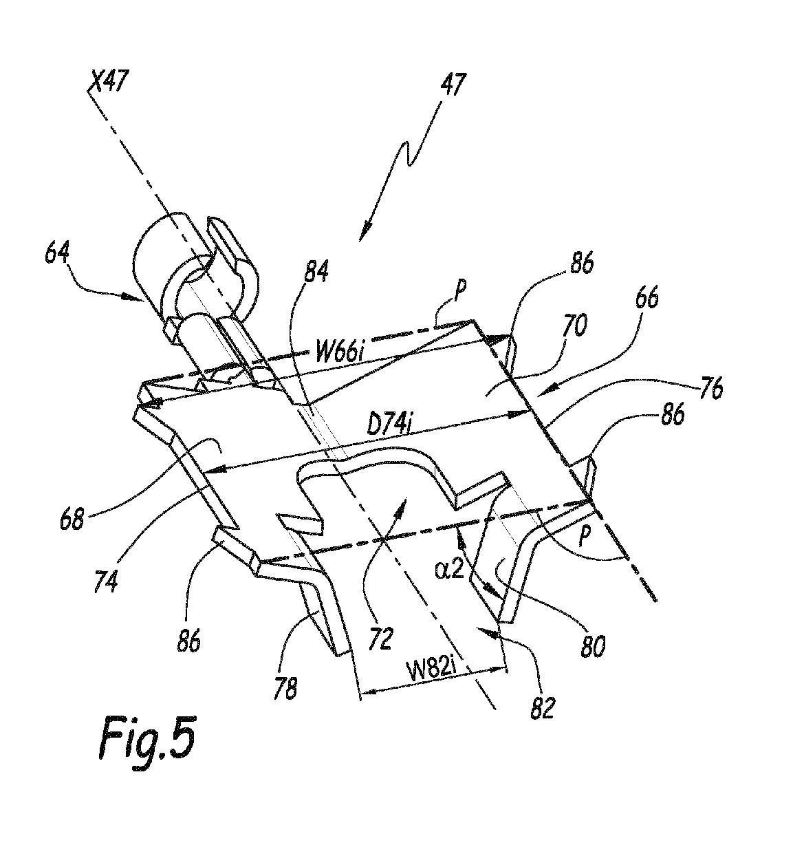
figure 5 est une vue en perspective de la cosse dans la configuration desfigures 2 à 4 . - la
figure 6 est une vue en élévation de la cosse dans la configuration desfigures 2 à5; - la
figure 7 est une vue analogue à lafigure 3 , pour laquelle la cosse est dans une configuration de connexion à la borne de connexion ; - la
figure 8 est une vue en perspective de la cosse dans la configuration de lafigure 7 ; et - la
figure 9 est un organigramme d'un procédé de connexion du câble électrique et d'un conducteur électrique de puissance à l'une des bornes de connexion du contacteur de lafigure 1 .
- the
figure 1 is a perspective view of an electrical system according to the invention comprising an electric contactor and an auxiliary device electrically coupled to the contactor via an electric cable provided with a lug; - the
figure 2 is a partial perspective view of three connection terminals of the contactor of thefigure 1 one of the connection terminals being shown exploded and the terminal being shown in an initial configuration; - the
figure 3 is an elevational view of one of the contactor connection terminals of thefigure 1 , to which is connected the electric cable provided with the pod in initial configuration; - the
figure 4 is a perspective view of the electrical cable of the system from thefigure 1 for which the pod is in its initial configuration; - the
figure 5 is a perspective view of the pod in the configuration ofFigures 2 to 4 . - the
figure 6 is an elevation view of the pod in the configuration offigures 2 at 5; - the
figure 7 is a view similar to thefigure 3 , for which the terminal is in a connection configuration at the connection terminal; - the
figure 8 is a perspective view of the pod in the configuration of thefigure 7 ; and - the
figure 9 is a flowchart of a method of connecting the electrical cable and an electrical power conductor to one of the contactor connection terminals of thefigure 1 .
Le système électrique 10 représenté sur la
Le dispositif de commutation 12 est un contacteur triphasé 12 et comprend un boîtier 16, trois premières bornes de connexion 20 d'entrée d'un courant, également appelées « premières bornes d'entrée », et trois premières bornes de connexion 22 de sortie du courant, également appelées « premières bornes de sortie ». Le contacteur 12 est connu en soi et comprend un organe de commande, non représenté, propre à interrompre la circulation du courant entre les premières bornes d'entrée 20 et de sortie 22, c'est-à-dire entre des conducteurs électriques 24 de puissance, dont un seul est représenté à la
L'appareil auxiliaire 14 comprend quatre deuxièmes bornes de connexion d'entrée 26 et quatre deuxièmes bornes de connexion de sortie 28. L'appareil auxiliaire 14 est propre à surveiller le fonctionnement du dispositif de commutation 12. Ainsi, l'appareil auxiliaire 14 est, par exemple, propre à mesurer le courant traversant les premières bornes d'entrée 20 et de sortie 22 ou à mesurer la température des premières bornes d'entrée 20 et de sortie 22. Avantageusement, l'appareil auxiliaire 14 comprend un organe de calcul, non représenté, propre à mesurer la puissance électrique et l'énergie électrique au niveau de chaque première borne de connexion d'entrée 20 et de sortie 22. L'appareil auxiliaire 14 est généralement propre à communiquer, via une liaison sans fil ou en variante filaire, avec un concentrateur de données, non représenté.The
Sur la
Chaque première borne d'entrée 20 et de sortie 22 comprend un moyen 34, visible à la
Les premières bornes d'entrée 20 et de sortie 22 comprennent chacune un logement 36 de réception d'un câble électrique 32 et d'un conducteur électrique 24.The first input and
Chaque conducteur électrique de puissance 24 est connecté soit à l'une des premières bornes d'entrée 20 soit à l'une des premières bornes de sortie 22. Plus précisément, chaque conducteur électrique de puissance 24 connecté à l'une des premières bornes d'entrée 20 est relié électriquement, via le contacteur 12, au conducteur électrique de puissance 24 connecté à la première borne de sortie 22 correspondante. Chaque conducteur électrique 24 comprend une partie terminale 38 propre à être insérée dans la première borne de connexion 20, 22 correspondante.Each
Chaque câble électrique 32 comprend un fil résistif 42, une première extrémité de connexion 44 munie d'un manchon thermorétractable 46 et d'un premier organe de connexion 47 à l'une des premières borne de connexion 20, 22, ainsi qu'une deuxième extrémité de connexion 48 munie également d'un manchon thermorétractable 50 et d'un deuxième organe 52 de connexion à l'une des deuxièmes bornes de connexion 26, 28. Ainsi, chaque câble électrique 32 s'étend entre l'une des premières bornes de connexion d'entrée 20, ou de sortie 22 et respectivement l'une des deuxièmes bornes d'entrée 26, ou de sortie 28, correspondante.Each
Chaque moyen de connexion 34 est propre à maintenir la connexion entre le conducteur électrique de puissance 24 correspondant et la première borne de connexion 20, 22 correspondante. Chaque moyen de connexion 34 comprend une vis 54 associée à un étrier 56.Each connection means 34 is adapted to maintain the connection between the
Le logement 36 est propre à recevoir le premier organe de connexion 47 et la partie terminale 38 et comprend deux parois latérales 58, 59 entre lesquelles s'étend une plage de connexion 60. Les parois latérales 58, 59 sont perpendiculaires à la plage de connexion 60.The
Le premier organe de connexion 47 correspond à une cosse 47 qui comprend une zone 64 de liaison du fil résistif 42 et une base 66. La cosse 47 est obtenue, par exemple, par pliage et découpage d'une plaque de métal. La cosse 47 s'étend suivant un axe longitudinal X47.The first connecting
La vis 54 et l'étrier 56 sont propres à exercer un effort de pression sur la cosse 47 et la partie terminale 38, afin de maintenir un contact électrique entre la plage de connexion 60, la partie terminale 38 et la cosse 47.The
La vis 54 est propre à être vissée ou dévissée afin de maintenir le conducteur électrique de puissance 24 correspondant connecté électriquement à la plage de connexion 60 correspondante ou respectivement afin de déconnecter le conducteur électrique de puissance 24 correspondant par rapport à la plage de connexion 60 correspondante.The
L'étrier 56 et la plage de connexion 60 sont distants l'un de l'autre et forme un espace E de réception de la cosse 47 et du conducteur électrique de puissance 24.The
La plage de connexion 60 comprend un trou 65 de réception de la vis 54.The
La zone de liaison 64 est de forme adaptée pour maintenir une liaison électrique entre la base 66 et le fil résistif 42.The connecting
Comme visible aux
La base 66 comprend une première partie 68 et une deuxième partie 70. La base 66 comprend également un orifice 72 de passage de la vis 54 défini entre les première 68 et deuxième 70 parties.The
Les première 68 et deuxième 70 parties comprennent respectivement un premier côté latéral 74 et un deuxième côté latéral 76, qui appartiennent à un premier plan P de la cosse 47 et définissent ce premier plan P. Les premier et deuxième côté latéraux 74, 76 s'étendent globalement suivant l'axe longitudinal X47. La distance entre les deux côtés latéraux 74, 76, lorsque la cosse est en configuration initiale, a une première valeur D74i qui est inférieure à sa valeur D74c lorsque la cosse est en configuration de connexion.The first 68 and second 70 parts respectively comprise a first
Lorsque la cosse 47 est positionnée afin d'être connectée à l'une des premières bornes de connexion 20, 22, le premier côté latéral 74 est en regard de l'une 59 des deux parois latérales, tandis que le deuxième côté latéral 76 est en regard de l'autre 58 paroi latérale.When the
Les première 68 et deuxième 70 parties comprennent également chacune une première 78 et une deuxième 80 ailettes qui délimitent entre elles, en regard de l'orifice 72, une fente 82.The first 68 and second 70 parts also each comprise a first 78 and a second 80 fins which delimit between them, opposite the
Comme représenté aux
Lorsque la cosse 47 est dans sa configuration initiale et est inséré dans l'une des premières bornes de connexion 20, 22, la base 66 correspondante a, comme présenté la
En outre, comme présenté à la
L'orifice 72 est un orifice traversant aligné avec le trou de la plage de connexion 60 lorsque la cosse 47 est connectée à la plage de connexion 60.The
Les premier 74 et deuxième 76 côtés latéraux comprennent chacun deux éléments 86 en saillie par rapport au reste de la base 66 et au côté latéral 74, 76 correspondant. Les éléments en saillie 86 sont orientés respectivement en direction des parois latérales 59, 58, lorsque la cosse 47 est connectée à la plage de connexion 60.The first 74 and second 76 lateral sides each comprise two
En configuration initiale de la cosse 47, les première 78 et deuxième 80 ailettes sont inclinées par rapport au premier plan P et la fente 82 correspond à une fente d'accès à l'orifice pour le moyen de connexion 34, plus précisément pour la vis 54. En effet, la largeur minimale de la fente 82, mesurée parallèlement au premier plan P et perpendiculairement à l'un des côtés latéraux 74, 76 a, dans la configuration initiale, une valeur W82i supérieure au diamètre D54 de la vis. En configuration initiale, un deuxième angle α2 entre chaque ailette 78, 80 et le premier plan P, mesuré du côté du plan P, est compris entre 20° et 70°, de préférence entre 40° et 60°.In the initial configuration of the
Les première 78 et deuxième 80 ailettes sont propres à être aplaties par l'étrier 56 pendant la déformation plastique de la cosse lors de son passage de la configuration initiale à la configuration de connexion. Ainsi, en configuration de connexion de la cosse 47, la largeur minimale de la fente 82, mesurée parallèlement au premier plan P et perpendiculairement à l'un des côtés latéraux 74, 76, a une valeur W82c inférieure au diamètre de la vis D54. De même, en configuration de connexion, le deuxième angle α2 est compris entre 0° et 10°.The first 78 and second 80 fins are adapted to be flattened by the
La largeur de la base 66, mesurée en configuration initiale, au niveau de chaque élément en saillie 86, parallèlement au plan P et perpendiculairement au côté latéral 74, 76 correspondant, a une valeur W66i inférieure ou égale à la distance D58 mesurée entre les deux parois latérales 58, 59, lorsque la cosse 47 est connectée à la première borne de connexion 20, 22, au niveau de l'élément en saillie 86 correspondant et perpendiculairement à la paroi latérale 58, 59 correspondante.The width of the
La largeur de la base 66, mesurée en configuration de connexion de la cosse 47, au niveau de chaque élément en saillie 86, parallèlement au plan P et perpendiculairement au côté latéral 74, 76 correspondant, a une valeur W66c supérieure à la distance D58 entre les deux parois latérales 58, 59.The width of the
Ainsi, les éléments en saillie 86 sont propres à être insérés dans les parois latérales 58, 59, en configuration de connexion de la cosse 47, puisque la valeur W66c est supérieure à la distance D58.Thus, the projecting
Les éléments en saillie 86 définissent des griffes propres à être insérées dans la paroi latérale 58, 59 correspondante lorsque la cosse 47 est déformée en configuration de connexion. Les éléments en saillie 86 sont positionnés au niveau de quatre coins formés par la base 66.The projecting
La largeur de chaque élément en saillie 86, mesurée perpendiculairement au côté latéral 74, 76 correspondant a, par exemple, une valeur W86 inférieure à 3 mm, de préférence comprise entre 0,4 mm et 1,2 mm.The width of each projecting
A la
Lors d'une première étape 100, la cosse 47 est positionnée sur la première borne de connexion 20, 22 correspondante afin d'être connectée à celle-ci. Plus précisément, les ailettes 78, 82 sont mises en contact avec la plage de connexion 60 et les éléments en saillie 86 sont orientés vers l'étrier 56. La cosse 47 est insérée au niveau de la première borne de connexion 20, 22 correspondante, de manière à ce que la vis 54 soit positionnée dans l'orifice 72. Plus précisément, la vis 54 est déjà installée et disposée dans le trou 65 et la cosse 47 est insérée dans la borne de connexion 20, 22 correspondante, afin que la vis 54 traverse la fente 82 et se retrouvent dans l'orifice 72.In a
Puis, lors d'une étape 102 suivante, la cosse 47, et plus précisément sa base 66, est aplatie. En effet, le moyen de connexion 34 vient exercer un effort de pression sur la base 66 afin de déformer plastiquement la cosse depuis sa configuration initiale vers sa configuration de connexion. En d'autres termes, une opération de vissage de la vis 54 est réalisée, afin que l'étrier 56 se déplace en direction de la plage de connexion 60 et aplatisse la base 66, c'est-à-dire les première 68 et deuxième 70 parties. Lors de cette opération de vissage, les éléments en saillie 86 viennent s'insérer dans ou griffer les parois latérales 58, 59 correspondantes et la cosse 47 est ainsi immobilisée de manière inamovible à la première borne de connexion 20, 22 correspondante. Par ailleurs, suite à l'étape 102, la cosse 47 est globalement parallèle à la plage de connexion 60 et aplatie au fond de la première borne de connexion 20, 22, c'est-à-dire contre la plage de connexion 60. De même, au cours de l'étape 102, les ailettes 78, 80 sont également aplaties de manière à réduire la largeur minimale de la fente 82 et à empêcher tout arrachement de la cosse 47 par rapport à la première borne de connexion 20, 22 correspondante.Then, in a
Généralement, précédemment ou suite à l'étape 102, le câble électrique 32, destiné à être connecté à la première borne de connexion 20, 22 correspondante via sa cosse 47, est également connecté au niveau de sa deuxième extrémité 48, via le deuxième organe de connexion 52 à la deuxième borne de connexion 26, 28 correspondante.Generally, previously or following
Ensuite, lors d'une étape 104, la vis 54 est dévissée et l'étrier 56 se déplace dans une direction opposée à la plage de connexion 60. Suite à l'étape 104 de dévissage, l'espace E est propre à recevoir le conducteur électrique de puissance 24 correspondant. Plus précisément, l'espace de réception E est formé entre d'une part la plage de connexion 60 et la cosse 47 et, d'autre part, l'étrier 56.Then, during a
Généralement, les étapes 100, 102 et 104 sont réalisées pour chaque première borne de connexion 20, 22 et suite à l'étape 104 un opérateur dispose du système électrique 10, qu'il va installer dans une installation électrique entre les conducteurs électriques de puissance 24.Generally, the
Puis, lors d'une étape 106, le conducteur électrique de puissance 24 et plus précisément, la partie terminale 38, est inséré dans l'espace de réception E, afin d'être connecté à la première borne de connexion 20, 22 correspondante.Then, during a
Ensuite, au cours d'une étape 108, une opération de vissage de la vis 54 est effectuée afin de déplacer l'étrier 56 vers la plage de connexion 60 et la cosse 47 et de maintenir la partie terminale 38 connectée à la plage de connexion 60 et coincée entre l'étrier 56 et la cosse 47.Then, during a
Le fait, qu'en configuration initiale de la cosse 47, les première 68 et deuxième 70 parties sont inclinées, permet, lors de la déformation de la cosse en configuration de connexion, que les éléments en saillie 86 viennent exercer un effort de pression contre les parois latérales 58, 59 correspondantes et s'insérer dans ces parois, sachant que les parois 58, 59 sont généralement en matériau plastique.The fact that in the initial configuration of the
De plus, l'inclinaison des première 78 et deuxième 80 ailettes permet de former la fente 82 qui est propre, en configuration initiale de la cosse 47, à laisser passer la vis 54 afin que celle-ci soit positionnée dans l'orifice 72. En effet, la vis 54 est en place dans chaque première borne de connexion 20, 22, préalablement à la connexion de la cosse 47 sur la plage de connexion 60 correspondante. De plus, le fait que les première 78 et deuxième 80 ailettes sont inclinées permet, lors de la déformation de la cosse 47 en configuration de connexion, de réduire la largeur de la fente 82 afin d'emprisonner la vis 54 dans l'orifice 72 et d'empêcher toute déconnexion de la cosse 47 de la première borne de connexion 20, 22 correspondante.In addition, the inclination of the first 78 and second 80 fins makes it possible to form the
Grâce à l'effort de pression exercé par la vis 54 et l'étrier 56 et à la déformation de la cosse 47 en configuration de connexion, la mise à plat de la cosse 47 est garantie, ce qui permet, suite à l'opération de dévissage 104, de laisser l'espace E entre la plage de connexion 60 et l'étrier 56. Le volume de l'espace E est optimisé, ce qui permet de faciliter l'accès à la première borne de connexion 20, 22 correspondante, suite à la connexion de la cosse 47. Ainsi l'espace E permet de faciliter la connexion du conducteur électrique de puissance 24, c'est à dire de sa partie terminale 38, à la première borne de connexion correspondante 20, 22. Puisque la connexion du conducteur électrique 24 est facilité et que la cosse est mise à plat contre la plage de connexion 60 correspondante, la qualité du contact électrique entre la plage de connexion60, la cosse 47 et le conducteur électrique de puissance 24 est garantie et améliorée.Thanks to the pressure force exerted by the
De plus, les première 78 et deuxième 80 ailettes, ainsi que les éléments en saillie 86 garantissent un caractère inamovible à la cosse 47 par rapport à la première borne de connexion 20, 22 correspondante, afin de garantir la connexion entre l'appareil auxiliaire 14 et le contacteur 12. Les fils résistifs 42 sont indémontables et ainsi la connexion entre le dispositif de commutation 12 et l'appareil auxiliaire 14 est garantie indémontable par l'opérateur.In addition, the first 78 and second 80 fins, as well as the projecting
Le système électrique 10 présenté à la
En variante, la cosse 47 permet la connexion du câble électrique 32 ou d'un autre type de câble électrique à tout type de borne de connexion comprenant une plage de connexion et des parois latérales, similaires à la plage de connexion 60 et aux parois latérales 58, 59.Alternatively, the
Selon une autre variante, le dispositif de commutation 12 est un contacteur monophasé comprenant une seule ou deux premières bornes d'entrée et une seule ou deux premières bornes de sortie.According to another variant, the switching
Selon une autre variante, le dispositif de commutation 12 est, par exemple, un disjoncteur.According to another variant, the switching
Selon une autre variante, une seul des première 68 et deuxième 70 parties comprend une ailette formant avec le reste de la cosse la fente 82.According to another variant, only one of the first 68 and second 70 parts comprises a fin forming with the rest of the
Selon une autre variante, chaque côté latéral 74, 76 comprend un unique élément en saillie 86.According to another variant, each
Selon une autre variante, uniquement un seul des côtés latéraux 74, 76 comprend un ou plusieurs éléments en saillie 86.According to another variant, only one of the lateral sides 74, 76 comprises one or more projecting
Selon une autre variante, des éléments en saillie sont disposés sur toute la longueur des côtés latéraux 74, 76 et la largeur des éléments en saillie, mesurée perpendiculairement aux parois latérales 58, 59, varie de manière croissante ou décroissante le long des côtés latéraux 74, 76.According to another variant, projecting elements are arranged along the entire length of the lateral sides 74, 76 and the width of the protruding elements, measured perpendicularly to the
Selon une autre variante, lorsque la cosse 47 est inséré dans l'une des premières bornes de connexion 20, 22, précédemment à sa connexion à l'une des premières bornes de connexion 20, 22, la base 66 correspondante à son arête 84 orientée vers l'étrier 56 et ses côtés latéraux 74, 76 en contact avec la plage de connexion 60.According to another variant, when the
Le moyen de connexion 34 peut être de tout type tant qu'il est propre à appliquer un effort de pression sur la cosse 47, c'est-à-dire sur la base 66, afin de déformer la cosse 47 depuis sa configuration initiale vers sa configuration de connexion.The connection means 34 may be of any type as long as it is capable of applying a pressure force on the
Les différentes variantes décrites ci-dessus peuvent être combinées entre elles totalement ou partiellement, pour donner lieu à d'autres modes de réalisation de l'invention.The various variants described above can be combined together wholly or partially, to give rise to other embodiments of the invention.
Claims (11)
Applications Claiming Priority (1)
| Application Number | Priority Date | Filing Date | Title |
|---|---|---|---|
| FR1362631A FR3015132B1 (en) | 2013-12-13 | 2013-12-13 | ELECTRICAL CONNECTING TERMINAL WITH CONNECTION TERMINAL, ASSOCIATED ELECTRICAL SYSTEM AND METHOD FOR CONNECTING SUCH TERMINAL TO CONNECTION TERMINAL |
Publications (2)
| Publication Number | Publication Date |
|---|---|
| EP2884591A1 true EP2884591A1 (en) | 2015-06-17 |
| EP2884591B1 EP2884591B1 (en) | 2020-09-23 |
Family
ID=50489229
Family Applications (1)
| Application Number | Title | Priority Date | Filing Date |
|---|---|---|---|
| EP14197686.0A Active EP2884591B1 (en) | 2013-12-13 | 2014-12-12 | Lug for electrical connection to a connection terminal, associated electrical system and method for connecting such a lug to a connection terminal |
Country Status (3)
| Country | Link |
|---|---|
| EP (1) | EP2884591B1 (en) |
| CN (1) | CN204793320U (en) |
| FR (1) | FR3015132B1 (en) |
Citations (2)
| Publication number | Priority date | Publication date | Assignee | Title |
|---|---|---|---|---|
| US3344394A (en) * | 1966-05-16 | 1967-09-26 | Zinsco Electrical Products | Limited engagement lug assembly |
| WO2007143805A2 (en) | 2006-06-14 | 2007-12-21 | Tyco Electronics Brasil Ltda | Closed idc terminal |
Family Cites Families (2)
| Publication number | Priority date | Publication date | Assignee | Title |
|---|---|---|---|---|
| US6242993B1 (en) * | 1995-03-13 | 2001-06-05 | Square D Company | Apparatus for use in arcing fault detection systems |
| DE102006049810B4 (en) * | 2006-10-17 | 2008-07-10 | Siemens Ag | Circuit breaker, in particular molded case circuit breaker, and auxiliary conductor connection for a circuit breaker |
-
2013
- 2013-12-13 FR FR1362631A patent/FR3015132B1/en not_active Expired - Fee Related
-
2014
- 2014-12-12 EP EP14197686.0A patent/EP2884591B1/en active Active
- 2014-12-15 CN CN201420794850.9U patent/CN204793320U/en not_active Expired - Lifetime
Patent Citations (2)
| Publication number | Priority date | Publication date | Assignee | Title |
|---|---|---|---|---|
| US3344394A (en) * | 1966-05-16 | 1967-09-26 | Zinsco Electrical Products | Limited engagement lug assembly |
| WO2007143805A2 (en) | 2006-06-14 | 2007-12-21 | Tyco Electronics Brasil Ltda | Closed idc terminal |
Also Published As
| Publication number | Publication date |
|---|---|
| FR3015132B1 (en) | 2017-03-10 |
| EP2884591B1 (en) | 2020-09-23 |
| CN204793320U (en) | 2015-11-18 |
| FR3015132A1 (en) | 2015-06-19 |
Similar Documents
| Publication | Publication Date | Title |
|---|---|---|
| EP2521224B1 (en) | Quick connection device for electrical appliance | |
| FR3082669A1 (en) | METAL CLIP FOR ELECTRICAL CONNECTION OF A CONDUCTING WIRE TO A METAL ELEMENT | |
| EP3314682B1 (en) | Electric energy storage module | |
| FR2742918A1 (en) | DEVICE FOR CONNECTING AN OUTDOOR CONDUCTOR SUCH AS A CABLE TO A CONTACT RANGE OF AN ELECTRICAL APPARATUS | |
| EP2884591B1 (en) | Lug for electrical connection to a connection terminal, associated electrical system and method for connecting such a lug to a connection terminal | |
| FR3020467A1 (en) | DEVICE FOR MEASURING AT LEAST ONE ELECTRICAL SIZE OF A CURRENT FOR CIRCULATING IN AN ELECTRICAL APPARATUS, AND ASSEMBLY COMPRISING SUCH A DEVICE | |
| WO2018011481A1 (en) | Device for measuring a current, the device being fastened vertically onto a battery terminal | |
| FR2766297A1 (en) | ELECTRICAL APPARATUS CARRYING A FIXED CONTACT SUPPORT AND A TERMINAL | |
| FR2963488A1 (en) | Multipolar electric connection nozzle for connecting e.g. electric copper wire of electrical cable on electric terminal of electric meter in electrical box, has housing whose electrical contact member is connected electrically to wire | |
| FR2772979A1 (en) | ELECTRICAL CONNECTION DEVICE OF A DIFFERENTIAL BLOCK ON A CIRCUIT BREAKER OR SIMILAR AND DIFFERENTIAL BLOCK EQUIPPED WITH SUCH A DEVICE | |
| EP2990811B1 (en) | Device for contactless measurement of an electrical voltage in a cable of a medium- or high-voltage electric network | |
| FR3010838A1 (en) | TERMINAL WITH DOUBLE ELECTRICAL CONNECTION SYSTEM, IN PARTICULAR FOR A LOW VOLTAGE ELECTRICAL PROTECTION APPARATUS, AND APPARATUS COMPRISING SUCH A TERMINAL | |
| EP4343805A1 (en) | Protection module for a power supply input of an electrical switchgear of the nh fuse-disconnector type | |
| EP2190275A1 (en) | Housing for an electronic module for controlling a machine | |
| EP1825278B1 (en) | Electric connection device for a polyphase electric meter | |
| BE1030628B1 (en) | A power cut protection device for electric vehicles | |
| FR3127637A1 (en) | Protection device for prismatic electrochemical accumulator | |
| EP3599629B1 (en) | Shut-off device for a vehicle and associated vehicle | |
| FR3101193A1 (en) | Fuse electrical switch-off device | |
| EP3667688A1 (en) | Electrical assembly comprising a capacitive element | |
| EP3561968A1 (en) | Electrical connection system for voltage transformer | |
| EP3435398B1 (en) | Differential electrical protection apparatus | |
| FR3156255A1 (en) | Electronic cut-off protection device | |
| EP4343799A1 (en) | Current transformation module for an electrical switchgear of the nh fuse-disconnector type | |
| BE1010987A3 (en) | Automatic protection device against voltage surges, spring type with earthing function |
Legal Events
| Date | Code | Title | Description |
|---|---|---|---|
| PUAI | Public reference made under article 153(3) epc to a published international application that has entered the european phase |
Free format text: ORIGINAL CODE: 0009012 |
|
| 17P | Request for examination filed |
Effective date: 20141212 |
|
| AK | Designated contracting states |
Kind code of ref document: A1 Designated state(s): AL AT BE BG CH CY CZ DE DK EE ES FI FR GB GR HR HU IE IS IT LI LT LU LV MC MK MT NL NO PL PT RO RS SE SI SK SM TR |
|
| AX | Request for extension of the european patent |
Extension state: BA ME |
|
| R17P | Request for examination filed (corrected) |
Effective date: 20150803 |
|
| RBV | Designated contracting states (corrected) |
Designated state(s): AL AT BE BG CH CY CZ DE DK EE ES FI FR GB GR HR HU IE IS IT LI LT LU LV MC MK MT NL NO PL PT RO RS SE SI SK SM TR |
|
| STAA | Information on the status of an ep patent application or granted ep patent |
Free format text: STATUS: EXAMINATION IS IN PROGRESS |
|
| 17Q | First examination report despatched |
Effective date: 20170904 |
|
| GRAP | Despatch of communication of intention to grant a patent |
Free format text: ORIGINAL CODE: EPIDOSNIGR1 |
|
| STAA | Information on the status of an ep patent application or granted ep patent |
Free format text: STATUS: GRANT OF PATENT IS INTENDED |
|
| INTG | Intention to grant announced |
Effective date: 20200528 |
|
| GRAS | Grant fee paid |
Free format text: ORIGINAL CODE: EPIDOSNIGR3 |
|
| GRAA | (expected) grant |
Free format text: ORIGINAL CODE: 0009210 |
|
| STAA | Information on the status of an ep patent application or granted ep patent |
Free format text: STATUS: THE PATENT HAS BEEN GRANTED |
|
| AK | Designated contracting states |
Kind code of ref document: B1 Designated state(s): AL AT BE BG CH CY CZ DE DK EE ES FI FR GB GR HR HU IE IS IT LI LT LU LV MC MK MT NL NO PL PT RO RS SE SI SK SM TR |
|
| REG | Reference to a national code |
Ref country code: GB Ref legal event code: FG4D Free format text: NOT ENGLISH |
|
| REG | Reference to a national code |
Ref country code: CH Ref legal event code: EP |
|
| REG | Reference to a national code |
Ref country code: DE Ref legal event code: R096 Ref document number: 602014070432 Country of ref document: DE |
|
| REG | Reference to a national code |
Ref country code: IE Ref legal event code: FG4D Free format text: LANGUAGE OF EP DOCUMENT: FRENCH |
|
| REG | Reference to a national code |
Ref country code: AT Ref legal event code: REF Ref document number: 1317326 Country of ref document: AT Kind code of ref document: T Effective date: 20201015 |
|
| PG25 | Lapsed in a contracting state [announced via postgrant information from national office to epo] |
Ref country code: GR Free format text: LAPSE BECAUSE OF FAILURE TO SUBMIT A TRANSLATION OF THE DESCRIPTION OR TO PAY THE FEE WITHIN THE PRESCRIBED TIME-LIMIT Effective date: 20201224 Ref country code: BG Free format text: LAPSE BECAUSE OF FAILURE TO SUBMIT A TRANSLATION OF THE DESCRIPTION OR TO PAY THE FEE WITHIN THE PRESCRIBED TIME-LIMIT Effective date: 20201223 Ref country code: NO Free format text: LAPSE BECAUSE OF FAILURE TO SUBMIT A TRANSLATION OF THE DESCRIPTION OR TO PAY THE FEE WITHIN THE PRESCRIBED TIME-LIMIT Effective date: 20201223 Ref country code: SE Free format text: LAPSE BECAUSE OF FAILURE TO SUBMIT A TRANSLATION OF THE DESCRIPTION OR TO PAY THE FEE WITHIN THE PRESCRIBED TIME-LIMIT Effective date: 20200923 Ref country code: HR Free format text: LAPSE BECAUSE OF FAILURE TO SUBMIT A TRANSLATION OF THE DESCRIPTION OR TO PAY THE FEE WITHIN THE PRESCRIBED TIME-LIMIT Effective date: 20200923 Ref country code: FI Free format text: LAPSE BECAUSE OF FAILURE TO SUBMIT A TRANSLATION OF THE DESCRIPTION OR TO PAY THE FEE WITHIN THE PRESCRIBED TIME-LIMIT Effective date: 20200923 |
|
| REG | Reference to a national code |
Ref country code: AT Ref legal event code: MK05 Ref document number: 1317326 Country of ref document: AT Kind code of ref document: T Effective date: 20200923 |
|
| PG25 | Lapsed in a contracting state [announced via postgrant information from national office to epo] |
Ref country code: LV Free format text: LAPSE BECAUSE OF FAILURE TO SUBMIT A TRANSLATION OF THE DESCRIPTION OR TO PAY THE FEE WITHIN THE PRESCRIBED TIME-LIMIT Effective date: 20200923 Ref country code: RS Free format text: LAPSE BECAUSE OF FAILURE TO SUBMIT A TRANSLATION OF THE DESCRIPTION OR TO PAY THE FEE WITHIN THE PRESCRIBED TIME-LIMIT Effective date: 20200923 |
|
| REG | Reference to a national code |
Ref country code: NL Ref legal event code: MP Effective date: 20200923 |
|
| REG | Reference to a national code |
Ref country code: LT Ref legal event code: MG4D |
|
| PG25 | Lapsed in a contracting state [announced via postgrant information from national office to epo] |
Ref country code: SM Free format text: LAPSE BECAUSE OF FAILURE TO SUBMIT A TRANSLATION OF THE DESCRIPTION OR TO PAY THE FEE WITHIN THE PRESCRIBED TIME-LIMIT Effective date: 20200923 Ref country code: RO Free format text: LAPSE BECAUSE OF FAILURE TO SUBMIT A TRANSLATION OF THE DESCRIPTION OR TO PAY THE FEE WITHIN THE PRESCRIBED TIME-LIMIT Effective date: 20200923 Ref country code: LT Free format text: LAPSE BECAUSE OF FAILURE TO SUBMIT A TRANSLATION OF THE DESCRIPTION OR TO PAY THE FEE WITHIN THE PRESCRIBED TIME-LIMIT Effective date: 20200923 Ref country code: NL Free format text: LAPSE BECAUSE OF FAILURE TO SUBMIT A TRANSLATION OF THE DESCRIPTION OR TO PAY THE FEE WITHIN THE PRESCRIBED TIME-LIMIT Effective date: 20200923 Ref country code: PT Free format text: LAPSE BECAUSE OF FAILURE TO SUBMIT A TRANSLATION OF THE DESCRIPTION OR TO PAY THE FEE WITHIN THE PRESCRIBED TIME-LIMIT Effective date: 20210125 Ref country code: CZ Free format text: LAPSE BECAUSE OF FAILURE TO SUBMIT A TRANSLATION OF THE DESCRIPTION OR TO PAY THE FEE WITHIN THE PRESCRIBED TIME-LIMIT Effective date: 20200923 Ref country code: EE Free format text: LAPSE BECAUSE OF FAILURE TO SUBMIT A TRANSLATION OF THE DESCRIPTION OR TO PAY THE FEE WITHIN THE PRESCRIBED TIME-LIMIT Effective date: 20200923 |
|
| PG25 | Lapsed in a contracting state [announced via postgrant information from national office to epo] |
Ref country code: IS Free format text: LAPSE BECAUSE OF FAILURE TO SUBMIT A TRANSLATION OF THE DESCRIPTION OR TO PAY THE FEE WITHIN THE PRESCRIBED TIME-LIMIT Effective date: 20210123 Ref country code: PL Free format text: LAPSE BECAUSE OF FAILURE TO SUBMIT A TRANSLATION OF THE DESCRIPTION OR TO PAY THE FEE WITHIN THE PRESCRIBED TIME-LIMIT Effective date: 20200923 Ref country code: ES Free format text: LAPSE BECAUSE OF FAILURE TO SUBMIT A TRANSLATION OF THE DESCRIPTION OR TO PAY THE FEE WITHIN THE PRESCRIBED TIME-LIMIT Effective date: 20200923 Ref country code: AT Free format text: LAPSE BECAUSE OF FAILURE TO SUBMIT A TRANSLATION OF THE DESCRIPTION OR TO PAY THE FEE WITHIN THE PRESCRIBED TIME-LIMIT Effective date: 20200923 Ref country code: AL Free format text: LAPSE BECAUSE OF FAILURE TO SUBMIT A TRANSLATION OF THE DESCRIPTION OR TO PAY THE FEE WITHIN THE PRESCRIBED TIME-LIMIT Effective date: 20200923 |
|
| REG | Reference to a national code |
Ref country code: DE Ref legal event code: R097 Ref document number: 602014070432 Country of ref document: DE |
|
| PG25 | Lapsed in a contracting state [announced via postgrant information from national office to epo] |
Ref country code: SK Free format text: LAPSE BECAUSE OF FAILURE TO SUBMIT A TRANSLATION OF THE DESCRIPTION OR TO PAY THE FEE WITHIN THE PRESCRIBED TIME-LIMIT Effective date: 20200923 |
|
| PLBE | No opposition filed within time limit |
Free format text: ORIGINAL CODE: 0009261 |
|
| REG | Reference to a national code |
Ref country code: CH Ref legal event code: PL |
|
| STAA | Information on the status of an ep patent application or granted ep patent |
Free format text: STATUS: NO OPPOSITION FILED WITHIN TIME LIMIT |
|
| GBPC | Gb: european patent ceased through non-payment of renewal fee |
Effective date: 20201223 |
|
| PG25 | Lapsed in a contracting state [announced via postgrant information from national office to epo] |
Ref country code: SI Free format text: LAPSE BECAUSE OF FAILURE TO SUBMIT A TRANSLATION OF THE DESCRIPTION OR TO PAY THE FEE WITHIN THE PRESCRIBED TIME-LIMIT Effective date: 20200923 Ref country code: DK Free format text: LAPSE BECAUSE OF FAILURE TO SUBMIT A TRANSLATION OF THE DESCRIPTION OR TO PAY THE FEE WITHIN THE PRESCRIBED TIME-LIMIT Effective date: 20200923 Ref country code: MC Free format text: LAPSE BECAUSE OF FAILURE TO SUBMIT A TRANSLATION OF THE DESCRIPTION OR TO PAY THE FEE WITHIN THE PRESCRIBED TIME-LIMIT Effective date: 20200923 |
|
| 26N | No opposition filed |
Effective date: 20210624 |
|
| REG | Reference to a national code |
Ref country code: BE Ref legal event code: MM Effective date: 20201231 |
|
| PG25 | Lapsed in a contracting state [announced via postgrant information from national office to epo] |
Ref country code: IT Free format text: LAPSE BECAUSE OF FAILURE TO SUBMIT A TRANSLATION OF THE DESCRIPTION OR TO PAY THE FEE WITHIN THE PRESCRIBED TIME-LIMIT Effective date: 20200923 Ref country code: IE Free format text: LAPSE BECAUSE OF NON-PAYMENT OF DUE FEES Effective date: 20201212 Ref country code: LU Free format text: LAPSE BECAUSE OF NON-PAYMENT OF DUE FEES Effective date: 20201212 |
|
| PG25 | Lapsed in a contracting state [announced via postgrant information from national office to epo] |
Ref country code: GB Free format text: LAPSE BECAUSE OF NON-PAYMENT OF DUE FEES Effective date: 20201223 Ref country code: CH Free format text: LAPSE BECAUSE OF NON-PAYMENT OF DUE FEES Effective date: 20201231 Ref country code: LI Free format text: LAPSE BECAUSE OF NON-PAYMENT OF DUE FEES Effective date: 20201231 |
|
| PG25 | Lapsed in a contracting state [announced via postgrant information from national office to epo] |
Ref country code: IS Free format text: LAPSE BECAUSE OF FAILURE TO SUBMIT A TRANSLATION OF THE DESCRIPTION OR TO PAY THE FEE WITHIN THE PRESCRIBED TIME-LIMIT Effective date: 20210123 Ref country code: MT Free format text: LAPSE BECAUSE OF FAILURE TO SUBMIT A TRANSLATION OF THE DESCRIPTION OR TO PAY THE FEE WITHIN THE PRESCRIBED TIME-LIMIT Effective date: 20200923 Ref country code: CY Free format text: LAPSE BECAUSE OF FAILURE TO SUBMIT A TRANSLATION OF THE DESCRIPTION OR TO PAY THE FEE WITHIN THE PRESCRIBED TIME-LIMIT Effective date: 20200923 |
|
| PG25 | Lapsed in a contracting state [announced via postgrant information from national office to epo] |
Ref country code: MK Free format text: LAPSE BECAUSE OF FAILURE TO SUBMIT A TRANSLATION OF THE DESCRIPTION OR TO PAY THE FEE WITHIN THE PRESCRIBED TIME-LIMIT Effective date: 20200923 |
|
| PG25 | Lapsed in a contracting state [announced via postgrant information from national office to epo] |
Ref country code: BE Free format text: LAPSE BECAUSE OF NON-PAYMENT OF DUE FEES Effective date: 20201231 |
|
| PGFP | Annual fee paid to national office [announced via postgrant information from national office to epo] |
Ref country code: TR Payment date: 20241202 Year of fee payment: 11 |
|
| PGFP | Annual fee paid to national office [announced via postgrant information from national office to epo] |
Ref country code: DE Payment date: 20241227 Year of fee payment: 11 |
|
| PGFP | Annual fee paid to national office [announced via postgrant information from national office to epo] |
Ref country code: FR Payment date: 20251230 Year of fee payment: 12 |