EP2884563B1 - Electrode lead and secondary battery having same - Google Patents
Electrode lead and secondary battery having same Download PDFInfo
- Publication number
- EP2884563B1 EP2884563B1 EP13847024.0A EP13847024A EP2884563B1 EP 2884563 B1 EP2884563 B1 EP 2884563B1 EP 13847024 A EP13847024 A EP 13847024A EP 2884563 B1 EP2884563 B1 EP 2884563B1
- Authority
- EP
- European Patent Office
- Prior art keywords
- lead
- pouch
- secondary battery
- inner lead
- flow path
- Prior art date
- Legal status (The legal status is an assumption and is not a legal conclusion. Google has not performed a legal analysis and makes no representation as to the accuracy of the status listed.)
- Active
Links
- 238000007789 sealing Methods 0.000 claims description 53
- 239000004020 conductor Substances 0.000 claims description 30
- 239000012811 non-conductive material Substances 0.000 claims description 12
- 229910052782 aluminium Inorganic materials 0.000 claims description 7
- XAGFODPZIPBFFR-UHFFFAOYSA-N aluminium Chemical compound [Al] XAGFODPZIPBFFR-UHFFFAOYSA-N 0.000 claims description 7
- 239000012790 adhesive layer Substances 0.000 claims description 6
- 238000012856 packing Methods 0.000 claims description 6
- XEEYBQQBJWHFJM-UHFFFAOYSA-N Iron Chemical compound [Fe] XEEYBQQBJWHFJM-UHFFFAOYSA-N 0.000 claims description 4
- PXHVJJICTQNCMI-UHFFFAOYSA-N Nickel Chemical compound [Ni] PXHVJJICTQNCMI-UHFFFAOYSA-N 0.000 claims description 4
- VYZAMTAEIAYCRO-UHFFFAOYSA-N Chromium Chemical compound [Cr] VYZAMTAEIAYCRO-UHFFFAOYSA-N 0.000 claims description 2
- RYGMFSIKBFXOCR-UHFFFAOYSA-N Copper Chemical compound [Cu] RYGMFSIKBFXOCR-UHFFFAOYSA-N 0.000 claims description 2
- BQCADISMDOOEFD-UHFFFAOYSA-N Silver Chemical compound [Ag] BQCADISMDOOEFD-UHFFFAOYSA-N 0.000 claims description 2
- 229910045601 alloy Inorganic materials 0.000 claims description 2
- 239000000956 alloy Substances 0.000 claims description 2
- 229910052802 copper Inorganic materials 0.000 claims description 2
- 239000010949 copper Substances 0.000 claims description 2
- PCHJSUWPFVWCPO-UHFFFAOYSA-N gold Chemical compound [Au] PCHJSUWPFVWCPO-UHFFFAOYSA-N 0.000 claims description 2
- 229910052737 gold Inorganic materials 0.000 claims description 2
- 239000010931 gold Substances 0.000 claims description 2
- 229910052742 iron Inorganic materials 0.000 claims description 2
- 239000010410 layer Substances 0.000 claims description 2
- 229910052759 nickel Inorganic materials 0.000 claims description 2
- 229920000642 polymer Polymers 0.000 claims description 2
- 229910052709 silver Inorganic materials 0.000 claims description 2
- 239000004332 silver Substances 0.000 claims description 2
- 239000010409 thin film Substances 0.000 claims description 2
- 238000010276 construction Methods 0.000 description 32
- 238000004880 explosion Methods 0.000 description 8
- 239000008151 electrolyte solution Substances 0.000 description 7
- WHXSMMKQMYFTQS-UHFFFAOYSA-N Lithium Chemical compound [Li] WHXSMMKQMYFTQS-UHFFFAOYSA-N 0.000 description 5
- 229910052744 lithium Inorganic materials 0.000 description 5
- 238000010586 diagram Methods 0.000 description 4
- 239000011149 active material Substances 0.000 description 3
- 239000011248 coating agent Substances 0.000 description 3
- 238000000576 coating method Methods 0.000 description 3
- 238000003780 insertion Methods 0.000 description 3
- 230000037431 insertion Effects 0.000 description 3
- 239000000463 material Substances 0.000 description 3
- 229910052751 metal Inorganic materials 0.000 description 3
- 239000002184 metal Substances 0.000 description 3
- 238000000034 method Methods 0.000 description 3
- 239000002002 slurry Substances 0.000 description 3
- 230000002159 abnormal effect Effects 0.000 description 2
- 239000006183 anode active material Substances 0.000 description 2
- 239000006182 cathode active material Substances 0.000 description 2
- 238000007599 discharging Methods 0.000 description 2
- 238000012986 modification Methods 0.000 description 2
- 230000004048 modification Effects 0.000 description 2
- 230000001151 other effect Effects 0.000 description 2
- 230000035515 penetration Effects 0.000 description 2
- 238000000926 separation method Methods 0.000 description 2
- 239000002390 adhesive tape Substances 0.000 description 1
- 239000011230 binding agent Substances 0.000 description 1
- OJIJEKBXJYRIBZ-UHFFFAOYSA-N cadmium nickel Chemical compound [Ni].[Cd] OJIJEKBXJYRIBZ-UHFFFAOYSA-N 0.000 description 1
- 239000003575 carbonaceous material Substances 0.000 description 1
- 230000007797 corrosion Effects 0.000 description 1
- 238000005260 corrosion Methods 0.000 description 1
- 238000000354 decomposition reaction Methods 0.000 description 1
- 230000000694 effects Effects 0.000 description 1
- 239000003792 electrolyte Substances 0.000 description 1
- 238000005516 engineering process Methods 0.000 description 1
- 230000002349 favourable effect Effects 0.000 description 1
- 238000002309 gasification Methods 0.000 description 1
- 229910052987 metal hydride Inorganic materials 0.000 description 1
- 239000004014 plasticizer Substances 0.000 description 1
- 230000002265 prevention Effects 0.000 description 1
- 239000000565 sealant Substances 0.000 description 1
- 239000000243 solution Substances 0.000 description 1
- 239000002904 solvent Substances 0.000 description 1
- 238000003756 stirring Methods 0.000 description 1
- 230000008961 swelling Effects 0.000 description 1
- 238000003466 welding Methods 0.000 description 1
Images


Classifications
-
- H—ELECTRICITY
- H01—ELECTRIC ELEMENTS
- H01M—PROCESSES OR MEANS, e.g. BATTERIES, FOR THE DIRECT CONVERSION OF CHEMICAL ENERGY INTO ELECTRICAL ENERGY
- H01M50/00—Constructional details or processes of manufacture of the non-active parts of electrochemical cells other than fuel cells, e.g. hybrid cells
- H01M50/50—Current conducting connections for cells or batteries
- H01M50/531—Electrode connections inside a battery casing
-
- H—ELECTRICITY
- H01—ELECTRIC ELEMENTS
- H01M—PROCESSES OR MEANS, e.g. BATTERIES, FOR THE DIRECT CONVERSION OF CHEMICAL ENERGY INTO ELECTRICAL ENERGY
- H01M10/00—Secondary cells; Manufacture thereof
- H01M10/02—Details
-
- H—ELECTRICITY
- H01—ELECTRIC ELEMENTS
- H01M—PROCESSES OR MEANS, e.g. BATTERIES, FOR THE DIRECT CONVERSION OF CHEMICAL ENERGY INTO ELECTRICAL ENERGY
- H01M10/00—Secondary cells; Manufacture thereof
- H01M10/42—Methods or arrangements for servicing or maintenance of secondary cells or secondary half-cells
- H01M10/4235—Safety or regulating additives or arrangements in electrodes, separators or electrolyte
-
- H—ELECTRICITY
- H01—ELECTRIC ELEMENTS
- H01M—PROCESSES OR MEANS, e.g. BATTERIES, FOR THE DIRECT CONVERSION OF CHEMICAL ENERGY INTO ELECTRICAL ENERGY
- H01M50/00—Constructional details or processes of manufacture of the non-active parts of electrochemical cells other than fuel cells, e.g. hybrid cells
- H01M50/10—Primary casings, jackets or wrappings of a single cell or a single battery
- H01M50/172—Arrangements of electric connectors penetrating the casing
- H01M50/174—Arrangements of electric connectors penetrating the casing adapted for the shape of the cells
- H01M50/176—Arrangements of electric connectors penetrating the casing adapted for the shape of the cells for prismatic or rectangular cells
-
- H—ELECTRICITY
- H01—ELECTRIC ELEMENTS
- H01M—PROCESSES OR MEANS, e.g. BATTERIES, FOR THE DIRECT CONVERSION OF CHEMICAL ENERGY INTO ELECTRICAL ENERGY
- H01M50/00—Constructional details or processes of manufacture of the non-active parts of electrochemical cells other than fuel cells, e.g. hybrid cells
- H01M50/30—Arrangements for facilitating escape of gases
- H01M50/342—Non-re-sealable arrangements
-
- H—ELECTRICITY
- H01—ELECTRIC ELEMENTS
- H01M—PROCESSES OR MEANS, e.g. BATTERIES, FOR THE DIRECT CONVERSION OF CHEMICAL ENERGY INTO ELECTRICAL ENERGY
- H01M50/00—Constructional details or processes of manufacture of the non-active parts of electrochemical cells other than fuel cells, e.g. hybrid cells
- H01M50/50—Current conducting connections for cells or batteries
- H01M50/543—Terminals
- H01M50/547—Terminals characterised by the disposition of the terminals on the cells
- H01M50/55—Terminals characterised by the disposition of the terminals on the cells on the same side of the cell
-
- H—ELECTRICITY
- H01—ELECTRIC ELEMENTS
- H01M—PROCESSES OR MEANS, e.g. BATTERIES, FOR THE DIRECT CONVERSION OF CHEMICAL ENERGY INTO ELECTRICAL ENERGY
- H01M50/00—Constructional details or processes of manufacture of the non-active parts of electrochemical cells other than fuel cells, e.g. hybrid cells
- H01M50/50—Current conducting connections for cells or batteries
- H01M50/543—Terminals
- H01M50/552—Terminals characterised by their shape
- H01M50/553—Terminals adapted for prismatic, pouch or rectangular cells
-
- H—ELECTRICITY
- H01—ELECTRIC ELEMENTS
- H01M—PROCESSES OR MEANS, e.g. BATTERIES, FOR THE DIRECT CONVERSION OF CHEMICAL ENERGY INTO ELECTRICAL ENERGY
- H01M50/00—Constructional details or processes of manufacture of the non-active parts of electrochemical cells other than fuel cells, e.g. hybrid cells
- H01M50/50—Current conducting connections for cells or batteries
- H01M50/543—Terminals
- H01M50/562—Terminals characterised by the material
-
- H—ELECTRICITY
- H01—ELECTRIC ELEMENTS
- H01M—PROCESSES OR MEANS, e.g. BATTERIES, FOR THE DIRECT CONVERSION OF CHEMICAL ENERGY INTO ELECTRICAL ENERGY
- H01M50/00—Constructional details or processes of manufacture of the non-active parts of electrochemical cells other than fuel cells, e.g. hybrid cells
- H01M50/50—Current conducting connections for cells or batteries
- H01M50/572—Means for preventing undesired use or discharge
- H01M50/574—Devices or arrangements for the interruption of current
- H01M50/578—Devices or arrangements for the interruption of current in response to pressure
-
- H—ELECTRICITY
- H01—ELECTRIC ELEMENTS
- H01M—PROCESSES OR MEANS, e.g. BATTERIES, FOR THE DIRECT CONVERSION OF CHEMICAL ENERGY INTO ELECTRICAL ENERGY
- H01M2200/00—Safety devices for primary or secondary batteries
- H01M2200/20—Pressure-sensitive devices
-
- H—ELECTRICITY
- H01—ELECTRIC ELEMENTS
- H01M—PROCESSES OR MEANS, e.g. BATTERIES, FOR THE DIRECT CONVERSION OF CHEMICAL ENERGY INTO ELECTRICAL ENERGY
- H01M50/00—Constructional details or processes of manufacture of the non-active parts of electrochemical cells other than fuel cells, e.g. hybrid cells
- H01M50/30—Arrangements for facilitating escape of gases
-
- Y—GENERAL TAGGING OF NEW TECHNOLOGICAL DEVELOPMENTS; GENERAL TAGGING OF CROSS-SECTIONAL TECHNOLOGIES SPANNING OVER SEVERAL SECTIONS OF THE IPC; TECHNICAL SUBJECTS COVERED BY FORMER USPC CROSS-REFERENCE ART COLLECTIONS [XRACs] AND DIGESTS
- Y02—TECHNOLOGIES OR APPLICATIONS FOR MITIGATION OR ADAPTATION AGAINST CLIMATE CHANGE
- Y02E—REDUCTION OF GREENHOUSE GAS [GHG] EMISSIONS, RELATED TO ENERGY GENERATION, TRANSMISSION OR DISTRIBUTION
- Y02E60/00—Enabling technologies; Technologies with a potential or indirect contribution to GHG emissions mitigation
- Y02E60/10—Energy storage using batteries
Definitions
- the present disclosure relates to a secondary battery technology, and more particularly, to an electrode lead with enhanced structure to improve safety in the event that the internal pressure of a secondary battery increases, and a secondary battery and a battery pack including the same.
- a secondary battery is rechargeable, and is being widely used in electronic devices such as mobile phones, laptop computers, and camcorders, or electric vehicles, and the like.
- a lithium secondary battery has an operating voltage of about 3.6V, and has three times higher capacity than that of a nickel-cadmium battery or a nickel-metal hydride battery being widely used as a power source of an electronic device and a high energy density per unit weight, and thus, its use is on a dramatic upward trend.
- a lithium secondary battery mainly uses a lithium-based oxide and a carbon material as a cathode active material and an anode active material, respectively.
- a lithium secondary battery includes an electrode assembly in which a cathode plate and an anode plate respectively coated with a cathode active material and an anode active material are disposed with a separator interposed therebetween, and an outer casing or a battery case to hermetically receive the electrode assembly together with an electrolyte solution therein.
- a lithium secondary battery may be classified into a can-type secondary battery in which an electrode assembly is embedded in a metal can and a pouch-type secondary battery in which an electrode assembly is embedded in a pouch of an aluminum laminate sheet, based on a case shape.
- a secondary battery is generally fabricated through a process of pouring a liquid-state electrolyte or an electrolyte solution in a state that an electrode assembly is received in a case, and sealing the case.
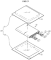
- FIG. 1 is an exploded perspective view illustrating construction of a pouch-type secondary battery according to a related art
- FIG. 2 is an assembled view illustrating the pouch-type secondary battery of FIG. 1 .
- the pouch-type secondary battery generally includes an electrode assembly 20, and a pouch case 30 to receive the electrode assembly 20 therein.
- the electrode assembly 20 has a basic structure of a cathode plate and an anode plate with a separator interposed therebetween, and is received in an internal space formed in the pouch case 30.
- the pouch case 30 may be made up of an upper pouch 31 and a lower pouch 32, and sealing parts are provided along the periphery of the upper pouch 31 and the lower pouch 32 and adhered to each other to hermetically seal the internal space in which the electrode assembly 20 is received.
- At least one cathode tab 21 and at least one anode tab 22 may extend from the cathode plate and the anode plate, respectively.
- the cathode tab 21 and the anode tab 22 are each joined with an electrode lead 10, that is, a cathode lead 11 and an anode lead 12, and parts of the cathode lead 11 and the anode lead 12 are exposed to the outside of the pouch case 30 to provide an electrode terminal to enable an electrical connection with an external element of the secondary battery, namely, another secondary battery or an external device.
- a mobile device to which a secondary battery is applied such as a laptop computer or a mobile phone, is increasingly used, and to meet the growing demand for performance and a usage time of a mobile device, an output and a capacity of a secondary battery in use is continuously increasing.
- the secondary battery may be damaged, which may lead to an accident such as an electric shock or a fire and an explosion, causing human life and property losses. Accordingly, various protection devices have been applied or is being attempted to ensure safety of a secondary battery.
- the gas generation may occur by various causes such as overcharging or overdischarging, a short circuit, and the like, and is problematic in that it may lead to damage of a secondary battery and even an explosion or a fire.
- a serious result may be produced, for example, users of a device to which the secondary battery is applied may be damaged, as well as the device.
- an electrolyte solution within the secondary battery leaks out, and as a consequence, damage such as a short circuit or an electric shock may occur.
- damage caused by internal gas generation may be more serious.
- the present disclosure is designed to solve the above problem, and therefore, the present disclosure is directed to providing a new-type electrode lead with improved safety constructed to discharge out gas generated within a secondary battery and cut off an electrical connection with the outside, and a secondary battery and a battery pack comprising the same according to the independent claims 1,19 and 20
- an electrode lead for electrically connecting an electrode assembly provided inside a case of a secondary battery to an outside of the case
- the electrode lead includes an inner lead interposed between sealing parts of the case, to which an electrode tab of the electrode assembly is attached, and having a gas flow path formed to allow gas to move between inside and outside of the case, and an outer lead constructed to be inserted into the gas flow path and electrically connected to the inner lead when inserted into the gas flow path, the outer lead which seals one end of the gas flow path and is separated from the gas flow path to cut off the electrical connection with the inner lead when pressure of gas flowed into the gas flow path is higher than or equal to a predetermined pressure.
- the inner lead is formed such that an appearance of a part interposed between the sealing parts is a circular shape or an oval shape.
- the inner lead is provided with a sealing member at a location where the inner lead comes into contact with the sealing part.
- the gas flow path has an electrode assembly side end of a cross sectional area becoming wider in a direction toward the electrode assembly.
- the electrode lead further includes a ring-type packing member between the outer lead and the inner lead.
- the inner lead has at least one gas flow path.
- a secondary battery according to the present disclosure includes the above electrode lead.
- a battery pack according to the present disclosure includes the above electrode lead.
- the generated gas in the secondary battery may be discharged out of the secondary battery by separation of an inner lead and an outer lead.
- a flow of electric current is interrupted in advance thereby to suppress additional gas generation within the secondary battery and prevent an electric shock or an explosion and a fire, and to interrupt a flow of electric current to an external device connected with the secondary battery, thereby preventing damage of the external device.
- FIG. 3 is an exploded perspective view schematically illustrating construction of a secondary battery according to an exemplary embodiment of the present disclosure
- FIG. 4 is an assembly view of the secondary battery of FIG. 3 .
- the secondary battery according to the present disclosure includes an electrode assembly 20, a case 30, and an electrode lead 100.
- the electrode assembly 20 is constructed in a structure in which at least one cathode plate and at least one anode plate are disposed with a separator interposed therebetween.
- the electrode assembly 20 may be received in the case 30 in a state that a plurality of cathode plates and a plurality of anode plates are stacked, or may be received in the case 30 in a state that one cathode plate and one anode plate are rolled.
- the electrode plates of the electrode assembly 20 are formed in a structure of a current collector coated with an active material slurry, and generally, the slurry may be prepared by stirring a particulate active material, an auxiliary conductive material, a binder, and a plasticizer with addition of a solvent.
- each electrode plate a part that is not coated with the slurry, namely, a non-coating part may be present, and on the non-coating part, an electrode tab corresponding to each electrode plate may be formed.
- a part that is not coated with the slurry namely, a non-coating part
- an electrode tab corresponding to each electrode plate may be formed.
- at least one cathode tab 21 and at least one anode tab 22 may be formed on the cathode plate and the anode plate, respectively.
- the cathode tab 21 or the anode tab 22 may be protrusively formed to be attached to the cathode plate or the anode plate, and each may be made of a same material as a cathode current collector or an anode current collector.
- the case 30 has an internal space of a concave shape, and the electrode assembly 20 and an electrolyte solution are received in the internal space.
- the secondary battery according to the present disclosure is preferably applied to a pouch-type secondary battery, and in this case, the case 30 may be constructed in an aluminum pouch type in which an aluminum thin film is interposed between an insulating layer and an adhesive layer made of polymer.
- the case 30 may be made up of an upper pouch 31 and a lower pouch 32 as shown in the drawing.
- a space for receiving the electrode assembly 20 may be formed in either the upper pouch 31 or the lower pouch 32 or both, as shown in FIG. 3 .
- an adhesive layer of a sealing part S1 of the upper pouch 31 and an adhesive layer of a sealing part S2 of the lower pouch 32 may be adhered by heat welding.
- the electrode lead 100 electrically connects the secondary battery to another external secondary battery or device. To do so, the electrode lead 100 is interposed between the sealing parts S of the case 30 of the secondary battery, and an inside end may protrude in a direction toward the electrode assembly 20 within the case 30 and an outside end may protrude out of the case 30.
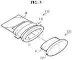
- FIG. 5 is a diagram illustrating construction in a state that an inner lead 110 and an outer lead 120 of the electrode lead 100 are separated according to the present disclosure
- FIG. 6 is a diagram illustrating construction in a state that the inner lead 110 and the outer lead 120 of the electrode lead 100 of FIG. 5 are assembled.
- the electrode lead 100 includes the inner lead 110 and the outer lead 120.
- the inner lead 110 is disposed in an inward direction of the secondary battery, that is, in a direction in which the electrode assembly 20 is present, among the electrode lead 100.
- the inner lead 110 may be attached to an electrode tab of the electrode assembly 20 at any one end. That is, the inner lead 110 may be attached to a cathode lead or an anode lead, and when the cathode tab 21 is attached, the inner lead may function as a cathode lead, and when the anode tab 22 is attached, the inner lead may function as an anode lead.
- the inner lead 110 has, at the inside end, an attachment area to which the electrode tab is attached, as indicated by W in FIG. 5 .
- the electrode tab of the electrode assembly 20 may be attached to the attachment area W of the inner lead 110.
- the attachment area W of the inner lead 10 preferably has a flat surface.
- At least a part of the inner lead 100 may be interposed between the sealing parts S of the case 30.
- FIG. 7 is a cross-sectional view of FIG. 4 taken along the line of A-A'.
- the inner lead 10 is interposed between the sealing part S1 of the upper pouch 31 and the sealing part S2 of the lower pouch 32, and preferably, the upper pouch 31 and the inner lead 110, and the lower pouch 32 and the inner lead 110 are closely adhered to maintain hermetical sealing of the case 30.
- an outer surface of the inside end of the inner lead 110 is closely adhered to an inner surface of the case 30 as indicated by D in FIG. 7 .
- an adhesive layer such as an adhesive tape may be provided between the outer surface of the inside end of the inner lead 110 and the inner surface of the case 30 coming into contact therewith, to adhere the inner lead 110 to the inner surface of the case 30.
- close adhesion of the inside end of the inner lead 110 and the case 30 is reliably achieved, thereby preventing a gap from being formed therebetween. If close adhesion of the outer surface of the inside end of the inner lead 110 and the inner surface of the case 30 is not made right, a gap is formed between the inside end of the inner lead 110 and the case 30, and some of the gas generated in the secondary battery may flow into the gap. Then, gas generated in the secondary battery fails to flow into a gas flow path well, and consequently, may fail to push out the outer lead 120 inserted into the gas flow path. As a result, even if the internal pressure of the secondary battery increases, the outer lead 120 may not be separated from the gas flow path of the inner lead 110.
- the inner lead 110 is preferably provided with a sealing member 113 at a location where the inner lead 110 comes into contact with the case 30. Because a material of the inner lead 110 is different from an adhesive layer material of the pouch, adhesion of the inner lead 110 and the case 30 may be poor, and the sealing member 113 enables good adhesion between the inner lead 110 and the case 30. Thus, according to this embodiment, the likelihood that a gap may be formed between the inner lead 110 and the case 30 is prevented, thereby improving hermetical sealing of the case 30 of the secondary battery and effectively preventing gas inside/outside of the secondary battery from flowing out/in or an electrolyte solution from flowing out between the inner lead 110 and the case 30. As the sealing member 113, a sealant may be used, but the present disclosure is not necessarily limited to this type of sealing member 113.
- an appearance of the part of the inner lead 110 interposed between the sealing parts S of the case 30 may be formed in an oval shape. Its description is provided with reference to FIG. 8 .
- FIG. 8 is a cross-sectional view of FIG. 4 taken along the line of B-B'.
- the part of the inner lead 110 coming into contact with the sealing part S of the case 30 may have an oval shape. Due to this shape of the inner lead 110, sealing between the inner lead 110 and the case 30 may be achieved more reliably. That is, in case in which the inner lead 110 has an angular shape such as a rectangular shape at the part coming into contact with the sealing part S of the case 30, sealing between the inner lead 110 and the case 30 is not made easy and thus, a gap may be generated between the inner lead 110 and the case 30.
- sealing with the case 30 may be further improved.
- FIGS. 9 and 10 are cross-sectional views schematically illustrating construction of the part of the inner lead 110 coming into contact with the sealing part S according to another exemplary embodiment of the present disclosure.
- an appearance of the part of the inner lead 110 coming into contact with the sealing part S may be constructed in a circular shape. Similar to the case in which the cross section has an oval shape, sealing between the case 30 and the inner lead 110 may be also improved in this embodiment.
- a portion of the appearance of the part of the inner lead 110 coming into contact with the sealing part S may have a round shape.
- the inner lead 110 may be rounded at corners and may be flat in the horizontal direction, whereby sealing between the case 30 and the inner lead 110 may be improved.
- the present disclosure is not necessarily limited by the inner leads 110 having these shapes, and besides, the appearance of the inner lead 110 at the part coming into contact with the sealing part S may be variously constructed.
- the inner lead 110 has a gas flow path formed as indicated by H in FIG. 5 .
- the gas flow path H may be formed through the inner lead 110, and in this instance, the penetration direction may be a direction between inside and outside of the case 30 when the inner lead 110 is mounted in the case 30. That is, describing focusing to FIG. 5 , because the electrode assembly 20 is disposed at the left side of the inner lead 110, the left side of the inner lead 110 will be an inward direction of the secondary battery and the right side will be an outward direction of the secondary battery, and the gas flow path H may be formed in the horizontal direction in the drawing.
- gas flow path H is formed in the inner lead 110
- gas flow path H of the inner lead 110 allows gas present in the case 30 to move out of the case 30.
- a case 30 is constructed to prevent gas from moving between inside and outside.
- the case 30 according to the present disclosure also has the sealing part S, but because the gas flow path H is formed in the inner lead 110 interposed between the sealing parts S, gas may move between inside and outside of the case 30.
- gas within the case 30 may be discharged out of the case 30 through the gas flow path H of the inner lead 110.
- the outer lead 120 is constructed to be inserted into the gas flow path H of the inner lead 110. Also, in a normal state, the outer lead 120 is inserted into the gas flow path H of the inner lead 110. Accordingly, in this case, gas fails to move between inside and outside of the case 30 through the gas flow path H.
- At least a portion of the outer lead 120 may be constructed in a shape corresponding to the gas flow path H of the inner lead 110. More specifically, referring to FIG. 5 , a part indicated by F1 among the outer lead 120 is constructed in a shape corresponding to the gas flow path H, and this part is inserted into the gas flow path H.
- the outer lead 120 When the secondary battery is in a normal state, the outer lead 120 is inserted into the gas flow path H of the inner lead 110, and in this case, the outer lead 120 is electrically connected to the inner lead 110. Accordingly, an electric current generated in the electrode assembly 20 may be provided outside the secondary battery through the inner lead 110 and the outer lead 120. Thus, in this state, the outer lead 120 provides another external element connected to the secondary battery, for example, an external terminal that may be connected to another secondary battery or an external device.
- the outer lead 120 when the outer lead 120 is inserted into the gas flow path H of the inner lead 110, the outer lead 120 hermetically seals one end of the gas flow path H. That is, as shown in FIG. 6 , the outer lead 120 is inserted into a right end of the gas flow path H to hermetically seal the right end of the gas flow path H. Also, like this, when the right end of the gas flow path H is hermetically sealed, gas fails to move between inside and outside of the case 30 of the secondary battery through the gas flow path H. Accordingly, in a normal state, the case 30 of the secondary battery becomes sealed. In this instance, to ensure sealing of the case 30, the inner lead 110 and the outer lead 120 are preferably completely closely adhered to each other to prevent the generation of a gap through which gas passes between the gas flow path and the insertion part F1.
- the outer lead 120 is preferably formed such that an outside part F2 of the part inserted into the gas flow path has a wider cross-sectional area than the part F1 inserted into the gas flow path H.
- sealing between the outer lead 120 and the inner lead 110 may be improved due to the protrusive shape of the outside part F2.
- gas inside or outside of the secondary battery may be prevented more effectively from leaking out or flowing inwards through the gas flow path H.
- the outer lead 120 may be separated from the gas flow path H.
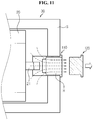
- FIG. 11 is a top cross-sectional view schematically illustrating construction in which the outer lead 120 is separated from the gas flow path H of the inner lead 110 due to the increased internal pressure, in the secondary battery according to an exemplary embodiment of the present disclosure.
- the cathode tab 21 and the electrode lead 100 connected thereto in the secondary battery are only illustrated.
- gas when the secondary battery is in an abnormal state, for example, overcharging, a short circuit, penetration, and the like, gas is generated from the electrode assembly 20 or the electrolyte solution, which may increase the internal pressure of the secondary battery, and in this case, gas may flow into the gas flow path H of the inner lead 110 as indicated by dotted arrows. Also, due to the in-flow of gas, when the pressure of the gas flow path H increases above a predetermined pressure, the outer lead 120 may be separated from the flow gas path H of the inner lead 110 as shown in the drawing.
- the predetermined pressure as a reference at which the outer lead 120 is separated from the gas flow path H may be variously determined based on various consideration factors, for example, specification or a type of the case 30, a type of a device to which the secondary battery is applied, and the like.
- the inner lead 110 and the outer lead 120 provide an electrical connection passage for the secondary battery, and thus, may include an electrically conductive material.
- the inner lead 110 and/or the outer lead 120 may be made of one electrically conductive material itself.
- the inner lead 110 and the outer lead 120 shown in FIG. 5 may be entirely made of a metal.
- the metal constituting the inner lead 110 and the outer lead 120 may include copper, aluminum, nickel, iron, chrome, gold, silver, and alloys thereof.
- the inner lead 110 and/or the outer lead 120 may be coated with an electrically non-conductive material on the outer surface of the electrically conductive material.
- a body of the inner lead 110 and/or the outer lead 120 is made of an electrically conductive material, and an outer surface of the body may be coated with an electrically non-conductive material.
- the conductive material of the inner lead 110 and/or the outer lead 120 is not exposed to the outside, prevention of electric current leaks may be facilitated and corrosion of the conductive material may be prevented.
- the inner lead 110 and/or the outer lead 120 is made of an electrically non-conductive material, and an electrically conductive material may be provided on the non-conductive material. This embodiment is described in more detail with reference to FIG. 12 .
- FIG. 12 is a top cross-sectional view schematically illustrating construction of the inner lead 110 and the outer lead 120 according to an exemplary embodiment of the present disclosure.
- the bodies of the inner lead 110 and the outer lead 120 may be each made of an electrically non-conductive material. Also, the inner lead 110 and the outer lead 120 may be each provided with an electrically conductive material.
- the inner lead 110 may have a pattern E1 made of an electrically conductive material formed from the attachment area W where the electrode tab is attached, to the inner surface of the gas flow path H.
- the outer lead 120 may have a pattern E2 made of an electrically conductive material from the outer surface of the part inserted into the gas flow path H to the outside end (the right end of the outer lead 120 in FIG. 12 ).
- the electrically conductive material may be provided, in various types such as coating or insertion, to the electrically non-conductive material.
- the electrically conductive material pattern E1 provided on the inner surface of the gas flow path H of the inner lead 110 comes into contact with the electrically conductive material pattern E2 provided on the outer surface of the insertion part of the outer lead 120.
- an electrical connection may be established from the attachment area W of the inner lead 110 to the outside end of the outer lead 120.
- FIG. 12 shows that the inner lead 110 and the outer lead 120 are provided with the electrically conductive material on the electrically non-conductive material, it is obvious that any one of the inner lead 110 and the outer lead 120 may be entirely made of an electrically conductive material, and the other may be entirely made of an electrically non-conductive material and have an electrically conductive material pattern formed thereon.
- the electrode lead 100 may be constructed such that the cathode tab 21 or the anode tab 22 is attached to the inner lead 110 as shown in FIG. 3 . That is, the secondary battery may have two electrode leads 100, and the cathode tab 21 of the electrode assembly 20 may be attached to an inner lead 110 of one electrode lead 100 and the anode tab 22 of the electrode assembly 20 may be attached to an inner lead 110 of the other electrode lead 100.
- a plurality of cathode tabs 21 and a plurality of anode tabs 22 may be provided in the electrode assembly 20, and in this case, the plurality of cathode tabs 21 may be attached to an inner lead 110 of one electrode lead 100, and the plurality of anode tabs 22 may be attached to an inner lead 110 of the other electrode lead 100.
- the plurality of cathode tabs 21 and the plurality of anode tabs 22 may be each attached to inner leads 110 of a plurality of electrode leads 100.
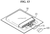
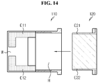
- the electrode lead 100 may be constructed such that both the cathode tab 21 and the anode tab 22 are attached to the inner lead 110. Its description is provided with reference to FIGS. 13 and 14 .
- FIG. 13 is a perspective view schematically illustrating construction of the secondary according to another exemplary embodiment of the present disclosure. In FIG. 13 , for the convenience of description, only a portion of the upper pouch is illustrated. Also, FIG. 14 is a top view schematically illustrating a process of forming an electrically conductive material for the inner lead 110 and the outer lead 120 shown in FIG. 13 .
- both the cathode tab 21 and the anode tab 22 may be attached to one inner lead 110.
- the inner lead 110 and the outer lead 120 may be made of an electrically non-conductive material.
- a pattern made of an electrically conductive material is formed on each of the inner lead 110 and the outer lead 120, to form two electrically connection passages.
- the inner lead 110 may have two electrically conductive material patterns E11 and E12 formed from the attachment area W of the electrode tab to the inner surface of the gas flow path H.
- the outer lead 120 may have two electrically conductive material patterns E21 and E22 formed from the outer surface of the part inserted into the gas flow path H to the outside end.
- the cathode tab 21 of the electrode assembly 20 is attached to the electrically conductive material pattern E11 and the anode tab 22 of the electrode assembly 20 is attached to the electrically conductive material pattern E12, when the outer lead 120 is inserted into the gas flow path H of the inner lead 110, the cathode tab 21 of the electrode assembly 20 may be electrically connected to the outside of the secondary battery through E11 and E21, and the anode tab 22 of the electrode assembly 20 may be electrically connected to the outside of the secondary battery through E12 and E22.
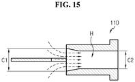
- the gas flow path H formed in the inner lead 110 may have a wider cross-sectional area of the inside end than that of the outside end. This embodiment is described with reference to FIG. 15 .
- FIG. 15 is a side cross-sectional view schematically illustrating construction of the inner lead 110 of the electrode lead 100 according to another exemplary embodiment of the present disclosure.
- the gas flow path H formed in the inner lead 110 may be constructed such that a cross sectional area of an inside end close to the electrode assembly 20 is wider than a cross sectional area of an outside end distant from the electrode assembly 20.
- a diameter C1 of the inside end close to the electrode assembly 20 left end of the gas flow path H in FIG. 15
- that of the outside end right end of the gas flow path H in FIG. 15 .
- a larger amount of gas generated in the secondary battery may flow into the gas flow path H of the inner lead 110 as indicated by arrows in FIG. 15 .
- separation of the outer lead 120 from the gas flow path H may be facilitated when the internal pressure of the secondary battery increases.
- FIG. 16 is a perspective view schematically illustrating construction in a state that the inner lead 110 and the outer lead 120 of the electrode lead 120 are separated according to another exemplary embodiment of the present disclosure.
- a ring-type packing member 130 may be further provided between the outer lead 120 and the inner lead 110.
- the ring-type packing member 130 When the ring-type packing member 130 is provided on the outer surface of the outer lead 120, and the outer lead 120 is inserted into the gas flow path H, the ring-type packing member 130 may be disposed between the outer lead 120 and the inner lead 110.
- sealing between the outer lead 120 and the inner lead 110 may be improved, and movement of gas between inside and outside of the secondary battery through the gas flow path H may be effectively blocked.
- a protrusion or a groove may be formed in the gas flow path H of the inner lead 100 according to the present disclosure. Also, a protrusion or groove corresponding to the protrusion or groove of the gas flow path H may be formed in the external lead 120.
- FIG. 17 is a side cross-sectional view schematically illustrating construction of the electrode lead 100 according to another exemplary embodiment of the present disclosure.
- a protrusion P is formed in the gas flow path H of the inner lead 100, and a groove G is formed in the inside end of the outer lead 120. Also, the protrusion P and the groove G are provided at corresponding locations, and when the outer lead 120 is inserted into the gas flow path H, the protrusion P of the gas flow path H may be inserted into and coupled with the grove G of the outer lead 120.
- the outer lead 120 may be stably coupled to the gas flow path H of the inner lead 110 until the pressure flowed into the gas flow path H reaches a predetermined pressure or higher.
- FIG. 17 shows that the protrusion P is formed in the gas flow path H and the groove G is formed in the outer lead 120
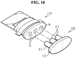
- FIG. 18 is a perspective view schematically illustrating construction of the electrode lead 100 according to another exemplary embodiment of the present disclosure.
- a plurality of gas flow paths H is formed in one inner lead 110. Also, corresponding to the gas flow paths H, a plurality of parts F1 inserted into the gas flow paths H are formed in the outer lead 120.
- FIG. 19 is a perspective view schematically illustrating construction of the electrode lead 100 according to another exemplary embodiment of the present disclosure.
- the gas flow path H of the inner lead 110 may be formed to have a rectangular shape in cross section. Also, in keeping with the shape of the gas flow path H, the part of the outer lead 120 inserted into the gas flow path H may be also constructed to have a rectangular shape in cross section.
- the gas flow path H formed in the inner lead may have various shapes.
- the inner lead 110 or the outer lead 120 may be constructed in various shapes.
- FIG. 20 is a perspective view schematically illustrating construction of the electrode lead 100 according to another exemplary embodiment of the present disclosure.
- the outer lead 120 may have a protrusive terminal F3 with a flat surface in a horizontal direction.
- the protrusive terminal F3 may be connected to an external terminal of another external element.
- a protrusive terminal of an outer lead provided in another secondary battery may be attached to the protrusive terminal F3 of the outer lead 120, so an electrical connection between the secondary batteries may be established.
- a connection with another external element may be easily established.
- the protrusive terminal F3 is for electrically connecting the secondary battery to another external element and thus may be made of an electrically conductive material.
- the secondary battery according to the present disclosure may include the above electrode lead 100.
- the above electrode lead 100 may be applied to both a cathode lead or an anode lead of a secondary battery. That is, the secondary battery according to the present disclosure includes two electrode leads 100 described above, one electrode lead 100 may be connected to the cathode tab 21 and function as a cathode lead, and the other electrode lead 100 may be connected to the anode tab 22 and function as an anode lead.
- the two electrode leads 100 may be disposed in the same direction in the case 30 of the secondary battery. That is, referring to FIGS. 3 and 4 , when the sealing part S of the case 30 of the secondary battery has four corners, two electrode leads 100 may be disposed at the same corner in the sealing part S of the case 30 of the secondary battery.
- the present disclosure is not limited to this embodiment.
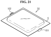
- FIGS. 21 and 22 are perspective views schematically illustrating construction of the secondary battery according to another exemplary embodiment of the present disclosure.
- two electrode leads 100 may be disposed, as shown in FIG. 21 , in the opposing directions in the sealing part S of the case 30 of the secondary battery. That is, the cathode lead 101 and the anode lead 102 may be provided at the corners located in the opposing directions among the four corners of the sealing part S of the case 30.
- two electrode leads 100 may be disposed, as shown in FIG. 22 , in mutually perpendicular directions in the sealing part S of the case 30 of the secondary battery. That is, the cathode lead 101 and the anode lead 102 may be each disposed at the adjacent corners among the four corners of the sealing part S of the case 30.
- the secondary battery according to the present disclosure includes one electrode lead 100 described above, as shown in FIG. 13 , and the electrode lead 100 may function as both a cathode lead and an anode lead.
- the above electrode lead 100 may be applied to only any one of a cathode lead and an anode lead of a secondary battery.
- the battery pack according to the present disclosure may include the above electrode lead 100.
- the battery pack may include one or more secondary battery, and in addition to the secondary battery, may include many protection devices for controlling the charge/discharge of the secondary battery, such as a battery management system (BMS).
- BMS battery management system
- the battery pack according to an exemplary embodiment of the present disclosure may include at least one secondary battery in which the above electrode lead 100 is used in a cathode lead and/or an anode lead.
- the battery pack according to another exemplary embodiment of the present disclosure may include a plurality of battery modules, and each battery module may include a plurality of cells.
- the above electrode lead 100 may be used to connect the battery modules.
Landscapes
- Chemical & Material Sciences (AREA)
- Chemical Kinetics & Catalysis (AREA)
- Electrochemistry (AREA)
- General Chemical & Material Sciences (AREA)
- Engineering & Computer Science (AREA)
- Manufacturing & Machinery (AREA)
- Connection Of Batteries Or Terminals (AREA)
- Sealing Battery Cases Or Jackets (AREA)
- Gas Exhaust Devices For Batteries (AREA)
- Battery Mounting, Suspending (AREA)
Applications Claiming Priority (2)
| Application Number | Priority Date | Filing Date | Title |
|---|---|---|---|
| KR1020120115941A KR101623110B1 (ko) | 2012-10-18 | 2012-10-18 | 전극 리드 및 이를 포함하는 이차 전지 |
| PCT/KR2013/009294 WO2014062016A1 (ko) | 2012-10-18 | 2013-10-17 | 전극 리드 및 이를 포함하는 이차 전지 |
Publications (3)
| Publication Number | Publication Date |
|---|---|
| EP2884563A1 EP2884563A1 (en) | 2015-06-17 |
| EP2884563A4 EP2884563A4 (en) | 2016-01-20 |
| EP2884563B1 true EP2884563B1 (en) | 2017-11-29 |
Family
ID=50488507
Family Applications (1)
| Application Number | Title | Priority Date | Filing Date |
|---|---|---|---|
| EP13847024.0A Active EP2884563B1 (en) | 2012-10-18 | 2013-10-17 | Electrode lead and secondary battery having same |
Country Status (6)
| Country | Link |
|---|---|
| US (1) | US9269945B2 (ko) |
| EP (1) | EP2884563B1 (ko) |
| JP (1) | JP6061162B2 (ko) |
| KR (1) | KR101623110B1 (ko) |
| CN (1) | CN104603985B (ko) |
| WO (1) | WO2014062016A1 (ko) |
Families Citing this family (28)
| Publication number | Priority date | Publication date | Assignee | Title |
|---|---|---|---|---|
| KR101704162B1 (ko) | 2015-01-20 | 2017-02-07 | 현대자동차주식회사 | 과충전 안전성이 향상된 파우치 전지 |
| KR101858317B1 (ko) * | 2015-05-07 | 2018-05-15 | 주식회사 엘지화학 | 전류 제한 기능의 전극리드를 포함하는 파우치형 이차전지 |
| WO2016200147A1 (ko) * | 2015-06-08 | 2016-12-15 | 주식회사 엘지화학 | 전극 리드 및 이를 포함하는 이차 전지 |
| KR102080903B1 (ko) * | 2015-06-08 | 2020-02-24 | 주식회사 엘지화학 | 전극 리드 및 이를 포함하는 이차 전지 |
| KR101755861B1 (ko) * | 2015-10-16 | 2017-07-07 | 현대자동차주식회사 | 배터리 셀 |
| US10109842B2 (en) * | 2015-10-16 | 2018-10-23 | Hyundai Motor Company | Battery cell |
| EP3159952B1 (de) * | 2015-10-19 | 2019-12-11 | Robert Bosch Gmbh | Sicherheitsvorrichtung für batteriesysteme |
| KR101766047B1 (ko) * | 2015-10-22 | 2017-08-07 | 현대자동차주식회사 | 배터리 셀 |
| KR101734703B1 (ko) * | 2015-11-04 | 2017-05-11 | 현대자동차주식회사 | 배터리 셀 |
| KR102106999B1 (ko) * | 2016-04-25 | 2020-05-06 | 주식회사 엘지화학 | 규격화된 구조에 기반하여 제조 공정성이 우수하면서도 전극리드의 절연 성능이 향상된 전지셀 및 이를 포함하는 전지팩 |
| KR102157892B1 (ko) * | 2016-08-26 | 2020-09-18 | 주식회사 엘지화학 | 파우치형 이차전지 |
| US10141550B2 (en) * | 2016-10-20 | 2018-11-27 | Ford Global Technologies, Llc | Pouch battery cell assembly for traction battery |
| KR102185959B1 (ko) * | 2017-04-25 | 2020-12-02 | 주식회사 엘지화학 | 안전성이 향상된 배터리 셀 |
| KR102294996B1 (ko) * | 2017-05-30 | 2021-08-30 | 주식회사 엘지에너지솔루션 | 전도성 튜브를 이용한 전극리드를 포함하는 이차전지 |
| KR102236056B1 (ko) | 2017-06-29 | 2021-04-05 | 주식회사 엘지화학 | 과충전 방지부재를 가지는 배터리 셀 |
| KR102348076B1 (ko) * | 2017-06-30 | 2022-01-10 | 에스케이온 주식회사 | 이차 전지 |
| KR101999529B1 (ko) * | 2017-07-06 | 2019-07-12 | 주식회사 엘지화학 | 노치가 형성된 리드박스를 포함하는 파우치형 이차전지 |
| KR102255534B1 (ko) | 2017-07-07 | 2021-05-25 | 주식회사 엘지에너지솔루션 | 이차전지 |
| KR102364159B1 (ko) * | 2017-08-01 | 2022-02-18 | 주식회사 엘지에너지솔루션 | 전극 탭 절단 장치를 포함하는 파우치형 이차전지 |
| KR102268402B1 (ko) * | 2017-08-29 | 2021-06-24 | 주식회사 엘지에너지솔루션 | 파우치 형 이차 전지 |
| KR102555751B1 (ko) * | 2017-10-17 | 2023-07-14 | 주식회사 엘지에너지솔루션 | 가스 배출이 가능한 이차전지용 파우치형 케이스 |
| KR102164254B1 (ko) * | 2017-11-15 | 2020-10-12 | 주식회사 엘지화학 | 이차 전지 및 그의 제조 방법, 이차 전지용 파우치 및 그의 제조 방법 |
| KR102314575B1 (ko) * | 2018-01-12 | 2021-10-20 | 주식회사 엘지에너지솔루션 | 이차전지의 충방전기 및 이를 포함하는 이차전지의 활성화 공정 장치 |
| KR102519040B1 (ko) * | 2018-06-26 | 2023-04-07 | 주식회사 엘지에너지솔루션 | 벤팅 장치, 벤팅 방법 및 이차 전지 |
| KR20210058143A (ko) * | 2019-11-13 | 2021-05-24 | 주식회사 엘지에너지솔루션 | 배터리 모듈, 이러한 배터리 모듈의 제조 방법 및 이러한 배터리 모듈을 포함하는 배터리 팩 및 자동차 |
| KR20220059186A (ko) * | 2020-11-02 | 2022-05-10 | 주식회사 엘지에너지솔루션 | 내압을 일정하게 유지할 수 있는 전극리드를 포함하는 파우치형 전지셀 및 이를 포함하는 전지팩 |
| KR20230155248A (ko) * | 2022-05-03 | 2023-11-10 | 에스케이온 주식회사 | 파우치형 이차전지 |
| WO2023243774A1 (ko) * | 2022-06-14 | 2023-12-21 | 주식회사 엘지에너지솔루션 | 배터리 셀, 배터리 모듈, 배터리 팩 및 이를 포함하는 자동차 |
Family Cites Families (11)
| Publication number | Priority date | Publication date | Assignee | Title |
|---|---|---|---|---|
| JPH07201309A (ja) * | 1993-12-28 | 1995-08-04 | Fuji Elelctrochem Co Ltd | 防爆形電池の封口構造 |
| JPH08287894A (ja) * | 1995-04-11 | 1996-11-01 | Mitsubishi Cable Ind Ltd | 密閉電池の安全装置 |
| JP4354028B2 (ja) * | 1998-08-20 | 2009-10-28 | 大日本印刷株式会社 | 安全弁付き電池ケース |
| JP2000277064A (ja) * | 1999-03-29 | 2000-10-06 | Sanyo Electric Co Ltd | 薄型電池 |
| JP4923389B2 (ja) * | 2004-05-28 | 2012-04-25 | 株式会社Gsユアサ | 密閉形蓄電池 |
| JP5288685B2 (ja) | 2006-03-10 | 2013-09-11 | 三洋電機株式会社 | 電池の安全装置 |
| KR101037042B1 (ko) * | 2007-12-10 | 2011-05-26 | 주식회사 엘지화학 | 안전성이 개선된 파우치형 이차전지 |
| KR101192077B1 (ko) * | 2009-11-02 | 2012-10-17 | 삼성에스디아이 주식회사 | 이차 전지 및 그를 이용한 전지 팩 |
| US20110104520A1 (en) | 2009-11-02 | 2011-05-05 | Changbum Ahn | Secondary battery and battery pack using the same |
| KR101147791B1 (ko) * | 2009-12-29 | 2012-05-18 | 주식회사 루트제이드 | 벤트홀을 구비하는 이차전지 |
| KR101201808B1 (ko) * | 2010-06-03 | 2012-11-15 | 삼성에스디아이 주식회사 | 이차 전지 및 이차 전지의 전해액 주입 방법 |
-
2012
- 2012-10-18 KR KR1020120115941A patent/KR101623110B1/ko active IP Right Grant
-
2013
- 2013-10-17 WO PCT/KR2013/009294 patent/WO2014062016A1/ko active Application Filing
- 2013-10-17 JP JP2015538024A patent/JP6061162B2/ja active Active
- 2013-10-17 CN CN201380045998.0A patent/CN104603985B/zh active Active
- 2013-10-17 EP EP13847024.0A patent/EP2884563B1/en active Active
-
2014
- 2014-11-18 US US14/546,367 patent/US9269945B2/en active Active
Non-Patent Citations (1)
| Title |
|---|
| None * |
Also Published As
| Publication number | Publication date |
|---|---|
| WO2014062016A1 (ko) | 2014-04-24 |
| JP6061162B2 (ja) | 2017-01-18 |
| EP2884563A4 (en) | 2016-01-20 |
| KR20140049748A (ko) | 2014-04-28 |
| CN104603985B (zh) | 2017-04-12 |
| JP2015536536A (ja) | 2015-12-21 |
| CN104603985A (zh) | 2015-05-06 |
| EP2884563A1 (en) | 2015-06-17 |
| US9269945B2 (en) | 2016-02-23 |
| US20150072185A1 (en) | 2015-03-12 |
| KR101623110B1 (ko) | 2016-05-20 |
Similar Documents
| Publication | Publication Date | Title |
|---|---|---|
| EP2884563B1 (en) | Electrode lead and secondary battery having same | |
| CN109473572B (zh) | 具有利用排出气体断开连接器的结构的电池模块 | |
| KR101991058B1 (ko) | 파우치형 이차전지 및 그의 제조방법 | |
| US20040126650A1 (en) | Electrode assembly for lithium ion cell and lithium cell using the same | |
| EP2056376A1 (en) | Electrode assembly and secondary battery having the same | |
| JP7062181B2 (ja) | パウチ型二次電池 | |
| KR101734703B1 (ko) | 배터리 셀 | |
| US20090162749A1 (en) | Electrode tab for secondary battery and secondary battery using the same | |
| KR20040100264A (ko) | 파우치형 리튬 이차 전지와 이의 제조 방법 | |
| KR102292159B1 (ko) | 전도성 폴리머를 이용한 전극리드를 포함하는 파우치형 이차전지 | |
| KR20080049547A (ko) | 원통형 이차전지 | |
| KR102593582B1 (ko) | 이차 전지 | |
| KR102414770B1 (ko) | 파우치용 테이프 및 파우치용 테이프가 부착된 이차 전지 | |
| KR101459179B1 (ko) | 파우치형 이차 전지 | |
| KR102080903B1 (ko) | 전극 리드 및 이를 포함하는 이차 전지 | |
| KR20120050207A (ko) | 파우치형 이차 전지의 제조 방법 및 이에 의한 파우치형 이차 전지 | |
| KR101520152B1 (ko) | 파우치형 이차전지 | |
| KR101734327B1 (ko) | 파우치형 이차전지 | |
| KR20050020894A (ko) | 전극탭을 캔의 단변부에 위치시킨 이차전지 | |
| KR101121205B1 (ko) | 이차전지 | |
| KR101576597B1 (ko) | 이차 전지 및 이를 포함하는 배터리 팩 | |
| JP7414129B2 (ja) | 二次電池 | |
| KR101243550B1 (ko) | 고정부재를 이용한 안정성이 향상된 이차전지 | |
| KR102294996B1 (ko) | 전도성 튜브를 이용한 전극리드를 포함하는 이차전지 | |
| KR20140014982A (ko) | 두가지 금속이 결합된 전극리드를 포함하는 전지팩 |
Legal Events
| Date | Code | Title | Description |
|---|---|---|---|
| PUAI | Public reference made under article 153(3) epc to a published international application that has entered the european phase |
Free format text: ORIGINAL CODE: 0009012 |
|
| 17P | Request for examination filed |
Effective date: 20150313 |
|
| AK | Designated contracting states |
Kind code of ref document: A1 Designated state(s): AL AT BE BG CH CY CZ DE DK EE ES FI FR GB GR HR HU IE IS IT LI LT LU LV MC MK MT NL NO PL PT RO RS SE SI SK SM TR |
|
| AX | Request for extension of the european patent |
Extension state: BA ME |
|
| RA4 | Supplementary search report drawn up and despatched (corrected) |
Effective date: 20151222 |
|
| RIC1 | Information provided on ipc code assigned before grant |
Ipc: H01M 2/26 20060101AFI20151216BHEP Ipc: H01M 2/30 20060101ALI20151216BHEP Ipc: H01M 10/02 20060101ALI20151216BHEP |
|
| DAX | Request for extension of the european patent (deleted) | ||
| GRAP | Despatch of communication of intention to grant a patent |
Free format text: ORIGINAL CODE: EPIDOSNIGR1 |
|
| INTG | Intention to grant announced |
Effective date: 20170810 |
|
| GRAS | Grant fee paid |
Free format text: ORIGINAL CODE: EPIDOSNIGR3 |
|
| GRAA | (expected) grant |
Free format text: ORIGINAL CODE: 0009210 |
|
| AK | Designated contracting states |
Kind code of ref document: B1 Designated state(s): AL AT BE BG CH CY CZ DE DK EE ES FI FR GB GR HR HU IE IS IT LI LT LU LV MC MK MT NL NO PL PT RO RS SE SI SK SM TR |
|
| REG | Reference to a national code |
Ref country code: CH Ref legal event code: EP |
|
| REG | Reference to a national code |
Ref country code: AT Ref legal event code: REF Ref document number: 951164 Country of ref document: AT Kind code of ref document: T Effective date: 20171215 |
|
| REG | Reference to a national code |
Ref country code: IE Ref legal event code: FG4D |
|
| REG | Reference to a national code |
Ref country code: DE Ref legal event code: R096 Ref document number: 602013030230 Country of ref document: DE |
|
| REG | Reference to a national code |
Ref country code: NL Ref legal event code: MP Effective date: 20171129 |
|
| REG | Reference to a national code |
Ref country code: LT Ref legal event code: MG4D |
|
| REG | Reference to a national code |
Ref country code: AT Ref legal event code: MK05 Ref document number: 951164 Country of ref document: AT Kind code of ref document: T Effective date: 20171129 |
|
| PG25 | Lapsed in a contracting state [announced via postgrant information from national office to epo] |
Ref country code: LT Free format text: LAPSE BECAUSE OF FAILURE TO SUBMIT A TRANSLATION OF THE DESCRIPTION OR TO PAY THE FEE WITHIN THE PRESCRIBED TIME-LIMIT Effective date: 20171129 Ref country code: SE Free format text: LAPSE BECAUSE OF FAILURE TO SUBMIT A TRANSLATION OF THE DESCRIPTION OR TO PAY THE FEE WITHIN THE PRESCRIBED TIME-LIMIT Effective date: 20171129 Ref country code: FI Free format text: LAPSE BECAUSE OF FAILURE TO SUBMIT A TRANSLATION OF THE DESCRIPTION OR TO PAY THE FEE WITHIN THE PRESCRIBED TIME-LIMIT Effective date: 20171129 Ref country code: NO Free format text: LAPSE BECAUSE OF FAILURE TO SUBMIT A TRANSLATION OF THE DESCRIPTION OR TO PAY THE FEE WITHIN THE PRESCRIBED TIME-LIMIT Effective date: 20180228 Ref country code: ES Free format text: LAPSE BECAUSE OF FAILURE TO SUBMIT A TRANSLATION OF THE DESCRIPTION OR TO PAY THE FEE WITHIN THE PRESCRIBED TIME-LIMIT Effective date: 20171129 |
|
| PG25 | Lapsed in a contracting state [announced via postgrant information from national office to epo] |
Ref country code: BG Free format text: LAPSE BECAUSE OF FAILURE TO SUBMIT A TRANSLATION OF THE DESCRIPTION OR TO PAY THE FEE WITHIN THE PRESCRIBED TIME-LIMIT Effective date: 20180228 Ref country code: AT Free format text: LAPSE BECAUSE OF FAILURE TO SUBMIT A TRANSLATION OF THE DESCRIPTION OR TO PAY THE FEE WITHIN THE PRESCRIBED TIME-LIMIT Effective date: 20171129 Ref country code: RS Free format text: LAPSE BECAUSE OF FAILURE TO SUBMIT A TRANSLATION OF THE DESCRIPTION OR TO PAY THE FEE WITHIN THE PRESCRIBED TIME-LIMIT Effective date: 20171129 Ref country code: GR Free format text: LAPSE BECAUSE OF FAILURE TO SUBMIT A TRANSLATION OF THE DESCRIPTION OR TO PAY THE FEE WITHIN THE PRESCRIBED TIME-LIMIT Effective date: 20180301 Ref country code: HR Free format text: LAPSE BECAUSE OF FAILURE TO SUBMIT A TRANSLATION OF THE DESCRIPTION OR TO PAY THE FEE WITHIN THE PRESCRIBED TIME-LIMIT Effective date: 20171129 Ref country code: LV Free format text: LAPSE BECAUSE OF FAILURE TO SUBMIT A TRANSLATION OF THE DESCRIPTION OR TO PAY THE FEE WITHIN THE PRESCRIBED TIME-LIMIT Effective date: 20171129 |
|
| PG25 | Lapsed in a contracting state [announced via postgrant information from national office to epo] |
Ref country code: NL Free format text: LAPSE BECAUSE OF FAILURE TO SUBMIT A TRANSLATION OF THE DESCRIPTION OR TO PAY THE FEE WITHIN THE PRESCRIBED TIME-LIMIT Effective date: 20171129 |
|
| PG25 | Lapsed in a contracting state [announced via postgrant information from national office to epo] |
Ref country code: SK Free format text: LAPSE BECAUSE OF FAILURE TO SUBMIT A TRANSLATION OF THE DESCRIPTION OR TO PAY THE FEE WITHIN THE PRESCRIBED TIME-LIMIT Effective date: 20171129 Ref country code: DK Free format text: LAPSE BECAUSE OF FAILURE TO SUBMIT A TRANSLATION OF THE DESCRIPTION OR TO PAY THE FEE WITHIN THE PRESCRIBED TIME-LIMIT Effective date: 20171129 Ref country code: EE Free format text: LAPSE BECAUSE OF FAILURE TO SUBMIT A TRANSLATION OF THE DESCRIPTION OR TO PAY THE FEE WITHIN THE PRESCRIBED TIME-LIMIT Effective date: 20171129 Ref country code: CZ Free format text: LAPSE BECAUSE OF FAILURE TO SUBMIT A TRANSLATION OF THE DESCRIPTION OR TO PAY THE FEE WITHIN THE PRESCRIBED TIME-LIMIT Effective date: 20171129 Ref country code: CY Free format text: LAPSE BECAUSE OF FAILURE TO SUBMIT A TRANSLATION OF THE DESCRIPTION OR TO PAY THE FEE WITHIN THE PRESCRIBED TIME-LIMIT Effective date: 20171129 |
|
| REG | Reference to a national code |
Ref country code: DE Ref legal event code: R097 Ref document number: 602013030230 Country of ref document: DE |
|
| PG25 | Lapsed in a contracting state [announced via postgrant information from national office to epo] |
Ref country code: SM Free format text: LAPSE BECAUSE OF FAILURE TO SUBMIT A TRANSLATION OF THE DESCRIPTION OR TO PAY THE FEE WITHIN THE PRESCRIBED TIME-LIMIT Effective date: 20171129 Ref country code: PL Free format text: LAPSE BECAUSE OF FAILURE TO SUBMIT A TRANSLATION OF THE DESCRIPTION OR TO PAY THE FEE WITHIN THE PRESCRIBED TIME-LIMIT Effective date: 20171129 Ref country code: RO Free format text: LAPSE BECAUSE OF FAILURE TO SUBMIT A TRANSLATION OF THE DESCRIPTION OR TO PAY THE FEE WITHIN THE PRESCRIBED TIME-LIMIT Effective date: 20171129 Ref country code: IT Free format text: LAPSE BECAUSE OF FAILURE TO SUBMIT A TRANSLATION OF THE DESCRIPTION OR TO PAY THE FEE WITHIN THE PRESCRIBED TIME-LIMIT Effective date: 20171129 |
|
| REG | Reference to a national code |
Ref country code: FR Ref legal event code: PLFP Year of fee payment: 6 |
|
| PLBE | No opposition filed within time limit |
Free format text: ORIGINAL CODE: 0009261 |
|
| STAA | Information on the status of an ep patent application or granted ep patent |
Free format text: STATUS: NO OPPOSITION FILED WITHIN TIME LIMIT |
|
| 26N | No opposition filed |
Effective date: 20180830 |
|
| PG25 | Lapsed in a contracting state [announced via postgrant information from national office to epo] |
Ref country code: SI Free format text: LAPSE BECAUSE OF FAILURE TO SUBMIT A TRANSLATION OF THE DESCRIPTION OR TO PAY THE FEE WITHIN THE PRESCRIBED TIME-LIMIT Effective date: 20171129 |
|
| REG | Reference to a national code |
Ref country code: CH Ref legal event code: PL |
|
| REG | Reference to a national code |
Ref country code: BE Ref legal event code: MM Effective date: 20181031 |
|
| PG25 | Lapsed in a contracting state [announced via postgrant information from national office to epo] |
Ref country code: MC Free format text: LAPSE BECAUSE OF FAILURE TO SUBMIT A TRANSLATION OF THE DESCRIPTION OR TO PAY THE FEE WITHIN THE PRESCRIBED TIME-LIMIT Effective date: 20171129 Ref country code: LU Free format text: LAPSE BECAUSE OF NON-PAYMENT OF DUE FEES Effective date: 20181017 |
|
| REG | Reference to a national code |
Ref country code: IE Ref legal event code: MM4A |
|
| PG25 | Lapsed in a contracting state [announced via postgrant information from national office to epo] |
Ref country code: LI Free format text: LAPSE BECAUSE OF NON-PAYMENT OF DUE FEES Effective date: 20181031 Ref country code: BE Free format text: LAPSE BECAUSE OF NON-PAYMENT OF DUE FEES Effective date: 20181031 Ref country code: CH Free format text: LAPSE BECAUSE OF NON-PAYMENT OF DUE FEES Effective date: 20181031 |
|
| PG25 | Lapsed in a contracting state [announced via postgrant information from national office to epo] |
Ref country code: IE Free format text: LAPSE BECAUSE OF NON-PAYMENT OF DUE FEES Effective date: 20181017 |
|
| PG25 | Lapsed in a contracting state [announced via postgrant information from national office to epo] |
Ref country code: MT Free format text: LAPSE BECAUSE OF NON-PAYMENT OF DUE FEES Effective date: 20181017 |
|
| PG25 | Lapsed in a contracting state [announced via postgrant information from national office to epo] |
Ref country code: TR Free format text: LAPSE BECAUSE OF FAILURE TO SUBMIT A TRANSLATION OF THE DESCRIPTION OR TO PAY THE FEE WITHIN THE PRESCRIBED TIME-LIMIT Effective date: 20171129 |
|
| PG25 | Lapsed in a contracting state [announced via postgrant information from national office to epo] |
Ref country code: PT Free format text: LAPSE BECAUSE OF FAILURE TO SUBMIT A TRANSLATION OF THE DESCRIPTION OR TO PAY THE FEE WITHIN THE PRESCRIBED TIME-LIMIT Effective date: 20171129 |
|
| PG25 | Lapsed in a contracting state [announced via postgrant information from national office to epo] |
Ref country code: HU Free format text: LAPSE BECAUSE OF FAILURE TO SUBMIT A TRANSLATION OF THE DESCRIPTION OR TO PAY THE FEE WITHIN THE PRESCRIBED TIME-LIMIT; INVALID AB INITIO Effective date: 20131017 Ref country code: MK Free format text: LAPSE BECAUSE OF NON-PAYMENT OF DUE FEES Effective date: 20171129 |
|
| PG25 | Lapsed in a contracting state [announced via postgrant information from national office to epo] |
Ref country code: AL Free format text: LAPSE BECAUSE OF FAILURE TO SUBMIT A TRANSLATION OF THE DESCRIPTION OR TO PAY THE FEE WITHIN THE PRESCRIBED TIME-LIMIT Effective date: 20171129 Ref country code: IS Free format text: LAPSE BECAUSE OF FAILURE TO SUBMIT A TRANSLATION OF THE DESCRIPTION OR TO PAY THE FEE WITHIN THE PRESCRIBED TIME-LIMIT Effective date: 20180329 |
|
| REG | Reference to a national code |
Ref country code: DE Ref legal event code: R079 Ref document number: 602013030230 Country of ref document: DE Free format text: PREVIOUS MAIN CLASS: H01M0002260000 Ipc: H01M0050531000 |
|
| P01 | Opt-out of the competence of the unified patent court (upc) registered |
Effective date: 20230512 |
|
| REG | Reference to a national code |
Ref country code: DE Ref legal event code: R081 Ref document number: 602013030230 Country of ref document: DE Owner name: LG ENERGY SOLUTION, LTD., KR Free format text: FORMER OWNER: LG CHEM. LTD., SEOUL, KR |
|
| REG | Reference to a national code |
Ref country code: GB Ref legal event code: 732E Free format text: REGISTERED BETWEEN 20230824 AND 20230831 |
|
| PGFP | Annual fee paid to national office [announced via postgrant information from national office to epo] |
Ref country code: GB Payment date: 20230920 Year of fee payment: 11 |
|
| PGFP | Annual fee paid to national office [announced via postgrant information from national office to epo] |
Ref country code: FR Payment date: 20230922 Year of fee payment: 11 |
|
| PGFP | Annual fee paid to national office [announced via postgrant information from national office to epo] |
Ref country code: DE Payment date: 20230920 Year of fee payment: 11 |