EP2884515A1 - Device switch for electric tools with a locking switch - Google Patents
Device switch for electric tools with a locking switch Download PDFInfo
- Publication number
- EP2884515A1 EP2884515A1 EP13197454.5A EP13197454A EP2884515A1 EP 2884515 A1 EP2884515 A1 EP 2884515A1 EP 13197454 A EP13197454 A EP 13197454A EP 2884515 A1 EP2884515 A1 EP 2884515A1
- Authority
- EP
- European Patent Office
- Prior art keywords
- switch
- pusher
- machine tool
- locking
- counter
- Prior art date
- Legal status (The legal status is an assumption and is not a legal conclusion. Google has not performed a legal analysis and makes no representation as to the accuracy of the status listed.)
- Withdrawn
Links
Images


Classifications
-
- H—ELECTRICITY
- H01—ELECTRIC ELEMENTS
- H01H—ELECTRIC SWITCHES; RELAYS; SELECTORS; EMERGENCY PROTECTIVE DEVICES
- H01H21/00—Switches operated by an operating part in the form of a pivotable member acted upon directly by a solid body, e.g. by a hand
- H01H21/02—Details
- H01H21/18—Movable parts; Contacts mounted thereon
- H01H21/22—Operating parts, e.g. handle
-
- H—ELECTRICITY
- H01—ELECTRIC ELEMENTS
- H01H—ELECTRIC SWITCHES; RELAYS; SELECTORS; EMERGENCY PROTECTIVE DEVICES
- H01H3/00—Mechanisms for operating contacts
- H01H3/02—Operating parts, i.e. for operating driving mechanism by a mechanical force external to the switch
- H01H3/20—Operating parts, i.e. for operating driving mechanism by a mechanical force external to the switch wherein an auxiliary movement thereof, or of an attachment thereto, is necessary before the main movement is possible or effective, e.g. for unlatching, for coupling
-
- B—PERFORMING OPERATIONS; TRANSPORTING
- B25—HAND TOOLS; PORTABLE POWER-DRIVEN TOOLS; MANIPULATORS
- B25F—COMBINATION OR MULTI-PURPOSE TOOLS NOT OTHERWISE PROVIDED FOR; DETAILS OR COMPONENTS OF PORTABLE POWER-DRIVEN TOOLS NOT PARTICULARLY RELATED TO THE OPERATIONS PERFORMED AND NOT OTHERWISE PROVIDED FOR
- B25F5/00—Details or components of portable power-driven tools not particularly related to the operations performed and not otherwise provided for
- B25F5/02—Construction of casings, bodies or handles
-
- H—ELECTRICITY
- H01—ELECTRIC ELEMENTS
- H01H—ELECTRIC SWITCHES; RELAYS; SELECTORS; EMERGENCY PROTECTIVE DEVICES
- H01H21/00—Switches operated by an operating part in the form of a pivotable member acted upon directly by a solid body, e.g. by a hand
- H01H21/02—Details
- H01H21/04—Cases; Covers
- H01H21/10—Casing of switch constituted by a handle serving a purpose other than the actuation of the switch
-
- H—ELECTRICITY
- H01—ELECTRIC ELEMENTS
- H01H—ELECTRIC SWITCHES; RELAYS; SELECTORS; EMERGENCY PROTECTIVE DEVICES
- H01H21/00—Switches operated by an operating part in the form of a pivotable member acted upon directly by a solid body, e.g. by a hand
- H01H21/02—Details
- H01H21/18—Movable parts; Contacts mounted thereon
- H01H21/22—Operating parts, e.g. handle
- H01H21/24—Operating parts, e.g. handle biased to return to normal position upon removal of operating force
- H01H21/245—Operating parts, e.g. handle biased to return to normal position upon removal of operating force the contact returning to its original state upon the next application of operating force
-
- H—ELECTRICITY
- H01—ELECTRIC ELEMENTS
- H01H—ELECTRIC SWITCHES; RELAYS; SELECTORS; EMERGENCY PROTECTIVE DEVICES
- H01H9/00—Details of switching devices, not covered by groups H01H1/00 - H01H7/00
- H01H9/02—Bases, casings, or covers
- H01H9/06—Casing of switch constituted by a handle serving a purpose other than the actuation of the switch, e.g. by the handle of a vacuum cleaner
-
- H—ELECTRICITY
- H01—ELECTRIC ELEMENTS
- H01H—ELECTRIC SWITCHES; RELAYS; SELECTORS; EMERGENCY PROTECTIVE DEVICES
- H01H2300/00—Orthogonal indexing scheme relating to electric switches, relays, selectors or emergency protective devices covered by H01H
- H01H2300/024—Avoid unwanted operation
Definitions
- the present invention relates to a switch device for turning on and off a machine tool, comprising a pusher element which is reversibly pivotable about a pivot point between a switch-on and a switch-off position, wherein in the switch-on position the machine tool is switched on and in the switch-off position the machine tool is switched off; and a locking means for releasably locking the pusher member in the on position.
- Such switch devices are widely known and find above all for an electrical machine tool with an electric motor, such as drills, grinders, saws, planer, angle grinder or the like, use.
- the machine tool can be a battery-powered and / or mains-operated machine tool.
- an electrical switch with a housing for a power tool is known.
- the housing contains a contact system.
- An actuator disposed on the housing is movable between an output and an end position.
- the actuator acts in the end position switching on the contact system.
- the switch can be provided with a switch-lock for the actuator in the starting position and / or with a locking device for the actuator in the end position.
- the switch-on lock and / or the lock comprises an actuating element and in each case one cooperating with the actuating element blocking element, which may be arranged on the housing.
- an electrical switch suitable for use in an electric hand tool with an electric motor is shown.
- the switch has for this purpose a housing in which a contact system is located. On the housing a movable between an initial position and an end position actuator is arranged for switching action on the contact system.
- the switch may optionally be provided with a switch-lock and / or a lock for the actuator, wherein the switch-on and / or the lock comprises an actuating element and a locking element cooperating with the actuating element.
- the blocking element is arranged on the housing such that the blocking element upon movement of the actuating member in the end position is immersed in a recess in the actuator.
- the blocking element is designed such that an optional interaction with the actuating element for the switch-on and / or for locking is possible.
- switch devices of the prior art are often designed very complex and space-consuming, so that for reasons of space in the respective switch device, either only a locking device that holds the switch element in a power-on mode, or only a transport lock, which in a transport of the machine tool, the switching element locks, can be realized.
- a switch device in which both a locking device and a transport lock can be integrated, is therefore possible only by a substantial enlargement of the entire switch device.
- switch devices of the prior art also often have the problem that the locking device can again loosen under strong vibrations, such as may occur during use of the machine tool, and the machine tool is unintentionally switched off again.
- a switch apparatus for turning on and off a machine tool including a pusher member reversibly pivotable about a pivot point between a switch-on position and a switch-off position, wherein in the switch-on position, the machine tool is turned on and in the switch-off position, the machine tool is turned off; and a locking means for releasably locking the pusher member in the on position provided.
- the locking device comprises a stop element and the pusher element comprises a counter-stop element, wherein the stop element reversibly between a locking position, in which the stop element bears against the counter stop element and the pusher element is held in the on position, and a release position in which the pusher element in the switch-off position is traceable is movable.
- the stop element has a beveled abutment surface and the counter stop element has a counterstop surface which corresponds to the bevelled abutment surface.
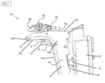
- Fig. 1 to 5 show a switch device 1 according to the invention for switching on and off a machine tool.
- the machine tool is, for example, a drill, a rotary hammer, a grinder, a saw, a planer, an angle grinder or the like with an electric motor.
- the machine tool is not shown in any figure.
- the switch device 1 essentially comprises a pusher element 10, switch housing 20 and a locking device 30.
- the pusher element 10 in turn contains an L-shaped switching element 11, a compression spring 15 and an unlocking switch 16.
- the L-shaped switching element 11 consists of a first (short) portion 12 and a second (long) portion 14th
- the first portion 12 includes a first end 12a, a second end 12b, a first surface 12c, and a second surface 12d.
- the second portion 14 also includes a first end 14a, a second end 14b, a first surface 14c, and a second surface 14d.
- the first surface 14c of the second portion 14 serves, in particular, as support surface for the fingers (not shown) of a user who wishes to press the pusher element 10 to switch on the machine tool.
- the second surface 14d of the second portion 14 includes a contact member (not shown) for actuating a mating contact member 13 on the switch housing 20 when the pusher member 10 is pivoted relative to the switch housing 20.
- the second end 12b of the first portion 12 is fixedly connected to the first end 14a of the second portion 14.
- the second end 14b of the second portion 14 includes a Schenkddling S on the pivot axis R by which the switching element 11 can be pivoted (see. Fig. 5 ).
- the switching element 11 is pivotally connected to the switch housing 20.
- the pivoting about the pivot point S serves to reversibly move the switching element 11 between a switch-off position and a switch-on position and relative to the switch housing 20 and also relative to the locking device 30.
- the compression spring 15 is positioned on the first portion 12 of the switching element 11 and is thus located between the switching element 11 and switch housing 20.
- the compression spring 15 serves the pusher element 10 and the switching element 11 automatically move back from the closed position to the off position.
- the unlocking switch 16 serves as a transport lock and prevents, if it is not pressed, that the pusher element 10 pivoted and started the machine tool can be.
- the unlocking switch 16 is pivotally mounted on the first surface 14 c of the second portion 14 between the first portion 12 and the second portion 14 of the switching element 11.
- Fig. 1 shows the unlocking switch 16 in a first position G (dashed line) in which the unlocking switch 16 is not actuated and the pusher member 10 is locked, and in a second position E (solid line) in which the unlocking switch 16 is actuated and the pusher member 10 is not is more blocked.
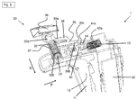
- the locking device 30 essentially comprises a cylindrical base body 32, an actuating switch 36, a stop element 38 and a counter-stop element 40.
- the cylindrical body 32 includes a first end 32a, a second end 32b, and a cylindrical cavity 33. At the first end 32a of the cylindrical body 32, the operation switch 36 is positioned. In the cavity 33 is a compression coil spring 37th
- the stopper member 38 includes an elongate body 39 having a first end 39a and a second end 39b.
- the abutment element 38 is positioned with the first end 39a of the elongate base body 39 on the lateral surface of the cylindrical base body 32, the abutment element 38 is positioned so that it extends at a right angle (in the direction P) to the cylindrical base body 32.
- At the second (free) end 39b of the elongate body 39 is a bevelled, i. in the direction of N rising stop surface 39c.
- the cylindrical body 32, the operation switch 36 and the stopper member 38 are fixed to a housing (not shown) of the machine tool (also not shown).
- the pusher element 10 can thus be pivoted relative to the cylindrical base body 32, the actuating switch 36 and in particular to the stop element 38.
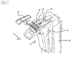
- the cylindrical body 32, the operation switch 36 and the stopper member 38 can be reversibly interposed between a locking position (as in FIG Fig. 4 shown) and a release position (as in Fig. 1 . 2 . 3 shown) are moved.
- the compression coil spring 37 serves to allow the cylindrical base body 32, the operation switch 36 and the stopper member 38 to automatically return to the release position without actuating the operation switch 36 from the locking position.
- the locking position serves to keep the pusher element 10 in the closed position. In the release position of the locking device 30, the pusher element 10 can return to the off position (see. Fig. 1 and 2 ).
- the counter stop element 40 essentially comprises a rectangular base body 42 with a top side 42a and a bottom side (not shown). At the top 42a is a cylindrical pin 44 is positioned with a tapered counter-abutment surface 44a. Counter-abutment surface 44a extends downwardly in direction N and thereby corresponds to abutment surface 39c of abutment element 38. Counter-abutment element 40 is positioned on top 12c of first portion 12 of L-shaped switching element 11, whereby counter-abutment element 40 relative to cylindrical body 32, the operation switch 36 and the stopper member 38 (as a result of the pivotal movement in the direction Q of the pusher member 10) can be moved.
- the unlocking switch 16 By pressing the unlocking switch 16, the blockage of the pusher member 10 is released and the pusher member 10 can be pivoted about the pivot axis R in the direction Q.
- the pusher element 10 can be held in the closed position with the aid of the locking device 30, without further pressure having to be exerted on the pusher element 10 by the user.
Abstract
Schaltervorrichtung zum Ein- und Ausschalten einer Werkzeugmaschine, enthaltend ein Drückerelement, welches reversibel um einen Schwenkpunkt zwischen einer Einschaltposition und einer Ausschaltposition schwenkbar ist, wobei in der Einschaltposition die Werkzeugmaschine eingeschaltet ist und in der Ausschaltposition die Werkzeugmaschine ausgeschaltet ist; und eine Arretiereinrichtung zum lösbaren Arretieren des Drückerelements in der Einschaltposition. Die Arretiereinrichtung enthält ein Anschlagelement und das Drückerelement enthält ein Gegenanschlagelement, wobei das Anschlagelement reversibel zwischen einer Arretierposition, in der das Anschlagelement an dem Gegenanschlagelement anliegt und das Drückerelement in der Einschaltposition gehalten ist, und einer Freigabeposition, in der das Drückerelement in die Ausschaltposition zurückkehrbar ist, bewegbar ist.

Description
Die vorliegende Erfindung betrifft eine Schaltervorrichtung zum Ein- und Ausschalten einer Werkzeugmaschine, enthaltend ein Drückerelement, welches reversibel um einen Schwenkpunkt zwischen einer Einschaltposition und einer Ausschaltposition schwenkbar ist, wobei in der Einschaltposition die Werkzeugmaschine eingeschaltet ist und in der Ausschaltposition die Werkzeugmaschine ausgeschaltet ist; und eine Arretiereinrichtung zum lösbaren Arretieren des Drückerelements in der Einschaltposition.The present invention relates to a switch device for turning on and off a machine tool, comprising a pusher element which is reversibly pivotable about a pivot point between a switch-on and a switch-off position, wherein in the switch-on position the machine tool is switched on and in the switch-off position the machine tool is switched off; and a locking means for releasably locking the pusher member in the on position.
Derartige Schaltervorrichtungen sind weitgehend bekannt und finden vor allem für eine elektrische Werkzeugmaschine mit einem Elektromotor, wie beispielsweise Bohrmaschinen, Schleifer, Sägen, Hobel, Winkelschleifer oder dergleichen, Verwendung. Bei der Werkzeugmaschine kann es sich um eine akku- und/oder netzbetriebene Werkzeugmaschine handeln.Such switch devices are widely known and find above all for an electrical machine tool with an electric motor, such as drills, grinders, saws, planer, angle grinder or the like, use. The machine tool can be a battery-powered and / or mains-operated machine tool.
Aus der
Darüber hinaus ist auch aus der
Die vorstehend beschriebenen Schaltervorrichtungen des Stands der Technik sind oftmals sehr komplex und raumgreifend ausgestaltet, so dass aus Platzgründen in der jeweiligen Schaltervorrichtung entweder nur eine Arretiereinrichtung, die das Schalterelement in einem Einschaltmodus hält, oder nur eine Transportsicherung, die bei einem Transport der Werkzeugmaschine das Schaltelement sperrt, verwirklicht werden kann. Eine Schaltervorrichtung, in der sowohl eine Arretiereinrichtung als auch eine Transportsicherung integriert werden kann, ist daher nur durch eine wesentliche Vergrößerung der gesamten Schaltervorrichtung möglich.The above-described switch devices of the prior art are often designed very complex and space-consuming, so that for reasons of space in the respective switch device, either only a locking device that holds the switch element in a power-on mode, or only a transport lock, which in a transport of the machine tool, the switching element locks, can be realized. A switch device in which both a locking device and a transport lock can be integrated, is therefore possible only by a substantial enlargement of the entire switch device.
Darüber hinaus besteht bei den Schaltervorrichtungen des Stands der Technik auch häufig das Problem, dass sich die Arretiereinrichtung bei starken Vibrationen, wie sie während des Gebrauchs der Werkzeugmaschine auftreten können, wieder lösen kann und die Werkzeugmaschine ungewollt wieder ausgeschaltet wird.In addition, the switch devices of the prior art also often have the problem that the locking device can again loosen under strong vibrations, such as may occur during use of the machine tool, and the machine tool is unintentionally switched off again.
Es ist daher Aufgabe der vorliegenden Erfindung eine verbesserte Schaltervorrichtung zum Ein- und Ausschalten einer Werkzeugmaschine zur Verfügung zu stellen, die die vorstehend beschriebenen Probleme beseitigt und insbesondere eine platzsparende sowie vibrationsresistente Arretiereinrichtung aufweist.It is therefore an object of the present invention to provide an improved switch device for switching on and off a machine tool, which eliminates the problems described above and in particular has a space-saving and vibration-resistant locking device.
Die Aufgabe wird erfindungsgemäss durch den Gegenstand des unabhängigen Anspruchs 1. Weitere vorteilhafte Ausgestaltungsformen der vorliegenden Erfindung sind in den entsprechenden Unteransprüchen enthalten.The object is achieved according to the invention by the subject matter of
Somit wird eine Schaltervorrichtung zum Ein- und Ausschalten einer Werkzeugmaschine, enthaltend ein Drückerelement, welches reversibel um einen Schwenkpunkt zwischen einer Einschaltposition und einer Ausschaltposition schwenkbar ist, wobei in der Einschaltposition die Werkzeugmaschine eingeschaltet ist und in der Ausschaltposition die Werkzeugmaschine ausgeschaltet ist; und eine Arretiereinrichtung zum lösbaren Arretieren des Drückerelements in der Einschaltposition zur Verfügung gestellt.Thus, a switch apparatus for turning on and off a machine tool including a pusher member reversibly pivotable about a pivot point between a switch-on position and a switch-off position, wherein in the switch-on position, the machine tool is turned on and in the switch-off position, the machine tool is turned off; and a locking means for releasably locking the pusher member in the on position provided.
Erfindungsgemäß ist vorgesehen, dass die Arretiereinrichtung ein Anschlagelement und das Drückerelement ein Gegenanschlagelement enthält, wobei das Anschlagelement reversibel zwischen einer Arretierposition, in der das Anschlagelement an dem Gegenanschlagelement anliegt und das Drückerelement in der Einschaltposition gehalten ist, und einer Freigabeposition, in der das Drückerelement in die Ausschaltposition zurückkehrbar ist, bewegbar ist. Hierdurch wird eine platzsparende Arretiereinrichtung verwirklicht, durch die in der Schaltervorrichtung noch genügend Platz für eine Transportsicherung lässt.According to the invention it is provided that the locking device comprises a stop element and the pusher element comprises a counter-stop element, wherein the stop element reversibly between a locking position, in which the stop element bears against the counter stop element and the pusher element is held in the on position, and a release position in which the pusher element in the switch-off position is traceable is movable. As a result, a space-saving locking device is realized by leaving enough space in the switch device for a transport lock.
Gemäss einer weiteren vorteilhaften Ausgestaltungsform der vorliegenden Erfindung kann vorgesehen sein, dass das Anschlagelement eine abgeschrägte Anschlagsfläche und das Gegenanschlagelement eine zu der abgeschrägten Anschlagsfläche korrespondierenden Gegenanschlagsfläche aufweist. Durch die Anschlagsfläche und die hierzu korrespondierende Gegenanschlagsfläche kann ein Lösen der Arretiereinrichtung aufgrund von hohen Vibrationen während des Gebrauchs der Werkzeugmaschine effektiv verhindert werden.According to a further advantageous embodiment of the present invention, it can be provided that the stop element has a beveled abutment surface and the counter stop element has a counterstop surface which corresponds to the bevelled abutment surface. By the abutment surface and the counter stop surface corresponding thereto, a release of the locking device due to high vibrations during use of the machine tool can be effectively prevented.
Die Erfindung wird bezüglich vorteilhafter Ausführungsbeispiele näher erläutert, hierbei zeigt
- Fig. 1
- eine Seitenansicht einer Werkzeugmaschine mit einer erfindungsgemässen Messvorrichtung zum Erfassen der Laufzeit einer Werkzeugmaschine; und
- Fig. 2
- einen Schaltplan für die erfindungsgemässe Messvorrichtung
- Fig. 3
- einen Schaltplan für die erfindungsgemässe Messvorrichtung
- Fig. 4
- einen Schaltplan für die erfindungsgemässe Messvorrichtung; und
- Fig. 5
- einen Schaltplan für die erfindungsgemässe Messvorrichtung.
- Fig. 1
- a side view of a machine tool with an inventive measuring device for detecting the running time of a machine tool; and
- Fig. 2
- a circuit diagram for the inventive measuring device
- Fig. 3
- a circuit diagram for the inventive measuring device
- Fig. 4
- a circuit diagram for the inventive measuring device; and
- Fig. 5
- a circuit diagram for the inventive measuring device.
Die Schaltervorrichtung 1 enthält im Wesentlichen ein Drückerelement 10, Schaltergehäuse 20 sowie eine Arretiereinrichtung 30.The
Das Drückerelement 10 enthält wiederum ein L-förmiges Schaltelement 11, eine Druckfeder 15 und einen Entriegelungsschalter 16. Das L-förmige Schaltelement 11 besteht aus einem ersten (kurzen) Anteil 12 und einen zweiten (langen) Anteil 14.The
Der erste Anteil 12 enthält ein erstes Ende 12a, ein zweites Ende 12b, eine erste Oberfläche 12c und eine zweite Oberfläche 12d. Der zweite Anteil 14 enthält ebenfalls ein erstes Ende 14a, ein zweites Ende 14b, eine erste Oberfläche 14c und eine zweite Oberfläche 14d. Die erste Oberfläche 14c des zweiten Anteils 14 dient insbesondere Auflagefläche für die (nicht gezeigten) Finger eines Anwenders, der das Drückerelement 10 zum Einschalten der Werkzeugmaschine drücken möchte. Die zweite Oberfläche 14d des zweiten Anteils 14 enthält ein (nicht gezeigtes) Kontaktelement, mit dem ein Gegenkontaktelement 13 an dem Schaltergehäuse 20 betätigt werden kann, wenn das Drückerelement 10 relativ zu dem Schaltergehäuse 20 geschwenkt wird. Das zweite Ende 12b des ersten Anteils 12 ist fest mit dem ersten Ende 14a des zweiten Anteils 14 verbunden. Das zweite Ende 14b des zweiten Anteils 14 enthält einen Schenkpunkt S auf der Schwenkachse R um den das Schaltelement 11 geschwenkt werden kann (vgl.
Wie in
Der Entriegelungsschalter 16 dient als Transportsicherung und verhindert, wenn dieser nicht gedrückt wird, dass das Drückerelement 10 geschwenkt und die Werkzeugmaschine gestartet werden kann. Der Entriegelungsschalter 16 befindet sich schwenkbar gelagert an der ersten Oberfläche 14c des zweiten Anteils 14 zwischen dem ersten Anteil 12 und dem zweiten Anteil 14 des Schaltelements 11.
Die Arretiereinrichtung 30 enthält im Wesentlichen einen zylindrischen Grundkörper 32, einen Betätigungsschalter 36, ein Anschlagelement 38 und ein Gegenanschlagelement 40.The locking
Wie in
Das Anschlagelement 38 enthält einen länglichen Grundkörper 39 mit einem ersten Ende 39a und einem zweiten Ende 39b. Das Anschlagelement 38 ist mit dem ersten Ende 39a des länglichen Grundkörpers 39 so an der Mantelfläche des zylindrischen Grundkörper 32 ist das Anschlagelement 38 positioniert, dass sich dieses in einem rechten Winkel (in Richtung P erstreckt) zu dem zylindrischen Grundkörper 32 erstreckt. An dem zweiten (freien) Ende 39b des länglichen Grundkörpers 39 befindet sich eine abgeschrägte, d.h. in Richtung N ansteigende Anschlagsfläche 39c.The
Der zylindrische Grundkörper 32, der Betätigungsschalter 36 sowie das Anschlagelement 38 sind an einem (nicht gezeigten) Gehäuse der (ebenfalls nicht gezeigten) Werkzeugmaschine befestigt. Das Drückerelement 10 kann somit relativ zu dem zylindrischen Grundkörper 32, dem Betätigungsschalter 36 und insbesondere zu dem Anschlagelement 38 geschwenkt werden. Darüber hinaus können der zylindrische Grundkörper 32, der Betätigungsschalter 36 und das Anschlagelement 38 reversibel zwischen einer Arretierposition (wie in
Das Gegenanschlagelement 40 enthält im Wesentlichen einen rechteckigen Grundkörper 42 mit einer Oberseite 42a und einer (nicht gezeigten) Unterseite. An der Oberseite 42a ist ein zylindrischer Stift 44 mit einer abgeschrägten Gegenanschlagsfläche 44a positioniert. Die Gegenanschlagsfläche 44a verläuft in Richtung N abfallend und korrespondiert dadurch zu der Anschlagsfläche 39c des Anschlagelements 38. Das Gegenanschlagelement 40 ist an der Oberseite 12c des ersten Anteils 12 des L-förmigen Schaltelements 11 positioniert, wodurch das Gegenanschlagelement 40 relativ zu dem zylindrischen Grundkörper 32, dem Betätigungsschalter 36 und zu dem Anschlagelement 38 (in Folge der Schwenkbewegung in Richtung Q des Drückerelements 10) bewegt werden kann.The
Durch Drücken des Entriegelungsschalters 16 wird die Blockade des Drückerelements 10 aufgehoben und das Drückerelement 10 kann um die Schwenkachse R in Richtung Q geschwenkt werden.By pressing the unlocking
Durch Schwenken des Drückerelements 10 wird auch das Schaltelement 11 bewegt, so dass dieses von der Ausschaltstellung in die Einschaltstellung und damit relativ zu dem Schaltergehäuse 20 in Richtung P bewegt wird. Da das Gegenanschlagelement 40 fest mit dem ersten Anteil 12 des Schaltelements 11 verbunden ist, wird dieses mit dem Drückerelement 10 ebenfalls in die Einschaltstellung und damit in Richtung P bewegt (vgl.
Das Drückerelement 10 kann mit Hilfe der Arretiereinrichtung 30 in der Einschaltstellung gehalten werden, ohne dass weiterhin Druck von dem Anwender auf das Drückerelement 10 ausgeübt werden muss.The
Hierzu wird Druck auf den Betätigungsschalter 36 ausgeübt, so dass dieser in Richtung N und gegen die Druckschraubenfeder 37 bewegt wird. Der zylindrische Grundkörper 32, der Betätigungsschalter 36 und das Anschlagelement 38 bewegen sich in Richtung N in die Arretierposition. Um das Drückerelement 10 schließlich in der Einschaltstellung zu halten, werden die Gegenanschlagsfläche 44a des Gegenanschlagelements 40 und die Anschlagfläche 39c des Anschlagelements 38 gegen den Druck der Druckfeder 15 aufeinander gedrückt. Dadurch, dass die Druckfeder 15 wesentlich stärker ist als die Druckschraubenfeder 37 sowie insbesondere durch die abgeschrägte Anschlagsfläche 39c und die dazu korrespondierende Gegenanschlagsfläche 44a bleiben die Anschlagsfläche 39c und die Gegenanschlagsfläche 44a in Kontakt zueinander (vgl.
Um die Arretierung, d.h. die feste Einstellung des Drückerelements 10 wieder aufzuheben und so das Drückerelement 10 von der (blockierten) Einschaltstellung wieder zurück in die Ausschaltstellung bewegen zu können. Wird zunächst Druck auf das Schaltelement 11 ausgeübt, um damit das Drückerelement 10 in Richtung P zu bewegen. Aufgrund dieser Bewegung in Richtung P werden die Anschlagsfläche 39c und hierzu die korrespondierende Gegenanschlagsfläche 44a wieder auseinander bewegt, so dass ein gewisser Spalt zwischen den beiden Flächen 39c, 44a entsteht. Sobald der Spalt zwischen den beiden Flächen 39c, 44a entsteht, bewegt sich der zylindrische Grundkörper 32, der Betätigungsschalter 36, das Anschlagelement 38 durch den Druck der Druckschraubenfeder 37 in dem zylindrischen Grundkörper 32 von der Arretierposition (wie in
Claims (2)
dadurch gekennzeichnet, dass das Anschlagelement (38) eine abgeschrägte Anschlagsfläche (39c) und das Gegenanschlagelement (40) eine zu der abgeschrägten Anschlagsfläche (39c) korrespondierenden Gegenanschlagsfläche (44a) aufweist.Switching device (1) according to claim 1,
characterized in that the stop element (38) has a beveled abutment surface (39c) and the counter-abutment element (40) has a counterstop surface (44a) corresponding to the beveled abutment surface (39c).
Priority Applications (5)
| Application Number | Priority Date | Filing Date | Title |
|---|---|---|---|
| EP13197454.5A EP2884515A1 (en) | 2013-12-16 | 2013-12-16 | Device switch for electric tools with a locking switch |
| EP14816204.3A EP3084788A1 (en) | 2013-12-16 | 2014-12-12 | Appliance switch for electric tools having switch locking |
| US15/104,497 US20160322183A1 (en) | 2013-12-16 | 2014-12-12 | Device switch for power tools including a switch locking mechanism |
| JP2016539995A JP2017501039A (en) | 2013-12-16 | 2014-12-12 | Switch device for electric tools with switch locking |
| PCT/EP2014/077537 WO2015091255A1 (en) | 2013-12-16 | 2014-12-12 | Appliance switch for electric tools having switch locking |
Applications Claiming Priority (1)
| Application Number | Priority Date | Filing Date | Title |
|---|---|---|---|
| EP13197454.5A EP2884515A1 (en) | 2013-12-16 | 2013-12-16 | Device switch for electric tools with a locking switch |
Publications (1)
| Publication Number | Publication Date |
|---|---|
| EP2884515A1 true EP2884515A1 (en) | 2015-06-17 |
Family
ID=49876380
Family Applications (2)
| Application Number | Title | Priority Date | Filing Date |
|---|---|---|---|
| EP13197454.5A Withdrawn EP2884515A1 (en) | 2013-12-16 | 2013-12-16 | Device switch for electric tools with a locking switch |
| EP14816204.3A Withdrawn EP3084788A1 (en) | 2013-12-16 | 2014-12-12 | Appliance switch for electric tools having switch locking |
Family Applications After (1)
| Application Number | Title | Priority Date | Filing Date |
|---|---|---|---|
| EP14816204.3A Withdrawn EP3084788A1 (en) | 2013-12-16 | 2014-12-12 | Appliance switch for electric tools having switch locking |
Country Status (4)
| Country | Link |
|---|---|
| US (1) | US20160322183A1 (en) |
| EP (2) | EP2884515A1 (en) |
| JP (1) | JP2017501039A (en) |
| WO (1) | WO2015091255A1 (en) |
Cited By (4)
| Publication number | Priority date | Publication date | Assignee | Title |
|---|---|---|---|---|
| EP3217412A1 (en) * | 2016-03-08 | 2017-09-13 | Festool GmbH | Switch for a hand-held power tool |
| WO2021063553A1 (en) * | 2019-10-01 | 2021-04-08 | Steinel Gmbh | Electrical, pistol-like handheld tool |
| US11867224B2 (en) | 2021-01-27 | 2024-01-09 | Black & Decker Inc. | Locking mechanism for two telescoping poles of a power tool |
| US11931851B2 (en) | 2019-10-23 | 2024-03-19 | Black & Decker Inc. | Pole sander |
Families Citing this family (5)
| Publication number | Priority date | Publication date | Assignee | Title |
|---|---|---|---|---|
| EP3503145B1 (en) * | 2017-12-22 | 2023-04-19 | Defond Electech Co., Ltd | A locking system for use with a trigger assembly of an electrical device |
| CN110480581A (en) * | 2018-05-14 | 2019-11-22 | 株式会社牧田 | Percussion tool |
| CN111710545A (en) | 2020-07-20 | 2020-09-25 | 格力博(江苏)股份有限公司 | Switch assembly, switch assembly starting method and electric tool |
| CN112038137A (en) * | 2020-09-23 | 2020-12-04 | 格力博(江苏)股份有限公司 | Switch assembly and electric tool |
| TWI745198B (en) * | 2020-12-21 | 2021-11-01 | 力山工業股份有限公司 | Foldable miter saw with safety device |
Citations (10)
| Publication number | Priority date | Publication date | Assignee | Title |
|---|---|---|---|---|
| DE1120543B (en) * | 1960-03-30 | 1961-12-28 | Bosch Gmbh Robert | Actuating device for electrical built-in device switch with latching lever |
| DE2254554A1 (en) * | 1972-11-08 | 1974-05-09 | Licentia Gmbh | SWITCH FOR AN ELECTRIC MOTOR DRIVEN MACHINE TOOL |
| DE2410871A1 (en) | 1974-03-07 | 1975-09-18 | Marquardt J & J | ELECTRIC SWITCH WITH LOCKING DEVICE |
| US3953696A (en) * | 1973-07-14 | 1976-04-27 | J. & J. Marquardt | Actuator construction having releasable lock in actuated and deactuated positions |
| US4879438A (en) * | 1988-08-01 | 1989-11-07 | Ryobi Motor Products Corp. | Lock-on/lock-off switch for power tool |
| DE19745100A1 (en) * | 1996-10-22 | 1998-04-23 | Marquardt Gmbh | Electric switch with housing, locating manual, changeover actuator |
| DE19962002A1 (en) * | 1999-12-22 | 2001-06-28 | Marquardt Gmbh | Electric switch with lock-out device for preventing starting or closure of machine, such as hand drill or cutter, has actuating element designed as slide/slide valve with movable cam element |
| EP1174892A2 (en) * | 2000-07-17 | 2002-01-23 | Heinrich Kopp AG | Mechanical locking device for on- and off-position of an electrical push switch |
| DE102006028637A1 (en) * | 2006-06-22 | 2007-12-27 | Robert Bosch Gmbh | Electric switch with a locking element |
| EP2101340A1 (en) | 2008-03-12 | 2009-09-16 | Marquardt GmbH | Electric switch, in particular electric tool switch |
Family Cites Families (9)
| Publication number | Priority date | Publication date | Assignee | Title |
|---|---|---|---|---|
| US3847233A (en) * | 1973-06-29 | 1974-11-12 | Black & Decker Mfg Co | Trigger mechanism for hand-operated power device providing automatic lock-off and manual lock-on operation |
| US3873796A (en) * | 1973-07-06 | 1975-03-25 | Black & Decker Mfg Co | Trigger mechanism for hand-operated power device including independently operable locking devices providing automatic lock off and manual lock-on operation |
| JPS5634340Y2 (en) * | 1975-01-13 | 1981-08-14 | ||
| JP3307195B2 (en) * | 1995-10-13 | 2002-07-24 | 住友電装株式会社 | Breaker device |
| US5638945A (en) * | 1996-06-10 | 1997-06-17 | Ryobi North America, Inc. | Locking trigger mechanism for a portable power tool |
| US6469269B1 (en) * | 2001-04-02 | 2002-10-22 | Jenn Feng Industrial Co., Ltd. | Two-stage self-locking switch structure for hand tools |
| DE60305539T2 (en) * | 2002-01-10 | 2007-05-03 | Black & Decker Inc., Newark | gearbox |
| US6812425B1 (en) * | 2003-11-24 | 2004-11-02 | Defond Components Limited | Locking trigger switch mechanism |
| JP5068064B2 (en) * | 2006-11-08 | 2012-11-07 | 株式会社マキタ | Impact tool |
-
2013
- 2013-12-16 EP EP13197454.5A patent/EP2884515A1/en not_active Withdrawn
-
2014
- 2014-12-12 JP JP2016539995A patent/JP2017501039A/en active Pending
- 2014-12-12 US US15/104,497 patent/US20160322183A1/en not_active Abandoned
- 2014-12-12 EP EP14816204.3A patent/EP3084788A1/en not_active Withdrawn
- 2014-12-12 WO PCT/EP2014/077537 patent/WO2015091255A1/en active Application Filing
Patent Citations (10)
| Publication number | Priority date | Publication date | Assignee | Title |
|---|---|---|---|---|
| DE1120543B (en) * | 1960-03-30 | 1961-12-28 | Bosch Gmbh Robert | Actuating device for electrical built-in device switch with latching lever |
| DE2254554A1 (en) * | 1972-11-08 | 1974-05-09 | Licentia Gmbh | SWITCH FOR AN ELECTRIC MOTOR DRIVEN MACHINE TOOL |
| US3953696A (en) * | 1973-07-14 | 1976-04-27 | J. & J. Marquardt | Actuator construction having releasable lock in actuated and deactuated positions |
| DE2410871A1 (en) | 1974-03-07 | 1975-09-18 | Marquardt J & J | ELECTRIC SWITCH WITH LOCKING DEVICE |
| US4879438A (en) * | 1988-08-01 | 1989-11-07 | Ryobi Motor Products Corp. | Lock-on/lock-off switch for power tool |
| DE19745100A1 (en) * | 1996-10-22 | 1998-04-23 | Marquardt Gmbh | Electric switch with housing, locating manual, changeover actuator |
| DE19962002A1 (en) * | 1999-12-22 | 2001-06-28 | Marquardt Gmbh | Electric switch with lock-out device for preventing starting or closure of machine, such as hand drill or cutter, has actuating element designed as slide/slide valve with movable cam element |
| EP1174892A2 (en) * | 2000-07-17 | 2002-01-23 | Heinrich Kopp AG | Mechanical locking device for on- and off-position of an electrical push switch |
| DE102006028637A1 (en) * | 2006-06-22 | 2007-12-27 | Robert Bosch Gmbh | Electric switch with a locking element |
| EP2101340A1 (en) | 2008-03-12 | 2009-09-16 | Marquardt GmbH | Electric switch, in particular electric tool switch |
Cited By (4)
| Publication number | Priority date | Publication date | Assignee | Title |
|---|---|---|---|---|
| EP3217412A1 (en) * | 2016-03-08 | 2017-09-13 | Festool GmbH | Switch for a hand-held power tool |
| WO2021063553A1 (en) * | 2019-10-01 | 2021-04-08 | Steinel Gmbh | Electrical, pistol-like handheld tool |
| US11931851B2 (en) | 2019-10-23 | 2024-03-19 | Black & Decker Inc. | Pole sander |
| US11867224B2 (en) | 2021-01-27 | 2024-01-09 | Black & Decker Inc. | Locking mechanism for two telescoping poles of a power tool |
Also Published As
| Publication number | Publication date |
|---|---|
| EP3084788A1 (en) | 2016-10-26 |
| US20160322183A1 (en) | 2016-11-03 |
| JP2017501039A (en) | 2017-01-12 |
| WO2015091255A1 (en) | 2015-06-25 |
Similar Documents
| Publication | Publication Date | Title |
|---|---|---|
| EP2884515A1 (en) | Device switch for electric tools with a locking switch | |
| DE2335972C3 (en) | Switches, in particular for an electric hand tool | |
| EP2107650B1 (en) | Press clamp with a positioning device | |
| EP3030385B1 (en) | Knife | |
| DE102007050683B4 (en) | Conductor terminal | |
| AT393089B (en) | SKI BINDING | |
| EP2242082B1 (en) | Holder for fuses | |
| DE202010008031U1 (en) | Locking switch device for a power tool | |
| DE1615840A1 (en) | Adjustable squeezing tool | |
| EP1539391A1 (en) | Bending tool and tool holding fixture therefor | |
| DE102004040288A1 (en) | Circuit breaker with short-circuit and overload trip indication and corresponding procedure | |
| EP3224001B1 (en) | Self-locking latch of an adapter device | |
| EP3411547B1 (en) | Casement fastener lock with adjustable position of a locking element on locking shaft | |
| EP3184706B1 (en) | Holding device with a holding slider sliding along a holding bar | |
| EP0585541B1 (en) | Electric switch for speed control of motors | |
| EP2186579A2 (en) | Bending tool and tool holder for a bending machine | |
| EP1679466B1 (en) | Universal support | |
| EP0274746A1 (en) | Clamp with adjustable jaws | |
| EP1862241B1 (en) | Powered Chuck | |
| DE2047758C3 (en) | Actuating device, in particular for an electrical switch, with an actuating member that can be locked by a latching device | |
| EP3318375A1 (en) | Machine tool with adjustable stop device | |
| EP3524393B1 (en) | Device for locking a battery pack | |
| DE102016103868B3 (en) | The jaw assembly | |
| DE102014115060B4 (en) | connecting device | |
| WO2020099633A1 (en) | Bipolar sealing instrument with partly automated actuating mechanism |
Legal Events
| Date | Code | Title | Description |
|---|---|---|---|
| PUAI | Public reference made under article 153(3) epc to a published international application that has entered the european phase |
Free format text: ORIGINAL CODE: 0009012 |
|
| 17P | Request for examination filed |
Effective date: 20131216 |
|
| AK | Designated contracting states |
Kind code of ref document: A1 Designated state(s): AL AT BE BG CH CY CZ DE DK EE ES FI FR GB GR HR HU IE IS IT LI LT LU LV MC MK MT NL NO PL PT RO RS SE SI SK SM TR |
|
| AX | Request for extension of the european patent |
Extension state: BA ME |
|
| STAA | Information on the status of an ep patent application or granted ep patent |
Free format text: STATUS: THE APPLICATION IS DEEMED TO BE WITHDRAWN |
|
| 18D | Application deemed to be withdrawn |
Effective date: 20151218 |