EP2186579A2 - Bending tool and tool holder for a bending machine - Google Patents
Bending tool and tool holder for a bending machine Download PDFInfo
- Publication number
- EP2186579A2 EP2186579A2 EP09013145A EP09013145A EP2186579A2 EP 2186579 A2 EP2186579 A2 EP 2186579A2 EP 09013145 A EP09013145 A EP 09013145A EP 09013145 A EP09013145 A EP 09013145A EP 2186579 A2 EP2186579 A2 EP 2186579A2
- Authority
- EP
- European Patent Office
- Prior art keywords
- contact
- tool
- bending
- bending tool
- tool holder
- Prior art date
- Legal status (The legal status is an assumption and is not a legal conclusion. Google has not performed a legal analysis and makes no representation as to the accuracy of the status listed.)
- Granted
Links
- 238000005452 bending Methods 0.000 title claims abstract description 138
- 230000008878 coupling Effects 0.000 claims abstract description 7
- 238000010168 coupling process Methods 0.000 claims abstract description 7
- 238000005859 coupling reaction Methods 0.000 claims abstract description 7
- 238000000034 method Methods 0.000 claims abstract description 6
- 230000005540 biological transmission Effects 0.000 claims description 22
- 238000003825 pressing Methods 0.000 claims description 3
- 230000000284 resting effect Effects 0.000 abstract 2
- 230000006835 compression Effects 0.000 description 12
- 238000007906 compression Methods 0.000 description 12
- 238000003780 insertion Methods 0.000 description 6
- 230000037431 insertion Effects 0.000 description 6
- 239000004020 conductor Substances 0.000 description 5
- 238000004519 manufacturing process Methods 0.000 description 3
- 239000002184 metal Substances 0.000 description 3
- 229910052751 metal Inorganic materials 0.000 description 3
- 238000012546 transfer Methods 0.000 description 3
- 230000004913 activation Effects 0.000 description 2
- 238000010276 construction Methods 0.000 description 2
- 230000006870 function Effects 0.000 description 2
- 238000000926 separation method Methods 0.000 description 2
- 230000009471 action Effects 0.000 description 1
- 238000011109 contamination Methods 0.000 description 1
- 230000009849 deactivation Effects 0.000 description 1
- 230000000994 depressogenic effect Effects 0.000 description 1
- 238000011161 development Methods 0.000 description 1
- 238000005553 drilling Methods 0.000 description 1
- 230000000694 effects Effects 0.000 description 1
- 239000013536 elastomeric material Substances 0.000 description 1
- 239000012777 electrically insulating material Substances 0.000 description 1
- 239000010931 gold Substances 0.000 description 1
- 229910052737 gold Inorganic materials 0.000 description 1
- 238000009413 insulation Methods 0.000 description 1
- 238000003754 machining Methods 0.000 description 1
- 239000000463 material Substances 0.000 description 1
- 238000005259 measurement Methods 0.000 description 1
- 150000002739 metals Chemical class 0.000 description 1
- 229920003023 plastic Polymers 0.000 description 1
- 239000004033 plastic Substances 0.000 description 1
- 230000008569 process Effects 0.000 description 1
- 230000007704 transition Effects 0.000 description 1
Images

Classifications
-
- B—PERFORMING OPERATIONS; TRANSPORTING
- B21—MECHANICAL METAL-WORKING WITHOUT ESSENTIALLY REMOVING MATERIAL; PUNCHING METAL
- B21D—WORKING OR PROCESSING OF SHEET METAL OR METAL TUBES, RODS OR PROFILES WITHOUT ESSENTIALLY REMOVING MATERIAL; PUNCHING METAL
- B21D5/00—Bending sheet metal along straight lines, e.g. to form simple curves
- B21D5/02—Bending sheet metal along straight lines, e.g. to form simple curves on press brakes without making use of clamping means
- B21D5/0209—Tools therefor
- B21D5/0254—Tool exchanging
Definitions
- the invention relates to a bending tool according to the preamble of patent claim 1 and a tool holder according to the preamble of claim 15, further a bending machine according to the preamble of claim 19 and a method for electrical coupling of a bending tool with a tool holder according to the preamble of claim 20.
- press brakes can be used in the tool holders for upper tool or lower tool depending on the workpieces to be bent a variety of tools.
- the bending machines are equipped with programmable electronic control devices, which allow the execution of exact and optimized bending operations based on information about the workpiece to be bent and information about the respective bending tools used.
- Bending tools are already known for this purpose, which can be identified by the control device on the basis of information transmitted by the bending tool to the control device, or on which measuring elements, in particular electrical measuring sensors are arranged or integrated and thereby measured values, in particular information, during a bending operation can be transmitted to the control device via the bending process or the workpiece to be bent.
- This transfer takes place in many cases via electrical contacts which form an electrical interface between the bending tool and tool holder, wherein in the inserted state of the bending tools contacts are brought to a mounting portion of a bending tool with contacts on a receiving portion of the tool holder in touching electrical connection, whereby a functional element the bending tool, for example, an information carrier or a measuring element with a control device of the bending machine can be brought into connection.
- Currents flowing through such an electrical interface between the bending tool and the tool holder can serve both to supply energy to a functional element in the bending tool and to transfer data between the functional element and the control device.
- a disadvantage of this type of contact is that the contact pins protrude from the bending tool not used in the tool holder and therefore often mechanical stresses can be exposed, which can cause damage to the pins or the contact pin guides and the resilient mounting. Furthermore, when the bending tool is not approached in the direction of the contact pins on the tool holder, grinding operations between the contact pins and the tool holder take place, which cause wear of the contacting surfaces and therefore the electrical connection between the bending tool and tool holder is not ensured in the long run.
- the object of the invention is an interface for the electrical connection of a. Functional element to provide a bending tool with a contact surface on a tool holder of a bending machine, which permanently has a high reliability.
- a bending tool with the features of claim 1, according to which the bending tool comprises a coupling with a receiving portion of the tool holder mounting portion and an adjustably mounted contact element for electrically connecting a formed on the bending tool function element with a contact surface on the receiving portion of the tool holder, and in this case, the contact element can be moved outward by a contact element arranged on the receiving portion of the tool holder from a contact surface spaced rest position relative to an outer surface of the mounting portion in a contact surface contacting the contact position.
- the contact element for example, in the form of a contact pin, is therefore not as in the prior art by a contact surface on the tool holder from a rest position to pressed inside the contact position, but actively spent by a separate actuator on the tool holder from a rest position to the outside in a contact surface contacting contact position.
- a cooperating with the bending tool according to the invention inventive tool holder on a bending machine has according to claim 15 a receiving portion for coupling a mounting portion of a bending tool and an electrically conductive, connected to a power supply device or a control device contact surface on the receiving portion, wherein for an adjustment on the attachment portion of the bending tool between a rest position and a contact position adjustably mountedschreiblements on the receiving portion of the tool holder is an adjustably mounted, connected to an adjustment and the contact element in the contact position-bringing actuator is arranged.
- the object of the invention is further achieved by a method for electrically coupling a functional element on a bending tool with a contact surface on a tool holder by means of a bending tool adjustably mounted contact element, according to the invention in a first step, the bending tool is moved to its intended position on the tool holder and In a subsequent second step, the contact element is adjusted by means of an actuator formed on the tool holder from a distance to the contact surface rest position in a contact surface contacting the contact position.
- the actuator on the tool holder can act directly on the contact element mechanically, but it is also possible that a movement of the actuator is transmitted by means of an adjustable mounting portion on the transfer element mounted on the contact element, for example.
- a pressure piece or a pivot lever or the like can act directly on the contact element mechanically, but it is also possible that a movement of the actuator is transmitted by means of an adjustable mounting portion on the transfer element mounted on the contact element, for example.
- a pressure piece or a pivot lever or the like can act directly on the contact element mechanically, but it is also possible that a movement of the actuator is transmitted by means of an adjustable mounting portion on the transfer element mounted on the contact element, for example.
- a pressure piece or a pivot lever or the like can act directly on the contact element mechanically, but it is also possible that a movement of the actuator is transmitted by means of an adjustable mounting portion on the transfer element mounted on the contact element, for example.
- a pressure piece or a pivot lever or the like can act directly on the contact element mechanically, but it is also possible that a movement
- the at least one contact element if it is not actively spent by the actuator in the contact position, automatically assumes the rest position in which it has a distance to the contact surface of the tool holder or set back relative to the outer surface of the mounting portion, it is advantageous if in Attachment section is arranged on the contact element or the transmission element in the direction of the rest position acting spring element. Characterized the contact element is automatically spent after deactivation of the actuator of the tool holder by the spring element in the protected rest position.
- the contact element can thereby be guided approximately rectilinearly in the attachment section, whereby a gentle touching of the contact surface is ensured, in particular if the guide direction is oriented at right angles to the contact surface. Furthermore, a straight-line guide of the contact element may be advantageous if the actuating member and the contact surface are arranged approximately diametrically with respect to the fastening portion located therebetween on the tool holder.
- the contact element may be guided by means of a pivot bearing in the attachment portion, such as when the actuator and the contact surface on the tool holder are not diametrically opposed to each other and the adjustment of the actuator to the adjustment of the contact element forms an angle.
- the contact element may be designed for reasons of ease of manufacture as a cylindrical contact pin or pin.
- the spring element can be designed as a force acting on the contact element or the transmission element, in particular already biased in the rest position compression spring.
- This embodiment is useful when the contact element is designed as a rectilinear guided, cylindrical contact pin, wherein the compression spring can comprise the contact pin concentrically and is supported on a pinhole, which is mounted on the outer surface of the mounting portion.
- the flow of current to or from the functional element takes place in the simplest case on the one hand via the generally metallic bending tool that touches the metallic tool holder and on the other hand via the opposite electrically conductive contact element to the rest of the bending tool, but it can also be provided for the functional element two own, to each other and to provide the bending tool galvanically isolated contact elements. Furthermore, it is possible that a plurality of functional elements are arranged in a bending tool, which is why it may be advantageous if the actuating member acts on at least two contact elements or two transmission elements.
- the bending tool may also have a transmission element which acts on at least two contact elements. Due to these two Ausrrittungs. despite multiple contact elements can be dispensed with the use of multiple actuators or several transmission elements, resulting in structurally simple solutions.
- the guide sleeve can be formed in particular from a material selected from a group comprising metals and plastics with a low coefficient of sliding friction.
- an elastic connecting element is arranged between the contact element and the transmission element.
- the elastic connecting element can in turn be designed as a spring element, for example, as a compression spring or tension spring made of a metal or else be formed by a connecting element made of elastomeric material.
- it can be formed on the contact element itself or on the transmission element itself an elastically deformable portion that makes its own additional connection element dispensable by at least one of the two parts can deform so far that extreme contact forces are avoided when the adjustment of the actuator by a fixed Stop element is limited.
- the contact element has a hard-gold-plated surface at least in a contact section which possibly makes contact with the contact surface and which is additionally wear-resistant.
- the functional element can be formed on the bending tool by a measuring element, in particular an electrical measuring transducer, whereby, before, during or after machining and / or reshaping existing properties of the workpiece, such as mechanical variables detected and supplied to the control device of the bending machine can be.
- a measuring element in particular an electrical measuring transducer
- the measuring element can be designed in particular for detecting a geometric size of a workpiece to be machined with the bending tool, for example a bending angle on the workpiece in the loaded and / or unloaded state or, for example, the thickness of the workpiece before the bending deformation.
- the functional element can comprise a memory element, in particular for storing tool data, whereby the control device can be transferred either directly from the memory element parameters of the bending tool or after an identification of the bending tool used can be read in a memory stored outside the bending tool tool parameters.
- a simple construction of the tool holder can be achieved if the actuating member is formed by a fastening element fixing the fixing portion on the receiving portion.
- Such clamping elements are available in any case for the fixation of upper tools on the tool holder of an upper press beam anyway and can thereby be used simultaneously as an actuator for the contact element.
- the clamping element can be designed in particular as a wedge element, which cooperates with a keyway on the attachment portion of the bending tool. By acting between wedge element and keyway clamping forces can be a very stable and precise fixation of the bending tool on the tool holder and at the same time is one in the keyway arranged on the attachment portion actuator during handling outside the tool holder from damage well protected.
- the receiving portion of the tool holder comprises in an advantageous development of the invention, a tool holder groove in which the actuator and the contact surface can be arranged and are thus well protected from damage.
- the tool receiving groove extends in particular in the longitudinal direction of a press beam or a press table, whereby the position of the bending tool along the press beam or the press table can be chosen freely.
- the contact surface has, at least in sections, a hard-gold plated surface.
- the contact surface is formed on a contact rail extending in a longitudinal direction of the receiving portion and arranged in particular in a tool receiving groove.
- a plurality of mutually parallel contact rails may be formed.
- the contact surface may be formed by at least one conductor track mounted on an electrically insulating carrier element.
- the adjusting drive for the adjustment of the actuating member on the tool holder can be formed by a fluidically or electrically operated actuator.
- Fig. 1 shows a bending tool 1 during insertion into a tool holder 2 of a bending machine, not shown, in particular a press brake.
- the tool holder 2 is arranged on a press bar 3 shown in sections and has a flat receiving portion 4, to which a flat mounting portion 5 of the bending tool 1 can be coupled.
- the receiving portion 4 has a tool receiving groove 6, which is suitable for receiving a fastening extension 7 formed on the bending tool 1 or its attachment portion 5. Its outer contour substantially corresponds to the inner contour of the tool receiving groove 6, wherein between the tool receiving groove 6 and fastening extension 7 a required for the insertion or removal of the bending tool 1 functional game is available.
- the bending tool 1 can also be referred to as an upper tool 8, for example in the form of a bending punch 9, which cooperates with a lower tool (not shown), for example in the form of a press die and for bending forming of workpieces that can be formed.
- a lower tool for example in the form of a press die and for bending forming of workpieces that can be formed.
- sheet metal blanks is used.
- the connecting line 12 leads to a arranged on the attachment portion 5 contact element 13, which with a contact surface 14 on the receiving portion 4 of the tool holder 2 in Contact can be brought. From this contact surface 14, which is arranged, for example, on the surface of a contact rail 15, which extends in the longitudinal direction of the tool holder groove 6, another also shown in phantom leads connecting line 16 to the power source or control device, not shown.
- the contact element 13 is formed in the illustrated embodiment as a cylindrical contact pin 17 whose current-carrying parts are electrically isolated from the rest of the bending tool 1 by means of an electrically insulating guide sleeve 18.
- the contact element 13 on the attachment portion 5 and the contact surface 14 on the receiving portion 4 are each arranged so that the contact element 13 and contact surface 14 with proper positioning of the bending tool 1 on the tool holder 2 opposite each other directly and in this positioning of the bending tool 1, an electrical connection between the Functional element 10 and the power source or the control device can be produced.
- the contact surface 14 is approximately flush with a side surface of the Malawifactnut 6 and the contact element 13 in the form of the contact pin 17 is approximately at right angles with respect.
- a center plane 19 of the tool holder groove 6 and the bending tool 1 oriented.
- a spherical cap-shaped contact portion 20 is formed, the surface of which can be brought in the use position of the bending tool 1 with the contact surface 14 into contact.
- the contact element 13 In the illustrated position of the bending tool 1, the contact element 13 is in a rest position 21, in which the contact portion 20 against an outer surface 22 of the attachment portion 5 springs back, so does not project towards the outer contour of the attachment extension 7.
- the contact element 13 In this rest position 21, the contact element 13 is thus protected inside the mounting portion 5 and here the attachment extension 7, whereby in the rest position 21 of the contact element 13 between a functional element 10 and a power source or a control device existing circuit is not closed.
- the contact element 13 in a contact surface 14 contacting the contact position 23 - in the illustrated embodiment to the right - adjusted.
- the contact element 13 is for this purpose in the attachment section. 5 or adjustably mounted in the attachment extension 7, as here in the guide sleeve 18, wherein the adjustment from the rest position 21, according to Fig. 1 , in the contact position 23, according to Fig. 2 ,
- the actuator 24 here, for example, in the form of a pressure pin 25, is drivingly connected to an adjusting drive 26, whereby the contact element 13 can be actively adjusted from the rest position 21 into the contact position 23.
- Fig. 3 shows in detail again the contact zone between the contact element 13 and the contact surface 14.
- rest position 21 of the contact element 13 whose contact portion 20 has a distance 27 to the fixed contact surface 14, whereby in the rest position 21 between a functional element 10 and power supply source or control device trained circuit is not closed.
- the contact element 13 is moved in the adjustment direction 28 to the right by means of the actuator 24 on the receiving portion 4, whereby the contact section 20 contacts the contact surface 14 and the circuit between the functional element 10 and the power supply source or control device is closed at least at the interface between the bending tool 1 and the tool holder 2. While only one contact element 13 is shown in the figures, of course, several contact elements 13, 13 ', ... can be brought into electrical connection with one or more contact surfaces 14, 14', ... at the same time.
- the spring element 29 may be formed as a contact pin 17 concentrically comprising compression spring 30.
- the contact surface 14 can be formed approximately by a conductor 32 arranged on a carrier element 31.
- the carrier element 31 and the conductor track 32 are thus part of the contact rail 15 and the contact surface 14 or the conductor track 32 are galvanically separated from the remaining tool holder 3 either by the carrier element 31 itself or an insulating layer arranged between the carrier element 31 and the tool holder 2.
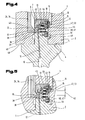
- FIG. 4 and FIG. 5 show in sectional view a further embodiment of a bending tool 1 according to the invention, used in a tool holder 2 of a press beam 3 of a bending machine, not shown, in particular press brake.
- the contact element 13, which is connected via a dash-dotted connection line 12 to a functional element 10 in the bending tool 1, is located in FIG Fig. 4 at rest 21 and thereby has a distance 27 (see Fig. 3 ) to the contact surface 14, whereby the connection between the functional element 10 and a power source or control device is interrupted on the bending machine.
- Such clamping elements 34 are part of the tool clamping for upper tools or lower tools on bending machines, especially press brakes and can be simultaneously used in a bending tool 1 according to the invention to move the contact element 13 from the rest position 21 in the contact position 23.
- the clamping element 34 in this case has a wedge element 35, which is oriented approximately to the right in the illustrated embodiment and can cooperate with a keyway 36 on the attachment extension 7 of the attachment portion 5 and thereby causes the clamping of the bending tool 1 in the tool holder 2.
- the actuating member 24 in the form of the clamping member 34 does not act directly on the contact element 13, but is on activation of the clamping member 34, so in a movement to the right, in the attachment extension 7 of the mounting portion 5 approximately horizontally adjustable mounted transmission element 37 here in the form a pressure bolt 38 is displaced together with a guide plate 39 to the right, whereby the contact element 13 connected to the guide plate 39 is also displaced to the right in the contact position 23 (see Fig. 5 ).
- the rest position of the contact element 13 with not activated clamping element 34 is effected in this embodiment by acting on the transmission element 37 to the left in the direction of the rest position 21 spring element 40 here in the form of a compression spring 41.
- the spring element 40 from 4 and FIG. 5 thus corresponds to the effect of the spring element 29 according to the Fig. 1 to 3 ,
- the pressure pin 38 and the contact element 13 to each other have a center distance 42, which even with small dimensions of the attachment extension 7 of the pressure pin 38 and the contact element 13 must not have extremely small dimensions and still have reasonably manageable dimensions.
- the guide plate 39 is oriented approximately at right angles to the mutually parallel adjustment of pressure pin 38 and contact element 13.
- the pressure pin 38 is cylindrical and guided approximately horizontally in a bore 43 in the attachment extension 7.
- the contact pin 38 is guided at its right, tapered end in a cover member 44 which closes the required for the pressure pin 38, the guide plate 39 and the contact element 13 movement spaces in the inner attachment extension 7 after assembly and further with an inserted in the cover member 44 electrically insulating guide sleeve 18, the contact element 13 additionally leads.
- the contact element 13 is divided into a firmly connected to the guide plate 39 sleeve member 45 and a coaxially guided therein pin member 46, wherein the axial force between the sleeve member 45 and pin member 46 by a in the sleeve part 45 arranged compression spring 47 is transmitted.
- the method for contacting the contact element 13 with the contact surface 14 thus proceeds in the following steps:
- the bending tool 1 is brought with the contact element 13 in the rest position to its intended position on the tool holder 2, in this embodiment, the attachment extension 7 inserted into the horritnut 6 until laterally adjoining the attachment extension 7 shoulder surfaces 48 on the side of the tool holder groove 6 subsequent contact surfaces 49 completely or at least approximately.
- This position can be achieved by means of a latching element formed on the fastening extension 7 50, which engages in a latching recess 51 in the tool holder groove 6, are secured, whereby even with not yet activated clamping device falling out of the bending tool 1 from the tool holder 2 is prevented.
- the tool clamping can be activated, whereby the clamping element 34, which simultaneously forms the actuator 24, is displaced to the right by means of an adjusting drive, whereby the wedge member 35 on the clamping element 34 in the keyway 36 on the attachment extension. 7 engages and thereby the bending tool 1 is pressed against the contact surfaces 49 of the tool holder 3.
- the pressure pin 38 positioned in the keyway 36 is shifted to the right, whereby the guide plate 39 connected thereto and the sleeve part 45 of the contact element 13 attached thereto are also displaced to the right.
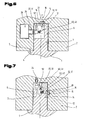
- Fig. 6 shows a further embodiment of a bending tool 1 according to the invention with the contact element 13 in rest position 21 in the intended position in the tool holder 2 used, but without activation of the contact by the actuator 24.
- the actuator 24 and contact element 13 arranged between transmission element 37 is in this embodiment by a Swivel lever 51 is formed, which is adjustably mounted by means of a pivot bearing 52 on the attachment portion 5, here the attachment extension 7 and the adjustment of the actuator 24 transmits to the contact element 13, whereby this starting from the illustrated rest position 21 in a contact surface 14 contacting, not shown here Contact position is spent and thereby again an electrical connection between the leading to the functional element 10 connecting line 12 and the power supply source or control device leading connection line 16 is produced.
- the approximately horizontal adjusting movement of the actuating member 24 is converted by means of the pivot lever 51 in an approximately vertical adjustment movement of the contact element 13, which is why This embodiment is particularly suitable when the actuator 24 and the contact surface 14 are not diametrically opposed to the receiving portion 4 of the tool holder 2.
- the rest position 21 of the contact element 13 with not activated actuator 24 is effected in this embodiment by acting on the transmission element 37 spring element 40, here in the form of a compression spring 41.
- Fig. 7 shows a further embodiment of a bending tool according to the invention 1 used in a tool holder 2 according to the invention, in which the actuator 24 in the Malawinut 6 is approximately vertically downwards and transmit its movement by means of a pivot lever 51 on the approximately horizontal in the attachment extension 7 adjustably mounted contact element 13 becomes.
- an elastic connecting element 53 is arranged between the transmission element 37 in the form of the pivot lever 51 and the contact element 13, whereby again the contact forces occurring between the contact portion 20 of the contact element 13 and the contact surface 14 can be limited.
- the rest position 21 of the contact element with not activated actuator 24 is characterized by a in Fig. 7 shown in dashed lines, acting on the transmission element 37 spring element 40, here in the form of a compression spring 41, causes.
- the adjusting drive 26 can be formed in this and in the other embodiments by, in particular by an electrically or fluidly driven actuator.
Abstract
Description
Die Erfindung betrifft ein Biegewerkzeug gemäß Oberbegriff des Patentanspruchs 1 sowie eine Werkzeugaufnahme gemäß Oberbegriff des Patentanspruchs 15, weiters eine Biegemaschine gemäß Oberbegriff des Patentanspruchs 19 und ein Verfahren zur elektrischen Koppelung eines Biegewerkzeuges mit einer Werkzeugaufnahme gemäß Oberbegriff des Patentanspruchs 20.The invention relates to a bending tool according to the preamble of
Bei Biegemaschinen, insbesondere Abkantpressen können in den Werkzeugaufnahmen für Oberwerkzeug oder Unterwerkzeug abhängig von den zu biegenden Werkstücken unterschiedlichste Werkzeuge eingesetzt werden. Für die voll- oder teilautomatisierte Herstellung von Biegeteilen sind die Biegemaschinen mit speicherprogrammierbaren elektronischen Steuervorrichtungen ausgestattet, die aufgrund von Informationen über das zu biegende Werkstück und Informationen über die jeweils verwendeten Biegewerkzeuge die Durchführung von exakten und optimierten Biegevorgängen ermöglichen.In bending machines, especially press brakes can be used in the tool holders for upper tool or lower tool depending on the workpieces to be bent a variety of tools. For the fully or partially automated production of bent parts, the bending machines are equipped with programmable electronic control devices, which allow the execution of exact and optimized bending operations based on information about the workpiece to be bent and information about the respective bending tools used.
Für diesen Zweck sind bereits Biegewerkzeuge bekannt, die von der Steuervorrichtung anhand von Informationen, die vom Biegewerkzeug an die Steuervorrichtung übertragen werden, identifiziert werden können, oder an denen Messelemente, insbesondere elektrische Messgeber angeordnet oder integriert sind und dadurch während eines Biegevorgangs Messwerte, insbesondere Informationen über den Biegevorgang oder das zu biegende Werkstück an die Steuervorrichtung übertragen werden können. Diese Übertragung erfolgt in vielen Fällen über elektrische Kontakte, die zwischen Biegewerkzeug und Werkzeugaufnahme zusammen eine elektrische Schnittstelle bilden, wobei im eingesetzten Zustand der Biegewerkzeuge Kontakte an einem Befestigungsabschnitt eines Biegewerkzeugs mit Kontakten an einem Aufnahmeabschnitt der Werkzeugaufnahme in berührende elektrische Verbindung gebracht werden, wodurch ein Funktionselement des Biegewerkzeugs, bspw. ein Informationsträger oder ein Messelement mit einer Steuervorrichtung der Biegemaschine in Verbindung gebracht werden kann. Über eine derartige elektrische Schnittstelle zwischen Biegewerkzeug und Werkzeugaufnahme fließende Ströme können dabei sowohl der Energieversorgung eines Funktionselements im Biegewerkzeug als auch der Datenübertragung zwischen dem Funktionselement und der Steuervorrichtung dienen.Bending tools are already known for this purpose, which can be identified by the control device on the basis of information transmitted by the bending tool to the control device, or on which measuring elements, in particular electrical measuring sensors are arranged or integrated and thereby measured values, in particular information, during a bending operation can be transmitted to the control device via the bending process or the workpiece to be bent. This transfer takes place in many cases via electrical contacts which form an electrical interface between the bending tool and tool holder, wherein in the inserted state of the bending tools contacts are brought to a mounting portion of a bending tool with contacts on a receiving portion of the tool holder in touching electrical connection, whereby a functional element the bending tool, for example, an information carrier or a measuring element with a control device of the bending machine can be brought into connection. Currents flowing through such an electrical interface between the bending tool and the tool holder can serve both to supply energy to a functional element in the bending tool and to transfer data between the functional element and the control device.
Aus dem Stand der Technik ist es bekannt, am Biegewerkzeug federnd gelagerte Kontaktstifte vorzusehen, die beim Einsetzen des Biegewerkzeugs in die Werkzeugaufnahme von den Kontaktflächen der Werkzeugaufnahme entgegen einer Federkraft geringfügig eingedrückt werden und dadurch mit Vorspannung gegen die Kontaktflächen gedrückt werden, wodurch die elektrische Verbindung zwischen dem Funktionselement im Biegewerkzeug und einer Stromversorgung oder einer Steuervorrichtung der Biegemaschine hergestellt werden kann.From the prior art it is known to provide the bending tool spring-mounted contact pins which are slightly depressed against the insertion of the bending tool into the tool holder of the contact surfaces of the tool holder against a spring force and are thereby pressed with bias against the contact surfaces, whereby the electrical connection between the functional element in the bending tool and a power supply or a control device of the bending machine can be produced.
Nachteilig bei dieser Art der Kontaktierung ist es, dass die Kontaktstifte gegenüber dem nicht in die Werkzeugaufnahme eingesetzten Biegewerkzeug vorragen und daher häufig mechanischen Belastungen ausgesetzt werden können, die Beschädigungen der Kontaktstifte bzw. der Kontaktstiftführungen und der federnden Lagerung verursachen können. Weiters finden wenn das Biegewerkzeug nicht in Richtung der Kontaktstifte an die Werkzeugaufnahme angenähert wird, Schleifvorgänge zwischen den Kontaktstiften und der Werkzeugaufnahme statt, die einen Verschleiß der kontaktierenden Oberflächen bewirken und deshalb die elektrische Verbindung zwischen Biegewerkzeug und Werkzeugaufnahme auf Dauer nicht sicher gestellt ist.A disadvantage of this type of contact is that the contact pins protrude from the bending tool not used in the tool holder and therefore often mechanical stresses can be exposed, which can cause damage to the pins or the contact pin guides and the resilient mounting. Furthermore, when the bending tool is not approached in the direction of the contact pins on the tool holder, grinding operations between the contact pins and the tool holder take place, which cause wear of the contacting surfaces and therefore the electrical connection between the bending tool and tool holder is not ensured in the long run.
Die Aufgabe der Erfindung besteht darin, eine Schnittstelle zur elektrischen Verbindung eines . Funktionselements an einem Biegewerkzeug mit einer Kontaktfläche an einer Werkzeugaufnahme einer Biegemaschine bereit zu stellen, die dauerhaft eine hohe Zuverlässigkeit aufweist.The object of the invention is an interface for the electrical connection of a. Functional element to provide a bending tool with a contact surface on a tool holder of a bending machine, which permanently has a high reliability.
Die Aufgabe der Erfindung wird durch ein Biegewerkzeug mit den Merkmalen des Anspruchs 1 gelöst, wonach das Biegewerkzeug einen mit einem Aufnahmeabschnitt der Werkzeugaufnahme koppelbaren Befestigungsabschnitt und ein verstellbar gelagertes Kontaktelement zur elektrischen Verbindung eines am Biegewerkzeug ausgebildeten Funktionselement mit einer Kontaktfläche am Aufnahmeabschnitt der Werkzeugaufnahme umfasst, und dabei das Kontaktelement durch ein am Aufnahmeabschnitt der Werkzeugaufnahme angeordnetes Betätigungsorgan aus einer zur Kontaktfläche beabstandeten Ruhestellung bezogen auf eine Außenfläche des Befestigungsabschnitts nach außen in eine die Kontaktfläche berührende Kontaktstellung bringbar ist.The object of the invention is achieved by a bending tool with the features of
Das Kontaktelement, bspw. in Form eines Kontaktstiftes, wird also nicht wie im Stand der Technik durch eine Kontaktfläche an der Werkzeugaufnahme aus einer Ruhestellung nach innen in die Kontaktstellung gedrückt, sondern durch ein eigenes Betätigungsorgan an der Werkzeugaufnahme aktiv aus einer Ruhestellung nach außen in eine die Kontaktfläche berührende Kontaktstellung verbracht.The contact element, for example, in the form of a contact pin, is therefore not as in the prior art by a contact surface on the tool holder from a rest position to pressed inside the contact position, but actively spent by a separate actuator on the tool holder from a rest position to the outside in a contact surface contacting contact position.
Eine mit dem erfindungsgemäßen Biegewerkzeug zusammenwirkende erfindungsgemäße Werkzeugaufnahme an einer Biegemaschine weist gemäß Anspruch 15 einen Aufnahmeabschnitt zum Ankoppeln eines Befestigungsabschnitts eines Biegewerkzeugs sowie eine elektrisch leitfähige, mit einer Stromversorgungseinrichtung oder einer Steuervorrichtung verbundene Kontaktfläche am Aufnahmeabschnitt auf, wobei zur bedarfsweisen Verstellung eines am Befestigungsabschnitt des Biegewerkzeugs zwischen einer Ruhestellung und einer Kontaktstellung verstellbar gelagerten Kontaktlements am Aufnahmeabschnitt der Werkzeugaufnahme ein verstellbar gelagertes, mit einem Verstellantrieb verbundenes und das Kontaktelement in die Kontaktstellung bringendes Betätigungsorgan angeordnet ist.A cooperating with the bending tool according to the invention inventive tool holder on a bending machine has according to claim 15 a receiving portion for coupling a mounting portion of a bending tool and an electrically conductive, connected to a power supply device or a control device contact surface on the receiving portion, wherein for an adjustment on the attachment portion of the bending tool between a rest position and a contact position adjustably mounted Kontaktlements on the receiving portion of the tool holder is an adjustably mounted, connected to an adjustment and the contact element in the contact position-bringing actuator is arranged.
Die Betätigung des Kontaktelements, also das Verstellen des Kontaktelements aus der Ruhestellung in die Kontaktstellung erfolgt dabei nicht wie im Stand der Technik mittels der Innenkontur des Aufnahmeabschnitts, insbesondere mittels der Kontaktfläche, sondern durch ein eigenes aktiv antreibbares Betätigungsorgan im Aufnahmeabschnitt der Werkzeugaufnahme.The actuation of the contact element, so the adjustment of the contact element from the rest position to the contact position is not carried out as in the prior art by means of the inner contour of the receiving portion, in particular by means of the contact surface, but by a separate active drivable actuator in the receiving portion of the tool holder.
Eine erfindungsgemäße Biegemaschine gemäß Anspruch 19, insbesondere eine Abkantpresse mit einer Werkzeugaufnahme und einem mit dieser koppelbaren Biegewerkzeug weist eine erfindungsgemäße Werkzeugaufnahme sowie ein damit zusammenwirkendes erfindungsgemäßes Biegewerkzeug auf.A bending machine according to the invention according to
Die Aufgabe der Erfindung wird weiters gelöst durch ein Verfahren zur elektrischen Kopplung eines Funktionselements an einem Biegewerkzeug mit einer Kontaktfläche an einer Werkzeugaufnahme mittels eines am Biegewerkzeug verstellbar gelagerten Kontaktelements, wobei erfindungsgemäß in einem ersten Schritt das Biegewerkzeug in seine bestimmungsgemäße Position an der Werkzeugaufnahme verbracht wird und in einem darauf folgenden zweiten Schritt das Kontaktelement mittels eines an der Werkzeugaufnahme ausgebildeten Betätigungsorgans aus einer zur Kontaktfläche beabstandeten Ruhestellung in eine die Kontaktfläche berührende Kontaktstellung verstellt wird. Das zumindest eine Kontaktelement ist dadurch beim Einsetzen des Biegewerkzeugs in die Werkzeugaufnahme nicht, wie im Stand der Technik, mechanischen Belastungen ausgesetzt, sondern wird erst nach Erreichen der bestimmungsgemäßen Position aktiviert, wodurch das Einsetzen bzw. Entfernen des Biegewerkzeugs an der Werkzeugaufnahme keinen Verschleiß am Kontaktelement oder an der Kontaktfläche verursacht.The object of the invention is further achieved by a method for electrically coupling a functional element on a bending tool with a contact surface on a tool holder by means of a bending tool adjustably mounted contact element, according to the invention in a first step, the bending tool is moved to its intended position on the tool holder and In a subsequent second step, the contact element is adjusted by means of an actuator formed on the tool holder from a distance to the contact surface rest position in a contact surface contacting the contact position. That is at least one contact element as a result, when the bending tool is inserted into the tool holder, it is not subjected to mechanical stresses as in the prior art, but is activated only after reaching the intended position, whereby the insertion or removal of the bending tool on the tool holder does not cause wear on the contact element or on the contact surface ,
Ein Verschleiß an den Kontaktelementen während des Einsetzens bzw. während des Entfernens des Biegewerkzeugs wird insbesondere vermieden, wenn das Kontaktelement in der Ruhestellung mit der Außenfläche des Befestigungsabschnitts bündig oder gegen diese zurückversetzt ist. Dadurch ist auch eine mechanische Beschädigung des Kontaktelements bei der Handhabung des Biegewerkzeugs weitgehend ausgeschlossen, da das Kontaktelement nicht gegenüber die Außenoberfläche des Biegewerkzeugs vorragt.Wear on the contact elements during insertion or during removal of the bending tool is particularly avoided when the contact element is flush in the rest position with the outer surface of the mounting portion or set back against this. As a result, mechanical damage to the contact element during handling of the bending tool is largely excluded, since the contact element does not protrude with respect to the outer surface of the bending tool.
Das Betätigungsorgan an der Werkzeugaufnahme kann direkt auf das Kontaktelement mechanisch einwirken, es ist jedoch auch möglich, dass eine Bewegung des Betätigungsorgans mittels eines am Befestigungsabschnitts verstellbar gelagerten Übertragungselement auf das Kontaktelement übertragen wird, bspw. ein Druckstück oder einen Schwenkhebel oder ähnliches.The actuator on the tool holder can act directly on the contact element mechanically, but it is also possible that a movement of the actuator is transmitted by means of an adjustable mounting portion on the transfer element mounted on the contact element, for example. A pressure piece or a pivot lever or the like.
Damit das zumindest eine Kontaktelement, wenn es nicht aktiv durch das Betätigungsorgan in die Kontaktstellung verbracht ist, selbstständig die Ruhestellung einnimmt, in der es einen Abstand zur Kontaktfläche der Werkzeugaufnahme aufweist oder gegenüber der Außenfläche des Befestigungsabschnitts zurückversetzt ist, ist es von Vorteil, wenn im Befestigungsabschnitt ein auf das Kontaktelement oder das Übertragungselement in Richtung der Ruhestellung einwirkendes Federelement angeordnet ist. Dadurch wird das Kontaktelement nach Deaktivierung des Betätigungsorgans der Werkzeugaufnahme selbsttätig durch das Federelement in die geschützte Ruhestellung verbracht.Thus, the at least one contact element, if it is not actively spent by the actuator in the contact position, automatically assumes the rest position in which it has a distance to the contact surface of the tool holder or set back relative to the outer surface of the mounting portion, it is advantageous if in Attachment section is arranged on the contact element or the transmission element in the direction of the rest position acting spring element. Characterized the contact element is automatically spent after deactivation of the actuator of the tool holder by the spring element in the protected rest position.
Das Kontaktelement kann dabei etwa geradlinig im Befestigungsabschnitt geführt sein, wodurch ein schonendes Antasten der Kontaktfläche sicher gestellt ist, insbesondere wenn die Führungsrichtung rechtwinkelig auf die Kontaktfläche orientiert ist. Weiters kann eine geradlinige Führung des Kontaktelements von Vorteil sein, wenn an der Werkzeugaufnahme das Betätigungsorgan und die Kontaktfläche etwa diametral bzgl. des dazwischen befindlichen Befestigungsabschnitts angeordnet sind.The contact element can thereby be guided approximately rectilinearly in the attachment section, whereby a gentle touching of the contact surface is ensured, in particular if the guide direction is oriented at right angles to the contact surface. Furthermore, a straight-line guide of the contact element may be advantageous if the actuating member and the contact surface are arranged approximately diametrically with respect to the fastening portion located therebetween on the tool holder.
Alternativ dazu kann das Kontaktelement mittels eines Schwenklagers im Befestigungsabschnitt geführt sein, etwa wenn das Betätigungsorgan und die Kontaktfläche an der Werkzeugaufnahme nicht diametral einander gegenüberliegen und die Verstellrichtung des Betätigungsorgans zur Verstellrichtung des Kontaktelements einen Winkel einschließt.Alternatively, the contact element may be guided by means of a pivot bearing in the attachment portion, such as when the actuator and the contact surface on the tool holder are not diametrically opposed to each other and the adjustment of the actuator to the adjustment of the contact element forms an angle.
Sinngemäß kann im Fall eines zwischen dem Betätigungsorgan und dem Kontaktelement vorgesehenen Übertragungselements dieses ebenfalls geradlinig oder mittels eines Schwenklagers im Befestigungsabschnitt gerührt sein.Analogously, in the case of a provided between the actuator and the contact element transmission element this also be stirred in a straight line or by means of a pivot bearing in the attachment portion.
Das Kontaktelement kann aus Gründen einer einfachen Fertigung als zylindrischer Kontaktbolzen oder Kontaktstift ausgeführt sein.The contact element may be designed for reasons of ease of manufacture as a cylindrical contact pin or pin.
Ebenfalls aus Gründen einer einfachen Fertigung kann das Federelement als eine auf das Kontaktelement oder das Übertragungselement wirkende, insbesondere bereits in der Ruhestellung vorgespannte Druckfeder ausgebildet sein. Diese Ausführung bietet sich an, wenn das Kontaktelement als geradlinig geführter, zylindrischer Kontaktbolzen ausgeführt ist, wobei die Druckfeder den Kontaktbolzen konzentrisch umfassen kann und sich an einer Lochblende, die an der Außenfläche des Befestigungsabschnitts montiert ist, abstützt.Also for reasons of ease of manufacture, the spring element can be designed as a force acting on the contact element or the transmission element, in particular already biased in the rest position compression spring. This embodiment is useful when the contact element is designed as a rectilinear guided, cylindrical contact pin, wherein the compression spring can comprise the contact pin concentrically and is supported on a pinhole, which is mounted on the outer surface of the mounting portion.
Der Stromfluss zum bzw. vom Funktionselement erfolgt im einfachsten Fall einerseits über das im Allgemeinen metallische Biegewerkzeug, das die metallische Werkzeugaufnahme berührt und anderseits über das gegenüber dem restlichen Biegewerkzeug galvanisch getrennte Kontaktelement, es kann jedoch auch vorgesehen sein, für das Funktionselement zwei eigene, zueinander und zum Biegewerkzeug galvanisch getrennte Kontaktelemente vorzusehen. Weiters ist es möglich, dass in einem Biegewerkzeug mehrere Funktionselemente angeordnet sind, weshalb es vorteilhaft sein kann, wenn das Betätigungsorgan auf zumindest zwei Kontaktelemente oder zwei Übertragungselemente einwirkt.The flow of current to or from the functional element takes place in the simplest case on the one hand via the generally metallic bending tool that touches the metallic tool holder and on the other hand via the opposite electrically conductive contact element to the rest of the bending tool, but it can also be provided for the functional element two own, to each other and to provide the bending tool galvanically isolated contact elements. Furthermore, it is possible that a plurality of functional elements are arranged in a bending tool, which is why it may be advantageous if the actuating member acts on at least two contact elements or two transmission elements.
Ebenso kann das Biegewerkzeug auch ein Übertragungselement aufweisen, das auf zumindest zwei Kontaktelemente einwirkt. Durch diese beiden Ausrührungsmöglichkeiten kann trotz mehrerer Kontaktelemente auf den Einsatz mehrerer Betätigungsorgane oder mehrer Übertragungselemente verzichtet werden, wodurch sich baulich einfache Lösungen ergeben.Likewise, the bending tool may also have a transmission element which acts on at least two contact elements. Due to these two Ausrührungsmöglichkeiten despite multiple contact elements can be dispensed with the use of multiple actuators or several transmission elements, resulting in structurally simple solutions.
Da das Kontaktelement vom restlichen Biegewerkzeug oder von weiteren Kontaktelementen galvanisch getrennt sein muss, kann dieses in einer elektrisch isolierenden Führungshülse gerührt sein oder das Kontaktelement an seinen mit der Führungshülse in Kontakt tretenden Oberflächenabschnitten ein elektrisch isolierendes Material aufweisen während die elektrisch leitende Kontaktfläche des Kontaktelements mit dem Biegewerkzeug bzw. der Führungshülse nicht in Kontakt tritt, wodurch sowohl die Funktion der galvanischen Trennung des Kontaktelements bzw. der an diesem angeordneten elektrisch leitenden Kontaktfläche vom Biegewerkzeug als auch die mechanische Führung des Kontaktelements bewerkstelligt wird.Since the contact element from the rest of the bending tool or other contact elements must be electrically isolated, this can be stirred in an electrically insulating guide sleeve or the contact element at its passing with the guide sleeve surface portions have an electrically insulating material while the electrically conductive contact surface of the contact element with the Bending tool or the guide sleeve does not come into contact, whereby both the function of the galvanic separation of the contact element or arranged on this electrically conductive contact surface of the bending tool and the mechanical guidance of the contact element is accomplished.
Ein zusätzlicher Schutz des Elements während der Handhabung außerhalb der Werkzeugaufnahme wird erzielt, wenn ein ggf. die Kontaktfläche berührender Kontaktabschnitt des Kontaktelements in der Ruhestellung vollständig in der Führungshülse eingezogen ist. Der den Stromübergang zur Kontaktfläche bewirkende Kontaktabschnitt des Kontaktelements ist dadurch auch weitgehend vor Verschmutzung geschützt, wodurch ein geringer Übergangswiderstand an deren Berührstellen zwischen Kontaktelement und Kontaktfläche gegeben ist.An additional protection of the element during handling outside of the tool holder is achieved when a possibly contacting the contact surface contact portion of the contact element is completely retracted in the rest position in the guide sleeve. The contact section of the contact element which brings about the current transition to the contact surface is thus also largely protected against contamination, as a result of which a low contact resistance at its points of contact between contact element and contact surface is ensured.
Die Führungshülse kann dabei insbesondere aus einem Material ausgewählt aus einer Gruppe umfassend Metalle und Kunststoffe mit niedrigem Gleitreibungskoeffiezient gebildet sein.The guide sleeve can be formed in particular from a material selected from a group comprising metals and plastics with a low coefficient of sliding friction.
Um unnötig hohe Kontaktkräfte zwischen Kontaktelement und Kontaktfläche bzw. Kontaktelement und Übertragungselement zu vermeiden, ist es möglich, dass zwischen Kontaktelement und Übertragungselement ein elastisches Verbindungselement angeordnet ist. Das elastische Verbindungselement kann dabei wiederum als Federelement bspw. als Druckfeder oder Zugfeder aus einem Metall ausgebildet sein oder aber auch durch ein Verbindungselement aus Elastomermaterial gebildet sein.In order to avoid unnecessarily high contact forces between the contact element and contact surface or contact element and transmission element, it is possible that an elastic connecting element is arranged between the contact element and the transmission element. The elastic connecting element can in turn be designed as a spring element, for example, as a compression spring or tension spring made of a metal or else be formed by a connecting element made of elastomeric material.
Alternativ dazu kann am Kontaktelement selbst oder am Übertragungselement selbst ein elastisch verformbarer Teilabschnitt ausgebildet sein, der ein eigenes zusätzliches Verbindungselement entbehrlich macht, indem sich zumindest einer der beiden Teile soweit verformen kann, dass extreme Kontaktkräfte vermieden werden, wenn der Verstellweg des Betätigungsorgans durch ein feststehendes Anschlagelement begrenzt wird.Alternatively, it can be formed on the contact element itself or on the transmission element itself an elastically deformable portion that makes its own additional connection element dispensable by at least one of the two parts can deform so far that extreme contact forces are avoided when the adjustment of the actuator by a fixed Stop element is limited.
Zur Verringerung des Kontaktwiderstandes ist es von Vorteil, wenn das Kontaktelement zumindest in einem ggf. die Kontaktfläche kontaktierenden Kontaktabschnitt eine hartvergoldete Oberfläche aufweist, die zusätzlich auch verschleißfest ist.In order to reduce the contact resistance, it is advantageous if the contact element has a hard-gold-plated surface at least in a contact section which possibly makes contact with the contact surface and which is additionally wear-resistant.
Wie bereits zuvor erwähnt, kann das Funktionselement am Biegewerkzeug durch ein Messelement, insbesondere einen elektrischen Messgeber gebildet sein, wodurch, vor, während oder nach der Bearbeitung und/oder Umformung vorhandene Eigenschaften des Werkstücks, beispielsweise mechanische Größen, erfasst und der Steuervorrichtung der Biegemaschine zugeführt werden können.As already mentioned above, the functional element can be formed on the bending tool by a measuring element, in particular an electrical measuring transducer, whereby, before, during or after machining and / or reshaping existing properties of the workpiece, such as mechanical variables detected and supplied to the control device of the bending machine can be.
Das Messelement kann insbesondere zur Erfassung einer geometrischen Größe eines mit dem Biegewerkzeug zu bearbeitenden Werkstücks ausgebildet sein, bspw. eines Biegewinkels am Werkstück im belasteten und/oder unbelasteten Zustand oder bspw. die Dicke des Werkstücks vor der Biegeverformung.The measuring element can be designed in particular for detecting a geometric size of a workpiece to be machined with the bending tool, for example a bending angle on the workpiece in the loaded and / or unloaded state or, for example, the thickness of the workpiece before the bending deformation.
Weiters kann das Funktionselement ein Speicherelement, insbesondere zur Speicherung von Werkzeugdaten umfassen, wodurch der Steuervorrichtung entweder direkt aus dem Speicherelement Parameter des Biegewerkzeugs übergeben werden oder nach einer Identifikation des eingesetzten Biegewerkzeugs in einem Speicher außerhalb des Biegewerkzeugs hinterlegte Werkzeugparameter eingelesen werden können.Furthermore, the functional element can comprise a memory element, in particular for storing tool data, whereby the control device can be transferred either directly from the memory element parameters of the bending tool or after an identification of the bending tool used can be read in a memory stored outside the bending tool tool parameters.
Einen einfachen Aufbau der Werkzeugaufnahme kann man dadurch erzielen, wenn das Betätigungsorgan durch ein den Befestigungsabschnitt am Aufnahmeabschnitt fixierendes Klemmelement gebildet wird. Derartige Klemmelemente sind insbesondere zur Fixierung von Oberwerkzeugen an der Werkzeugaufnahme eines oberen Pressbalkens ohnehin vorhanden und können dadurch gleichzeitig als Betätigungsorgan für das Kontaktelement eingesetzt werden.A simple construction of the tool holder can be achieved if the actuating member is formed by a fastening element fixing the fixing portion on the receiving portion. Such clamping elements are available in any case for the fixation of upper tools on the tool holder of an upper press beam anyway and can thereby be used simultaneously as an actuator for the contact element.
Das Klemmelement kann dabei insbesondere als Keilelement ausgebildet sein, das mit einer Keilnut am Befestigungsabschnitt des Biegewerkzeugs zusammenwirkt. Durch die zwischen Keilelement und Keilnut wirkenden Klemmkräfte kann eine sehr stabile und präzise Fixierung des Biegewerkzeugs an der Werkzeugaufnahme erfolgen und gleichzeitig ist ein in der Keilnut am Befestigungsabschnitt angeordnetes Betätigungsorgan während der Handhabung außerhalb der Werkzeugaufnahme vor Beschädigungen gut geschützt.The clamping element can be designed in particular as a wedge element, which cooperates with a keyway on the attachment portion of the bending tool. By acting between wedge element and keyway clamping forces can be a very stable and precise fixation of the bending tool on the tool holder and at the same time is one in the keyway arranged on the attachment portion actuator during handling outside the tool holder from damage well protected.
Der Aufnahmeabschnitt der Werkzeugaufnahme umfasst in einer vorteilhaften Weiterbildung der Erfindung eine Werkzeugaufnahmenut, in der das Betätigungsorgan sowie die Kontaktfläche angeordnet sein können und dadurch gut vor Beschädigungen geschützt sind. Die Werkzeugaufnahmenut erstreckt sich dabei insbesondere in Längsrichtung eines Pressbalkens oder eines Presstisches, wodurch die Position des Biegewerkzeugs entlang des Pressbalkens bzw. des Presstisches frei gewählt werden kann.The receiving portion of the tool holder comprises in an advantageous development of the invention, a tool holder groove in which the actuator and the contact surface can be arranged and are thus well protected from damage. The tool receiving groove extends in particular in the longitudinal direction of a press beam or a press table, whereby the position of the bending tool along the press beam or the press table can be chosen freely.
Um wiederum den Kontaktwiderstand an den Berührstellen zwischen Kontaktelement und Kontaktfläche gering zu halten, weist die Kontaktfläche zumindest abschnittsweise eine hartvergoldete Oberfläche auf.In order in turn to keep the contact resistance at the contact points between the contact element and the contact surface small, the contact surface has, at least in sections, a hard-gold plated surface.
Um ein erfindungsgemäßes Biegewerkzeug an verschiedenen Positionen an der Werkzeugaufnahme positionieren zu können, ist es von Vorteil, wenn die Kontaktfläche an einer sich in einer Längsrichtung des Aufnahmeabschnitts erstreckenden, insbesondere in einer Werkzeugaufnahmenut angeordneten Kontaktschiene ausgebildet ist. Für die Kontaktierung mit unterschiedlichen Kontaktelementen an einem oder mehreren Biegewerkzeugen können insbesondere mehrere parallel zueinander verlaufende Kontaktschienen ausgebildet sein.In order to be able to position a bending tool according to the invention at different positions on the tool holder, it is advantageous if the contact surface is formed on a contact rail extending in a longitudinal direction of the receiving portion and arranged in particular in a tool receiving groove. For contacting with different contact elements on one or more bending tools, in particular a plurality of mutually parallel contact rails may be formed.
Um eine galvanische Trennung zwischen der Kontaktfläche und der restlichen Werkzeugaufnahme zu erzielen, kann die Kontakttläche durch zumindest eine auf einem elektrisch isolierenden Trägerelement angebrachte Leiterbahn gebildet sein.In order to achieve a galvanic separation between the contact surface and the rest of the tool holder, the contact surface may be formed by at least one conductor track mounted on an electrically insulating carrier element.
Der Verstellantrieb für die Verstellung des Betätigungsorgans an der Werkzeugaufnahme kann durch einen fluidisch oder elektrisch betriebenen Aktor gebildet sein.The adjusting drive for the adjustment of the actuating member on the tool holder can be formed by a fluidically or electrically operated actuator.
Die Erfindung wird im nachfolgenden anhand der in den Zeichnungen dargestellten Ausfiihrungsbeispiele näher erläutert.The invention will be explained in more detail below with reference to the exemplary embodiments illustrated in the drawings.
Es zeigen jeweils in vereinfachter schematischer Darstellung:
- Fig. 1
- einen Schnitt durch eine erfindungsgemäße Werkzeugaufnahme mit einem darin nicht vollständig eingesetzten, erfindungsgemäßen Biegewerkzeug mit einem Kontaktelement in Ruhestellung;
- Fig. 2
- einen Ausschnitt durch die Werkzeugaufnahme gemäß
Fig. 1 mit dem vollständig eingesetzten Biegewerkzeug und dem Kontaktelement des Biegewerkzeugs in Kontaktstellung; - Fig. 3
- einen Detailausschnitt des Biegewerkzeugs und der Werkzeugaufnahme in der Kontaktstellung des Kontaktelements gemäß
Fig. 2 ; - Fig. 4
- eine weitere Ausführungsform einer erfindungsgemäßen Werkzeugaufnahme mit einem darin eingesetzten, jedoch noch nicht fixiertem erfindungsgemäßem Biegewerkzeug mit dem Kontaktelement in Ruhestellung;
- Fig. 5
- die Werkzeugaufnahme gemäß
Fig. 4 mit dem darin fixierten Biegewerkzeug mit dem Kontaktelement in Kontaktstellung; - Fig. 6
- eine weitere mögliche Ausführungsform eines erfindungsgemäßen Biegewerkzeugs mit einem schwenkgelagerten Kontaktelement;
- Fig. 7
- eine weitere Ausführungsform eines erfindungsgemäßen Biegewerkzeugs mit einem schwenkgelagerten Übertragungselement.
- Fig. 1
- a section through a tool holder according to the invention with a therein not completely used, bending tool according to the invention with a contact element in the rest position;
- Fig. 2
- a section through the tool holder according to
Fig. 1 with the fully inserted bending tool and the contact element of the bending tool in the contact position; - Fig. 3
- a detail of the bending tool and the tool holder in the contact position of the contact element according to
Fig. 2 ; - Fig. 4
- a further embodiment of a tool holder according to the invention with an inserted therein, but not yet fixed inventive bending tool with the contact element in the rest position;
- Fig. 5
- the tool holder according to
Fig. 4 with the bending tool fixed therein with the contact element in contact position; - Fig. 6
- another possible embodiment of a bending tool according to the invention with a pivotally mounted contact element;
- Fig. 7
- a further embodiment of a bending tool according to the invention with a pivotally mounted transmission element.
Einführend sei festgehalten, dass in den unterschiedlich beschriebenen Ausführungsformen gleiche Teile mit gleichen Bezugszeichen bzw. gleichen Bauteilbezeichnungen versehen werden, wobei die in der gesamten Beschreibung enthaltenen Offenbarungen sinngemäß auf gleiche Teile mit gleichen Bezugszeichen bzw. gleichen Bauteilbezeichnungen übertragen werden können. Auch sind die in der Beschreibung gewählten Lageangaben, wie z.B. oben, unten, seitlich usw. auf die unmittelbar beschriebene sowie dargestellte Figur bezogen und sind bei einer Lageänderung sinngemäß auf die neue Lage zu übertragen. Weiters können auch Einzelmerkmale oder Merkmalskombinationen aus den gezeigten und beschriebenen unterschiedlichen Ausführungsbeispielen für sich eigenständige, erfinderische oder erfindungsgemäße Lösungen darstellen.By way of introduction, it should be noted that in the differently described embodiments, the same parts are provided with the same reference numerals or the same component names, the disclosures contained in the entire description can be mutatis mutandis to the same parts with the same reference numerals or component names. Also, the position information selected in the description, such as top, bottom, side, etc. related to the immediately described and illustrated figure and are to be transferred to a new position analogous to the new situation. Furthermore, individual features or combinations of features from the shown and described different Represent examples of their own, inventive or inventive solutions.
Sämtliche Angaben zu Wertebereichen in gegenständlicher Beschreibung sind so zu verstehen, dass diese beliebige und alle Teilbereiche daraus mit umfassen, z.B. ist die Angabe 1 bis 10 so zu verstehen, dass sämtliche Teilbereiche, ausgehend von der unteren Grenze 1 und der oberen Grenze 10 mitumfasst sind, d.h. sämtliche Teilbereich beginnen mit einer unteren Grenze von 1 oder größer und enden bei einer oberen Grenze von 10 oder weniger, z.B. 1 bis 1,7, oder 3,2 bis 8,1 oder 5,5 bis 10.All statements on ranges of values in the description of the present invention should be understood to include any and all sub-ranges thereof, e.g. the
Am Biegwerkzeug 1, im dargestellten Ausführungsbeispiel in dessen Inneren ist ein Funktionselement 10, bspw. in Form eines elektrischen Messgebers 11 angeordnet, der zur Stromversorgung und/oder Übertragung von Messsignalen mit einer elektrisch leitfähigen, strichpunktiert dargestellten Verbindungsleitung 12 verbunden ist. Zur Herstellung einer elektrisch leitenden Verbindung zwischen dem Funktionselement 10 und einer nicht dargestellten Stromversorgungsquelle oder einer Steuervorrichtung der Biegemaschine führt die Verbindungsleitungsleitung 12 zu einem am Befestigungsabschnitt 5 angeordneten Kontaktelement 13, das mit einer Kontaktfläche 14 am Aufnahmeabschnitt 4 der Werkzeugaufnahme 2 in Kontakt gebracht werden kann. Von dieser Kontaktfläche 14, die bspw. an der Oberfläche einer Kontaktschiene 15, die sich in Längsrichtung der Werkzeugaufnahmenut 6 erstreckt angeordnet ist, führt eine weitere ebenfalls strichpunktiert dargestellte Verbindungsleitung 16 zur nicht dargestellten Stromversorgungsquelle oder Steuervorrichtung.On the
Das Kontaktelement 13 ist im dargestellten Ausführungsbeispiel als zylindrischer Kontaktstift 17 ausgebildet, dessen stromführende Teile gegenüber dem restlichen Biegewerkzeug 1 mittels einer elektrisch isolierenden Führungshülse 18 galvanisch getrennt sind. Das Kontaktelement 13 am Befestigungsabschnitt 5 und die Kontaktfläche 14 am Aufnahmeabschnitt 4 sind dabei jeweils so angeordnet, dass Kontaktelement 13 und Kontaktfläche 14 bei bestimmungsgemäßer Positionierung des Biegewerkzeugs 1 an der Werkzeugaufnahme 2 einander unmittelbar gegenüberliegen und in dieser Positionierung des Biegewerkzeugs 1 eine elektrische Verbindung zwischen den Funktionselement 10 und der Stromversorgungsquelle bzw. der Steuervorrichtung hergestellt werden kann. Im dargestellten Ausführungsbeispiel ist die Kontaktfläche 14 etwa bündig mit einer Seitenfläche der Werkzeugaufnahmenut 6 und das Kontaktelement 13 in Form des Kontaktstiftes 17 ist etwa rechtwinkelig bzgl. einer Mittelebene 19 der Werkzeugaufnahmenut 6 bzw. des Biegewerkzeugs 1 orientiert.The
Am in
Um eine Verbindung zwischen dem Funktionselement 10 und der Stromversorgungsquelle bzw. der Steuervorrichtung herzustellen, wird wie in
Ausgehend von dieser Stellung, bei der das Biegewerkzeug 1 sich bereits in seiner bestimmungsgemäßen Position an der Werkzeugaufnahme 2 befindet, jedoch das Kontaktelement 13 noch in Ruhestellung 21 ist, wird mittels des Betätigungsorgans 24 am Aufnahmeabschnitt 4 das Kontaktelement 13 in Verstellrichtung 28 nach rechts verschoben, wodurch der Kontaktabschnitt 20 die Kontaktfläche 14 berührt und der Stromkreis zwischen Funktionselement 10 und Stromversorgungsquelle bzw. Steuervorrichtung zumindest an der Schnittstelle zwischen Biegewerkzeug 1 und Werkzeugaufnahme 2 geschlossen ist. Während in den Figuren jeweils nur ein Kontaktelement 13 dargestellt ist, können selbstverständlich gleichzeitig auch mehrere Kontaktelemente 13, 13', ... mit einer oder mehreren Kontaktflächen 14, 14', ... in elektrische Verbindung gebracht werden.Starting from this position, in which the
Damit das Kontaktelement 13 die Ruhestellung 21 selbsttätig einnimmt, sobald die Betätigung durch das Betätigungsorgan 24 aufgehoben wird, ist ein auf das Kontaktelement 13 in Richtung der Ruhestellung 21 wirkendes Federelement 29 vorgesehen, dass zwischen dem verstellbaren Kontaktelement 13 und dem feststehenden Befestigungsabschnitt 5 wirksam ist. Wie in den
Wie
Die Ruhestellung des Kontaktelements 13 bei nicht aktiviertem Klemmelement 34 wird in diesem Ausführungsbeispiel durch ein auf das Übertragungselement 37 nach links in Richtung der Ruhestellung 21 wirkendes Federelement 40 hier in Form einer Druckfeder 41 bewirkt. Das Federelement 40 aus
Durch die Verwendung der Führungsplatte 39 können der Druckbolzen 38 und das Kontaktelement 13 zueinander einen Achsabstand 42 aufweisen, wodurch auch bei kleinen Abmessungen des Befestigungsfortsatzes 7 der Druckbolzen 38 und das Kontaktelement 13 keine extrem kleinen Abmessungen aufweisen müssen und noch einigermaßen handhabbare Dimensionen aufweisen. Die Führungsplatte 39 ist dazu etwa rechtwinkelig zu den zueinander parallelen Verstellrichtungen von Druckbolzen 38 und Kontaktelement 13 orientiert. Der Druckbolzen 38 ist zylindrisch ausgeführt und in einer Bohrung 43 im Befestigungsfortsatz 7 etwa horizontal geführt. Zusätzlich ist der Kontaktbolzen 38 an seinem rechten, verjüngtem Ende in einem Deckelelement 44 geführt, das die für den Druckbolzen 38, die Führungsplatte 39 sowie das Kontaktelement 13 erforderlichen Bewegungsräume im inneren Befestigungsfortsatzes 7 nach deren Montage verschließt und weiters mit einer im Deckelelement 44 eingesetzten elektrisch isolierenden Führungshülse 18 das Kontaktelement 13 zusätzlich führt. Zur Begrenzung der Kontaktkraft zwischen dem Kontaktabschnitt 20 des Kontaktelements 13 und der Kontaktfläche 14 ist das Kontaktelement 13 in einen mit der Führungsplatte 39 fest verbundenen Hülsenteil 45 und ein darin koaxial geführtes Stiftelement 46 unterteilt, wobei die axiale Kraft zwischen Hülsenteil 45 und Stiftelement 46 durch eine im Hülsenteil 45 angeordnete Druckfeder 47 übertragen wird.By using the
Das Verfahren zur Kontaktierung des Kontaktelements 13 mit der Kontaktfläche 14 läuft somit in folgenden Schritten ab:The method for contacting the
Zuerst wird das Biegewerkzeug 1 mit dem Kontaktelement 13 in Ruhestellung in seine bestimmungsgemäße Position an der Werkzeugaufnahme 2 gebracht, in diesem Ausführungsbeispiel also der Befestigungsfortsatz 7 in die Werkzeugaufnahmenut 6 eingeführt, bis seitlich an den Befestigungsfortsatz 7 anschließende Schulterflächen 48 an seitlich der Werkzeugaufnahmenut 6 anschließenden Anlageflächen 49 vollständig oder zumindest annähernd anliegen. Diese Position kann mittels eines am Befestigungsfortsatz 7 ausgebildeten Rastelements 50, das in eine Rastausnehmung 51 in der Werkzeugaufnahmenut 6 eingreift, gesichert werden, wodurch auch bei noch nicht aktivierter Klemmvorrichtung ein Herausfallen des Biegewerkzeugs 1 aus der Werkzeugaufnahme 2 verhindert ist.First, the
Wenn sich das Biegewerkzeug 1 in dieser Einsetzposition befindet, kann die Werkzeugklemmung aktiviert werden, wodurch das Klemmelement 34, das gleichzeitig das Betätigungsorgan 24 bildet, mittels eines Verstellantriebs nach rechts verschoben wird, wodurch das Keilelement 35 am Klemmelement 34 in die Keilnut 36 am Befestigungsfortsatz 7 eingreift und dadurch das Biegewerkzeug 1 gegen die Anlageflächen 49 der Werkzeugaufnahme 3 gepresst wird. Gleichzeitig wird der in der Keilnut 36 positionierte Druckbolzen 38 nach rechts verschoben, wodurch auch die mit diesem verbundene Führungsplatte 39 und der daran befestigte Hülsenteil 45 des Kontaktelements 13 nach rechts verschoben. Diese Bewegung wird über die Druckfeder 47 auch auf das Stiftelement 46 des Kontaktelements 13 übertragen, bis dieses mit seinem Kontaktabschnitt 20 die Kontaktfläche 14 berührt und dadurch die elektrische Verbindung zwischen den Verbindungsleitungen 12 und der Verbindungsleitung 16 hergestellt ist. Der in der Ruhestellung des Kontaktelements 13 bestehende Abstand zur Kontaktfläche 14 wird also durch aktive Verstellung des Kontaktelements 13 mittels des Betätigungsorgans 24, hier in Form des Klemmelements 34 augehoben.When the
Der Verstellantrieb 26 kann bei dieser und auch bei den anderen Ausführungen durch, insbesondere durch einen elektrisch oder fluidisch angetriebenen Aktuator gebildet sein.The adjusting
Die Ausführungsbeispiele zeigen mögliche Ausführungsvarianten des erfindungsgemäßen Biegewerkzeugs bzw. der erfindungsgemäßen Werkzeugaufnahme, wobei an dieser Stelle bemerkt sei, dass die Erfindung nicht auf die speziell dargestellten Ausführungsvarianten dieser eingeschränkt ist, sondern vielmehr auch diverse Kombinationen der einzelnen Ausführungsvarianten untereinander möglich sind und diese Variationsmöglichkeit aufgrund der Lehre zum technischen Handeln durch gegenständliche Erfindung im Können des auf diesem technischen Gebiet tätigen Fachmannes liegt. Es sind also auch sämtliche denkbaren Ausführungsvarianten, die durch Kombinationen einzelner Details der dargestellten und beschriebenen Ausführungsvariante möglich sind, vom Schutzumfang mit umfasst.The embodiments show possible embodiments of the bending tool according to the invention or the tool holder according to the invention, it being noted at this point that the invention is not limited to the specifically illustrated embodiments of this, but also various combinations of the individual embodiments are mutually possible and this variation possibility due to Teaching for technical action by objective invention in the skill of those working in this technical field is the expert. So are all conceivable embodiments, which are possible by combinations of individual details of the illustrated and described embodiment variant, includes the scope of protection.
Der Ordnung halber sei abschließend darauf hingewiesen, dass zum besseren Verständnis des Aufbaus des Biegewerkzeugs bzw. der Werkzeugaufnahme diese bzw. deren Bestandteile teilweise unmaßstäblich und/oder vergrößert und/oder verkleinert dargestellt wurden.For the sake of order, it should finally be pointed out that, for a better understanding of the construction of the bending tool or of the tool holder, these or their components have been shown partially unevenly and / or enlarged and / or reduced in size.
Die den eigenständigen erfinderischen Lösungen zugrundeliegende Aufgabe kann der Beschreibung entnommen werden.The task underlying the independent inventive solutions can be taken from the description.
Vor allem können die einzelnen in den
- 11
- Biegewerkzeugbending tool
- 22
- Werkzeugaufnahmetool holder
- 33
- Pressbalkenpressing bars
- 44
- Aufnahmeabschnittreceiving portion
- 55
- Befestigungsabschnittattachment section
- 66
- WerkzeugaufnahmenutWerkzeugaufnahmenut
- 77
- BefestigungsfortsatzAttachment projection
- 88th
- Oberwerkzeugupper tool
- 99
- Pressstempelpress die
- 1010
- Funktionselementfunctional element
- 1111
- MessgeberTransducers
- 1212
- Verbindungsleitungconnecting line
- 1313
- Kontaktelementcontact element
- 1414
- Kontaktflächecontact area
- 1515
- Kontaktschienecontact bar
- 1616
- Verbindungsleitungconnecting line
- 1717
- Kontaktstiftpin
- 1818
- Führungshülseguide sleeve
- 1919
- Mittelebenemidplane
- 2020
- KontaktabschnittContact section
- 2121
- Ruhestellungrest position
- 2222
- Außenflächeouter surface
- 2323
- Kontaktstellungcontact position
- 2424
- Betätigungsorganactuator
- 2525
- Druckbolzenpushpin
- 2626
- Verstellantriebadjustment
- 2727
- Abstanddistance
- 2828
- Verstellrichtungadjustment
- 2929
- Federelementspring element
- 3030
- Druckfedercompression spring
- 3131
- Trägerelementsupport element
- 3232
- Leiterbahnconductor path
- 3333
- Isolationsschichtinsulation layer
- 3434
- Klemmelementclamping element
- 3535
- Keilelementkey member
- 3636
- Keilnutkeyway
- 3737
- Übertragungselementtransmission element
- 3838
- Druckbolzenpushpin
- 3939
- Führungsplatteguide plate
- 4040
- Federelementspring element
- 4141
- Druckfedercompression spring
- 4242
- AchsabstandWheelbase
- 4343
- Bohrungdrilling
- 4444
- Deckelelementcover element
- 4545
- Hülsenteilsleeve part
- 4646
- Stiftelementpin element
- 4747
- Druckfedercompression spring
- 4848
- Schulterflächeshoulder surface
- 4949
- Anlageflächecontact surface
- 5050
- Rastelementlocking element
- 5151
- Schwenkhebelpivoting lever
- 5252
- Schwenklagerpivot bearing
- 5353
- Verbindungselementconnecting element
Claims (20)
dadurch gekennzeichnet, dass zur bedarfsweisen Verstellung eines am Befestigungsabschnitt (5) zwischen einer Ruhestellung (21) und einer Kontaktstellung (23) verstellbar gelagerten Kontaktelements (13), am Aufnahmeabschnitt (4) ein verstellbar gelagertes, mit einem Verstellantrieb (26) verbundenes, das Kontaktelement (13) in die Kontaktstellung (23) bringendes Betätigungsorgan (24) angeordnet ist.Tool holder (2) on a bending machine, in particular a press brake, with a receiving section (4) for coupling a fastening section (5) of a bending tool (1) and an electrically conductive contact surface (14) connected to a power supply device or a control device (4) on the receiving section (4). .
characterized in that for the adjustment on demand of the attachment portion (5) between a rest position (21) and a contact position (23) adjustably mounted contact element (13) on the receiving portion (4) an adjustably mounted, with an adjustment (26) connected, the Contact element (13) in the contact position (23) bringing actuator (24) is arranged.
Applications Claiming Priority (1)
| Application Number | Priority Date | Filing Date | Title |
|---|---|---|---|
| AT16872008A AT507346B1 (en) | 2008-10-30 | 2008-10-30 | BENDING TOOL AND TOOL RECEPTION FOR A BENDING MACHINE |
Publications (3)
| Publication Number | Publication Date |
|---|---|
| EP2186579A2 true EP2186579A2 (en) | 2010-05-19 |
| EP2186579A3 EP2186579A3 (en) | 2012-09-12 |
| EP2186579B1 EP2186579B1 (en) | 2016-06-15 |
Family
ID=42076985
Family Applications (1)
| Application Number | Title | Priority Date | Filing Date |
|---|---|---|---|
| EP09013145.9A Active EP2186579B1 (en) | 2008-10-30 | 2009-10-19 | Bending tool and tool holder for a bending machine |
Country Status (3)
| Country | Link |
|---|---|
| EP (1) | EP2186579B1 (en) |
| AT (1) | AT507346B1 (en) |
| ES (1) | ES2590764T3 (en) |
Cited By (1)
| Publication number | Priority date | Publication date | Assignee | Title |
|---|---|---|---|---|
| CN104338835A (en) * | 2013-07-23 | 2015-02-11 | 西安永电电气有限责任公司 | Connection structure for electrode bend stamping head and hydraulic pole |
Families Citing this family (3)
| Publication number | Priority date | Publication date | Assignee | Title |
|---|---|---|---|---|
| AT511591B1 (en) * | 2012-02-07 | 2013-01-15 | Trumpf Maschinen Austria Gmbh | BENDING TOOL WITH SAFETY DEVICE |
| AT519002B1 (en) * | 2016-09-16 | 2018-03-15 | Trumpf Maschinen Austria Gmbh & Co Kg | Bending tool, in particular an upper tool or a punch, and a change operation method |
| DE102018216167A1 (en) * | 2018-09-21 | 2020-03-26 | Kipp Verpachtungen E.K. | Locking bolt with condition monitoring |
Citations (1)
| Publication number | Priority date | Publication date | Assignee | Title |
|---|---|---|---|---|
| EP1600256A1 (en) | 2004-05-24 | 2005-11-30 | Wila B.V. | Location and identification of a tool in a tool receiving part |
Family Cites Families (3)
| Publication number | Priority date | Publication date | Assignee | Title |
|---|---|---|---|---|
| DE3830488A1 (en) * | 1988-09-08 | 1990-03-15 | Fastenrath Fasti Werk | Electronic tool-recognition system for press brakes |
| JP4233944B2 (en) * | 2003-08-29 | 2009-03-04 | 株式会社アマダ | Mold fall prevention device |
| ATE497426T1 (en) * | 2006-06-07 | 2011-02-15 | Wila Bv | TOOL AND TOOL HOLDER, WITH A DATA EXCHANGE SYSTEM |
-
2008
- 2008-10-30 AT AT16872008A patent/AT507346B1/en active
-
2009
- 2009-10-19 ES ES09013145.9T patent/ES2590764T3/en active Active
- 2009-10-19 EP EP09013145.9A patent/EP2186579B1/en active Active
Patent Citations (1)
| Publication number | Priority date | Publication date | Assignee | Title |
|---|---|---|---|---|
| EP1600256A1 (en) | 2004-05-24 | 2005-11-30 | Wila B.V. | Location and identification of a tool in a tool receiving part |
Cited By (1)
| Publication number | Priority date | Publication date | Assignee | Title |
|---|---|---|---|---|
| CN104338835A (en) * | 2013-07-23 | 2015-02-11 | 西安永电电气有限责任公司 | Connection structure for electrode bend stamping head and hydraulic pole |
Also Published As
| Publication number | Publication date |
|---|---|
| EP2186579B1 (en) | 2016-06-15 |
| AT507346A1 (en) | 2010-04-15 |
| ES2590764T3 (en) | 2016-11-23 |
| EP2186579A3 (en) | 2012-09-12 |
| AT507346B1 (en) | 2010-07-15 |
Similar Documents
| Publication | Publication Date | Title |
|---|---|---|
| EP2043795B1 (en) | Stop mechanism for a bending press | |
| EP2107650B1 (en) | Press clamp with a positioning device | |
| EP3233323B1 (en) | Bending tool having a longitudinal-offset measuring device | |
| AT514930B1 (en) | Backgauge unit for bending machine | |
| EP2208257A1 (en) | Connector clamp with opening unit | |
| EP3541544B1 (en) | Method for operating a bending machine | |
| AT514078B1 (en) | bending tool | |
| EP2186579B1 (en) | Bending tool and tool holder for a bending machine | |
| EP3397408B1 (en) | Forming tool | |
| EP3600796B1 (en) | End effector with movable protective sleeve for machining workpieces, and robot system comprising an end effector | |
| EP3095534B1 (en) | Bending machine | |
| DE3325583A1 (en) | Stop system for printing plates, especially for printing-plate stamping | |
| AT508224B1 (en) | BENDING TOOL WITH ONE SLIDING AREA AND METHOD FOR OPERATING SUCH A | |
| DE102017209020A1 (en) | Joining device and method for operating a joining device | |
| WO2018033540A1 (en) | Thin conductor with passages | |
| DE102016122422A1 (en) | Actuator for a microswitch and device with such an additional actuator | |
| EP3512647B1 (en) | Bending tool, in particular an upper tool or a bending punch, and a method for changing the operating mode | |
| EP3302843A1 (en) | Bending tool for a press brake | |
| EP3041618A1 (en) | Bending machine and method for bending a sheet metal workpiece | |
| DE102008004901A1 (en) | Pressing tool for use in press for processing sheet metal, has scraper fixedly placed in recess of work piece contact surface and protruding from work piece contact surface towards counterpart | |
| EP2028003A2 (en) | Register bar for a sheet fed printing press | |
| AT508922A4 (en) | BENDING TOOL, ESPECIALLY WITH CROPPED CROSS SECTION | |
| DE102009020998A1 (en) | Hold-down device for machine tool, has hold-down device plate which consists of processing opening and hold-down device plate is slidable in plane relative to spindle |
Legal Events
| Date | Code | Title | Description |
|---|---|---|---|
| PUAI | Public reference made under article 153(3) epc to a published international application that has entered the european phase |
Free format text: ORIGINAL CODE: 0009012 |
|
| AK | Designated contracting states |
Kind code of ref document: A2 Designated state(s): AT BE BG CH CY CZ DE DK EE ES FI FR GB GR HR HU IE IS IT LI LT LU LV MC MK MT NL NO PL PT RO SE SI SK SM TR |
|
| AX | Request for extension of the european patent |
Extension state: AL BA RS |
|
| PUAL | Search report despatched |
Free format text: ORIGINAL CODE: 0009013 |
|
| AK | Designated contracting states |
Kind code of ref document: A3 Designated state(s): AT BE BG CH CY CZ DE DK EE ES FI FR GB GR HR HU IE IS IT LI LT LU LV MC MK MT NL NO PL PT RO SE SI SK SM TR |
|
| AX | Request for extension of the european patent |
Extension state: AL BA RS |
|
| RIC1 | Information provided on ipc code assigned before grant |
Ipc: B21D 5/02 20060101AFI20120807BHEP Ipc: B23Q 17/24 20060101ALI20120807BHEP Ipc: B23Q 3/155 20060101ALI20120807BHEP |
|
| 17P | Request for examination filed |
Effective date: 20130312 |
|
| GRAP | Despatch of communication of intention to grant a patent |
Free format text: ORIGINAL CODE: EPIDOSNIGR1 |
|
| RIC1 | Information provided on ipc code assigned before grant |
Ipc: B23Q 3/155 20060101ALI20151020BHEP Ipc: B23Q 17/24 20060101ALI20151020BHEP Ipc: B21D 5/02 20060101AFI20151020BHEP |
|
| INTG | Intention to grant announced |
Effective date: 20151124 |
|
| GRAP | Despatch of communication of intention to grant a patent |
Free format text: ORIGINAL CODE: EPIDOSNIGR1 |
|
| INTG | Intention to grant announced |
Effective date: 20160413 |
|
| GRAS | Grant fee paid |
Free format text: ORIGINAL CODE: EPIDOSNIGR3 |
|
| GRAA | (expected) grant |
Free format text: ORIGINAL CODE: 0009210 |
|
| AK | Designated contracting states |
Kind code of ref document: B1 Designated state(s): AT BE BG CH CY CZ DE DK EE ES FI FR GB GR HR HU IE IS IT LI LT LU LV MC MK MT NL NO PL PT RO SE SI SK SM TR |
|
| REG | Reference to a national code |
Ref country code: CH Ref legal event code: EP Ref country code: GB Ref legal event code: FG4D Free format text: NOT ENGLISH |
|
| REG | Reference to a national code |
Ref country code: IE Ref legal event code: FG4D Free format text: LANGUAGE OF EP DOCUMENT: GERMAN |
|
| REG | Reference to a national code |
Ref country code: AT Ref legal event code: REF Ref document number: 806216 Country of ref document: AT Kind code of ref document: T Effective date: 20160715 |
|
| REG | Reference to a national code |
Ref country code: DE Ref legal event code: R096 Ref document number: 502009012696 Country of ref document: DE |
|
| REG | Reference to a national code |
Ref country code: NL Ref legal event code: FP |
|
| REG | Reference to a national code |
Ref country code: LT Ref legal event code: MG4D Ref country code: FR Ref legal event code: PLFP Year of fee payment: 8 |
|
| PG25 | Lapsed in a contracting state [announced via postgrant information from national office to epo] |
Ref country code: LT Free format text: LAPSE BECAUSE OF FAILURE TO SUBMIT A TRANSLATION OF THE DESCRIPTION OR TO PAY THE FEE WITHIN THE PRESCRIBED TIME-LIMIT Effective date: 20160615 Ref country code: NO Free format text: LAPSE BECAUSE OF FAILURE TO SUBMIT A TRANSLATION OF THE DESCRIPTION OR TO PAY THE FEE WITHIN THE PRESCRIBED TIME-LIMIT Effective date: 20160915 |
|
| REG | Reference to a national code |
Ref country code: ES Ref legal event code: FG2A Ref document number: 2590764 Country of ref document: ES Kind code of ref document: T3 Effective date: 20161123 |
|
| PG25 | Lapsed in a contracting state [announced via postgrant information from national office to epo] |
Ref country code: HR Free format text: LAPSE BECAUSE OF FAILURE TO SUBMIT A TRANSLATION OF THE DESCRIPTION OR TO PAY THE FEE WITHIN THE PRESCRIBED TIME-LIMIT Effective date: 20160615 Ref country code: SE Free format text: LAPSE BECAUSE OF FAILURE TO SUBMIT A TRANSLATION OF THE DESCRIPTION OR TO PAY THE FEE WITHIN THE PRESCRIBED TIME-LIMIT Effective date: 20160615 Ref country code: GR Free format text: LAPSE BECAUSE OF FAILURE TO SUBMIT A TRANSLATION OF THE DESCRIPTION OR TO PAY THE FEE WITHIN THE PRESCRIBED TIME-LIMIT Effective date: 20160916 Ref country code: LV Free format text: LAPSE BECAUSE OF FAILURE TO SUBMIT A TRANSLATION OF THE DESCRIPTION OR TO PAY THE FEE WITHIN THE PRESCRIBED TIME-LIMIT Effective date: 20160615 |
|
| PG25 | Lapsed in a contracting state [announced via postgrant information from national office to epo] |
Ref country code: EE Free format text: LAPSE BECAUSE OF FAILURE TO SUBMIT A TRANSLATION OF THE DESCRIPTION OR TO PAY THE FEE WITHIN THE PRESCRIBED TIME-LIMIT Effective date: 20160615 Ref country code: IS Free format text: LAPSE BECAUSE OF FAILURE TO SUBMIT A TRANSLATION OF THE DESCRIPTION OR TO PAY THE FEE WITHIN THE PRESCRIBED TIME-LIMIT Effective date: 20161015 Ref country code: RO Free format text: LAPSE BECAUSE OF FAILURE TO SUBMIT A TRANSLATION OF THE DESCRIPTION OR TO PAY THE FEE WITHIN THE PRESCRIBED TIME-LIMIT Effective date: 20160615 |
|
| PGFP | Annual fee paid to national office [announced via postgrant information from national office to epo] |
Ref country code: FI Payment date: 20161013 Year of fee payment: 8 |
|
| PG25 | Lapsed in a contracting state [announced via postgrant information from national office to epo] |
Ref country code: SM Free format text: LAPSE BECAUSE OF FAILURE TO SUBMIT A TRANSLATION OF THE DESCRIPTION OR TO PAY THE FEE WITHIN THE PRESCRIBED TIME-LIMIT Effective date: 20160615 Ref country code: PL Free format text: LAPSE BECAUSE OF FAILURE TO SUBMIT A TRANSLATION OF THE DESCRIPTION OR TO PAY THE FEE WITHIN THE PRESCRIBED TIME-LIMIT Effective date: 20160615 Ref country code: PT Free format text: LAPSE BECAUSE OF FAILURE TO SUBMIT A TRANSLATION OF THE DESCRIPTION OR TO PAY THE FEE WITHIN THE PRESCRIBED TIME-LIMIT Effective date: 20161017 |
|
| PGFP | Annual fee paid to national office [announced via postgrant information from national office to epo] |
Ref country code: ES Payment date: 20161012 Year of fee payment: 8 |
|
| REG | Reference to a national code |
Ref country code: DE Ref legal event code: R097 Ref document number: 502009012696 Country of ref document: DE |
|
| PLBE | No opposition filed within time limit |
Free format text: ORIGINAL CODE: 0009261 |
|
| STAA | Information on the status of an ep patent application or granted ep patent |
Free format text: STATUS: NO OPPOSITION FILED WITHIN TIME LIMIT |
|
| 26N | No opposition filed |
Effective date: 20170316 |
|
| PG25 | Lapsed in a contracting state [announced via postgrant information from national office to epo] |
Ref country code: DK Free format text: LAPSE BECAUSE OF FAILURE TO SUBMIT A TRANSLATION OF THE DESCRIPTION OR TO PAY THE FEE WITHIN THE PRESCRIBED TIME-LIMIT Effective date: 20160615 |
|
| REG | Reference to a national code |
Ref country code: CH Ref legal event code: PL |
|
| GBPC | Gb: european patent ceased through non-payment of renewal fee |
Effective date: 20161019 |
|
| REG | Reference to a national code |
Ref country code: IE Ref legal event code: MM4A |
|
| PG25 | Lapsed in a contracting state [announced via postgrant information from national office to epo] |
Ref country code: CH Free format text: LAPSE BECAUSE OF NON-PAYMENT OF DUE FEES Effective date: 20161031 Ref country code: GB Free format text: LAPSE BECAUSE OF NON-PAYMENT OF DUE FEES Effective date: 20161019 Ref country code: LI Free format text: LAPSE BECAUSE OF NON-PAYMENT OF DUE FEES Effective date: 20161031 |
|
| PG25 | Lapsed in a contracting state [announced via postgrant information from national office to epo] |
Ref country code: SI Free format text: LAPSE BECAUSE OF FAILURE TO SUBMIT A TRANSLATION OF THE DESCRIPTION OR TO PAY THE FEE WITHIN THE PRESCRIBED TIME-LIMIT Effective date: 20160615 Ref country code: LU Free format text: LAPSE BECAUSE OF NON-PAYMENT OF DUE FEES Effective date: 20161019 |
|
| REG | Reference to a national code |
Ref country code: FR Ref legal event code: PLFP Year of fee payment: 9 |
|
| PG25 | Lapsed in a contracting state [announced via postgrant information from national office to epo] |
Ref country code: IE Free format text: LAPSE BECAUSE OF NON-PAYMENT OF DUE FEES Effective date: 20161019 |
|
| REG | Reference to a national code |
Ref country code: AT Ref legal event code: MM01 Ref document number: 806216 Country of ref document: AT Kind code of ref document: T Effective date: 20161019 |
|
| PG25 | Lapsed in a contracting state [announced via postgrant information from national office to epo] |
Ref country code: AT Free format text: LAPSE BECAUSE OF NON-PAYMENT OF DUE FEES Effective date: 20161019 |
|
| PG25 | Lapsed in a contracting state [announced via postgrant information from national office to epo] |
Ref country code: HU Free format text: LAPSE BECAUSE OF FAILURE TO SUBMIT A TRANSLATION OF THE DESCRIPTION OR TO PAY THE FEE WITHIN THE PRESCRIBED TIME-LIMIT; INVALID AB INITIO Effective date: 20091019 Ref country code: CY Free format text: LAPSE BECAUSE OF FAILURE TO SUBMIT A TRANSLATION OF THE DESCRIPTION OR TO PAY THE FEE WITHIN THE PRESCRIBED TIME-LIMIT Effective date: 20160615 |
|
| PG25 | Lapsed in a contracting state [announced via postgrant information from national office to epo] |
Ref country code: MT Free format text: LAPSE BECAUSE OF FAILURE TO SUBMIT A TRANSLATION OF THE DESCRIPTION OR TO PAY THE FEE WITHIN THE PRESCRIBED TIME-LIMIT Effective date: 20160615 Ref country code: MC Free format text: LAPSE BECAUSE OF FAILURE TO SUBMIT A TRANSLATION OF THE DESCRIPTION OR TO PAY THE FEE WITHIN THE PRESCRIBED TIME-LIMIT Effective date: 20160615 Ref country code: MK Free format text: LAPSE BECAUSE OF FAILURE TO SUBMIT A TRANSLATION OF THE DESCRIPTION OR TO PAY THE FEE WITHIN THE PRESCRIBED TIME-LIMIT Effective date: 20160615 |
|
| REG | Reference to a national code |
Ref country code: DE Ref legal event code: R082 Ref document number: 502009012696 Country of ref document: DE Representative=s name: ABP BURGER RECHTSANWALTSGESELLSCHAFT MBH, DE |
|
| PG25 | Lapsed in a contracting state [announced via postgrant information from national office to epo] |
Ref country code: FI Free format text: LAPSE BECAUSE OF NON-PAYMENT OF DUE FEES Effective date: 20171019 Ref country code: BG Free format text: LAPSE BECAUSE OF FAILURE TO SUBMIT A TRANSLATION OF THE DESCRIPTION OR TO PAY THE FEE WITHIN THE PRESCRIBED TIME-LIMIT Effective date: 20160615 |
|
| REG | Reference to a national code |
Ref country code: FR Ref legal event code: PLFP Year of fee payment: 10 |
|
| PGFP | Annual fee paid to national office [announced via postgrant information from national office to epo] |
Ref country code: SK Payment date: 20180907 Year of fee payment: 10 Ref country code: NL Payment date: 20180910 Year of fee payment: 10 Ref country code: CZ Payment date: 20180907 Year of fee payment: 10 Ref country code: TR Payment date: 20180910 Year of fee payment: 10 Ref country code: BE Payment date: 20180910 Year of fee payment: 10 |
|
| REG | Reference to a national code |
Ref country code: ES Ref legal event code: FD2A Effective date: 20181221 |
|
| PG25 | Lapsed in a contracting state [announced via postgrant information from national office to epo] |
Ref country code: ES Free format text: LAPSE BECAUSE OF NON-PAYMENT OF DUE FEES Effective date: 20171020 |
|
| REG | Reference to a national code |
Ref country code: NL Ref legal event code: MM Effective date: 20191101 |
|
| REG | Reference to a national code |
Ref country code: SK Ref legal event code: MM4A Ref document number: E 21984 Country of ref document: SK Effective date: 20191019 |
|
| PG25 | Lapsed in a contracting state [announced via postgrant information from national office to epo] |
Ref country code: CZ Free format text: LAPSE BECAUSE OF NON-PAYMENT OF DUE FEES Effective date: 20191019 |
|
| REG | Reference to a national code |
Ref country code: BE Ref legal event code: MM Effective date: 20191031 |
|
| PG25 | Lapsed in a contracting state [announced via postgrant information from national office to epo] |
Ref country code: NL Free format text: LAPSE BECAUSE OF NON-PAYMENT OF DUE FEES Effective date: 20191101 Ref country code: BE Free format text: LAPSE BECAUSE OF NON-PAYMENT OF DUE FEES Effective date: 20191031 Ref country code: SK Free format text: LAPSE BECAUSE OF NON-PAYMENT OF DUE FEES Effective date: 20191019 |
|
| PG25 | Lapsed in a contracting state [announced via postgrant information from national office to epo] |
Ref country code: TR Free format text: LAPSE BECAUSE OF FAILURE TO SUBMIT A TRANSLATION OF THE DESCRIPTION OR TO PAY THE FEE WITHIN THE PRESCRIBED TIME-LIMIT Effective date: 20160615 |
|
| P01 | Opt-out of the competence of the unified patent court (upc) registered |
Effective date: 20230524 |
|
| PGFP | Annual fee paid to national office [announced via postgrant information from national office to epo] |
Ref country code: IT Payment date: 20231030 Year of fee payment: 15 Ref country code: FR Payment date: 20231030 Year of fee payment: 15 Ref country code: DE Payment date: 20231030 Year of fee payment: 15 |