EP2884205A1 - Air conditioner - Google Patents
Air conditioner Download PDFInfo
- Publication number
- EP2884205A1 EP2884205A1 EP12886558.1A EP12886558A EP2884205A1 EP 2884205 A1 EP2884205 A1 EP 2884205A1 EP 12886558 A EP12886558 A EP 12886558A EP 2884205 A1 EP2884205 A1 EP 2884205A1
- Authority
- EP
- European Patent Office
- Prior art keywords
- heat
- heat storage
- refrigerant
- indoor
- heat exchanger
- Prior art date
- Legal status (The legal status is an assumption and is not a legal conclusion. Google has not performed a legal analysis and makes no representation as to the accuracy of the status listed.)
- Granted
Links
Images


Classifications
-
- F—MECHANICAL ENGINEERING; LIGHTING; HEATING; WEAPONS; BLASTING
- F25—REFRIGERATION OR COOLING; COMBINED HEATING AND REFRIGERATION SYSTEMS; HEAT PUMP SYSTEMS; MANUFACTURE OR STORAGE OF ICE; LIQUEFACTION SOLIDIFICATION OF GASES
- F25B—REFRIGERATION MACHINES, PLANTS OR SYSTEMS; COMBINED HEATING AND REFRIGERATION SYSTEMS; HEAT PUMP SYSTEMS
- F25B13/00—Compression machines, plants or systems, with reversible cycle
-
- F—MECHANICAL ENGINEERING; LIGHTING; HEATING; WEAPONS; BLASTING
- F25—REFRIGERATION OR COOLING; COMBINED HEATING AND REFRIGERATION SYSTEMS; HEAT PUMP SYSTEMS; MANUFACTURE OR STORAGE OF ICE; LIQUEFACTION SOLIDIFICATION OF GASES
- F25B—REFRIGERATION MACHINES, PLANTS OR SYSTEMS; COMBINED HEATING AND REFRIGERATION SYSTEMS; HEAT PUMP SYSTEMS
- F25B47/00—Arrangements for preventing or removing deposits or corrosion, not provided for in another subclass
- F25B47/02—Defrosting cycles
- F25B47/022—Defrosting cycles hot gas defrosting
-
- F—MECHANICAL ENGINEERING; LIGHTING; HEATING; WEAPONS; BLASTING
- F25—REFRIGERATION OR COOLING; COMBINED HEATING AND REFRIGERATION SYSTEMS; HEAT PUMP SYSTEMS; MANUFACTURE OR STORAGE OF ICE; LIQUEFACTION SOLIDIFICATION OF GASES
- F25B—REFRIGERATION MACHINES, PLANTS OR SYSTEMS; COMBINED HEATING AND REFRIGERATION SYSTEMS; HEAT PUMP SYSTEMS
- F25B49/00—Arrangement or mounting of control or safety devices
- F25B49/02—Arrangement or mounting of control or safety devices for compression type machines, plants or systems
-
- F—MECHANICAL ENGINEERING; LIGHTING; HEATING; WEAPONS; BLASTING
- F25—REFRIGERATION OR COOLING; COMBINED HEATING AND REFRIGERATION SYSTEMS; HEAT PUMP SYSTEMS; MANUFACTURE OR STORAGE OF ICE; LIQUEFACTION SOLIDIFICATION OF GASES
- F25B—REFRIGERATION MACHINES, PLANTS OR SYSTEMS; COMBINED HEATING AND REFRIGERATION SYSTEMS; HEAT PUMP SYSTEMS
- F25B2313/00—Compression machines, plants or systems with reversible cycle not otherwise provided for
- F25B2313/023—Compression machines, plants or systems with reversible cycle not otherwise provided for using multiple indoor units
- F25B2313/0233—Compression machines, plants or systems with reversible cycle not otherwise provided for using multiple indoor units in parallel arrangements
-
- F—MECHANICAL ENGINEERING; LIGHTING; HEATING; WEAPONS; BLASTING
- F25—REFRIGERATION OR COOLING; COMBINED HEATING AND REFRIGERATION SYSTEMS; HEAT PUMP SYSTEMS; MANUFACTURE OR STORAGE OF ICE; LIQUEFACTION SOLIDIFICATION OF GASES
- F25B—REFRIGERATION MACHINES, PLANTS OR SYSTEMS; COMBINED HEATING AND REFRIGERATION SYSTEMS; HEAT PUMP SYSTEMS
- F25B2313/00—Compression machines, plants or systems with reversible cycle not otherwise provided for
- F25B2313/027—Compression machines, plants or systems with reversible cycle not otherwise provided for characterised by the reversing means
- F25B2313/02742—Compression machines, plants or systems with reversible cycle not otherwise provided for characterised by the reversing means using two four-way valves
-
- F—MECHANICAL ENGINEERING; LIGHTING; HEATING; WEAPONS; BLASTING
- F25—REFRIGERATION OR COOLING; COMBINED HEATING AND REFRIGERATION SYSTEMS; HEAT PUMP SYSTEMS; MANUFACTURE OR STORAGE OF ICE; LIQUEFACTION SOLIDIFICATION OF GASES
- F25B—REFRIGERATION MACHINES, PLANTS OR SYSTEMS; COMBINED HEATING AND REFRIGERATION SYSTEMS; HEAT PUMP SYSTEMS
- F25B2313/00—Compression machines, plants or systems with reversible cycle not otherwise provided for
- F25B2313/031—Sensor arrangements
- F25B2313/0311—Pressure sensors near the expansion valve
-
- F—MECHANICAL ENGINEERING; LIGHTING; HEATING; WEAPONS; BLASTING
- F25—REFRIGERATION OR COOLING; COMBINED HEATING AND REFRIGERATION SYSTEMS; HEAT PUMP SYSTEMS; MANUFACTURE OR STORAGE OF ICE; LIQUEFACTION SOLIDIFICATION OF GASES
- F25B—REFRIGERATION MACHINES, PLANTS OR SYSTEMS; COMBINED HEATING AND REFRIGERATION SYSTEMS; HEAT PUMP SYSTEMS
- F25B2313/00—Compression machines, plants or systems with reversible cycle not otherwise provided for
- F25B2313/031—Sensor arrangements
- F25B2313/0314—Temperature sensors near the indoor heat exchanger
-
- F—MECHANICAL ENGINEERING; LIGHTING; HEATING; WEAPONS; BLASTING
- F25—REFRIGERATION OR COOLING; COMBINED HEATING AND REFRIGERATION SYSTEMS; HEAT PUMP SYSTEMS; MANUFACTURE OR STORAGE OF ICE; LIQUEFACTION SOLIDIFICATION OF GASES
- F25B—REFRIGERATION MACHINES, PLANTS OR SYSTEMS; COMBINED HEATING AND REFRIGERATION SYSTEMS; HEAT PUMP SYSTEMS
- F25B2400/00—General features or devices for refrigeration machines, plants or systems, combined heating and refrigeration systems or heat-pump systems, i.e. not limited to a particular subgroup of F25B
- F25B2400/24—Storage receiver heat
-
- F—MECHANICAL ENGINEERING; LIGHTING; HEATING; WEAPONS; BLASTING
- F25—REFRIGERATION OR COOLING; COMBINED HEATING AND REFRIGERATION SYSTEMS; HEAT PUMP SYSTEMS; MANUFACTURE OR STORAGE OF ICE; LIQUEFACTION SOLIDIFICATION OF GASES
- F25B—REFRIGERATION MACHINES, PLANTS OR SYSTEMS; COMBINED HEATING AND REFRIGERATION SYSTEMS; HEAT PUMP SYSTEMS
- F25B2600/00—Control issues
- F25B2600/25—Control of valves
- F25B2600/2501—Bypass valves
-
- F—MECHANICAL ENGINEERING; LIGHTING; HEATING; WEAPONS; BLASTING
- F25—REFRIGERATION OR COOLING; COMBINED HEATING AND REFRIGERATION SYSTEMS; HEAT PUMP SYSTEMS; MANUFACTURE OR STORAGE OF ICE; LIQUEFACTION SOLIDIFICATION OF GASES
- F25B—REFRIGERATION MACHINES, PLANTS OR SYSTEMS; COMBINED HEATING AND REFRIGERATION SYSTEMS; HEAT PUMP SYSTEMS
- F25B2600/00—Control issues
- F25B2600/25—Control of valves
- F25B2600/2513—Expansion valves
-
- F—MECHANICAL ENGINEERING; LIGHTING; HEATING; WEAPONS; BLASTING
- F25—REFRIGERATION OR COOLING; COMBINED HEATING AND REFRIGERATION SYSTEMS; HEAT PUMP SYSTEMS; MANUFACTURE OR STORAGE OF ICE; LIQUEFACTION SOLIDIFICATION OF GASES
- F25B—REFRIGERATION MACHINES, PLANTS OR SYSTEMS; COMBINED HEATING AND REFRIGERATION SYSTEMS; HEAT PUMP SYSTEMS
- F25B2700/00—Sensing or detecting of parameters; Sensors therefor
- F25B2700/19—Pressures
- F25B2700/193—Pressures of the compressor
- F25B2700/1931—Discharge pressures
-
- F—MECHANICAL ENGINEERING; LIGHTING; HEATING; WEAPONS; BLASTING
- F25—REFRIGERATION OR COOLING; COMBINED HEATING AND REFRIGERATION SYSTEMS; HEAT PUMP SYSTEMS; MANUFACTURE OR STORAGE OF ICE; LIQUEFACTION SOLIDIFICATION OF GASES
- F25B—REFRIGERATION MACHINES, PLANTS OR SYSTEMS; COMBINED HEATING AND REFRIGERATION SYSTEMS; HEAT PUMP SYSTEMS
- F25B2700/00—Sensing or detecting of parameters; Sensors therefor
- F25B2700/19—Pressures
- F25B2700/193—Pressures of the compressor
- F25B2700/1933—Suction pressures
-
- F—MECHANICAL ENGINEERING; LIGHTING; HEATING; WEAPONS; BLASTING
- F25—REFRIGERATION OR COOLING; COMBINED HEATING AND REFRIGERATION SYSTEMS; HEAT PUMP SYSTEMS; MANUFACTURE OR STORAGE OF ICE; LIQUEFACTION SOLIDIFICATION OF GASES
- F25B—REFRIGERATION MACHINES, PLANTS OR SYSTEMS; COMBINED HEATING AND REFRIGERATION SYSTEMS; HEAT PUMP SYSTEMS
- F25B2700/00—Sensing or detecting of parameters; Sensors therefor
- F25B2700/21—Temperatures
- F25B2700/2115—Temperatures of a compressor or the drive means therefor
- F25B2700/21151—Temperatures of a compressor or the drive means therefor at the suction side of the compressor
-
- F—MECHANICAL ENGINEERING; LIGHTING; HEATING; WEAPONS; BLASTING
- F25—REFRIGERATION OR COOLING; COMBINED HEATING AND REFRIGERATION SYSTEMS; HEAT PUMP SYSTEMS; MANUFACTURE OR STORAGE OF ICE; LIQUEFACTION SOLIDIFICATION OF GASES
- F25B—REFRIGERATION MACHINES, PLANTS OR SYSTEMS; COMBINED HEATING AND REFRIGERATION SYSTEMS; HEAT PUMP SYSTEMS
- F25B2700/00—Sensing or detecting of parameters; Sensors therefor
- F25B2700/21—Temperatures
- F25B2700/2115—Temperatures of a compressor or the drive means therefor
- F25B2700/21152—Temperatures of a compressor or the drive means therefor at the discharge side of the compressor
Landscapes
- Engineering & Computer Science (AREA)
- Physics & Mathematics (AREA)
- Mechanical Engineering (AREA)
- Thermal Sciences (AREA)
- General Engineering & Computer Science (AREA)
- Air Conditioning Control Device (AREA)
- Compression-Type Refrigeration Machines With Reversible Cycles (AREA)
Abstract
Description
- The present invention relates to an air conditioning apparatus, and more specifically, an air conditioning apparatus provided with a refrigerant circuit having a stored-heat heat exchanger that exchanges heat between a refrigerant and a heat storage material, and that is capable, during a heating operation, of performing a heat storage operation that stores heat to the heat storage material by causing the stored-heat heat exchanger to function as a radiator of the refrigerant, and that is capable during a defrosting operation, of performing a stored-heat usage operation that releases heat from the heat storage material by causing the stored-heat heat exchanger to function as an evaporator of the refrigerant.
- In the conventional art, as disclosed in patent document 1 (Japanese Laid-open Patent Application No.
2005-337657 - In the above described air conditioning apparatus of the conventional art, a heat storage expansion valve is further provided to the refrigerant circuit in order to vary the quantity of the refrigerant flowing into the stored-heat heat exchanger, and during the heat storage operation, the opening degree of the heat storage expansion valve is controlled based on the subcooling degree of the refrigerant at the outlet of the stored-heat heat exchanger (controlling the subcooling degree by the heat storage expansion valve).
- However, when controlling the subcooling degree by the heat storage expansion valve in this way, there are cases in which, during the heat storage operation it is not possible to sufficiently maintain the quantity of refrigerant flowing into the stored-heat heat exchanger, raising concerns that insufficient heat may be stored to the heat storage material even though the heat storage operation has ended.
- An object of the present invention is to provide an air conditioning apparatus provided with a refrigerant circuit having a stored-heat heat exchanger that exchanges heat between the refrigerant and the heat storage material, and that is capable of performing a heat storage operation during the heating operation and performing a stored-heat usage operation during the defrosting operation, and in which the occurrence of insufficient heat being stored to the heat storage material when the heat storage operation has ended is suppressed.
- An air conditioning apparatus according to a first aspect of the present invention is provided with a refrigerant circuit having a compressor, an outdoor heat exchanger, an indoor heat exchanger and a stored-heat heat exchanger that exchanges heat between a refrigerant and a heat storage material, being capable of performing a heat storage operation during a heating operation and a stored-heat usage operation during a defrosting operation. Here, the heating operation is an operation in which the indoor heat exchanger is caused to function as radiators of the refrigerant. The heat storage operation is an operation that stores heat to the heat storage material by causing the stored-heat heat exchanger to function as a radiator of the refrigerant. The defrosting operation is an operation that defrosts the outdoor heat exchanger by causing the outdoor heat exchanger to function as a radiator of the refrigerant. The stored-heat usage operation is an operation that releases heat from the heat storage material by causing the stored-heat exchanger to function as an evaporator of the refrigerant. Moreover, the refrigerant circuit is further provided with a heat storage expansion valve in order to vary the quantity of the refrigerant flowing into the stored-heat heat exchanger. During the heat storage operation in this air conditioning apparatus, the opening degree of the heat storage expansion valve is controlled so as to be a setting heat storage operation opening degree determined according to a function based on a condensation pressure that is a saturation pressure that corresponds to a condensation temperature of the refrigerant in the refrigerant circuit, a liquid pipe pressure that is a pressure of the refrigerant at an outlet of the heat storage expansion valve, and an enthalpy of the refrigerant at an inlet and outlet of the stored-heat heat exchanger.
- Here, the opening degree of the heat storage expansion valve is controlled so as to be the setting heat storage operation opening degree, determined by a function based on the condensation pressure, the liquid pipe pressure, and the enthalpy of the refrigerant at the outlet and inlet of the stored-heat heat exchanger. Thus the plurality of state quantities of the refrigerant related to the stored-heat heat exchanger come to be reflected in the determination of the opening degree of the heat storage expansion valve, and the opening degree of the heat storage expansion valve during the heat storage operation can be made the opening degree that maintains sufficient quantity of refrigerant flowing into the stored-heat heat exchanger.
- In this way, the opening degree of the heat storage expansion valve during the heat storage operation can be suitably controlled, suppressing the occurrence of insufficient heat being stored to the heat storage material when the heat storage operation has ended.
- An air conditioning apparatus according to a second aspect of the present invention is the air conditioning apparatus according to the first aspect in which the function for determining the setting heat storage operation opening degree further includes utilizing the density of the refrigerant in the outlet of the stored-heat heat exchanger.
- Here, the density of refrigerant in the outlet of the stored-heat heat exchanger that is one of the state quantities of the refrigerant related to the stored-heat heat exchanger, is further reflected in the determination of the opening degree of the heat storage expansion valve, thereby enabling the opening degree of the heat storage expansion valve to be more appropriately controlled during the heat storage operation.
- An air conditioning apparatus according to a third aspect of the present invention is the air conditioning apparatus according to the first aspect or the second aspect, in which, in the heat storage operation, each time a normal opening degree heat storage time passes, for just the duration of an refrigerant discharge opening degree time, the setting heat storage operation opening degree is corrected so as to be greater than during the normal opening degree heat storage time.
- The stored-heat heat exchanger primarily consists of a heat storage tank in which the heat storage material is stored, and a heat-transfer tube group arranged so as to be immersed in the heat storage material. The heat-transfer tube group has a configuration in which a plurality of heat-transfer tubes are branched and connected via a header pipe and/or a distributor provided at the refrigerant outlet and inlet. Thus, in the heat storage operation, there is concern that uneven flow of refrigerant may occur between the heat-transfer tubes comprising the heat-transfer tube group of the stored-heat heat exchanger. If uneven flow of refrigerant between the heat-transfer tubes occurs, the unevenness occurs to the extent that heat is stored to the heat storage material in the heat storage tank, a condition of coexistence arises having the heat-transfer tubes in the vicinity of heat storage material in the condition in which the temperature is higher than the phase change temperature of the heat storage material (that is, the heat-transfer tubes in the vicinity of the heat storage material for which phase change has completed), and the heat-transfer tubes in the vicinity of heat storage material in the condition in which the temperature is lower than the phase change temperature of the heat storage material (that is, the heat-transfer tubes in the vicinity of the heat storage material for which phase change has not completed). In this case, a phenomenon which may easily occur, is that the refrigerant in a gas state flows to the heat-transfer tubes in the vicinity of the heat storage material for which phase change has completed, while the liquid refrigerant accumulates in the heat-transfer tubes in the vicinity of the heat storage material for which phase change has not completed (a phenomenon of refrigerant accumulating in the stored-heat heat exchanger). Accordingly, uneven flow to the extent that heat is stored to the heat storage material is difficult to solved, even leading to insufficient heat being stored to the heat storage material when the heat storage operation has finished.
- Thus here, as described above, in the heat storage operation, each time the normal opening degree heat storage time passes, for just the duration of the refrigerant discharge opening degree time (that is, regularly), the setting heat storage operation opening degree is corrected so as to increase. For example, the setting heat storage operation opening degree during the refrigerant discharge opening degree time is set to be 1.5 times the opening degree during the normal opening degree heat storage time. By doing this, liquid refrigerant accumulated in the heat-transfer tubes in the vicinity of the heat storage material for which phase change is not completed is able to be regularly discharged from the outlet-side of the stored-heat heat exchanger.
- Thus occurrence of the phenomenon of liquid refrigerant accumulating in the stored-heat exchanger is suppressed, and the unevenness of an extent of stored heat in the heat storage material can be solved.
- The air conditioning apparatus according to a fourth aspect of the present invention is the air conditioning apparatus according to any of the first through third aspects, in which the defrosting operation is judged to have ended normally or ended abnormally based on an outdoor heat exchange outlet temperature that is a temperature of the refrigerant at an outlet of the outdoor heat exchanger. In this air conditioning apparatus, in the heat storage operation after the defrosting operation ends abnormally, the setting heat storage operation opening degree is corrected so as to be greater than for the heat storage operation after the defrosting operation ends normally.
- In the case in which the defrosting operation ends normally, that is, in the case in which the defrosting operation ends with the outdoor heat exchange outlet temperature greater than or equal to a predetermined defrosting operation finish temperature, it can be judged that in the heat storage operation performed prior to the defrosting operation, an insufficiency in the quantity of heat stored to the heat storage material did not occur. Thus, for a heat storage operation performed after the defrosting operation, it is suitable to control the opening degree of the heat storage expansion valve so as to be the setting heat storage operation opening degree determined by a function based on the condensation pressure, the liquid pipe pressure and the enthalpy of the refrigerant at the outlet and inlet of the stored-heat heat exchanger. However, in the case when the defrosting operation ends abnormally, that is, in the case when the defrosting operation ends with the outdoor heat exchange outlet temperature not being greater than or equal to the predetermined defrosting operation finish temperature, it can be judged that in the heat storage operation performed prior to the defrosting operation, an insufficiency in the quantity of heat stored to the heat storage material did occur. Thus, for a heat storage operation performed after the defrosting operation, simply by controlling the opening degree of the heat storage expansion valve so as to be the setting heat storage operation opening degree determined by a function based on the condensation pressure, the liquid pipe pressure and the enthalpy of the refrigerant at the outlet and inlet of the stored-heat heat exchanger, an insufficiency in the quantity of heat stored to the heat storage material may reoccur, raising concerns of abnormal ending of the defrosting operation occurring repeatedly.
- Thus here, as described above, in a heat storage operation after the defrosting operation ends abnormally, the setting heat storage operation opening degree is corrected so as to be greater than for the heat storage operation after the defrosting operation ends normally. For example, the setting heat storage operation opening degree during a heat storage operation performed after the defrosting operation ends abnormally is set to be not less than 1.1 times the opening degree during a heat storage operation performed after the defrosting operation ends normally. By doing so, in the heat storage operation performed after the defrosting operation ends abnormally, it becomes more difficult for an insufficiency of heat quantity being stored to the heat storage material to occur.
- Thus here, the opening degree of the heat storage expansion valve during the heat storage operation is appropriately controlled, taking account of whether the defrosting operation performed prior to the heat storage operation ended normally or abnormally, enabling repeated occurrences of the defrosting operation ending abnormally to be suppressed.
- The air conditioning apparatus according to a fifth aspect of the present invention is the air conditioning apparatus according to any of the first through fourth aspects, in which the refrigerant circuit is configured such that in the heat storage operation during the heating operation, the refrigerant discharged from the compressor can be delivered in parallel to the indoor heat exchanger and the stored-heat heat exchanger. Moreover, with this air conditioning apparatus, in the heat storage operation during the heating operation, a heating capacity of the indoor heat exchanger is restricted so as to decrease in stages as the condensation temperature decreases.
- Decrease in the condensation temperature in the heat storage operation during the heating operation means the heat quantity released to the heat storage material from the refrigerant through the stored-heat heat exchanger decreases, and storage of heat to the heat storage material becomes more difficult. As storage of heat to the heat storage material becomes more difficult, insufficient heat being stored to the heat storage material when the heat storage operation has ended occurs more readily.
- Here, as described above, the heating capacity of the indoor heat exchanger is restricted so as to decrease in stages as the condensation temperature decreases. By doing so, the heat storage capacity of the stored-heat heat exchanger can be increased just to the extent that the heating capacity of the indoor heat exchanger decreases.
- Accordingly here, the heating capacity of the indoor heat exchanger is restricted taking account of the condensation temperature in the heat storage operation during the heating operation, enabling the occurrence of insufficient heat being stored to the heat storage material when the heat storage operation has ended to be suppressed.
- The air conditioning apparatus according to a sixth aspect of the present invention is the air conditioning apparatus according to the fifth aspect, in which the refrigerant circuit is further provided with an indoor expansion valve for varying the quantity of the refrigerant flowing into the indoor heat exchanger, and in the heating operation, the indoor expansion valve is controlled (control of the subcooling degree by the indoor expansion valve) such that the subcooling degree of the refrigerant at the outlets of the indoor heat exchanger reaches the target subcooling degree for indoor heat exchange. Moreover this air conditioning apparatus is further provided with an indoor fan for supplying air to the indoor heat exchanger. With this air conditioning apparatus, in the heat storage operation during the heating operation, restriction of the heating capacity of the indoor heat exchanger is performed by increasing the target subcooling degree for indoor heat exchange, by decreasing the rotational speed of the indoor fan, and/or by reducing the upper limit opening degree of the indoor expansion valve.
- Restriction of the heating capacity of the indoor heat exchanger in the heat storage operation during the heating operation can be performed using the above three methods in combination or any one of these methods.
-
-
FIG. 1 shows a schematic structural diagram of the air conditioning apparatus according to an embodiment of the present invention; -
FIG. 2 shows a schematic structural diagram of the stored-heat heat exchanger; -
FIG. 3 shows a control block diagram of the air conditioning apparatus; -
FIG. 4 shows the flow of refrigerant in the refrigerant circuit in the cooling operation; -
FIG. 5 shows the flow of refrigerant in the refrigerant circuit in the heating operation; -
FIG. 6 shows the flow of refrigerant in the refrigerant circuit in the heat storage operation (heat storage operation during the heating operation); -
FIG. 7 shows the flow of refrigerant in the refrigerant circuit in the defrosting operation (stored-heat usage operation during the defrosting operation); -
FIG. 8 shows the flow of refrigerant in the refrigerant circuit in the defrosting operation (stored-heat usage operation during the defrosting operation); -
FIG. 9 shows the flow of refrigerant in the refrigerant circuit in the defrosting operation (stored-heat usage operation during the defrosting operation); -
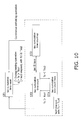
FIG. 10 is a flowchart showing the steps for determining that the heat storage operation has ended; -
FIG. 11 is a flowchart showing the heat retention operation after the heat storage operation; -
FIG. 12 is a flowchart showing correction of the opening degree of the heat storage expansion valve in the heat storage operation during the heat storage operation, in the air conditioning apparatus according tomodification 2; -
FIG. 13 is a flowchart showing restriction of heating capacity of the indoor heat exchanger during the heat storage operation in the air conditioning apparatus according to modification 3; -
FIG. 14 is a flowchart showing the heat retention operation after the heat storage operation in the air conditioning apparatus according to modification 4; and -
FIG. 15 is a flowchart showing recommencement of the heat storage operation after the heat storage operation in the air conditioning apparatus according to modification 5. - The embodiments of the air conditioning apparatus according to the present invention will now be described with reference to the drawings. Note that the basic configuration of the air conditioning apparatus according to the present invention in the embodiments and modifications hereinbelow is illustrative and not restrictive. It is therefore understood that numerous modifications and variations can be devised without departing from the scope of the invention.
-
FIG. 1 shows a schematic structural diagram of theair conditioning apparatus 1 according to an embodiment of the present invention. Theair conditioning apparatus 1 is a device used for air conditioning inside a building for example, by performing a vapor compression type refrigerant cycle. Theair conditioning apparatus 1 comprises primarily anoutdoor unit 2 connected to a plurality (in this case, two) ofindoor units outdoor unit 2 and the plurality ofindoor units refrigerant communication pipe 6 and a gasrefrigerant communication pipe 7. That is, the vapor compressiontype refrigerant circuit 10 of theair conditioning apparatus 1 is configured such that theoutdoor unit 2 and the plurality ofindoor units refrigerant communication pipes - The
indoor units indoor units outdoor unit 2 via therefrigerant communication pipes refrigerant circuit 10. - The configuration of the
indoor units indoor unit 4b has the same configuration as that of theindoor unit 4a, only the configuration of theindoor unit 4a is described below, and the configuration of each part of theindoor unit 4b is omitted, it being understood that the character "a" indicating the respective parts of theindoor unit 4a, would be replaced by the character "b" in the case of theindoor unit 4b. - The
indoor unit 4a has primarily anindoor refrigerant circuit 10a (in the case of theindoor unit 4b, anindoor refrigerant circuit 10b), comprising a part of therefrigerant circuit 10. Theindoor refrigerant circuit 10a has primarily anindoor expansion valve 41a and anindoor heat exchanger 42a. - The
indoor expansion valve 41a is a valve that depressurizes the refrigerant flowing in theindoor refrigerant circuit 10a and varies the quantity of refrigerant flowing into theindoor heat exchanger 42a. Theindoor expansion valve 41a is an electronic expansion valve connected at the side of theindoor heat exchanger 42a to which the liquid refrigerant flows (the liquid-side). - For example, the
indoor heat exchanger 42a is formed as a cross fin type, fin and tube heat exchanger. Anindoor fan 43a for directing indoor air to theindoor heat exchanger 42a is disposed in the vicinity of theindoor heat exchanger 42a. As indoor air is delivered to theindoor heat exchanger 42a by theindoor fan 43a, theindoor heat exchanger 42a exchanges heat between the refrigerant and the indoor air. The rotations of theindoor fan 43a are driven by anindoor fan motor 44a. Thus theindoor heat exchanger 42a comes to function as a radiator of the refrigerant or as an evaporator of the refrigerant. - Further, various kinds of sensors are provided to the
indoor unit 4a. A liquid-side temperature sensor 45a for detecting the temperature Trla of refrigerant in a liquid state or a gas-liquid two-phase state is provided at the liquid-side of theindoor heat exchanger 42a. At the side of theindoor heat exchanger 42a to which the gas refrigerant flows (the gas-side), is provided a gas-side temperature sensor 46a for detecting the temperature Trga of refrigerant in a gaseous state. Anindoor temperature sensor 47a for detecting the temperature (the indoor temperature Tra) of indoor air in the area of air relevant to theindoor unit 4a, is provided to the side of theindoor unit 4a on which the intake side for indoor air is positioned. Further, theindoor unit 4a has an indoor-side control part 48a for controlling the operation of each part comprising theindoor unit 4a. The indoor-side control part 48a has a microcomputer or memory or the like provided for performing control of theindoor unit 4a, and is capable of exchanging control signals and the like with aremote controller 49a to facilitate individual operation of theindoor unit 4a, and exchanging control signals and the like with theoutdoor unit 2. Theremote controller 49a is a device operated by a user for issuing instructions to operate or stop operation of the air conditioning apparatus or to implement various kinds of settings related to air conditioning operations. - The
outdoor unit 2 is installed outdoors. Theoutdoor unit 2 is connected to theindoor units refrigerant communication pipes refrigerant circuit 10. - The configuration of the
outdoor unit 2 will now be described. - The
outdoor unit 2 has primarily an outdoor-side refrigerant circuit 10c that comprises a part of therefrigerant circuit 10. This outdoor-side refrigerant circuit 10c has primarily, acompressor 21, afirst switching mechanism 22, anoutdoor heat exchanger 23, anoutdoor expansion valve 24, asecond switching mechanism 27, a stored-heat heat exchanger 28, and a heat storage expansion valve 29. - The
compressor 21 is a hermetically sealed compressor accommodating compression elements in a casing not shown in the drawing and acompressor motor 20 that drives the rotation of the compression elements. Thecompressor motor 20 is capable of being supplied with power via an inverter device not shown in the drawing, and the operating capacity of thecompressor motor 20 is able to be varied as the frequency (that is, the rotational speed) of the inverter device is caused to change. - The
first switching mechanism 22 is a four-way switching valve for switching the direction of the flow of the refrigerant. When thefirst switching mechanism 22 causes theoutdoor heat exchanger 23 to function as a radiator of the refrigerant, thefirst switching mechanism 22 performs a switch that connects the discharge side of thecompressor 21 and the gas-side of theoutdoor heat exchanger 23, and connects the gas-side of the stored-heat heat exchanger 28 and the intake side of the compressor 21 (refer to the solid line of thefirst switching mechanism 22 inFIG. 1 , outdoor heat release switch condition). Here, when thefirst switching mechanism 22 is switched to the outdoor heat release switch condition, the stored-heat heat exchanger 28 can be caused to function as an evaporator of the refrigerant. Further, when thefirst switching mechanism 22 causes theoutdoor heat exchanger 23 to function as an evaporator of the refrigerant, thefirst switching mechanism 22 performs a switch that connects the intake side of thecompressor 21 and the gas-side of theoutdoor heat exchanger 23, and connects the gas-side of the stored-heat heat exchanger 28 and the discharge side of the compressor 21 (refer to the broken line of thefirst switching mechanism 22 inFIG. 1 , outdoor evaporation switch condition). Here, when thefirst switching mechanism 22 is switched to the outdoor evaporation switch condition, the stored-heat heat exchanger 28 can be caused to function as a radiator of the refrigerant. Note that it is also suitable for thefirst switching mechanism 22 to be configured so as to perform the same function as a combination of a three-way valve or electromagnetic valve or the like. - The
outdoor heat exchanger 23 is formed for example from a cross fin type, fin and tube heat exchanger. Anoutdoor fan 25 for directing external air to theoutdoor heat exchanger 23 is installed in the vicinity of theoutdoor heat exchanger 23. As external air is delivered to theoutdoor heat exchanger 23 by theoutdoor fan 25, theoutdoor heat exchanger 23 exchanges heat between the refrigerant and the external air. The rotations of theoutdoor fan 25 are driven by anoutdoor fan motor 26. Thus theoutdoor heat exchanger 23 comes to function as a radiator of the refrigerant or as an evaporator of the refrigerant. - The
outdoor expansion valve 24 depressurizes the refrigerant that flows to theoutdoor heat exchanger 23 of the refrigerant in the outdoor-side refrigerant circuit 10c, and is a valve that can vary the quantity of refrigerant flowing into theoutdoor heat exchanger 23. Theoutdoor expansion valve 24 is an electronic expansion valve connected at the liquid side of theoutdoor heat exchanger 23. - The
second switching mechanism 27 is a four-way switching valve for switching the direction of the flow of the refrigerant. When thesecond switching mechanism 27 causes theindoor heat exchangers second switching mechanism 27 performs a switch that connects the intake side of thecompressor 21 and the refrigerant communication pipe 7 (refer to the solid line of thesecond switching mechanism 27 inFIG. 1 , indoor evaporation condition switch). Further, when thesecond switching mechanism 27 causes theindoor heat exchangers second switching mechanism 27 performs a switch that connects the discharge side of thecompressor 21 and the refrigerant communication pipe 7 (refer to the broken line of thesecond switching mechanism 27 inFIG. 1 , indoor heat release switch condition). Here, one of the ports from among the four ports of the second switching mechanism 27 (the port toward the right of the page inFIG. 1 ), being continuously connected to the port connected to the intake side of the compressor 21 (the upper port on the page inFIG. 1 ) via acapillary tube 271, is effectively not used. Note that it is also suitable for thesecond switching mechanism 27 to be configured so as to perform the same function as a combination of a three-way valve or electromagnetic valve or the like. - The stored-
heat heat exchanger 28 is a heat exchanger that exchanges heat between the refrigerant and the heat storage material. The stored-heat heat exchanger 28, while storing heat to the heat storage material when caused to function as a radiator for the refrigerant, by being caused to function as an evaporator of the refrigerant, is used for performing heat release from the heat storage material (stored-heat usage). The stored-heat heat exchanger 28 has primarily aheat storage tank 281 in which the heat storage material is stored and a heat-transfer tube group 282 arranged so as to be immersed in the heat storage material. Here, as shown inFIG. 2 , theheat storage tank 281 is a box having a substantially rectangular parallelepiped shape, inside of which the heat storage material is stored. Here a substance that facilitates heat storage through phase change is used as the heat storage material. Specifically, the heat storage material used is for example polyethylene glycol, sodium sulfate hydrate or paraffin or the like, having a phase change temperature of 30°C-40°C, such that phase change (melting) stores heat when the stored-heat heat exchanger 28 is used as a radiator for the refrigerant, and phase change (coagulation) uses stored heat when the stored-heat heat exchanger 28 is used as an evaporator of refrigerant. As shown inFIG. 2 , the heat-transfer tube group 282 has a configuration in which a plurality of heat-transfer tubes 285 are branched and connected via aheader pipe 283 and adistributor 284 provided at the refrigerant outlet and inlet. Here, each of the plurality of heat-transfer tubes 285 is of a form folding up and down, the heat-transfer tube group being formed by the connection of the ends of the plurality of heat-transfer tubes 285 to thedistributor 284 and theheader pipe 283. The gas-side of the stored-heat heat exchanger 28 (that is one end of the heat-transfer tube group) is connected to thefirst switching mechanism 22, while the liquid-side of the stored-heat heat exchanger 28 (that is the other end of the heat-transfer tube group 282) is connected via the heat storage expansion valve 29 to the portion between therefrigerant communication pipe 6 and theoutdoor expansion valve 24 of the refrigerant circuit 10 (the outdoor-side refrigerant circuit 10c).FIG. 2 shows a schematic structural diagram of the stored-heat heat exchanger 28. - The heat storage expansion valve 29 is a valve that depressurizes the refrigerant that flows through the stored-
heat heat exchanger 28 of the refrigerant in the outdoor-side refrigerant circuit 10c, and varies the quantity of the flow of the refrigerant to the stored-heat heat exchanger 28. The heat storage expansion valve 29 is an electronic expansion valve connected to the liquid side of the stored-heat heat exchanger 28. - Various kinds of sensors are provided in the
outdoor unit 2. In theoutdoor unit 2 are installed, anintake pressure sensor 31 for detecting the intake pressure Ps of thecompressor 21, adischarge pressure sensor 32 for detecting the discharge pressure Pd of thecompressor 21, anintake temperature sensor 33 for detecting the intake temperature Ts of thecompressor 21 and adischarge temperature sensor 34 for detecting the discharge temperature Td of thecompressor 21. An outdoor heatexchange temperature sensor 35 for detecting the temperature Toll of refrigerant in a gas-liquid two-phase state is installed to theoutdoor heat exchanger 23. To the liquid-side of theoutdoor heat exchanger 23, a liquid-side temperature sensor 36 for detecting the temperature Tol2 of refrigerant in a liquid state or a gas-liquid two-phase state is installed. An externalair temperature sensor 37 for detecting the temperature (that is the outdoor temperature Ta) of the external air in the outdoor space in which the outdoor unit 2 (that is theoutdoor heat exchanger 23 or the stored-heat heat exchanger 28) is arranged, is provided to the external air intake side of theoutdoor unit 2. Further, theoutdoor unit 2 has an outdoor-side control part 38 for controlling the operation of each part comprising theoutdoor unit 2. The outdoor-side control part 38 has a microcomputer or memory provided for controlling theoutdoor unit 2 and an inverter device or the like for controlling thecompressor motor 25, and is thus able to exchange control signals and the like with the indoor-side control parts indoor units - The
refrigerant communication pipes air conditioning apparatus 1 is installed, and can be of various lengths and diameters depending on the installation conditions of theoutdoor unit 2 and theindoor units - As shown in
FIG. 1 , theremote controllers indoor units side control parts indoor units side control part 38 of theoutdoor unit 2 comprise the control part 8 that performs operation control of the entireair conditioning apparatus 1. As shown inFIG. 3 , the control part 8 is connected so as to be capable of receiving detection signals of each of the sensors 31-37, 45a, 45b, 46a, 46b, 47a and 48b etc. The control part 8, is configured so as to be capable of performing air conditioning operations (cooling operation and heating operation) by controlling each of the devices andvalves FIG. 3 shows a control block diagram of theair conditioning apparatus 1. - As described above, the
air conditioning apparatus 1 has therefrigerant circuit 10 configured by the connection of the plurality (in this case, two) of theindoor units outdoor unit 2. In theair conditioning apparatus 1 the operation controls described below are performed by the control part 8. - The basic operations of the cooling operation, the heating operation, the heat storage operation and the defrosting operation of the
air conditioning apparatus 1 will now be described with reference toFIGS. 4 through 9 . Here,FIG. 4 shows the flow of refrigerant in the refrigerant circuit in the cooling operation.FIG. 5 shows the flow of refrigerant in the refrigerant circuit in the heating operation.FIG. 6 shows the flow of refrigerant in the refrigerant circuit in the heat storage operation (heat storage operation during the heating operation).FIGS. 7 through 9 show the flow of refrigerant in the refrigerant circuit for the defrosting operation (stored-heat usage operation during the defrosting operation). - When an instruction for the cooling operation is issued from the
remote controllers first switching mechanism 22 switches to implement the outdoor heat release switch condition (the condition indicated by the solid line of thefirst switching mechanism 22 inFIG. 4 ), and thesecond switching mechanism 27 switches to implement the indoor evaporation condition switch (the condition indicated by the solid line of thesecond switching mechanism 27 inFIG. 4 ), the heat storage expansion valve 29 is put into the closed condition (that is, the condition in which the stored-heat heat exchanger 28 is not used), and thecompressor 21, theoutdoor fan 25, and theindoor fans 43a - Now, the low-pressure gas refrigerant inside the
refrigerant circuit 10 is taken into thecompressor 21 and compressed, becoming high-pressure gas refrigerant. This high-pressure gas refrigerant is delivered to theoutdoor heat exchanger 23 via thefirst switching mechanism 22. The high-pressure gas refrigerant delivered to theoutdoor heat exchanger 23 is condensed through being cooled by heat exchange with external air supplied by theoutdoor fan 25, in theoutdoor heat exchanger 23 functioning as a radiator of the refrigerant, becoming high-pressure liquid refrigerant. This high-pressure liquid refrigerant is delivered from theoutdoor unit 2 to theindoor units outdoor expansion valve 24 and therefrigerant communication pipe 6. - The high-pressure refrigerant delivered to the
indoor units indoor expansion valves indoor heat exchangers indoor heat exchangers indoor fans indoor heat exchangers indoor units outdoor unit 2 via therefrigerant communication pipe 7. - The low-pressure gas refrigerant delivered to the
outdoor unit 2 is again taken into thecompressor 21 via thesecond switching mechanism 27. - When an instruction for the heating operation is issued from the
remote controllers first switching mechanism 22 switches to implement the outdoor evaporation switch condition (the condition indicated by the broken line of thefirst switching mechanism 22 inFIG. 5 ), and thesecond switching mechanism 27 switches to implement the indoor heat release switch condition (the condition indicated by the broken line of thesecond switching mechanism 27 inFIG. 5 ), the heat storage expansion valve 29 is put into the closed condition (that is, the condition in which the stored-heat heat exchanger 28 is not used), and thecompressor 21, theoutdoor fan 25, and theindoor fans 43a - Now, the low-pressure gas refrigerant inside the
refrigerant circuit 10 is taken into thecompressor 21 and compressed, becoming high-pressure gas refrigerant. This high-pressure gas refrigerant is delivered from theoutdoor unit 2 to theindoor units second switching mechanism 27 and therefrigerant communication pipe 7. - The high-pressure gas refrigerant delivered to the
indoor units indoor heat exchangers indoor fans 43aindoor heat exchangers indoor expansion valves indoor expansion valves indoor units outdoor unit 2 via therefrigerant communication pipe 7. - The refrigerant delivered to the
outdoor unit 2 is then delivered to theoutdoor expansion valve 24 where it is depressurized, becoming low-pressure refrigerant in a gas-liquid two-phase state, which is then delivered to theoutdoor heat exchanger 23, wherein this refrigerant is evaporated by being heated through heat exchange with external air supplied by theoutdoor fan 25, in theoutdoor heat exchanger 23 functioning as an evaporator of the refrigerant, to become low-pressure gas refrigerant. The low-pressure gas refrigerant is again taken into thecompressor 21 via thefirst switching mechanism 22. - During the heating operation, the heat storage operation is performed that stores heat to the heat storage material by causing the stored-
heat heat exchanger 28 to function as a radiator of the refrigerant. That is, during the heating operation in which theoutdoor heat exchanger 23 is caused to function as an evaporator of the refrigerant, moreover theindoor heat exchangers heat heat exchanger 28 to function as a radiator of the refrigerant. This heat storage operation during the heating operation is performed through opening of the heat storage expansion valve 29, with the switchingmechanisms FIG. 6 ). - Here, the low-pressure gas refrigerant inside the
refrigerant circuit 10 is taken into thecompressor 21 and compressed, becoming high-pressure gas refrigerant. Part of this high-pressure gas refrigerant, in the same manner as applies during the heating operation, is delivered to theindoor units outdoor unit 2 via thesecond switching mechanism 27 and therefrigerant communication pipe 7. This high-pressure gas refrigerant delivered to theindoor units indoor fans indoor heat exchangers indoor expansion valves indoor expansion valves indoor units outdoor unit 2 via therefrigerant communication pipe 7. - Further, the remaining high pressure gas refrigerant discharged from the
compressor 21 is delivered, via thefirst switching mechanism 22 to the stored-heat heat exchanger 28, where this refrigerant is condensed by cooling performed through heat exchange with the heat storage material in the stored-heat heat exchanger 28 functioning as a radiator of the refrigerant, becoming high-pressure liquid refrigerant. This high-pressure liquid refrigerant is depressurized by the expansion valve 29. Here, the heat storage material of the stored-heat heat exchanger 28 stores heat by phase change (melting) through being heated by heat exchange with the refrigerant. - The refrigerant depressurized at the heat storage expansion valve 29 then merges with the refrigerant delivered from the
indoor units outdoor unit 2, the merged flow then being delivered to theoutdoor expansion valve 24 where the refrigerant is depressurized, becoming low-pressure refrigerant in a gas-liquid two-phase state. This low-pressure refrigerant in a gas-liquid two-phase state is delivered to theoutdoor heat exchanger 23 where the refrigerant is evaporated by being heated through performance of heat exchange with external air supplied by theoutdoor fan 25, in theoutdoor heat exchanger 23 functioning as an evaporator of the refrigerant, becoming low-pressure gas refrigerant. This low-pressure gas refrigerant is then taken into thecompressor 21 again, via thefirst switching mechanism 22. In this way, in the heat storage operation during the heating operation, the stored-heat heat exchanger 28 is able to function in parallel with theindoor heat exchangers refrigerant circuit 10 is configured such that, in the heat storage operation during the heating operation, the high-pressure gas refrigerant discharged from thecompressor 21 can be delivered to theindoor heat exchangers heat heat exchanger 28 in parallel. - During the heating operation, the defrosting operation that performs defrosting of the heat exchanger is carried out, by causing the
outdoor heat exchanger 23 to function as a radiator of the refrigerant. During the defrosting operation, the stored-heat usage operation is performed that releases heat from the heat storage material, by causing the stored-heat heat exchanger 28 to function as an evaporator of the refrigerant. That is, the stored-heat usage operation (stored-heat usage operation during the defrosting operation, defrosting operation with stored-heat usage operation) is performed in which theoutdoor heat exchanger 23 is caused to function as a radiator of the refrigerant, moreover the stored-heat heat exchanger 28 is caused to function as an evaporator of the refrigerant. Further, here, the heating operation is also performed simultaneously, by causing theindoor heat exchangers switching mechanism 22 switching to implement the outdoor heat release switch condition, moreover thesecond switching mechanism 27 switching to implement the indoor heat release switch condition (referFIG. 7 ). Further, during the defrosting operation theoutdoor fan 25 is stopped. - Here, the low-pressure gas refrigerant inside the
refrigerant circuit 10 is taken into thecompressor 21 and compressed, becoming high-pressure gas refrigerant. Part of this high-pressure gas refrigerant, in the same manner as applies during the heating operation, is delivered to theindoor units outdoor unit 2 via thesecond switching mechanism 27 and therefrigerant communication pipe 7. This high-pressure gas refrigerant delivered to theindoor units indoor fans indoor heat exchangers indoor expansion valves indoor units outdoor unit 2 via therefrigerant communication pipe 7. - Further, the remaining high pressure gas refrigerant discharged from the
compressor 21 is delivered via thefirst switching mechanism 22, to theoutdoor heat exchanger 23, to be cooled by heat exchange with frost or ice adhering to theoutdoor heat exchanger 23 functioning as a radiator of the refrigerant. This high-pressure refrigerant is depressurized by theoutdoor expansion valve 24. Here, the frost or ice adhering to theoutdoor heat exchanger 23 is melted by being heated through heat exchange with the refrigerant, such that defrosting of theoutdoor heat exchanger 23 is performed. - The high-pressure refrigerant depressurized by the
outdoor expansion valve 24, then merges with the refrigerant delivered from theindoor units outdoor unit 2, the merged flow then being delivered to the heat storage expansion valve 29 where the refrigerant is depressurized, becoming low-pressure refrigerant in a gas-liquid two-phase state. This low-pressure refrigerant in a gas-liquid two-phase state is delivered to the stored-heat heat exchanger 28 where the refrigerant is evaporated by being heated through heat exchange with the heat storage material, in the stored-heat heat exchanger 28 functioning as an evaporator of the refrigerant, becoming low-pressure gas refrigerant. This low-pressure gas refrigerant is then taken into thecompressor 21 again, via thefirst switching mechanism 22. The heat storage material of the stored-heat heat exchanger 28 undergoes phase change (coagulation) through being cooled by heat exchange with the refrigerant, stored heat being used. In this way, when in the stored-heat usage operation during the defrosting operation (or the defrosting operation with stored-heat usage operation) the heating operation is performed simultaneously, theindoor heat exchangers outdoor heat exchanger 23. That is, therefrigerant circuit 10 is configured such that when, in the stored-heat usage operation during the defrosting operation (or the defrosting operation with stored-heat usage operation) the heating operation is performed simultaneously, the high-pressure gas refrigerant discharged from thecompressor 21 can be delivered to theoutdoor heat exchanger 23 and theindoor heat exchangers - Further, the defrosting operation with stored-heat usage operation is not restricted to the above description (refer
FIG. 7 ) and it is also suitable for theoutdoor heat exchanger 23 to be caused to function as a radiator of the refrigerant, moreover for the stored-heat exchanger 28 to be caused to function as an evaporator of the refrigerant. For example, it is suitable to have theindoor expansion valves FIG. 8 ), or, by switching thesecond switching mechanism 27 to the indoor evaporation switch condition, to cause theindoor heat exchangers FIG 9 ). - In the above mentioned cooling operation, the control part 8 implements control by determining the opening degree of each of the
indoor expansion valves indoor heat exchangers intake pressure sensor 31, and the temperatures Trga, Trgb of the refrigerant at the gas-side of theindoor heat exchangers side temperature sensors indoor expansion valves indoor heat exchangers compressor 21, in the cooling operation. Moreover, the superheating degrees SHra, SHrb are obtained by deducting the evaporation temperature Te from the temperatures Trga and Trgb of refrigerant at the gas-side of the respectiveindoor heat exchangers - Note that in the cooling operation, control of each device of the
indoor units indoor 41b, is performed by the indoor-expansion valves 41aside control parts indoor unit 2 including theoutdoor expansion valve 24 is performed by the outdoor-site control part 38 of the control part 8. - In the above mentioned heating operation, the control part 8 implements control by determining the opening degree of each of the
indoor expansion valves indoor heat exchangers discharge pressure sensor 32, and the temperatures Trla, Trlb of the refrigerant at the liquid-side of theindoor heat exchangers side temperature sensors compressor 21 via theindoor heat exchangers indoor expansion valves indoor heat exchangers - Note that in the heating operation, control of each device of the
indoor units indoor 41b, is performed by the indoor-expansion valves 41aside control parts indoor unit 2 including theoutdoor expansion valve 24 is performed by the outdoor-site control part 38 of the control part 8. - In the above mentioned defrosting operation, in the case that the outdoor heat exchanger outlet temperature Tol2 that is the temperature of the refrigerant at the outlet of the
outdoor heat exchanger 23 is greater than or equal to a predetermined defrosting operation finish temperature Tdefe, or the case that a predetermined defrosting operation time tdefe has elapsed, the defrosting operation is ended and the heating operation or heat storage operation during the heating operation is transitioned to. - As described above, the
air conditioning apparatus 1 is able to switch between performing the cooling operation and the heating operation. By performing the heat storage operation during the heating operation, heat is stored to the heat storage material while the heating operation continues, and by performing the stored-heat usage operation during the defrosting operation, the defrosting operation can be performed while utilizing stored heat of the heat storage material. - The above mentioned heat storage operation (including the heating operation after the heat storage operation) has contrive for control as follows.
- In the above mentioned heat storage operation, the quantity of refrigerant flowing into the stored-
heat heat exchanger 28 must be maintained through controlling the opening degree of the heat storage expansion valve 29. However, when control of the opening degree of the heat storage expansion valve 29 involves controlling the subcooling degree using the heat storage expansion valve 29 as inpatent document 1, in the case in which it is not possible to sufficiently maintain the quantity of refrigerant flowing into the stored-heat heat exchanger 28 during the heat storage operation, there is concern of an insufficiency of heat being stored to the heat storage material notwithstanding that the heat storage operation has ended. - Thus, in the heat storage operation, the opening degree of the heat storage expansion valve 29 is controlled, as shown in
formula 1, to be the setting heat storage operation opening degree MVacs determined by a function based on the condensation pressure Pc that is the saturation pressure equivalent to the condensation temperature Tc of refrigerant in therefrigerant circuit 10, the liquid pipe pressure P1 that is the pressure of the refrigerant in the outlet of the heat storage expansion valve 29, and the enthalpy hi, ho of the refrigerant at the inlet and the outlet of the stored-heat heat exchanger 28.
-
Formula 1 describes the characteristics of the flow quantity of the refrigerant in the expansion valve 29. k1, k2 are coefficients. CVac is a flow coefficient of the expansion valve 29. - The flow coefficient of the heat storage expansion valve 29 CVac, is expressed in
formula 2.
- Here, k3 is the coefficient corresponding to the heat storage capacity of the heat storage material. Δh is the enthalpy difference of the refrigerant in the outlet and inlet of the stored-
heat heat exchanger 28, as expressed in formula 3.
- Here, hi is the enthalpy of refrigerant in the inlet of the stored-heat heat exchanger 28 (the gas-side of the stored-heat heat exchanger 28), and ho is the enthalpy of the refrigerant in the outlet of the stored-heat heat exchanger 28 (the liquid-side of the stored-heat heat exchanger 28). The inlet enthalpy hi uses an enthalpy of the refrigerant envisaging the case in which the superheating degree of the refrigerant in the inlet of the stored-
heat heat exchanger 28 for the condensation pressure Pc is the superheating degree of the refrigerant (for example, 10°C) used for setting the opening degree. The outlet enthalpy ho uses an enthalpy of the refrigerant envisaging the case in which the subcooling degree of the refrigerant in the outlet of the stored-heat heat exchanger 28 for the condensation pressure Pc is the subcooling degree of the refrigerant (for example, 3°C) used for setting the opening degree. Note that when temperature sensors are installed to the outlet of the stored-heat heat exchanger 28, it is suitable to use the temperature detected by these temperature sensors to obtain the enthalpy of refrigerant in the inlet and the outlet of the stored-heat heat exchanger 28. - Further, in
formula 2, ΔP is the pressure difference corresponding to the pressure differential of the heat storage expansion valve 29, expressed by formula 4.
- Here, Pc is the condensation pressure. P1 is the liquid pipe pressure corresponding to the pressure of the refrigerant at the outlet side of the heat storage expansion valve 29, here, expressed by the following formula 5 derived from the function of condensation pressure Pc.

- Here, k4-k6 are coefficients. In the case in which a pressure sensor is provided to the outlet of the heat storage expansion valve 29, it is suitable to use the pressure value as detected by this pressure sensor for the liquid pipe pressure.
- Further, SLD in
formula 2 is the density of the refrigerant in the outlet of the stored-heat heat exchanger 28. The value for the density of refrigerant used envisages the case in which the subcooling degree of the refrigerant in the outlet of the stored-heat heat exchanger 28 for the condensation pressure Pc is the subcooling degree of the refrigerant (for example, 3°C) used for setting the opening degree. Note that in the case in which a temperature sensor is provided to the outlet of the stored-heat heat exchanger 28, it is suitable to use the temperature value detected by this temperature sensor to obtain the density of refrigerant in the outlet of the stored-heat heat exchanger 28. - Thus, obtaining the liquid pipe pressure P1 from the condensation pressure Pc and formula 5, it is possible to obtain the pressure difference ΔP from the liquid pipe pressure P1 and formula 4. Further, obtaining the density SLD and the enthalpy hi and ho of the refrigerant in the outlet and inlet of the stored-
heat heat exchanger 28 from the condensation pressure Pc, it is possible to obtain the enthalpy difference Δ h from the enthalpy hi, ho and formula 3. Moreover, obtaining the flow quantity coefficient CVac of the heat storage expansion valve 29 from enthalpy difference Δh, the pressure differential ΔP, SLD, andformula 2, it is possible to obtain the setting heat storage operation opening degree MVacs from the flow coefficient CVac andformula 1. Then, during the heat storage operation, the opening degree of the heat storage expansion valve 29 can be controlled so as to be the setting heat storage operation opening degree MVacs. - Thus in the heat storage operation the opening degree of the heat storage expansion valve 29 is controlled so as to be the setting heat storage operation opening degree MVacs, determined by the function based on the condensation pressure Pc, the liquid pipe pressure P1 and the enthalpy hi, ho of the refrigerant in the inlet and the outlet of the stored-
heat heat exchanger 28. Accordingly, the plurality of state quantities of the refrigerant related to the stored-heat heat exchanger 28 come to be reflected in the determination of the opening degree of the heat storage expansion valve 29, and the opening degree of the heat storage expansion valve 29 during the heat storage operation can be made an opening degree that enables the flow quantity of refrigerant to the stored-heat heat exchanger 28 to be sufficiently maintained. - Thus the opening degree of the heat storage expansion valve 29 during the heat storage operation is appropriately controlled, and the occurrence of insufficiency of heat storage to the heat storage material when the heat storage operation has ended can be suppressed.
- Further, the density SLD of the refrigerant in the outlet of the stored-
heat heat exchanger 28 can also be used in the function for determining the setting heat storage operation opening degree MVacs. The density SLD of the refrigerant in the outlet of the stored-heat heat exchanger 28 that is one of the state quantities of the refrigerant related to the stored-heat heat exchanger 28 comes to be reflected in the determination of the opening degree of the heat storage expansion valve 29, enabling the opening degree of the heat storage expansion valve 29 during the heat storage operation to be controlled more appropriately. - Further, it is preferable that the timing of when the above-mentioned heat storage operation has finished is judged appropriately after ascertaining whether heat storage to the heat storage material has been sufficiently performed. However here, as heat storage material that undergoes phase change is used, there being little temperature difference in the heat storage material during phase change and after phase change, and the heat-
transfer tubes 285 comprising the stored-heat heat exchanger 28 being densely arranged in consideration of the thermal conductivity being small, therefore appropriately determining the timing of the ending of the heat storage operation is difficult. - Thus in the heat storage operation during the heating operation, when the heat storage cumulative time tac that is the integrated value for the time which the condensation temperature Tc of the refrigerant in the
refrigerant circuit 10 is greater than or equal to a first heat storage condensation temperature Tcc1 as the heat storage completion condensation temperature, is greater than or equal to the heat storage completion cumulative time tace, the heat storage operation is ended. - Specifically here, judging that the heat storage operation ended is performed in accordance with steps ST1-ST4 as shown in the flowchart of
FIG. 10 . - Once the heat storage operation starts, firstly at step ST1, the time accumulating the heat storage cumulative time tac is reset.
- In the case that the heat storage operation satisfies the heat storage time count commencement conditions, the processes of step ST2 are transitioned to, and the counting of the time accumulating the heat storage cumulative time tac commences. Here, the heat storage time count commencement conditions are the conditions for judging whether the condition is that heat storage to the heat storage material is in effect performed. The heat storage time count commencement conditions are satisfied when, the heat storage operation is performed during the heating operation, moreover, the condensation temperature Tc is higher than a prescribed first heat storage condensation temperature Tcc1 (here, a temperature higher than the phase change temperature of the heat storage material, for example 41°C), moreover the condensation temperature Tc is greater than or equal to a second heat storage condensation temperature Tcc2 that is slightly less than the first heat storage condensation temperature Tcc1 (here, substantially the same temperature as the phase change temperature of the heat storage material, for example 35°C) for a duration that continues beyond a predetermined time tac2 (for example 10 minutes).
- Further, in the case that the heat storage time count finish condition is satisfied, this condition being that the heat storage cumulative time tac from commencement of the counting of time accumulating the heat storage cumulative time tac at step ST2 is greater than or equal to the predetermined heat storage completion cumulative time tace, the processes of step ST3 are transitioned to, the counting of time accumulating the heat storage cumulative time tac ends (count up) and the heat storage operation finishes.
- After counting of the time accumulating the heat storage cumulative time tac has commenced at step ST2, in the case in which the heat storage operation satisfies the heat storage time hold condition, step ST4 is transitioned to, and the counting of the time accumulating the heat storage cumulative time tac is interrupted (put on hold). Here, the heat storage time hold condition is the condition for judging whether it cannot be said that heat storage to the heat storage material is in effect performed. Here, the heat storage time hold condition is satisfied when the condensation temperature Tc is less than a third heat storage condensation temperature Tcc3 that is slightly lower than the first heat storage condensation temperature Tcc1 (here, the temperature between the first heat storage condensation temperature Tcc1 and the second heat storage condensation temperature Tcc2, for example 40°C).
- Moreover after the time count accumulating heat storage cumulative time tac is interrupted at step ST4, in the case in which the heat storage operation satisfies the heat storage time count recommence condition, the processes of step ST2 are returned to, and the time count accumulating the heat storage cumulative time tac is recommenced. Here, the heat storage time count recommence condition is the condition for judging whether there has been a return to the condition in which heat storage to the heat storage material is in effect performed. In the case in which the condensation temperature Tc is higher than the first heat storage condensation temperature Tcc1, the heat storage time count recommence condition is satisfied. In this way, the counting of the time accumulating the heat storage cumulative time tac is performed only when the condensation temperature Tc is greater than or equal to the first heat storage condensation temperature Tcc1, as the heat storage completion condensation temperature.
- Further, after the time count accumulating the heat storage cumulative time tac is interrupted at step ST4, in the case in which the heat storage operation satisfies the heat storage time count reset condition, the processes of step ST1 are returned to, and the time for accumulation of heat storage cumulative time tac is reset. Here, the heat storage time reset condition is the condition for judging whether it is necessary to redo the counting of time accumulating the heat storage cumulative time tac because the condition in which it cannot be said that heat storage to the heat storage material is in effect performed has continued for a long duration. Here, the heat storage time reset condition is satisfied when for a duration that continues beyond a predetermined time tac4 (for example, 15 minutes), the condensation temperature Tc continues to be greater than or equal to a fourth heat storage condensation temperature Tcc4 that is slightly less than the first heat storage condensation temperature Tcc1 (here substantially the same temperature as the heat storage material phase change temperature, for example 35°C). Moreover, in the event that the defrosting operation has commenced, even in the course of the processes of step ST2 and step ST4, a return to the processes of step ST1 is forced, and the time for accumulation of the heat storage cumulative time tac is reset.
- In this way, during the heat storage operation, whether the condition in which heat storage to the heat storage material is in effect performed is judged based on whether the condensation temperature Tc is greater than or equal to the first heat storage condensation temperature Tcc1, as the heat storage completion condensation temperature, and whether this heat storage operation is in effect performed for a sufficient time is judged on whether the heat storage cumulative time tac is greater than or equal to the heat storage completion cumulative time tace. Thus, the timing of the ending of the heat storage operation can be properly judged. When using heat storage material that undergoes phase change, while properly judging the timing of the ending of the heat storage operation may present difficulties, here, a proper judgment of the timing of the end of the heat storage operation can be made as the indicator of judging the heat storage cumulative time tac has been added.
- Further, when the above-mentioned heat storage to the heat storage material by performance of the heat storage operation during the heating operation (refer
FIG. 6 ) is ended, it could be considered that the heat storage operation only is ended, (that is, by closing the heat storage expansion valve 29 such that the refrigerant does not flow into the stored-heat exchanger 28), and only the above-mentioned heating operation (referFIG. 5 ) is to be performed. However, after the heat storage operation during the heating operation ends, simply switching such that only the heating operation is performed engenders concern that heat release of the heat storage material will occur due to the effects of the outdoor air temperature Ta of the outdoor space in which the stored-heat heat exchanger 28 is installed, causing a decrease in the quantity of heat that can be used in the subsequent stored-heat usage operation during the defrosting operation. - Thus here, after the heat storage operation during the heating operation ends, while performing the heating operation, the heat retention operation for retaining heat of the heat storage material can be performed.
- More specifically, the heat retention operation after the heat storage operation is performed in accordance with steps ST5, ST6 shown in the flowchart of
FIG. 11 . That is, at step ST5, if the heat storage operation during the heating operation has ended, (determination that the heat storage operation has ended ofFIG. 10 ), the heat retention operation of step ST6 is transitioned to. The heat retention operation is performed by slightly opening the heat storage expansion valve 29 (taking the opening degree when the heat storage expansion valve 29 is in the fully open condition as 100%, an opening degree of not greater than approximately 15%). - In this way, by performing the heat retention operation after the heat storage operation has ended, a decrease in heat quantity through heat release from the heat storage material occurring after the heat storage operation ends can be compensated for. In this way decrease in the quantity of heat that can be used in the stored-heat usage operation during the defrosting operation can be suppressed. Further, the heat retention operation is performed by slightly opening the heat storage expansion valve 29 to flow a small quantity of the refrigerant to the stored-
heat heat exchanger 28. Accordingly it becomes difficult for the quantity of the refrigerant flowing into theindoor heat exchangers - As described above, by controlling the opening degree of the heat storage expansion valve 29, the heat storage operation is performed while appropriately controlling the opening degree of the heat storage expansion valve 29, and through judging the ending of the heat storage operation and performing the heat retention operation after the heat storage operation as described above, it becomes possible to suppress the decrease in heat quantity that can be used in the stored-heat usage operation during the defrosting operation while properly judging the timing of the ending of the heat storage operation.
- In the above described embodiment, in the case in which the defrosting operation ends normally, that is, in the case in which the defrosting operation ends with the outdoor heat exchanger outlet temperature Tol2 being greater than or equal to the defrosting operation finish temperature Tdefe, it is possible to judge that there has not been an insufficiency in the quantity of heat stored to the heat storage material in the heat storage operation performed prior to the defrosting operation. Thus for the heat storage operation performed after the defrosting operation, it is suitable that the opening degree of the heat storage expansion valve 29 be controlled so as to be the setting heat storage operation opening degree MVacs determined by a function based on the above-mentioned condensation pressure Pc, the liquid pipe pressure P1, and the enthalpy hi, ho of the refrigerant at the inlet and the outlet of the stored-
heat heat exchanger 28. However, in the case that the defrosting operation finishes abnormally, that is, the case in which the defrosting operation ends with the outdoor heat exchanger outlet temperature Tol2 not being greater than or equal to the defrosting operation finish temperature Tdefe, it is possible to judge that an insufficiency has been occurring in the quantity of heat stored to the heat storage material in the heat storage operation performed prior to the defrosting operation. Thus, for the heat storage operation performed after the defrosting operation, when simply controlling the opening degree of the heat storage expansion valve 29 so as to be the setting heat storage operation opening degree MVacs determined by a function based on the condensation pressure Pc, the liquid pipe pressure P1, and the enthalpy hi, ho of the refrigerant at the inlet and the outlet of the stored-heat heat exchanger 28, insufficiency in the quantity of heat stored to the heat storage material may occur again, raising concerns of abnormal completion of the defrosting operation occurring repeatedly. - Thus here, for the heat storage operation after the defrosting operation finishes abnormally as above, the setting heat storage operation opening degree MVacs is corrected so as to be greater than the opening degree of the heat storage operation after the defrosting operation completes normally.
- Specifically here, correction of the setting heat storage operation opening degree MVacs is performed as follows. Here, the opening degree of the heat storage expansion valve 29 is expressed in
formula 6 using setting heat storage operation opening degree MVacs and correction coefficient α. - Formula 6: Opening degree of the heat storage expansion valve = MVacs × α
- When the heat storage operation commences the correction coefficient α for the setting heat storage operation opening degree MVacs is determined. In the case in which the defrosting operation finishes normally, the correction coefficient α = 1, thus the opening degree of the heat storage expansion valve 29 becomes the same as the setting heat storage operation opening degree MVacs (that is, opening degree of the heat storage expansion valve 29 = setting heat storage operation opening degree MVacs ×1). On the other hand, when the defrosting operation finishes abnormally, the correction coefficient is made α ≧ 1.1, thus the opening degree of the heat storage expansion valve 29 becomes at least α times (for example, α ≧ 1.1) the setting heat storage operation opening degree MVacs (that is, opening degree of the heat storage expansion valve 29 = setting heat storage operation opening degree MVacs × α), being greater than the opening degree of the heat storage operation after the defrosting operation finishes normally. By doing this, in the heat storage operation after the defrosting operation finishes abnormally, an insufficiency in the quantity of heat being stored to the heat storage material occurs less readily.
- In this way, by ascertaining whether the defrosting operation performed prior to the heat storage operation finished normally or abnormally, the opening degree of the heat storage expansion valve 29 in the heat storage operation can be controlled as appropriate, enabling repeated occurrence of abnormal completion of the defrosting operation to be suppressed.
- In the above described embodiment and
modification 1, the stored-heat heat exchanger 28, as shown inFIG. 2 , has primarily theheat storage tank 281 in which the heat storage material is stored and the heat-transfer tube group 282 arranged so as to be immersed in the heat storage material. The heat-transfer tube group 282 has a configuration in which a plurality of heat-transfer tubes 285 are branched and connected via aheader pipe 283 and adistributor 284 provided at the refrigerant outlet and inlet. Thus, in the heat storage operation, there is concern that uneven flow of refrigerant may occur between the heat-transfer tubes 285 comprising the heat-transfer tube group 282 of the stored-heat heat exchanger 28. If uneven flow of refrigerant between the heat-transfer tubes 285 occurs, the unevenness occurs to the extent that heat is stored to the heat storage material in theheat storage tank 281, a condition of coexistence arising having the heat-transfer tubes 285 in the vicinity of heat storage material in the condition in which the temperature is higher than the phase change temperature of the heat storage material (that is, the heat-transfer tubes 285 in the vicinity of the heat storage material for which phase change has completed), and the heat-transfer tubes 285 in the vicinity of heat storage material in the condition in which the temperature is lower than the phase change temperature of the heat storage material (that is, the heat-transfer tubes in the vicinity of the heat storage material for which phase change has not completed). In this condition, a phenomenon readily occurs in which the refrigerant in the gas state flows to the heat-transfer tubes 285 in the vicinity of the heat storage material for which phase change has completed, while the liquid refrigerant accumulates in the heat-storage tubes 285 in the vicinity of the heat storage material for which phase change has not completed (a phenomenon of refrigerant accumulating in the stored-heat heat exchanger 28). This phenomenon of refrigerant accumulating in the stored-heat heat exchanger 28 occurs readily because each of the plurality of heat-transfer tubes 285 is of a form folding up and down. Accordingly, uneven flow to the extent that heat is stored to the heat storage material is difficult to be solved, even leading to insufficient heat being stored to the heat storage material when the heat storage operation has finished. - Thus, in the heat storage operation, as described above, each time the normal opening degree heat storage time tacn passes, a correction is applied such that the setting heat storage operation opening degree MVacs increases, for just the duration of the refrigerant discharge opening degree time tacd (that is, regularly).
- Specifically, the setting heat storage operation opening degree MVacs is corrected following steps ST11-ST13 shown in the flow chart of
FIG. 12 . Here,formula 7 shows the opening degree of the heat storage expansion valve 29 using the setting heat storage operation opening degree MVacs and the correction coefficient β.
- At step ST11, when the heat storage operation commences, the correction coefficient P for the setting heat storage operation opening degree MVacs is determined. Firstly, at step ST12, the correction coefficient β = 1, and from this, the opening degree of the heat storage expansion valve 29 becomes the same as the setting heat storage operation opening degree MVacs (that is opening degree of the heat storage expansion valve 29 = the setting heat storage operation opening degree MVacs × 1). Taking correction coefficient β = 1, when the normal opening degree heat storage time tacn has elapsed, at step ST13, correction coefficient β is taken as ≧ 1.5, thus the opening degree of the heat storage expansion valve 29 becomes not less than β (for example, β ≧ 1.5) times the setting heat storage operation opening degree MVacs (that is, opening degree of the heat storage expansion valve 29 = the setting heat storage operation opening degree MVacs × β), becoming greater than the opening degree at step 12. Then, as correction coefficient β ≧ 1.5, when the time in which the opening degree of the refrigerant discharge tacd has elapsed, step ST12 is returned to, becoming correction coefficient β = 1. In this way, in the heat storage operation, each time the normal opening degree heat storage time tacn passes, for just the passing of the refrigerant discharge opening degree time tacd (that is regularly), the setting heat storage operation opening degree MVacs is corrected so as to increase. Doing this enables the liquid refrigerant accumulating in the heat-
transfer tubes 285 in the vicinity of the heat storage material for which phase change has not completed to be regularly discharged at the outlet side of the stored-heat heat exchanger 28. Note that here, immediately after the heat storage operation is commenced, we have correction coefficient β = 1, and thereafter, this becomes correction coefficient β ≧ 1.5, however this is illustrative and not restrictive, and it is also suitable immediately after commencement of the heat storage operation, to make correction coefficient β ≧ 1.5, and thereafter correction coefficient β = 1. - In this way, the occurrence of the phenomena of refrigerant accumulating in the stored-
heat heat exchanger 28 is suppressed, and the unevenness to the extent that heat is stored to the heat storage material can be solved. - Further, in the case of
modification 2 being used in combination with the correction for the setting heat storage operation opening degree MVacs inmodification 1, the opening degree of the heat storage expansion valve 29 uses the setting heat storage operation opening degree MVacs and the correction coefficients a, β as shown in formula 7'.
- In this case, in the heat storage operation, the correction for the setting heat storage operation opening degree MVacs is performed using the correction coefficients α, β, enabling control of the opening degree of the heat storage expansion valve 29 taking account of the phenomenon of refrigerant accumulating in the stored-
heat heat exchanger 28 and the condition in which the defrosting operation has ended. - In the above described embodiment and
modifications heat heat exchanger 28 decreases, heat storage to the heat storage material becoming more difficult. As heat storage to the heat storage material becomes more difficult, the problem of insufficiency of heat stored to the heat storage material when the heat storage operation has finished occurs more readily. - Thus here, in the heat storage operation during the heating operation, the heating capacity of the
indoor heat exchangers - Specifically here, heating capacity restriction of the
indoor heat exchangers FIG. 13 . - Once the heat storage operation during the heating operation commences, firstly, at step ST21 the heat storage capacity of the stored-
heat heat exchanger 28 is maintained by the opening degree of the heat storage expansion valve 29 being controlled so as to be the setting heat storage operation opening degree MVacs determined by the function based on the condensation pressure Pc, the liquid pipe pressure P1 and the enthalpy hi, ho of the refrigerant, (or further, the opening degree as corrected by the correction coefficients α, β). Further, in the same manner as applies when only the heating operation is performed, the heating capacity of theindoor heat exchangers indoor expansion valves indoor heat exchangers indoor heat exchangers side control parts heat heat exchanger 28. - However, if by maintaining the heating capacity of the
indoor heat exchangers heat heat exchanger 28. Thus, during the processes of step ST21, if the subcooling degree restriction conditions are satisfied, step ST22 is transitioned to and the target subcooling degrees SCras, SCrbs (both being generically referred to as SCr) of subcooling degree control by theindoor expansion valves heat heat exchanger 28. The subcooling degree restriction conditions are satisfied when the heat storage operation during the heating operation is performed, moreover the outdoor temperature Ta is less than a predetermined indoor capacity restriction outdoor temperature Tpa (for example, 4°C), moreover the condensation temperature Tc is less than a predetermined first indoor capacity restriction condensation temperature Tpc1 (a temperature higher than the phase change temperature of the heat storage material, for example 41°C), moreover the operating capacity of thecompressor 21 is greater than a predetermined first indoor capacity restriction capacity fp1 (for example, that the frequency of thecompressor 21 is 98% of the maximum frequency). If the subcooling degree restriction conditions are satisfied in the processes of step ST21, the target subcooling degree SCs of subcooling degree control by theindoor expansion valves indoor expansion valves side control part 38, unlike in the case in which the heating operation only is performed. By doing this, the opening degree of theindoor expansion valves indoor heat exchangers heat heat exchanger 28 is able to be increased by just a corresponding extent. - After transitioning from step ST21 to step ST22, if the subcooling degree restriction release conditions are satisfied, the processes of step ST21 are transitioned to, and the target subcooling degree SCrs for subcooling degree control by the
indoor expansion valves heat heat exchanger 28. The subcooling degree restriction release conditions are satisfied when the condensation temperature Tc is greater than a predetermined second indoor capacity restriction condensation temperature Tpc2 (a temperature slightly higher than the first indoor capacity restriction condensation temperature Tpc1, for example 42°C), moreover the operating capacity of thecompressor 21 is less than a predetermined second indoor capacity restriction capacity fp2 (for example, that the frequency of thecompressor 21 is 90% of the maximum frequency), moreover when a predetermined time tp2 from transition to step ST22 (for example, 3 minutes) has elapsed, or when the condensation temperature Tc is higher than a temperature that is higher (here, a temperature sufficiently higher than the phase change temperature of the heat storage material, for example 50°C) just by a predetermined temperature ΔTpc2 (for example, 8°C) than the second indoor capacity restriction condensation temperature Tpc2. If the subcooling degree restriction release conditions are satisfied in the processes of step ST22, the instruction to increase the target subcooling degree SCs for subcooling by theindoor expansion valves indoor expansion valves heat heat exchanger 28, the heating capacity of theindoor heat exchangers - Further, even during the processes of step ST22, in the case that there is insufficient heat storage capacity of the stored-
heat heat exchanger 28 and the indoor fan restriction conditions are satisfied, the processes of step ST23 are transitioned to, and the rotational speed of theindoor fans heat heat exchanger 28. Thus here, the indoor fan restriction conditions are satisfied when the condensation temperature Tc is less than a predetermined third condensation temperature for indoor capacity restriction Tpc3 (a temperature slightly higher than the phase change temperature of the heat storage material, for example 41°C), moreover a predetermined time tp3 from transition to step ST22 (for example, 5 minutes) has elapsed, moreover the operating capacity of thecompressor 21 is greater than a predetermined third indoor capacity restriction capacity fp3 (for example, that the frequency of thecompressor 21 is 98% of the maximum frequency). Then if the indoor fan restriction conditions are satisfied during the processes of step ST22, the rotational speed of theindoor fans indoor fans indoor fans side control part 38, unlike in the case in which the heating operation only is performed. By doing this, heat exchange in theindoor heat exchangers indoor heat exchangers heat heat exchanger 28 is able to be increased by just a corresponding extent. - After the transition from step ST22 to step ST23, if the indoor fan restriction release conditions are satisfied, the processes of step ST22 are transitioned to, and the rotational speed of the
indoor fans heat heat exchanger 28. The indoor fan restriction release conditions are satisfied when the condensation temperature Tc is greater than a predetermined fourth condensation temperature for indoor capacity restriction Tpc4 (a temperature slightly higher than the first indoor capacity restriction condensation temperature Tpc1, for example 42°C), moreover the operating capacity of thecompressor 21 is less than a predetermined fourth indoor capacity restriction capacity fp4 (for example, that the frequency of thecompressor 21 is 90% of the maximum frequency), moreover when a predetermined time tp4 from transition to step ST23 (for example, 3 minutes) has elapsed, or when the condensation temperature Tc is higher than a temperature that is higher (here, a temperature sufficiently higher than the phase change temperature of the heat storage material, for example 48°C) just by a predetermined temperature ΔTpc4 (for example, 6°C) than the fourth indoor capacity restriction condensation temperature Tpc4. If the indoor fan restriction release conditions are satisfied in the processes of step ST23, the instruction to decrease the rotational speed of theindoor fans indoor fans indoor heat exchangers heat heat exchanger 28, the heating capacity of theindoor heat exchangers - Further, even during the processes of step ST23, in the case that there is insufficient heat storage capacity of the stored-
heat heat exchanger 28 and the upper limit opening degree restriction conditions are satisfied, the processes of step ST24 are transitioned to, and an upper limit opening degree is instructed to theindoor expansion valves heat heat exchanger 28. Thus here, the upper limit opening degree restriction conditions are satisfied when the condensation temperature Tc is less than a predetermined fifth condensation temperature for indoor capacity restriction Tpc5 (a temperature higher than the phase change temperature of the heat storage material, for example 41°C), moreover a predetermined time tp5 (for example, 5 minutes) from transition to step ST23 has elapsed, moreover the operating capacity of thecompressor 21 is greater than a predetermined fifth indoor capacity restriction capacity fp5 (for example, that the frequency of thecompressor 21 is 98% of the maximum frequency). Then if the upper limit opening degree restriction conditions are satisfied during the processes of step ST23, an upper limit opening degree restriction instruction is issued to theindoor expansion valves indoor heat exchangers indoor expansion valves indoor expansion valves side control part 38, unlike in the case in which the heating operation only is performed. By doing this, the quantity of refrigerant flowing into theindoor heat exchangers indoor heat exchangers heat heat exchanger 28 is able to be increased by just a corresponding extent. - After the transition from step ST23 to step ST24, if the upper limit opening degree restriction release conditions are satisfied, the processes of step ST23 are transitioned to, and the opening degree of the
indoor expansion valves heat heat exchanger 28. The upper limit opening degree restriction release conditions are satisfied when the condensation temperature Tc is greater than a predetermined sixth condensation temperature for indoor capacity restriction Tpc6 (a temperature slightly higher than the first indoor capacity restriction condensation temperature Tpc1, for example 42°C), moreover the operating capacity of thecompressor 21 is less than a predetermined sixth indoor capacity restriction capacity fp6 (for example, that the frequency of thecompressor 21 is 90% of the maximum frequency), moreover when a predetermined time tp6 from transition to step ST24 (for example, 3 minutes) has elapsed, or when the condensation temperature Tc is higher than a temperature that is higher (here, a temperature sufficiently higher than the phase change temperature of the heat storage material, for example 46°C) just by a predetermined temperature ΔTpc6 (for example, 4°C) than the sixth indoor capacity restriction condensation temperature Tpc6. If the upper limit opening degree restriction release conditions are satisfied in the processes of step ST24, the instruction to theindoor expansion valves indoor expansion valves indoor heat exchangers heat heat exchanger 28, the heating capacity of theindoor heat exchangers - In this way, taking account of the condensation temperature Tc in the heat storage operation during the heating operation, the heating capacity of the
indoor heat exchangers - Further, the restriction of the heating capacity of the
indoor heat exchangers indoor fans indoor expansion valves - In the above described embodiment and the
modifications 1 through 3, the heat retention operation is performed after the heat storage operation. However, the heat retention operation is an operation that becomes necessary when it is necessary to perform the defrosting operation with the stored-heat usage operation. Thus when the outdoor temperature Ta is high and the defrosting operation itself is not required, it is not necessary to perform the heat retention operation. Further, the heat retention operation is an operation that becomes possible when the condensation temperature Tc in the heating operation after the heat storage operation, is maintained at a temperature that can compensate for decreased heat quantity due to heat release of the heat storage material. Accordingly, in the case that the condensation temperature Tc in the heating operation after the heat storage operation is low, for example, when the condensation temperature Tc is lower than the phase change temperature of the heat storage material, even if the heat retention operation were to be performed, the refrigerant could not release heat to the heat storage material, to the contrary, the heat storage material would come to release heat. - Thus if in the heat retention operation, the outdoor temperature Ta of the outdoor space in which the stored-
heat heat exchanger 28 is arranged is greater than or equal to a heat retention interrupt outdoor temperature Tka, or the condensation temperature Tc is less than or equal to a heat retention interrupt condensation temperature Tkc, the heat retention operation is interrupted. - Specifically here, the heat retention operation after the heat storage operation is performed in accordance with steps ST31-ST33 shown in the flowchart of
FIG. 14 . - Firstly, at step ST31, if the heat storage operation during the heating operation finishes, the heat retention operation of step ST32 (here, operation with the heat storage expansion valve 29 open slightly) commences.
- If the heat retention operation satisfies the conditions to interrupt the heat retention operation, the processes of step ST33 are transitioned to, and the heat retention operation is interrupted. Here, the heat retention operation interrupt conditions are satisfied when the outdoor temperature Ta is greater than or equal to the heat retention interrupt outdoor temperature Tka (a temperature at which there is little concern of frosting in the
outdoor heat exchanger 23, for example 6°C), or the condensation temperature Tc is less than or equal to the heat retention interrupt condensation temperature Tkc (a temperature slightly lower than the phase change temperature of the heat storage material, for example 38°C). The heat retention operation is interrupted by completely closing the expansion valve 29. - After the heat retention operation is interrupted at step ST33, if the outdoor temperature Ta or the condensation temperature Tc have ceased to satisfy the heat retention operation interrupt conditions (heat retention operation interrupt condition exclusion), the processes of step ST32 are returned to, and the heat retention operation recommences.
- Thus here, if the outdoor temperature Ta becomes greater than or equal to the heat retention interrupt outdoor temperature Tka, by interrupting the heat retention operation, the process finishes without needlessly performing the heat retention operation. Further, if the condensation temperature Tc becomes less than or equal to the heat retention interrupt condensation temperature Tkc, by interrupting the heat retention operation, the problem of the heat storage material releasing heat to the refrigerant and needless reduction in the quantity of heat in the heat storage material is suppressed. Thus the heat retention operation is not needlessly performed.
- In the above described embodiment and
modifications 1 through 4, after the heat storage operation during the heating operation ends, it may happen that, notwithstanding that the heat retention operation is performed, heat release from the heat storage material occurs to an extent that cannot be compensated for by the heat retention operation. - Here, after the heat storage operation during the heating operation has finished, whether the condition is of heat release from the heat storage material, is judged according to whether the condensation temperature Tc is less than or equal to a first heat storage recommence condensation temperature Trc, while whether such heat release from the heat storage material is for an extent of time requiring recommencement of the heat storage operation is judged according to whether a heat retention cumulative time trc, that is an integrated value for time at which the condensation temperature Tc is less than or equal to the first heat storage recommence condensation temperature Trc, is greater than or equal to a heat storage recommence cumulative time trce.
- Specifically, the determination to recommence heat storage after the heat storage operation is performed in accordance with steps ST41-ST44 shown in the flowchart of
FIG. 15 . - Once the heat storage operation finishes (that is transition to heating operation with heat retention operation), firstly at step ST41, the time that accumulates heat retention cumulative time trc is reset.
- In the case that the heating operation with heat retention operation satisfies the conditions for commencing a time count for heat storage recommencement, the processes of step ST42 is transitioned to, and a count of the time of accumulating the heat retention cumulative time trc commences. Here, the conditions to commence the heat storage recommence time count are the conditions for judging whether the condition is that release of heat from the heat storage material has in effect occurred, notwithstanding performance of the heat retention operation. The conditions to commence the heat storage recommence time count are satisfied when the heat storage operation has ended, moreover, the condensation temperature Tc is lower than a first predetermined heat storage recommence condensation temperature Trc1 (a temperature slightly less than the phase change temperature of the heat storage material, for example 37°C).
- In the case that the condition for completing the time count for heat storage recommencement is satisfied, this condition being that the heat retention cumulative time trc from commencement of the counting of time accumulating the heat retention cumulative time trc at step ST42 is greater than or equal to the predetermined heat storage recommence cumulative time trce, the processes of step ST43 are transitioned to, the counting of time accumulating the heat retention cumulative time trc is ended (count up), and the heat storage operation recommences.
- Further, when, after commencement of the counting of time accumulating the heat retention cumulative time trc at step ST42, the heating operation with the heat retention operation satisfies the conditions for holding the time count for heat storage recommencement (heat storage recommence time count hold condition), step ST44 is transitioned to, and the counting of time accumulating the heat retention cumulative time trc is interrupted (hold). Here, the heat storage recommence time count hold condition is the condition for judging whether the condition recovers in which it cannot be said that heat release from the heat storage material has in effect. Here, the heat storage recommence time count hold condition is satisfied when the condensation temperature Tc is greater than the second heat storage recommence condensation temperature Trc2 (for example, 38°C) that is slightly higher than the first heat storage recommence condensation temperature Trc1.
- Moreover, after interruption of the counting of the time accumulating the heat retention cumulative time trc at step ST44, if the heating operation with the heat retention operation satisfies the condition for recommencing the heat storage recommence time count, the processes of step ST42 are returned to, and the counting of time accumulating the heat retention cumulative time trc recommences. The condition for recommencing the heat storage recommence time count is the condition for judging whether the condition in which heat release from the heat storage material has in effect occurred again. The condition for recommencing the heat storage recommence time count is satisfied when the condensation temperature Tc becomes lower than the first heat storage recommence condensation temperature Trc1. In this way, the counting of time accumulating the heat retention cumulative time trc is only performed when the condensation temperature Tc is greater than or equal to the first heat storage recommence condensation temperature Trc1. Moreover, in the case that the heat storage operation has commenced or the case that the condensation temperature Tc continues to be a third heat storage recommence condensation temperature Trc3 (a temperature higher than the phase change temperature of the heat storage material, for example 41°C) for a predetermined time trc3 (for example, 30 minutes), even during the processes of step ST42 and step ST44, there is a forced return to the processes of step ST41, and the time for accumulating the heat retention cumulative time trc is reset.
- Thus here, during the heating operation with the heat retention operation, it is possible to suitably determine whether it is necessary to recommence the heat storage operation. By recommencing the heat storage operation, it is possible to suppress the problem of heat release from the heat storage material occurring to an extent that cannot be compensated for by the heat retention operation. Thus, it is possible to suppress the occurrence of decrease in the quantity of heat that can be used in the stored-heat usage operation during the defrosting operation.
- The present invention is provided with a refrigerant circuit having a stored-heat heat exchanger for performing heat exchange between a refrigerant and a heat storage material, and is broadly applicable to an air conditioning apparatus that performs a heat storage operation by storing heat to the heat storage material through causing the stored-heat heat exchanger to function as a radiator of the refrigerant during a heating operation, and performs a stored-heat usage operation by releasing heat from the heat storage material by causing the stored-heat heat exchanger to function as an evaporator of refrigerant during a defrosting operation.
-
- 1
- Air conditioning apparatus
- 10
- Refrigerant circuit
- 21
- Compressor
- 23
- Outdoor heat exchanger
- 28
- Stored-heat heat exchanger
- 29
- Heat storage expansion valve
- 41a, 41b
- Indoor expansion valve
- 42a, 42b
- Indoor heat exchanger
- 43a, 43b
- Indoor fan
-
Japanese Laid-open Patent Application No. 2005-337657
Claims (6)
- An air conditioning apparatus (1) comprising a refrigerant circuit (10) having a compressor (21), an outdoor heat exchanger (23), an indoor heat exchanger (42a, 42b), and a stored-heat heat exchanger (28) for exchanging heat between a refrigerant and a heat storage material, being capable of performing a heat storage operation for storing heat to the heat storage material by causing the stored-heat heat exchanger to function as a radiator of the refrigerant during a heating operation in which the indoor heat exchanger is caused to function as a radiator of the refrigerant, and a stored-heat usage operation for releasing heat from the heat storage material by causing the stored-heat heat exchanger to function as an evaporator of the refrigerant during a defrosting operation for defrosting the outdoor heat exchanger by causing the outdoor heat exchanger to function as a radiator of the refrigerant: wherein
the refrigerant circuit further comprises a heat storage expansion valve (29) configured to vary the quantity of the refrigerant flowing into the stored-heat heat exchanger, and
the opening degree of the heat storage expansion valve is configured to be controlled in the heat storage operation so as to be a setting heat storage operation opening degree determined according to a function based on a condensation pressure that is a saturation pressure that corresponds to a condensation temperature of the refrigerant in the refrigerant circuit, a liquid pipe pressure that is a pressure of the refrigerant at an outlet of the heat storage expansion valve, and an enthalpy of the refrigerant at an inlet and outlet of the stored-heat heat exchanger. - The air conditioning apparatus (1) according to claim 1 wherein;
the function for determining the setting heat storage operation opening degree further uses a density of the refrigerant in the outlet of the stored-heat heat exchanger (28). - The air conditioning apparatus (1) according to either of claim 1 or claim 2 wherein;
in the heat storage operation, each time a normal opening degree heat storage time passes, for just the duration of a refrigerant discharge opening degree time, the setting heat storage operation opening degree is corrected so as to be greater than during the normal opening degree heat storage time. - The air conditioning apparatus (1) according to any of claims 1 to 3 wherein;
whether the defrosting operation ended normally or ended abnormally is judged based on an outdoor heat exchange outlet temperature that is a temperature of the refrigerant at an outlet of the outdoor heat exchanger (23), and
in the heat storage operation after the defrosting operation ends abnormally, the setting heat storage operation opening degree is corrected so as to be greater than for the heat storage operation after the defrosting operation ends normally. - The air conditioning apparatus (1) according to any of claims 1 to 4 wherein;
the refrigerant circuit (10) is configured such that in the heat storage operation during the heating operation, the refrigerant discharged from the compressor (21) can be delivered in parallel to the indoor heat exchanger (42a, 42b) and the stored-heat heat exchanger (28), and
in the heat storage operation during the heating operation, a heating capacity of the indoor heat exchanger is restricted so as to decrease in stages as the condensation temperature decreases. - The air conditioning apparatus (1) according to claim 5 wherein;
the refrigerant circuit (10) further comprises an indoor expansion valve (41a, 41b) configured to vary the quantity of the refrigerant flowing into the indoor heat exchanger (42a, 42b),
the indoor expansion valve is configured to be controlled in the heating operation such that a subcooling degree of the refrigerant at the outlet of the indoor heat exchanger reaches a target subcooling degree for indoor heat exchange,
an indoor fan (43a, 43b) is configured to supply air to the indoor heat exchanger, and
the heating capacity of the indoor heat exchanger is restricted in the heat storage operation during the heating operation, by increasing the target subcooling degree for indoor heat exchange through decreasing the rotational speed of the indoor fan, and/or by reducing an upper limit opening degree of the indoor expansion valve.
Applications Claiming Priority (1)
| Application Number | Priority Date | Filing Date | Title |
|---|---|---|---|
| PCT/JP2012/076938 WO2014061132A1 (en) | 2012-10-18 | 2012-10-18 | Air conditioner |
Publications (3)
| Publication Number | Publication Date |
|---|---|
| EP2884205A1 true EP2884205A1 (en) | 2015-06-17 |
| EP2884205A4 EP2884205A4 (en) | 2015-10-28 |
| EP2884205B1 EP2884205B1 (en) | 2017-02-01 |
Family
ID=50487720
Family Applications (1)
| Application Number | Title | Priority Date | Filing Date |
|---|---|---|---|
| EP12886558.1A Not-in-force EP2884205B1 (en) | 2012-10-18 | 2012-10-18 | Air conditioner |
Country Status (5)
| Country | Link |
|---|---|
| EP (1) | EP2884205B1 (en) |
| JP (1) | JP5829762B2 (en) |
| CN (1) | CN104736949B (en) |
| ES (1) | ES2618219T3 (en) |
| WO (1) | WO2014061132A1 (en) |
Cited By (6)
| Publication number | Priority date | Publication date | Assignee | Title |
|---|---|---|---|---|
| CN106642854A (en) * | 2016-09-12 | 2017-05-10 | 珠海格力电器股份有限公司 | Division method, adjustment method and adjustment system of electronic expansion valve opening and water chiller |
| EP3722709A4 (en) * | 2018-01-17 | 2021-04-21 | Gree Electric Appliances, Inc. of Zhuhai | Heat pump system and control method therefor |
| WO2022229612A1 (en) * | 2021-04-30 | 2022-11-03 | Dyson Technology Limited | A refrigeration system |
| WO2023111503A1 (en) * | 2021-12-17 | 2023-06-22 | Dyson Technology Limited | A fan assembly |
| EP4215847A1 (en) * | 2022-01-24 | 2023-07-26 | Carrier Corporation | Heat pump system and control method thereof |
| EP4215848A1 (en) * | 2022-01-25 | 2023-07-26 | Carrier Corporation | Heat pump system and control method thereof |
Families Citing this family (8)
| Publication number | Priority date | Publication date | Assignee | Title |
|---|---|---|---|---|
| CN106885406B (en) * | 2017-04-17 | 2023-09-05 | 珠海格力电器股份有限公司 | Air conditioner control method, device and system |
| JP7283285B2 (en) * | 2019-07-22 | 2023-05-30 | 株式会社デンソー | refrigeration cycle equipment |
| CN110440414B (en) * | 2019-08-20 | 2020-11-24 | 珠海格力电器股份有限公司 | Air conditioning system, heat storage control method and defrosting control method |
| CN111503722B (en) * | 2020-02-14 | 2021-10-01 | 青岛海信日立空调系统有限公司 | Air conditioning equipment |
| CN111457466B (en) * | 2020-02-14 | 2021-08-10 | 青岛海信日立空调系统有限公司 | Air conditioning equipment |
| CN112127102A (en) * | 2020-09-21 | 2020-12-25 | 珠海格力电器股份有限公司 | Washing machine temperature control device, washing machine comprising same and control method |
| CN113237258B (en) * | 2021-05-31 | 2023-06-20 | 青岛海尔空调电子有限公司 | Air conditioning unit and defrosting control method thereof |
| CN116481094A (en) * | 2022-01-14 | 2023-07-25 | 开利公司 | Heat pump system and control method thereof |
Family Cites Families (11)
| Publication number | Priority date | Publication date | Assignee | Title |
|---|---|---|---|---|
| JPS63306377A (en) * | 1987-06-08 | 1988-12-14 | 松下電器産業株式会社 | Defrostation controller for heat pump type air conditioner |
| JP2003028520A (en) * | 2001-07-19 | 2003-01-29 | Hitachi Ltd | Regenerative refrigerating plant |
| JP2003287311A (en) * | 2002-03-27 | 2003-10-10 | Sanyo Electric Co Ltd | Air-conditioner, and air-conditioner control method |
| JP2005042943A (en) * | 2003-07-23 | 2005-02-17 | Hitachi Ltd | Heat storage type air conditioner |
| JP4367236B2 (en) | 2004-05-31 | 2009-11-18 | ダイキン工業株式会社 | Air conditioner |
| JP2007010288A (en) * | 2005-07-04 | 2007-01-18 | Jfe Engineering Kk | Cooling and heating capacity enhancement method of existing heat pump type air conditioner, thermal storage unit device and heat pump type air conditioner using the device |
| JP4654828B2 (en) * | 2005-08-17 | 2011-03-23 | パナソニック株式会社 | Air conditioner |
| JP3963192B1 (en) * | 2006-03-10 | 2007-08-22 | ダイキン工業株式会社 | Air conditioner |
| JP4937244B2 (en) * | 2008-12-19 | 2012-05-23 | 三菱電機株式会社 | Heat pump device and heat pump water heater and air conditioner equipped with the same |
| JP2011133177A (en) * | 2009-12-25 | 2011-07-07 | Fujitsu General Ltd | Air conditioner |
| JP2012057869A (en) * | 2010-09-09 | 2012-03-22 | Panasonic Corp | Air conditioner |
-
2012
- 2012-10-18 EP EP12886558.1A patent/EP2884205B1/en not_active Not-in-force
- 2012-10-18 JP JP2014541876A patent/JP5829762B2/en not_active Expired - Fee Related
- 2012-10-18 ES ES12886558.1T patent/ES2618219T3/en active Active
- 2012-10-18 CN CN201280076445.7A patent/CN104736949B/en not_active Expired - Fee Related
- 2012-10-18 WO PCT/JP2012/076938 patent/WO2014061132A1/en active Application Filing
Cited By (10)
| Publication number | Priority date | Publication date | Assignee | Title |
|---|---|---|---|---|
| CN106642854A (en) * | 2016-09-12 | 2017-05-10 | 珠海格力电器股份有限公司 | Division method, adjustment method and adjustment system of electronic expansion valve opening and water chiller |
| CN106642854B (en) * | 2016-09-12 | 2019-04-02 | 珠海格力电器股份有限公司 | Electronic expansion valve opening division methods and adjusting method, system and water cooler |
| EP3722709A4 (en) * | 2018-01-17 | 2021-04-21 | Gree Electric Appliances, Inc. of Zhuhai | Heat pump system and control method therefor |
| US11629899B2 (en) | 2018-01-17 | 2023-04-18 | Gree Electric Appliances, Inc. Of Zhuhai | Heat pump system and control method therefor |
| WO2022229612A1 (en) * | 2021-04-30 | 2022-11-03 | Dyson Technology Limited | A refrigeration system |
| GB2606518A (en) * | 2021-04-30 | 2022-11-16 | Dyson Technology Ltd | A refrigeration system |
| GB2606518B (en) * | 2021-04-30 | 2024-05-01 | Dyson Technology Ltd | A refrigeration system |
| WO2023111503A1 (en) * | 2021-12-17 | 2023-06-22 | Dyson Technology Limited | A fan assembly |
| EP4215847A1 (en) * | 2022-01-24 | 2023-07-26 | Carrier Corporation | Heat pump system and control method thereof |
| EP4215848A1 (en) * | 2022-01-25 | 2023-07-26 | Carrier Corporation | Heat pump system and control method thereof |
Also Published As
| Publication number | Publication date |
|---|---|
| ES2618219T3 (en) | 2017-06-21 |
| JP5829762B2 (en) | 2015-12-09 |
| WO2014061132A1 (en) | 2014-04-24 |
| CN104736949B (en) | 2016-06-15 |
| CN104736949A (en) | 2015-06-24 |
| EP2884205A4 (en) | 2015-10-28 |
| EP2884205B1 (en) | 2017-02-01 |
| JPWO2014061132A1 (en) | 2016-09-05 |
Similar Documents
| Publication | Publication Date | Title |
|---|---|---|
| EP2884205B1 (en) | Air conditioner | |
| EP2876386B1 (en) | Air conditioner | |
| EP2863153B1 (en) | Air conditioner | |
| EP2530410B1 (en) | Heat pump device | |
| Kang et al. | Heating performance of a VRF heat pump system incorporating double vapor injection in scroll compressor | |
| EP2623873B1 (en) | Outdoor heat exchanger and air conditioner comprising the same | |
| US20100000237A1 (en) | Refrigerant charging method for refrigeration device having carbon dioxide as refrigerant | |
| Hu et al. | Hot gas defrosting method for air-source transcritical CO2 heat pump systems | |
| JP2011085320A (en) | Heat pump device | |
| EP3267130B1 (en) | Refrigeration cycle device | |
| JP6257809B2 (en) | Refrigeration cycle equipment | |
| JP2007010288A (en) | Cooling and heating capacity enhancement method of existing heat pump type air conditioner, thermal storage unit device and heat pump type air conditioner using the device | |
| JP5449266B2 (en) | Refrigeration cycle equipment | |
| JP6379769B2 (en) | Air conditioner | |
| EP2918921B1 (en) | Hot water generator | |
| JP6524670B2 (en) | Air conditioner | |
| EP2860474B1 (en) | Air conditioner | |
| KR101329752B1 (en) | Air conditioning system | |
| JP2009014268A (en) | Air conditioner | |
| Kang et al. | Effects of liquid refrigerant injection on the performance of a refrigeration system with an accumulator heat exchanger | |
| JP6112189B1 (en) | Air conditioner | |
| JP2005233551A (en) | Refrigeration cycle device | |
| JP2001304619A (en) | Ice storage type air conditioner | |
| JP2000274748A (en) | Air-conditioning device having heat storage unit | |
| JP2009162407A (en) | Refrigerating device |
Legal Events
| Date | Code | Title | Description |
|---|---|---|---|
| PUAI | Public reference made under article 153(3) epc to a published international application that has entered the european phase |
Free format text: ORIGINAL CODE: 0009012 |
|
| 17P | Request for examination filed |
Effective date: 20150220 |
|
| AK | Designated contracting states |
Kind code of ref document: A1 Designated state(s): AL AT BE BG CH CY CZ DE DK EE ES FI FR GB GR HR HU IE IS IT LI LT LU LV MC MK MT NL NO PL PT RO RS SE SI SK SM TR |
|
| AX | Request for extension of the european patent |
Extension state: BA ME |
|
| RA4 | Supplementary search report drawn up and despatched (corrected) |
Effective date: 20150924 |
|
| RIC1 | Information provided on ipc code assigned before grant |
Ipc: F25B 13/00 20060101ALI20150918BHEP Ipc: F25B 47/02 20060101AFI20150918BHEP |
|
| DAX | Request for extension of the european patent (deleted) | ||
| REG | Reference to a national code |
Ref country code: DE Ref legal event code: R079 Ref document number: 602012028499 Country of ref document: DE Free format text: PREVIOUS MAIN CLASS: F25B0047020000 Ipc: F25B0049020000 |
|
| GRAP | Despatch of communication of intention to grant a patent |
Free format text: ORIGINAL CODE: EPIDOSNIGR1 |
|
| RIC1 | Information provided on ipc code assigned before grant |
Ipc: F25B 13/00 20060101ALI20160719BHEP Ipc: F25B 49/02 20060101AFI20160719BHEP Ipc: F25B 47/02 20060101ALI20160719BHEP |
|
| INTG | Intention to grant announced |
Effective date: 20160822 |
|
| GRAS | Grant fee paid |
Free format text: ORIGINAL CODE: EPIDOSNIGR3 |
|
| GRAA | (expected) grant |
Free format text: ORIGINAL CODE: 0009210 |
|
| AK | Designated contracting states |
Kind code of ref document: B1 Designated state(s): AL AT BE BG CH CY CZ DE DK EE ES FI FR GB GR HR HU IE IS IT LI LT LU LV MC MK MT NL NO PL PT RO RS SE SI SK SM TR |
|
| REG | Reference to a national code |
Ref country code: GB Ref legal event code: FG4D |
|
| REG | Reference to a national code |
Ref country code: CH Ref legal event code: EP Ref country code: AT Ref legal event code: REF Ref document number: 865930 Country of ref document: AT Kind code of ref document: T Effective date: 20170215 |
|
| REG | Reference to a national code |
Ref country code: IE Ref legal event code: FG4D |
|
| REG | Reference to a national code |
Ref country code: DE Ref legal event code: R096 Ref document number: 602012028499 Country of ref document: DE |
|
| REG | Reference to a national code |
Ref country code: NL Ref legal event code: MP Effective date: 20170201 |
|
| REG | Reference to a national code |
Ref country code: LT Ref legal event code: MG4D |
|
| REG | Reference to a national code |
Ref country code: AT Ref legal event code: MK05 Ref document number: 865930 Country of ref document: AT Kind code of ref document: T Effective date: 20170201 |
|
| REG | Reference to a national code |
Ref country code: ES Ref legal event code: FG2A Ref document number: 2618219 Country of ref document: ES Kind code of ref document: T3 Effective date: 20170621 |
|
| PG25 | Lapsed in a contracting state [announced via postgrant information from national office to epo] |
Ref country code: LT Free format text: LAPSE BECAUSE OF FAILURE TO SUBMIT A TRANSLATION OF THE DESCRIPTION OR TO PAY THE FEE WITHIN THE PRESCRIBED TIME-LIMIT Effective date: 20170201 Ref country code: FI Free format text: LAPSE BECAUSE OF FAILURE TO SUBMIT A TRANSLATION OF THE DESCRIPTION OR TO PAY THE FEE WITHIN THE PRESCRIBED TIME-LIMIT Effective date: 20170201 Ref country code: HR Free format text: LAPSE BECAUSE OF FAILURE TO SUBMIT A TRANSLATION OF THE DESCRIPTION OR TO PAY THE FEE WITHIN THE PRESCRIBED TIME-LIMIT Effective date: 20170201 Ref country code: GR Free format text: LAPSE BECAUSE OF FAILURE TO SUBMIT A TRANSLATION OF THE DESCRIPTION OR TO PAY THE FEE WITHIN THE PRESCRIBED TIME-LIMIT Effective date: 20170502 Ref country code: IS Free format text: LAPSE BECAUSE OF FAILURE TO SUBMIT A TRANSLATION OF THE DESCRIPTION OR TO PAY THE FEE WITHIN THE PRESCRIBED TIME-LIMIT Effective date: 20170601 Ref country code: NO Free format text: LAPSE BECAUSE OF FAILURE TO SUBMIT A TRANSLATION OF THE DESCRIPTION OR TO PAY THE FEE WITHIN THE PRESCRIBED TIME-LIMIT Effective date: 20170501 |
|
| PG25 | Lapsed in a contracting state [announced via postgrant information from national office to epo] |
Ref country code: SE Free format text: LAPSE BECAUSE OF FAILURE TO SUBMIT A TRANSLATION OF THE DESCRIPTION OR TO PAY THE FEE WITHIN THE PRESCRIBED TIME-LIMIT Effective date: 20170201 Ref country code: BG Free format text: LAPSE BECAUSE OF FAILURE TO SUBMIT A TRANSLATION OF THE DESCRIPTION OR TO PAY THE FEE WITHIN THE PRESCRIBED TIME-LIMIT Effective date: 20170501 Ref country code: LV Free format text: LAPSE BECAUSE OF FAILURE TO SUBMIT A TRANSLATION OF THE DESCRIPTION OR TO PAY THE FEE WITHIN THE PRESCRIBED TIME-LIMIT Effective date: 20170201 Ref country code: PL Free format text: LAPSE BECAUSE OF FAILURE TO SUBMIT A TRANSLATION OF THE DESCRIPTION OR TO PAY THE FEE WITHIN THE PRESCRIBED TIME-LIMIT Effective date: 20170201 Ref country code: NL Free format text: LAPSE BECAUSE OF FAILURE TO SUBMIT A TRANSLATION OF THE DESCRIPTION OR TO PAY THE FEE WITHIN THE PRESCRIBED TIME-LIMIT Effective date: 20170201 Ref country code: PT Free format text: LAPSE BECAUSE OF FAILURE TO SUBMIT A TRANSLATION OF THE DESCRIPTION OR TO PAY THE FEE WITHIN THE PRESCRIBED TIME-LIMIT Effective date: 20170601 Ref country code: RS Free format text: LAPSE BECAUSE OF FAILURE TO SUBMIT A TRANSLATION OF THE DESCRIPTION OR TO PAY THE FEE WITHIN THE PRESCRIBED TIME-LIMIT Effective date: 20170201 Ref country code: AT Free format text: LAPSE BECAUSE OF FAILURE TO SUBMIT A TRANSLATION OF THE DESCRIPTION OR TO PAY THE FEE WITHIN THE PRESCRIBED TIME-LIMIT Effective date: 20170201 |
|
| REG | Reference to a national code |
Ref country code: FR Ref legal event code: PLFP Year of fee payment: 6 |
|
| PG25 | Lapsed in a contracting state [announced via postgrant information from national office to epo] |
Ref country code: EE Free format text: LAPSE BECAUSE OF FAILURE TO SUBMIT A TRANSLATION OF THE DESCRIPTION OR TO PAY THE FEE WITHIN THE PRESCRIBED TIME-LIMIT Effective date: 20170201 Ref country code: SK Free format text: LAPSE BECAUSE OF FAILURE TO SUBMIT A TRANSLATION OF THE DESCRIPTION OR TO PAY THE FEE WITHIN THE PRESCRIBED TIME-LIMIT Effective date: 20170201 Ref country code: RO Free format text: LAPSE BECAUSE OF FAILURE TO SUBMIT A TRANSLATION OF THE DESCRIPTION OR TO PAY THE FEE WITHIN THE PRESCRIBED TIME-LIMIT Effective date: 20170201 Ref country code: CZ Free format text: LAPSE BECAUSE OF FAILURE TO SUBMIT A TRANSLATION OF THE DESCRIPTION OR TO PAY THE FEE WITHIN THE PRESCRIBED TIME-LIMIT Effective date: 20170201 |
|
| REG | Reference to a national code |
Ref country code: DE Ref legal event code: R097 Ref document number: 602012028499 Country of ref document: DE |
|
| PG25 | Lapsed in a contracting state [announced via postgrant information from national office to epo] |
Ref country code: DK Free format text: LAPSE BECAUSE OF FAILURE TO SUBMIT A TRANSLATION OF THE DESCRIPTION OR TO PAY THE FEE WITHIN THE PRESCRIBED TIME-LIMIT Effective date: 20170201 Ref country code: SM Free format text: LAPSE BECAUSE OF FAILURE TO SUBMIT A TRANSLATION OF THE DESCRIPTION OR TO PAY THE FEE WITHIN THE PRESCRIBED TIME-LIMIT Effective date: 20170201 |
|
| PLBE | No opposition filed within time limit |
Free format text: ORIGINAL CODE: 0009261 |
|
| STAA | Information on the status of an ep patent application or granted ep patent |
Free format text: STATUS: NO OPPOSITION FILED WITHIN TIME LIMIT |
|
| 26N | No opposition filed |
Effective date: 20171103 |
|
| PG25 | Lapsed in a contracting state [announced via postgrant information from national office to epo] |
Ref country code: SI Free format text: LAPSE BECAUSE OF FAILURE TO SUBMIT A TRANSLATION OF THE DESCRIPTION OR TO PAY THE FEE WITHIN THE PRESCRIBED TIME-LIMIT Effective date: 20170201 |
|
| PG25 | Lapsed in a contracting state [announced via postgrant information from national office to epo] |
Ref country code: MC Free format text: LAPSE BECAUSE OF FAILURE TO SUBMIT A TRANSLATION OF THE DESCRIPTION OR TO PAY THE FEE WITHIN THE PRESCRIBED TIME-LIMIT Effective date: 20170201 |
|
| REG | Reference to a national code |
Ref country code: CH Ref legal event code: PL |
|
| REG | Reference to a national code |
Ref country code: IE Ref legal event code: MM4A |
|
| PG25 | Lapsed in a contracting state [announced via postgrant information from national office to epo] |
Ref country code: CH Free format text: LAPSE BECAUSE OF NON-PAYMENT OF DUE FEES Effective date: 20171031 Ref country code: LU Free format text: LAPSE BECAUSE OF NON-PAYMENT OF DUE FEES Effective date: 20171018 Ref country code: LI Free format text: LAPSE BECAUSE OF NON-PAYMENT OF DUE FEES Effective date: 20171031 |
|
| REG | Reference to a national code |
Ref country code: FR Ref legal event code: PLFP Year of fee payment: 7 |
|
| PG25 | Lapsed in a contracting state [announced via postgrant information from national office to epo] |
Ref country code: MT Free format text: LAPSE BECAUSE OF NON-PAYMENT OF DUE FEES Effective date: 20171018 |
|
| PG25 | Lapsed in a contracting state [announced via postgrant information from national office to epo] |
Ref country code: IE Free format text: LAPSE BECAUSE OF NON-PAYMENT OF DUE FEES Effective date: 20171018 |
|
| PG25 | Lapsed in a contracting state [announced via postgrant information from national office to epo] |
Ref country code: HU Free format text: LAPSE BECAUSE OF FAILURE TO SUBMIT A TRANSLATION OF THE DESCRIPTION OR TO PAY THE FEE WITHIN THE PRESCRIBED TIME-LIMIT; INVALID AB INITIO Effective date: 20121018 |
|
| PG25 | Lapsed in a contracting state [announced via postgrant information from national office to epo] |
Ref country code: CY Free format text: LAPSE BECAUSE OF FAILURE TO SUBMIT A TRANSLATION OF THE DESCRIPTION OR TO PAY THE FEE WITHIN THE PRESCRIBED TIME-LIMIT Effective date: 20170201 |
|
| PG25 | Lapsed in a contracting state [announced via postgrant information from national office to epo] |
Ref country code: MK Free format text: LAPSE BECAUSE OF FAILURE TO SUBMIT A TRANSLATION OF THE DESCRIPTION OR TO PAY THE FEE WITHIN THE PRESCRIBED TIME-LIMIT Effective date: 20170201 |
|
| PG25 | Lapsed in a contracting state [announced via postgrant information from national office to epo] |
Ref country code: TR Free format text: LAPSE BECAUSE OF FAILURE TO SUBMIT A TRANSLATION OF THE DESCRIPTION OR TO PAY THE FEE WITHIN THE PRESCRIBED TIME-LIMIT Effective date: 20170201 |
|
| PG25 | Lapsed in a contracting state [announced via postgrant information from national office to epo] |
Ref country code: AL Free format text: LAPSE BECAUSE OF FAILURE TO SUBMIT A TRANSLATION OF THE DESCRIPTION OR TO PAY THE FEE WITHIN THE PRESCRIBED TIME-LIMIT Effective date: 20170201 |
|
| PGFP | Annual fee paid to national office [announced via postgrant information from national office to epo] |
Ref country code: FR Payment date: 20200914 Year of fee payment: 9 |
|
| PGFP | Annual fee paid to national office [announced via postgrant information from national office to epo] |
Ref country code: BE Payment date: 20200916 Year of fee payment: 9 |
|
| PGFP | Annual fee paid to national office [announced via postgrant information from national office to epo] |
Ref country code: DE Payment date: 20201006 Year of fee payment: 9 Ref country code: IT Payment date: 20200911 Year of fee payment: 9 Ref country code: ES Payment date: 20201110 Year of fee payment: 9 Ref country code: GB Payment date: 20201007 Year of fee payment: 9 |
|
| REG | Reference to a national code |
Ref country code: DE Ref legal event code: R119 Ref document number: 602012028499 Country of ref document: DE |
|
| REG | Reference to a national code |
Ref country code: BE Ref legal event code: MM Effective date: 20211031 |
|
| GBPC | Gb: european patent ceased through non-payment of renewal fee |
Effective date: 20211018 |
|
| PG25 | Lapsed in a contracting state [announced via postgrant information from national office to epo] |
Ref country code: GB Free format text: LAPSE BECAUSE OF NON-PAYMENT OF DUE FEES Effective date: 20211018 Ref country code: DE Free format text: LAPSE BECAUSE OF NON-PAYMENT OF DUE FEES Effective date: 20220503 Ref country code: BE Free format text: LAPSE BECAUSE OF NON-PAYMENT OF DUE FEES Effective date: 20211031 |
|
| PG25 | Lapsed in a contracting state [announced via postgrant information from national office to epo] |
Ref country code: FR Free format text: LAPSE BECAUSE OF NON-PAYMENT OF DUE FEES Effective date: 20211031 |
|
| PG25 | Lapsed in a contracting state [announced via postgrant information from national office to epo] |
Ref country code: IT Free format text: LAPSE BECAUSE OF NON-PAYMENT OF DUE FEES Effective date: 20211018 |
|
| REG | Reference to a national code |
Ref country code: ES Ref legal event code: FD2A Effective date: 20230215 |
|
| PG25 | Lapsed in a contracting state [announced via postgrant information from national office to epo] |
Ref country code: ES Free format text: LAPSE BECAUSE OF NON-PAYMENT OF DUE FEES Effective date: 20211019 |