EP2884204B1 - Wärmepumpe mit einem kältemittelgekühlten Inverter - Google Patents
Wärmepumpe mit einem kältemittelgekühlten Inverter Download PDFInfo
- Publication number
- EP2884204B1 EP2884204B1 EP14191552.0A EP14191552A EP2884204B1 EP 2884204 B1 EP2884204 B1 EP 2884204B1 EP 14191552 A EP14191552 A EP 14191552A EP 2884204 B1 EP2884204 B1 EP 2884204B1
- Authority
- EP
- European Patent Office
- Prior art keywords
- heat pump
- designed
- valve
- temperature
- power output
- Prior art date
- Legal status (The legal status is an assumption and is not a legal conclusion. Google has not performed a legal analysis and makes no representation as to the accuracy of the status listed.)
- Active
Links
Images

Classifications
-
- H—ELECTRICITY
- H05—ELECTRIC TECHNIQUES NOT OTHERWISE PROVIDED FOR
- H05K—PRINTED CIRCUITS; CASINGS OR CONSTRUCTIONAL DETAILS OF ELECTRIC APPARATUS; MANUFACTURE OF ASSEMBLAGES OF ELECTRICAL COMPONENTS
- H05K7/00—Constructional details common to different types of electric apparatus
- H05K7/20—Modifications to facilitate cooling, ventilating, or heating
- H05K7/2089—Modifications to facilitate cooling, ventilating, or heating for power electronics, e.g. for inverters for controlling motor
- H05K7/20945—Thermal management, e.g. inverter temperature control
-
- B—PERFORMING OPERATIONS; TRANSPORTING
- B60—VEHICLES IN GENERAL
- B60H—ARRANGEMENTS OF HEATING, COOLING, VENTILATING OR OTHER AIR-TREATING DEVICES SPECIALLY ADAPTED FOR PASSENGER OR GOODS SPACES OF VEHICLES
- B60H1/00—Heating, cooling or ventilating devices
- B60H1/02—Heating, cooling or ventilating devices the heat being derived from the propulsion plant
- B60H1/14—Heating, cooling or ventilating devices the heat being derived from the propulsion plant other than from cooling liquid of the plant
- B60H1/143—Heating, cooling or ventilating devices the heat being derived from the propulsion plant other than from cooling liquid of the plant the heat being derived from cooling an electric component, e.g. electric motors, electric circuits, fuel cells or batteries
-
- F—MECHANICAL ENGINEERING; LIGHTING; HEATING; WEAPONS; BLASTING
- F25—REFRIGERATION OR COOLING; COMBINED HEATING AND REFRIGERATION SYSTEMS; HEAT PUMP SYSTEMS; MANUFACTURE OR STORAGE OF ICE; LIQUEFACTION SOLIDIFICATION OF GASES
- F25B—REFRIGERATION MACHINES, PLANTS OR SYSTEMS; COMBINED HEATING AND REFRIGERATION SYSTEMS; HEAT PUMP SYSTEMS
- F25B30/00—Heat pumps
- F25B30/02—Heat pumps of the compression type
-
- F—MECHANICAL ENGINEERING; LIGHTING; HEATING; WEAPONS; BLASTING
- F25—REFRIGERATION OR COOLING; COMBINED HEATING AND REFRIGERATION SYSTEMS; HEAT PUMP SYSTEMS; MANUFACTURE OR STORAGE OF ICE; LIQUEFACTION SOLIDIFICATION OF GASES
- F25B—REFRIGERATION MACHINES, PLANTS OR SYSTEMS; COMBINED HEATING AND REFRIGERATION SYSTEMS; HEAT PUMP SYSTEMS
- F25B49/00—Arrangement or mounting of control or safety devices
- F25B49/02—Arrangement or mounting of control or safety devices for compression type machines, plants or systems
-
- F—MECHANICAL ENGINEERING; LIGHTING; HEATING; WEAPONS; BLASTING
- F25—REFRIGERATION OR COOLING; COMBINED HEATING AND REFRIGERATION SYSTEMS; HEAT PUMP SYSTEMS; MANUFACTURE OR STORAGE OF ICE; LIQUEFACTION SOLIDIFICATION OF GASES
- F25B—REFRIGERATION MACHINES, PLANTS OR SYSTEMS; COMBINED HEATING AND REFRIGERATION SYSTEMS; HEAT PUMP SYSTEMS
- F25B2400/00—Component parts or details not otherwise provided for in this subclass
- F25B2400/04—Refrigeration circuit bypassing means
- F25B2400/0419—Refrigeration circuit bypassing means for superheaters
-
- F—MECHANICAL ENGINEERING; LIGHTING; HEATING; WEAPONS; BLASTING
- F25—REFRIGERATION OR COOLING; COMBINED HEATING AND REFRIGERATION SYSTEMS; HEAT PUMP SYSTEMS; MANUFACTURE OR STORAGE OF ICE; LIQUEFACTION SOLIDIFICATION OF GASES
- F25B—REFRIGERATION MACHINES, PLANTS OR SYSTEMS; COMBINED HEATING AND REFRIGERATION SYSTEMS; HEAT PUMP SYSTEMS
- F25B2400/00—Component parts or details not otherwise provided for in this subclass
- F25B2400/06—Several compression cycles arranged in parallel
-
- F—MECHANICAL ENGINEERING; LIGHTING; HEATING; WEAPONS; BLASTING
- F25—REFRIGERATION OR COOLING; COMBINED HEATING AND REFRIGERATION SYSTEMS; HEAT PUMP SYSTEMS; MANUFACTURE OR STORAGE OF ICE; LIQUEFACTION SOLIDIFICATION OF GASES
- F25B—REFRIGERATION MACHINES, PLANTS OR SYSTEMS; COMBINED HEATING AND REFRIGERATION SYSTEMS; HEAT PUMP SYSTEMS
- F25B2600/00—Control issues
- F25B2600/02—Compressor control
- F25B2600/021—Inverters therefor
-
- F—MECHANICAL ENGINEERING; LIGHTING; HEATING; WEAPONS; BLASTING
- F25—REFRIGERATION OR COOLING; COMBINED HEATING AND REFRIGERATION SYSTEMS; HEAT PUMP SYSTEMS; MANUFACTURE OR STORAGE OF ICE; LIQUEFACTION SOLIDIFICATION OF GASES
- F25B—REFRIGERATION MACHINES, PLANTS OR SYSTEMS; COMBINED HEATING AND REFRIGERATION SYSTEMS; HEAT PUMP SYSTEMS
- F25B2600/00—Control issues
- F25B2600/25—Control of valves
- F25B2600/2501—Bypass valves
-
- F—MECHANICAL ENGINEERING; LIGHTING; HEATING; WEAPONS; BLASTING
- F25—REFRIGERATION OR COOLING; COMBINED HEATING AND REFRIGERATION SYSTEMS; HEAT PUMP SYSTEMS; MANUFACTURE OR STORAGE OF ICE; LIQUEFACTION SOLIDIFICATION OF GASES
- F25B—REFRIGERATION MACHINES, PLANTS OR SYSTEMS; COMBINED HEATING AND REFRIGERATION SYSTEMS; HEAT PUMP SYSTEMS
- F25B2700/00—Sensing or detecting of parameters; Sensors therefor
- F25B2700/21—Temperatures
- F25B2700/2106—Temperatures of fresh outdoor air
-
- F—MECHANICAL ENGINEERING; LIGHTING; HEATING; WEAPONS; BLASTING
- F25—REFRIGERATION OR COOLING; COMBINED HEATING AND REFRIGERATION SYSTEMS; HEAT PUMP SYSTEMS; MANUFACTURE OR STORAGE OF ICE; LIQUEFACTION SOLIDIFICATION OF GASES
- F25B—REFRIGERATION MACHINES, PLANTS OR SYSTEMS; COMBINED HEATING AND REFRIGERATION SYSTEMS; HEAT PUMP SYSTEMS
- F25B31/00—Compressor arrangements
- F25B31/006—Cooling of compressor or motor
-
- F—MECHANICAL ENGINEERING; LIGHTING; HEATING; WEAPONS; BLASTING
- F25—REFRIGERATION OR COOLING; COMBINED HEATING AND REFRIGERATION SYSTEMS; HEAT PUMP SYSTEMS; MANUFACTURE OR STORAGE OF ICE; LIQUEFACTION SOLIDIFICATION OF GASES
- F25B—REFRIGERATION MACHINES, PLANTS OR SYSTEMS; COMBINED HEATING AND REFRIGERATION SYSTEMS; HEAT PUMP SYSTEMS
- F25B40/00—Subcoolers, desuperheaters or superheaters
- F25B40/06—Superheaters
-
- F—MECHANICAL ENGINEERING; LIGHTING; HEATING; WEAPONS; BLASTING
- F25—REFRIGERATION OR COOLING; COMBINED HEATING AND REFRIGERATION SYSTEMS; HEAT PUMP SYSTEMS; MANUFACTURE OR STORAGE OF ICE; LIQUEFACTION SOLIDIFICATION OF GASES
- F25B—REFRIGERATION MACHINES, PLANTS OR SYSTEMS; COMBINED HEATING AND REFRIGERATION SYSTEMS; HEAT PUMP SYSTEMS
- F25B41/00—Fluid-circulation arrangements
- F25B41/20—Disposition of valves, e.g. of on-off valves or flow control valves
- F25B41/22—Disposition of valves, e.g. of on-off valves or flow control valves between evaporator and compressor
Definitions
- the invention relates to a heat pump.
- the heat pump has a compressor and an electronically commutated electric motor for driving the compressor, which is connected to the compressor.
- the heat pump also has a power output stage connected to the electric motor, in particular an inverter, the power output stage being designed to energize the electric motor, in particular to generate a rotating magnetic field.
- the power output stage is connected in a thermally conductive manner to a section of a refrigerant circuit of the heat pump, so that the heat loss generated by the power output stage can be released to the refrigerant circuit.
- a heat pump according to the invention is defined in claim 1.
- the heat pump has at least one temperature sensor and optionally also at least one humidity sensor.
- the temperature sensor is arranged to detect a temperature of the power output stage and to generate a temperature signal representing the temperature.
- the humidity sensor is designed to detect air humidity in the area of the power output stage and to generate a humidity signal representing the air humidity.
- the refrigerant circuit has a bypass fluid line and at least one controllable valve.
- the bypass fluid line is designed to guide a flow of refrigerant past the section connected to the power output stage.
- the valve is designed to enable or block the flow of refrigerant through the section as a function of a control signal.
- the heat pump has a control unit which is connected to the temperature sensor and which is designed to generate the control signal as a function of the temperature signal and / or the humidity signal.
- the heat pump embodied in this way can advantageously prevent overcooling of the power electronics, in particular the power output stage, and thus condensation of the power electronics.
- the control unit can generate the control signal and thus control the valve for blocking the section of the refrigeration circuit, in particular a fluid line of the refrigeration circuit, which is thermally connected to the power electronics .
- the section is preferably formed by a heat sink, in particular an aluminum block.
- the heat sink has at least one fluid channel for guiding of refrigerant, and is designed to be connected to the power output stage in a thermally conductive manner, preferably by means of a thermal paste.
- the valve is preferably a solenoid valve which has an electromagnetically movable armature which is designed to interrupt and / or release the refrigerant circuit, preferably as a function of the control signal.
- the solenoid valve By means of the solenoid valve, the cooling fluid flowing through the section of the cooling circuit which is designed to cool the power output stage can advantageously be steered in the fluid circuit in a controllable manner by means of a control signal.
- the valve is a three-way valve which is designed to guide the flow of refrigerant through the section and / or through the bypass fluid line.
- the refrigerant flow can advantageously be diverted from the section to the bypass fluid line.
- the three-way valve is preferably a slide valve which has a valve inlet and a valve outlet connected to the section and a further valve outlet connected to the bypass fluid line.
- the slide valve has an adjusting element or sliding element which is preferably designed to be actuatable as a function of the control signal and which has at least one opening designed to guide the fluid flow from the inlet to the bypass fluid line or the section, and the adjusting element to be rotatable or the sliding element is axially displaceable for this purpose.
- the opening arranged in the slide or actuating element can be swiveled or pushed away from an opening for the section along a rotary or sliding path of the slide and moved in front of an opening for the bypass fluid line - within the three-way valve . In this way, the fluid flow can preferably be switched continuously from the outlet for the section to the outlet for the bypass fluid line.
- a refrigerant flow can advantageously flow through the section as well as through the bypass fluid line, preferably in equal parts in the aforementioned middle position.
- a sum of the flows through the section and the bypass fluid line is preferably constant and thus independent of a position of the slide or adjusting element.
- the heat pump has two controllably designed valves, one valve being designed and arranged to open or close the flow of refrigerant through the section and another bypass valve being designed and arranged to control the flow of refrigerant through the bypass fluid line open or close.
- the control unit is connected to the bypass valve and designed to control the bypass valve for opening and to control the valve for locking the section as a function of the temperature signal and / or the humidity signal. The refrigerant flow can thus be switched from the section cooling the power output stage to the bypass.
- the heat pump has a passage valve which is designed and arranged to enable or block the flow of refrigerant through the bypass fluid line as a function of a fluid pressure of the refrigerant.
- the passage valve is preferably arranged in the bypass fluid line.
- the previously mentioned controllable valve in the bypass fluid line can advantageously be replaced by the passive, pressure-dependent switching valve.
- the control unit generates the control signal to block the section and sends it to the controllably designed valve to block the flow of refrigerant through the section cooling the power output stage, the refrigerant pressure in the refrigerant circuit before the section increases, so that the passage valve opens depending on the pressure increase and so the refrigerant flow of the heat pump can be maintained via the bypass.
- the heat pump has an ambient temperature sensor connected to the control unit.
- the ambient temperature sensor is designed to detect an ambient temperature and to generate an ambient temperature signal representing the ambient temperature.
- the control unit is designed to generate the control signal for the at least one valve in such a way that the temperature of the power output stage is greater than the ambient temperature.
- the control unit is designed to regulate the temperature of the power output stage by a predetermined temperature interval greater than the ambient temperature. So can advantageous by means of the aforementioned recorded temperatures reliably prevent condensation in the power electronics.
- control unit is designed to generate the control signal in such a way that the refrigerant flow flows alternately through the section and through the bypass fluid line.
- valves can each advantageously be designed as a solenoid valve — in particular to be provided at low cost, which is designed to completely release or block a flow as a function of the control signal.
- control signal represents an opening degree of the valve between a full opening and a closed valve position, so that the flow through both valves can be partially released by means of a regulation by means of the control unit.
- the refrigerant flow - by means of the aforementioned three-way valve in the embodiment of the slide - can flow simultaneously through the section and through the bypass fluid line.
- a coolant flow can advantageously be generated both through the section and through the bypass fluid line with only one valve.
- control unit is designed to generate the control signal in such a way that the refrigerant flow alternately flows through the section or through the bypass fluid line for a predetermined time interval.
- the time interval is preferably generated by a pulse width modulator.
- the heat pump can advantageously in the embodiment with at least one valve or additionally the passage valve or in the embodiment with two valves, namely a valve for the section and a further valve for the bypass fluid line, the cooling capacity on the section, which heat from the Dissipate power output stage can be controlled by means of pulse-width modulated signals.
- the heat pump preferably has a branch element which is connected on the input side to an evaporator of the heat pump and is connected with a first output to the bypass fluid line and a second output to the section, in particular the heat sink.
- the branch element is designed to divide the coolant flow received on the input side between the first and the second output and to output it there.
- the invention also relates to a method for preventing condensation on a power output stage of a heat pump, the power output stage being cooled via a refrigerant circuit of the heat pump.
- a method according to the invention is defined in claim 8.
- a temperature of the power output stage is preferably recorded and a temperature signal representing the temperature is generated. More preferably, depending on the temperature signal, a refrigerant flow at the power output stage is interrupted or reduced and the refrigerant is at least partially or completely bypassed to continue operating the heat pump at the power output stage, preferably through a bypass.
- an ambient temperature is detected in the method and an ambient temperature signal representing the ambient temperature is generated.
- the temperature of the power output stage is preferably controlled as a function of the ambient temperature signal in such a way that the temperature of the power output stage is greater than the ambient temperature.
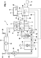
- Figure 1 shows an exemplary embodiment of a heat pump in which a refrigerant circuit is routed via power electronics comprising an inverter and, when the heat pump is in operation, heat loss can be released from the inverter to the refrigerant circuit.
- the refrigerant circuit has a Bypass fluid line through which the refrigerant can be guided past the power electronics by means of at least one valve, so that condensation of the power electronics can be prevented;
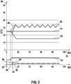
- FIG 2 shows a diagram in which when operating the in Figure 1 the heat pump shown are shown recorded temperature curves
- Figure 3 shows an example of a controllable three-way valve with which the refrigerant flow through the bypass fluid line and via the power electronics can be continuously adjusted.
- FIG. 1 shows an exemplary embodiment for a heat pump 1.
- the heat pump 1 has a compressor 2 and an electric motor 3 that is operatively connected to the compressor.
- the electric motor 3 is an electronically commutated electric motor which, in this exemplary embodiment, has a permanently magnetically designed rotor and a stator designed to generate a rotating magnetic field.
- the electric motor 3, in particular the stator coils of the stator, are connected to an inverter 4, previously also called the power output stage.
- the inverter 4 has, for example, semiconductor switch half bridges, the semiconductor switch being, for example, a field effect transistor or an insulated gate bipolar transistor.
- the inverter 4 is connected to a heat sink 5 in a thermally conductive manner.
- the cooling body 5 has at least one or more fluid channels and is designed to dissipate heat losses generated by the inverter 4 to a refrigerant flowing in the at least one fluid channel.
- the cooling body 5 is integrated into a cooling circuit of the heat pump 1 and thus forms the aforementioned section of the cooling circuit.
- the control unit 6 is connected on the input side to an ambient temperature sensor 7.
- the ambient temperature sensor 7 is designed to detect a temperature of an ambient air in the area of the inverter 4.
- the heat pump 1 also has a temperature sensor 8 which is designed and arranged to detect a temperature of the inverter 4 or, in addition, of the control unit 6.
- the control unit 6 can, for example, be part of the electronics of the heat pump 1. Both the control unit 6 and the power output stage 4 are electronic components of the heat pump 1, which should be protected from the precipitation of moisture, previously also called condensation.
- the control unit 6 is connected to a display 10 via a connecting line 32.
- the display 10 is designed as a touch screen and for this purpose has a touch-sensitive surface 11 which is connected on the output side to the control unit 6 via a connecting line 31.
- the touch-sensitive surface 11 is designed to generate a user interaction signal as a function of touching - for example by a user hand 47 - which represents a point of contact of the touch-sensitive surface 11 and to send this on the output side via the connecting line 31 to the control unit 6.
- the display 10 is designed, for example, as an LCD display, an LED display or a TFT display.
- the heat pump 1 also has a condenser 12, which in this exemplary embodiment is designed as a heat exchanger for transporting heat 34 generated and pumped by the heat pump 1 to a heating circuit.
- the condenser 12 has an input 19 for the heating circuit and an output 20 for the heating circuit.
- the condenser 12 is connected on the inlet side to the compressor 2 via a fluid line 21.
- the condenser 12 is connected on the output side via a fluid line 22 to an expansion valve 18 which is designed to be controllable in this exemplary embodiment.
- the expansion valve 18 is connected on the output side to an evaporator 13 via a fluid line 23.
- the evaporator 13 has a fan and is designed to absorb heat from an air stream 14 and to give it off to a refrigerant received by the fluid line 23.
- the evaporator 13 is connected to a branch element 25 via a fluid line 24.
- the branch element 25 divides the refrigerant flow coming from the fluid line 24 to a bypass 15 and to a controllable valve 16, which is connected to the cooling body 5 on the output side via a fluid line 27.
- the cooling body 5 is connected to the compressor 2 via a branch element 26.
- the bypass 15 is connected to the branch element 26 and thus also to the compressor 2 in the flow direction.
- the bypass 15 is designed to guide a refrigerant flow coming from the evaporator 13 past the cooling element 5 and to supply it to the compressor 2 - bypassing the cooling element 5.
- the control unit 6 is connected to the controllable valve 16 via a connecting line 30 and is designed to generate a control signal as a function of a temperature signal generated by the temperature sensor 8 and / or the ambient temperature sensor 7 and to send this to the valve 16 via the connecting line 30 . Additionally or independently of the temperature signals of the temperature sensors 7 and 8, the control unit 6 can generate the control signal for actuating the valve 16 as a function of the humidity signal generated by the humidity sensor 9.
- the humidity sensor 9 is connected to the control unit 6 via a connecting line 33.
- the control unit 6 can receive the user interaction signal via the connecting line 31 and, depending on the user interaction signal, control the inverter 4 via a connecting line 48 to energize the electric motor 3.
- the inverter 4 can then power the electric motor 3, in particular the stator of the electric motor 3, via an electrical connection 28 to generate a rotating magnetic field.
- the inverter 4 generates heat loss.
- the compressor 2 can then - driven by the electric motor 3 - generate a refrigerant flow, which via the fluid line 21, further via the condenser 12, the fluid line 22, the expansion valve 18, the fluid line 23 and the evaporator 13, further via the fluid line 24 and the valve 16, and flows via the fluid line 27 to the heat sink 5.
- the refrigerant can finally flow back from the heat sink 5 via the branch element 26 to the compressor 2.
- the control unit 6 is designed as a function of the user interaction signal to send a control signal for opening the valve 16 to the valve 16 via the connecting line 30.
- the refrigerant then flows through the opened valve 16 via the heat sink 5 to the compressor 2.
- the control unit 6 is designed to generate a difference signal as a function of the ambient temperature sensor 7 and as a function of the temperature signal generated by the temperature sensor 8, which represents a temperature difference of the temperature signals and as a function of the difference signal to generate the control signal for closing the valve 16 and on the output side via output the connecting line 30.
- the control unit 6 can have a discriminator 49 which is designed to generate the difference signal.
- the refrigerant then flows from the evaporator 13 via the branch element 25 to the bypass fluid line 15, so that the refrigerant circuit to the compressor 2 is closed via the branch element 26.
- the bypass fluid line 15 has a passage valve 17 which is designed to open at a predetermined refrigerant pressure received from the evaporator 13 and thus to release the bypass 15 for the flow of refrigerant.
- a further controllable valve 55 such as the valve 16 is arranged, which is connected to the control unit 6.
- the further valve 55 is shown in dashed lines.
- the control unit 6 can then, depending on the ambient temperature signal and the temperature signal or the humidity signal, when the temperature drops below a predetermined temperature difference between the ambient temperature and the temperature of the inverter 4, which is the predetermined temperature difference greater than the ambient temperature, a control signal for opening of the valve instead of the passage valve 17 and generate a control signal for closing the valve 16 to the heat sink 5.
- the valves 16 and 55 can each be designed to open partially or completely as a function of the control signal, so that a flow through the valve can be regulated by means of the control signal generated by the control unit 6.
- the bypass fluid line 15 does not have a pressure-dependent switching valve such as the valve 17 or the controllable valve arranged instead of the valve 17, such as the valve 16.
- the valve 16 on the branch element is open, the refrigerant flow is then divided into a portion which flows through the valve 16 via the heat sink 5 to the branch element 26 and which flows via the branch element 25 via the bypass 15 to the branch element 26 and there with that from the heat sink 5 Coming refrigerant flow combined and reaches the compressor 2.
- the branch elements 25 and 26 are each formed, for example, by a T-piece or Y-piece designed to guide fluid.
- the control unit 6 can generate a control signal to at least partially or completely open the valve 16, so that the inverter 4 can dissipate heat loss to the refrigerant via the heat sink 5.
- the efficiency of the heat pump 1 can advantageously be increased insofar as the heat loss generated by the inverter 4 cannot be given off to the environment, but rather as part of the heat 34 pumped by the heat pump 1 to the heating circuit.
- the control unit 6 is connected via a connecting line 29 to the expansion valve 18, which is designed to be controllable in this exemplary embodiment, and can regulate the output of the heat pump 1, in particular the heat output of the pumped heat 34, via the controllably designed expansion valve 18, and a corresponding control signal - for example, depending on a Generate user interaction signal received from display 10 and send it to expansion valve 18.
- Figure 2 shows a diagram which has a time axis 38 and an amplitude axis 39.
- the amplitude axis 39 represents a temperature in degrees Celsius for a curve 40, a curve 41 and a curve 42.
- the curve 40 represents a temperature of the inverter 4, for example represented by that by the temperature sensor 8 in FIG Figure 1 generated temperature signal.
- the curve 41 represents an ambient temperature signal generated by the ambient temperature sensor 7 in FIG Figure 1 .
- the temperature 42 represents a temperature of the refrigerant.
- a curve 43 which shows an on or off state of the in Figure 1 represented electric motor 3 and thus also of the compressor 2.
- a curve 44 is also shown, which shows a refrigerant flow through the bypass fluid line 15 in FIG Figure 1 represents.
- a curve 45 represents a refrigerant flow through the fluid line 27, controlled by the valve 16.
- FIG Figure 2 The refrigerant flow through the bypass fluid line 15, represented by the curve 44, is shown in FIG Figure 2
- the example shown is generated by a controllably designed valve which, instead of the passage valve 17 in FIG Figure 1 is arranged in the bypass fluid line 15.
- the control unit 6 controls the inverter 4 via the connecting line 48, for example by means of control pulses for generating a rotating magnetic field in the electric motor 3. It can be seen that the temperature of the refrigerant, represented by curve 42, is falling. If the temperature of the inverter, represented by curve 40, after time 46 is a predetermined temperature difference lower than at time 46, at time 47 the control signal for opening valve 55 instead of valve 17 in Figure 1 and the control signal for closing the valve 16 is generated.
- valve 16 is controlled to close at time 46, so that a temperature of the inverter 4 does not fall below the Ambient temperature can drop. This is shown by the dashed curve 40 '.
- the control unit 6 then regulates the temperature of the inverter in the following time curve such that the temperature of the inverter is greater than an ambient temperature, detected by the ambient temperature sensor 7 in FIG Figure 1 .
- Figure 3 shows an embodiment for a three-way valve, which instead of the in Figure 1 shown branch element 25 can be arranged.
- the three-way valve 36 has an inlet 51, an outlet 52 and an outlet 53.
- the entrance 51 is with the in Figure 1 fluid line 24 shown, the outlet 52 being connected to the bypass 15.
- the bypass 15 is connected to the branch element 26, where a refrigerant flow received from the cooling element 5 is merged with a refrigerant flow received from the bypass fluid line 15 and conducted to the compressor 2.
- the three-way valve 36 has a - for example depending on one of the in Figure 1 control signal generated control unit 6 - controllably formed adjusting element 54 on.
- the actuating element 54 is rotatably mounted in this exemplary embodiment and has a tapering fluid channel 37, which is designed to guide refrigerant received from the inlet 51 to the outlet 52 and / or to the outlet 53 as a function of a rotary position of the rotary element.
- the adjusting element 54 takes in the in Figure 3 position shown a middle position, so that the refrigerant flow to the outlets 52 and 53 is divided in equal parts.
- a pivot position 37 ′ is also shown, in which the inlet 51 is only connected to the outlet 52, so that the refrigerant flow can only be guided past the heat sink 5 via the bypass 15.
- the three-way valve 36 in particular the actuating element 54, is connected to a servomotor 50 which is designed to set an angular position of the actuating element 54 to change depending on a control signal received on the input side and to determine it in a changed position.
- the control signal can, for example, from the in Figure 1 control unit 6 shown are generated depending on the temperature signal and / or humidity signal.
Landscapes
- Engineering & Computer Science (AREA)
- Physics & Mathematics (AREA)
- Thermal Sciences (AREA)
- Microelectronics & Electronic Packaging (AREA)
- Mechanical Engineering (AREA)
- General Engineering & Computer Science (AREA)
- Chemical & Material Sciences (AREA)
- Combustion & Propulsion (AREA)
- Control Of Positive-Displacement Pumps (AREA)
- Cooling Or The Like Of Electrical Apparatus (AREA)
- Compressor (AREA)
Description
- Die Erfindung betrifft eine Wärmepumpe. Die Wärmepumpe weist einen Verdichter und einen elektronisch kommutierten Elektromotor zum Antrieb des Verdichters auf, welcher mit dem Verdichter verbunden ist. Die Wärmepumpe weist auch eine mit dem Elektromotor verbundene Leistungsendstufe, insbesondere Inverter auf, wobei die Leistungsendstufe ausgebildet ist, den Elektromotor - insbesondere zum Erzeugen eines magnetischen Drehfeldes - zu bestromen. Die Leistungsendstufe ist mit einem Abschnitt eines Kältemittelkreislaufs der Wärmepumpe wärmeleitend verbunden, sodass von der Leistungsendstufe erzeugte Verlustwärme an den Kältemittelkreislauf abgegeben werden kann.
- In der
US 2003/041607 A1 ist eine Klimaanlage beschrieben, die einen Klimakompressor, einen Elektronmotor und einen Kältemittelkreislauf umfasst, und insbesondere für Kraftfahrzeuge geeignet ist. Zur Kühlung der Steuereinrichtung des Elektromotors ist diese über verschiedene, im Kältemittelkreislauf angeordnete Ventile (Expansionsorgane) an den Kältemittelkreislauf angebunden, wobei eines der Ventile abhängig von der Temperatur der Steuereinrichtung gesteuert wird. - Bei Wärmepumpen, deren Leistungselektronik umfassend eine Leistungsendstufe von dem Kältemittelkreislauf der Wärmepumpe gekühlt wird, kann es beim Anlaufen des Verdichters, oder beim Betrieb mit durch die Leistungselektronik erzeugte geringe Verlustleistung vorkommen, dass die Temperatur der Leistungselektronik unter eine Umgebungstemperatur fällt, und die Leistungselektronik durch aus der Umgebung kondensierende Luftfeuchtigkeit betaut werden kann. Diese Betauung kann zu einem Ausfall der Leistungselektronik führen.
- Eine Wärmepumpe gemäß der Erfindung ist in Anspruch 1 definiert. Erfindungsgemäß weist die Wärmepumpe wenigstens einen Temperatursensor und optional außerdem wenigstens einen Feuchtigkeitssensor auf. Der Temperatursensor ist angeordnet, eine Temperatur der Leistungsendstufe zu erfassen und ein die Temperatur repräsentierendes Temperatursignal zu erzeugen. Der Feuchtigkeitssensor ist ausgebildet, eine Luftfeuchtigkeit im Bereich der Leistungsendstufe zu erfassen und ein die Luftfeuchtigkeit repräsentierendes Feuchtigkeitssignal zu erzeugen. Der Kältemittelkreislauf weist eine Bypass-Fluidleitung und wenigstens ein steuerbar ausgebildetes Ventil auf. Die Bypass-Fluidleitung ist ausgebildet, einen Kältemittelfluss an dem mit der Leistungsendstufe verbundenen Abschnitt vorbeizuführen. Das Ventil ist ausgebildet, in Abhängigkeit eines Steuersignals den Kältemittelfluss durch den Abschnitt freizugeben oder zu sperren. Die Wärmepumpe weist eine mit dem Temperatursensor verbundene Steuereinheit auf, welche ausgebildet ist, das Steuersignal in Abhängigkeit des Temperatursignals und/oder des Feuchtigkeitssignals zu erzeugen.
- Durch die so ausgebildete Wärmepumpe, insbesondere die Bypass-Fluidleitung und das wenigstens eine steuerbar ausgebildete Ventil kann vorteilhaft ein Unterkühlen der Leistungselektronik, insbesondere der Leistungsendstufe, und so ein Betauen der Leistungselektronik verhindert werden. Wenn beispielsweise die Temperatur der Leistungselektronik, erfasst durch den Temperatursensor, einen vorbestimmten Temperaturwert unterschreitet, so kann die Steuereinheit das Steuersignal erzeugen und so das Ventil zum Sperren des Abschnitts des Kältekreislaufs, insbesondere einer Fluidleitung des Kältekreislaufs, welcher wärmeleitend mit der Leistungselektronik wirkverbunden ist, ansteuern.
- Bevorzugt ist der Abschnitt durch einen Kühlkörper, insbesondere einen Aluminiumblock gebildet. Der Kühlkörper weist wenigstens einen Fluidkanal zum Führen von Kältemittel auf, und ist ausgebildet, mit der Leistungsendstufe wärmeleitend, bevorzugt mittels einer Wärmeleitpaste, verbunden zu werden.
- Bevorzugt ist das Ventil ein Magnetventil, welches einen elektromagnetisch bewegbar ausgebildeten Anker aufweist, welcher ausgebildet ist, den Kältemittelkreislauf bevorzugt in Abhängigkeit des Steuersignals zu unterbrechen und/oder freizugeben. Mittels des Magnetventils kann so vorteilhaft das durch den Abschnitt des Kältekreislaufs, welcher ausgebildet ist, die Leistungsendstufe zu kühlen, fließende Kühlfluid mittels eines Steuersignals steuerbar im Fluidkreislauf gelenkt werden.
- In einer bevorzugten Ausführungsform ist das Ventil ein Drei-Wege-Ventil, welches ausgebildet ist, den Kältemittelfluss durch den Abschnitt und/oder durch die Bypass-Fluidleitung zu leiten. Mittels des Drei-Wege-Ventils kann der Kältemittelfluss vorteilhaft von dem Abschnitt auf die Bypass-Fluidleitung umgelenkt werden. Bevorzugt ist das Drei-Wege-Ventil ein Schiebeventil, welches einen Ventileingang und einen mit dem Abschnitt verbundenen Ventilausgang und einen weiteren mit der Bypass-Fluidleitung verbundenen Ventilausgang aufweist. Das Schiebeventil weist ein bevorzugt in Abhängigkeit des Steuersignals betätigbar ausgebildetes Stellelement oder Schiebeelement auf, welches wenigstens einen Durchbruch aufweist, welcher ausgebildet ist, den Fluidstrom von dem Eingang zu der Bypass-Fluidleitung oder dem Abschnitt zu leiten, und das Stellelement dazu drehbar oder das Schiebelement dazu axial verschiebbar gelagert ist. So kann beispielsweise entlang eines Dreh- oder Schiebeweges des Schiebers der in dem Schieber beziehungsweise Stellelement angeordnete Durchbruch von einer Öffnung für den Abschnitt weggeschwenkt oder weggeschoben werden und dabei vor eine Öffnung für die Bypass-Fluidleitung - innerhalb des Drei-Wege-Ventils - bewegt werden. Bevorzugt kann so der Fluidstrom stufenlos von dem Ausgang für den Abschnitt, auf den Ausgang für die Bypass-Fluidleitung umgestellt werden. Vorteilhaft kann so bei einer mittleren Stellung des Schiebers sowohl ein Kältemittelfluss durch den Abschnitt fließen als auch durch die Bypass-Fluidleitung, bevorzugt zu gleichen Teilen in der zuvor genannten mittleren Stellung. Bevorzugt ist dabei eine Summe der Durchflüsse durch den Abschnitt und die Bypass-Fluidleitung konstant und so unabhängig von einer Stellung des Schiebers beziehungsweise Stellelements.
- In einer bevorzugten Ausführungsform weist die Wärmepumpe zwei steuerbar ausgebildete Ventile auf, wobei ein Ventil ausgebildet und angeordnet ist, den Kältemittelfluss durch den Abschnitt zu öffnen oder zu schließen und ein weiteres Bypass-Ventil ausgebildet und angeordnet ist, den Kältemittelfluss durch die Bypass-Fluidleitung zu öffnen oder zu schließen. Die Steuereinheit ist mit dem Bypass-Ventil verbunden und ausgebildet, in Abhängigkeit des Temperatursignals und/oder des Feuchtigkeitssignals das Bypass-Ventil zum Öffnen anzusteuern und das Ventil zum Sperren des Abschnitts anzusteuern. So kann der Kältemittelfluss von dem die Leistungsendstufe kühlenden Abschnitt auf den Bypass umgeschaltet werden.
- In einer bevorzugten Ausführungsform weist die Wärmepumpe ein Durchlassventil auf, welches ausgebildet und angeordnet ist, den Kältemittelfluss durch die Bypass-Fluidleitung in Abhängigkeit eines Fluiddruckes des Kältemittels freizugeben oder zu sperren. Bevorzugt ist das Durchlassventil in der Bypass-Fluidleitung angeordnet. So kann vorteilhaft das zuvor erwähnte steuerbar ausgebildete Ventil in der Bypass-Fluidleitung durch das passive, druckabhängig schaltende Durchlassventil ersetzt werden. Wenn beispielsweise die Steuereinheit das Steuersignal zum Sperren des Abschnitts erzeugt und an das steuerbar ausgebildete Ventil zum Sperren des Kältemittelflusses durch den die Leistungsendstufe kühlenden Abschnitt sendet, so steigt der Kältemitteldruck in dem Kältemittelkreislauf vor dem Abschnitt an, sodass sich das Durchlassventil in Abhängigkeit des Druckanstiegs öffnen kann und so der Kältemittelfluss der Wärmepumpe über den Bypass weiter aufrecht erhalten werden kann.
- Erfindungsgemäß weist die Wärmepumpe einen mit der Steuereinheit verbundenen Umgebungstemperatursensor auf. Der Umgebungstemperatursensor ist ausgebildet, eine Umgebungstemperatur zu erfassen und ein die Umgebungstemperatur repräsentierendes Umgebungstemperatursignal zu erzeugen. Die Steuereinheit ist ausgebildet, das Steuersignal für das wenigstens eine Ventil derart zu erzeugen, dass die Temperatur der Leistungsendstufe größer als die Umgebungstemperatur ist. Erfindungsgemäß ist die Steuereinheit ausgebildet, die Temperatur der Leistungsendstufe um ein vorbestimmtes Temperaturintervall größer als die Umgebungstemperatur zu regeln. So kann vorteilhaft mittels der zuvor erwähnten erfassten Temperaturen das Betauen der Leistungselektronik zuverlässig verhindert werden.
- In einer bevorzugten Ausführungsform ist die Steuereinheit ausgebildet, das Steuersignal derart zu erzeugen, dass der Kältemittelfluss periodisch alternierend durch den Abschnitt und durch die Bypass-Fluidleitung fließt. Dadurch können die Ventile jeweils vorteilhaft als - insbesondere aufwandsgünstig bereitzustellendes - Magnetventil ausgebildet sein, welches ausgebildet ist, in Abhängigkeit des Steuersignals einen Durchfluss vollständig freigeben oder zu sperren.
- In einer anderen Ausführungsform repräsentiert das Steuersignal einen Öffnungsgrad des Ventils zwischen einer vollen Öffnung und einer gesperrten Ventilstellung, so dass mittels der Steuereinheit der Durchfluss durch beide Ventile mittels einer Regelung teilweise freigegeben sein kann.
- In einer anderen Ausführungsform kann der Kältemittelfluss - mittels des zuvor erwähnten Drei-Wege-Ventils in der Ausführungsform des Schiebers - gleichzeitig durch den Abschnitt und durch die Bypass-Fluidleitung fließen. Mittels der so ausgebildeten Steuereinheit kann anstelle der Ausführungsform mit zwei Ventilen vorteilhaft mit nur einem Ventil ein Kühlmittelfluss sowohl durch den Abschnitt als auch die Bypass-Fluidleitung erzeugt werden.
- In einer bevorzugten Ausführungsform ist die Steuereinheit ausgebildet, das Steuersignal derart zu erzeugen, dass der Kältemittelfluss jeweils für ein vorbestimmtes Zeitintervall alternierend durch den Abschnitt oder durch die Bypass-Fluidleitung fließt. Bevorzugt wird das Zeitintervall von einem Pulsweitenmodulator erzeugt. So kann die Wärmepumpe vorteilhaft in der Ausführungsform mit wenigstens einem Ventil oder zusätzlich dem Durchlassventil oder in der Ausführungsform mit zwei Ventilen, nämlich einem Ventil für den Abschnitt und einem weiteren Ventil für die Bypass-Fluidleitung, die Kühlleistung auf dem Abschnitt, welcher Wärme von der Leistungsendstufe abführen kann, mittels pulsweitenmodulierter Signale gesteuert werden.
- Bevorzugt weist die Wärmepumpe ein Abzweigelement auf, welches eingangsseitig mit einem Verdampfer der Wärmepumpe verbunden ist und mit einem ersten Ausgang mit der Bypass-Fluidleitung und einem zweiten Ausgang mit dem Abschnitt, insbesondere Kühlkörper verbunden ist. Das Abzweigelement ist ausgebildet, den eingangsseitig empfangenen Kältemittelstrom auf den ersten und den zweiten Ausgang aufzuteilen und dort auszugeben.
- Die Erfindung betrifft auch ein Verfahren zum Verhindern einer Betauung einer Leistungsendstufe einer Wärmepumpe, wobei die Leistungsendstufe über einen Kältemittelkreislauf der Wärmepumpe gekühlt wird. Ein solches Verfahren gemäß der Erfindung ist in Anspruch 8 definiert.
- Bevorzugt wird bei dem Verfahren eine Temperatur der Leistungsendstufe erfasst und ein die Temperatur repräsentierendes Temperatursignal erzeugt. Weiter bevorzugt wird in Abhängigkeit des Temperatursignals ein Kältemittelfluss an der Leistungsendstufe unterbrochen oder reduziert und das Kältemittel zum Weiterbetrieb der Wärmepumpe an der Leistungsendstufe - bevorzugt durch einen Bypass - wenigstens teilweise oder vollständig vorbeigeführt.
- Erfindungsgemäß wird bei dem Verfahren eine Umgebungstemperatur erfasst und ein die Umgebungstemperatur repräsentierendes Umgebungstemperatursignal erzeugt. Bevorzugt wird während des Betriebs der Wärmepumpe die Temperatur der Leistungsendstufe in Abhängigkeit des Umgebungstemperatursignals derart geregelt, dass die Temperatur der Leistungsendstufe größer ist als die Umgebungstemperatur.
- Die Erfindung wird nun im Folgenden anhand von weiteren Ausführungsbeispielen beschrieben. Weitere vorteilhafte Ausführungsvarianten ergeben sich aus den in den abhängigen Ansprüchen und den Figuren beschriebenen Merkmalen.
-
Figur 1 zeigt ein Ausführungsbeispiel für eine Wärmepumpe, bei der ein Kältemittelkreislauf über eine Leistungselektronik umfassend einen Inverter geführt ist und beim Betrieb der Wärmepumpe Verlustwärme von dem Inverter an den Kältemittelkreislauf abgegeben werden kann. Der Kältemittelkreislauf weist eine Bypass-Fluidleitung auf, durch welche das Kältemittel mittels wenigstens eines Ventils an der Leistungselektronik vorbeigeführt werden kann, so dass eine Betauung der Leistungselektronik verhindert werden kann; -
Figur 2 zeigt ein Diagramm in dem beim Betrieb der inFigur 1 dargestellten Wärmepumpe aufgezeichnete Temperaturkurven dargestellt sind; -
Figur 3 zeigt ein Beispiel für ein steuerbar ausgebildetes Drei-Wege-Ventil, mit dem der Kältemittelfluss durch die Bypass-Fluidleitung und über die Leistungselektronik stufenlos eingestellt werden kann. -
Figur 1 zeigt ein Ausführungsbeispiel für eine Wärmepumpe 1. Die Wärmepumpe 1 weist einen Verdichter 2 und einen mit dem Verdichter wirkverbundenen Elektromotor 3 auf. Der Elektromotor 3 ist eine elektronisch kommutierter Elektromotor, welcher in diesem Ausführungsbeispiel einen permanentmagnetisch ausgebildeten Rotor und einen zum Erzeugen eines magnetischen Drehfeldes ausgebildeten Stator aufweist. Der Elektromotor 3, insbesondere Statorspulen des Stators, sind mit einem Inverter 4, zuvor auch Leistungsendstufe genannt, verbunden. Der Inverter 4 weist beispielsweise Halbleiterschalter-Halbbrücken auf, wobei der Halbleiterschalter beispielsweise ein Feldeffekttransistor oder ein Insulated-Gate-Bipolar-Transistor ist. - Der Inverter 4 ist mit einem Kühlkörper 5 wärmeleitend verbunden. Der Kühlkörper 5 weist in diesem Ausführungsbeispiel wenigstens einen oder mehrere Fluidkanäle auf und ist ausgebildet, von dem Inverter 4 erzeugte Verlustwärme an ein in dem wenigstens einen Fluidkanal fließenden Kältemittel abzuführen. Der Kühlkörper 5 ist in einen Kältekreislauf der Wärmepumpe 1 eingebunden und bildet so den zuvor erwähnten Abschnitt des Kältekreislaufs.
- Die Wärmepumpe 1 weist auch eine Steuereinheit 6 auf, welche beispielsweise durch einen Mikroprozessor oder einen Mikrocontroller oder ein FPGA (FPGA = Field-Programmable-Gate-Array) gebildet ist. Die Steuereinheit 6 ist eingangsseitig mit einem Umgebungstemperatursensor 7 verbunden. Der Umgebungstemperatursensor 7 ist ausgebildet, eine Temperatur einer Umgebungsluft im Bereich des Inverters 4 zu erfassen.
- Die Wärmepumpe 1 weist auch einen Temperatursensor 8 auf, welcher ausgebildet und angeordnet ist, eine Temperatur des Inverters 4 oder zusätzlich der Steuereinheit 6 zu erfassen. Die Steuereinheit 6 kann beispielsweise Bestandteil einer Elektronik der Wärmepumpe 1 sein. Sowohl die Steuereinheit 6 als auch die Leistungsendstufe 4 sind elektronische Komponenten der Wärmepumpe 1, welche vor einem Feuchtigkeitsniederschlag, zuvor auch Betauung genannt, geschützt werden soll.
- Die Steuereinheit 6 ist ausgangsseitig über eine Verbindungsleitung 32 mit einem Display 10 verbunden. Das Display 10 ist in diesem Ausführungsbeispiel als Touch-Screen ausgebildet und weist dazu eine berührungsempfindliche Oberfläche 11 auf, welche ausgangsseitig über eine Verbindungsleitung 31 mit der Steuereinheit 6 verbunden ist. Die berührungsempfindliche Oberfläche 11 ist ausgebildet, in Abhängigkeit eines Berührens - beispielsweise durch eine Benutzerhand 47 - ein Benutzerinteraktionssignal zu erzeugen, welches einen Berührungsort der berührungsempfindlichen Oberfläche 11 repräsentiert und dieses ausgangsseitig über die Verbindungsleitung 31 an die Steuereinheit 6 zu senden.
- Das Display 10 ist beispielsweise als LCD-Display, als LED-Display oder als TFT-Display ausgebildet.
- Die Wärmepumpe 1 weist auch einen Verflüssiger 12 auf, welcher in diesem Ausführungsbeispiel einen Wärmetauscher zum Transportieren von der Wärmepumpe 1 erzeugter und gepumpter Wärme 34 zu einem Heizungskreislauf hin ausgebildet ist. Der Verflüssiger 12 weist dazu einen Eingang 19 für den Heizungskreislauf und einen Ausgang 20 für den Heizungskreislauf auf. Der Verflüssiger 12 ist eingangsseitig über eine Fluidleitung 21 mit dem Verdichter 2 verbunden. Der Verflüssiger 12 ist ausgangsseitig über eine Fluidleitung 22 mit einem in diesem Ausführungsbeispiel steuerbar ausgebildeten Expansionsventil 18 verbunden. Das Expansionsventil 18 ist ausgangsseitig über eine Fluidleitung 23 mit einem Verdampfer 13 verbunden. Der Verdampfer 13 weist in diesem Ausführungsbeispiel einen Ventilator auf und ist ausgebildet, Wärme aus einem Luftstrom 14 aufzunehmen und an ein von der Fluidleitung 23 empfangenes Kältemittel abzugeben. Der Verdampfer 13 ist ausgangsseitig über eine Fluidleitung 24 mit einem Abzweigelement 25 verbunden. Das Abzweigelement 25 teilt den Kältemittelfluss von der Fluidleitung 24 kommend zu einem Bypass 15 hin und zu einem steuerbar ausgebildeten Ventil 16 hin, welches über eine Fluidleitung 27 ausgangsseitig mit dem Kühlkörper 5 verbunden ist. Der Kühlkörper 5 ist ausgangsseitig über ein Abzweigelement 26 mit dem Verdichter 2 verbunden.
- Der Bypass 15 ist mit dem Abzweigelement 26 und so auch in Flussrichtung mit dem Verdichter 2 verbunden. Der Bypass 15 ist ausgebildet, einen Kältemittelfluss von dem Verdampfer 13 kommend an dem Kühlkörper 5 vorbeizuführen und dem Verdichter 2 - unter Umgehung des Kühlkörpers 5 - zuzuführen.
- Die Steuereinheit 6 ist über eine Verbindungsleitung 30 mit dem steuerbar ausgebildeten Ventil 16 verbunden und ist ausgebildet, in Abhängigkeit eines von dem Temperatursensor 8 und/oder dem Umgebungstemperatursensor 7 erzeugten Temperatursignals ein Steuersignal zu erzeugen und dieses über die Verbindungsleitung 30 an das Ventil 16 zu senden. Zusätzlich oder unabhängig von den Temperatursignalen der Temperatursensoren 7 und 8 kann die Steuereinheit 6 das Steuersignal zum Betätigen des Ventils 16 in Abhängigkeit des von dem Feuchtigkeitssensor 9 erzeugten Feuchtigkeitssignal erzeugen. Der Feuchtigkeitssensor 9 ist über eine Verbindungsleitung 33 mit der Steuereinheit 6 verbunden.
- Die Funktionsweise der Wärmepumpe 1 wird nun im Folgenden beschrieben:
Wenn beispielsweise mittels der Benutzerhand 47 von der berührungsempfindlichen Oberfläche 11 des Displays 10 ein Benutzerinteraktionssignal erzeugt wird, kann die Steuereinheit 6 das Benutzerinteraktionssignal über die Verbindungsleitung 31 empfangen und in Abhängigkeit des Benutzerinteraktionssignals den Inverter 4 über eine Verbindungsleitung 48 zum Bestromen des Elektromotors 3 ansteuern. Der Inverter 4 kann dann über eine elektrische Verbindung 28 den Elektromotor 3, insbesondere den Stator des Elektromotors 3, zum Erzeugen eines magnetischen Drehfeldes bestromen. Dabei erzeugt der Inverter 4 Verlustwärme. Der Verdichter 2 kann dann - angetrieben durch den Elektromotor 3 - einen Kältemittelfluss erzeugen, welcher über die Fluidleitung 21, weiter über den Verflüssiger 12, die Fluidleitung 22, das Expansionsventil 18, die Fluidleitung 23 und den Verdampfer 13, weiter über die Fluidleitung 24 und das Ventil 16, und über die Fluidleitung 27 zum Kühlkörper 5 fließt. Das Kältemittel kann vom Kühlkörper 5 schließlich über das Abzweigelement 26 zum Verdichter 2 zurückfließen. Die Steuereinheit 6 ist ausgebildet, in Abhängigkeit des Benutzerinteraktionssignals ein Steuersignal zum Öffnen des Ventils 16 über die Verbindungsleitung 30 an das Ventil 16 zu senden. Das Kältemittel fließt dann durch das geöffnete Ventil 16 über den Kühlkörper 5 zum Verdichter 2. - Nach einem Anlaufen des Verdichters 2 sinkt dabei eine Temperatur des Kühlmittels am Verdampfer 13 stark ab, sodass der mit dem Kühlkörper 5 wärmeleitend verbundene Inverter 4 beispielsweise auf eine Temperatur kleiner als eine Umgebungstemperatur abgekühlt werden kann. Die Steuereinheit 6 ist ausgebildet, in Abhängigkeit des Umgebungstemperatursensors 7 erzeugten Umgebungstemperatursignals und in Abhängigkeit des vom Temperatursensor 8 erzeugten Temperatursignals ein Differenzsignal zu erzeugen, welches eine Temperaturdifferenz der Temperatursignale repräsentiert und in Abhängigkeit des Differenzsignals das Steuersignal zum Schließen des Ventils 16 zu erzeugen und ausgangsseitig über die Verbindungsleitung 30 auszugeben. Die Steuereinheit 6 kann dazu einen Diskriminator 49 aufweisen, welcher ausgebildet ist, das Differenzsignal zu erzeugen.
- Das Kältemittel fließt dann von dem Verdampfer 13 über das Abzweigelement 25 zur Bypass-Fluidleitung 15, sodass der Kältemittelkreislauf zum Verdichter 2 hin über das Abzweigelement 26 geschlossen ist.
- Die Bypass-Fluidleitung 15 weist in diesem Ausführungsbeispiel ein Durchlassventil 17 auf, welches ausgebildet ist, bei einem vorbestimmten Kältemitteldruck, empfangen vom Verdampfer 13, zu öffnen und so den Bypass 15 für den Kältemittelfluss freizugeben.
- In einer anderen Ausführungsform ist anstelle des Durchlassventils 17 ein weiteres steuerbar ausgebildetes Ventil 55 wie das Ventil 16 angeordnet, welches mit der Steuereinheit 6 verbunden ist. Das weitere Ventil 55 ist gestrichelt dargestellt. Die Steuereinheit 6 kann dann in Abhängigkeit des Umgebungstemperatursignals und des Temperatursignals oder des Feuchtigkeitssignals bei Unterschreiten einer vorbestimmten Temperaturdifferenz zwischen der Umgebungstemperatur und der Temperatur des Inverters 4, welche um die vorbestimmte Temperaturdifferenz größer ist als die Umgebungstemperatur, ein Steuersignal zum Öffnen des Ventils anstelle des Durchlassventils 17 und ein Steuersignal zum Schließen des Ventils 16 zum Kühlkörper 5 hin erzeugen. Die Ventile 16 und 55 können jeweils ausgebildet sein, in Abhängigkeit des Steuersignals teilweise oder vollständig zu öffnen, so dass mittels des Steuersignals, erzeugt durch die Steuereinheit 6, ein Durchfluss durch das Ventil geregelt werden kann.
- In einer anderen Ausführungsform weist die Bypass-Fluidleitung 15 kein druckabhängig schaltendes Durchlassventil wie das Durchlassventil 17 oder das anstelle des Durchlassventils 17 angeordneten steuerbar ausgebildeten Ventils wie das Ventil 16 auf. Der Kältemittelfluss teilt sich dann bei geöffnetem Ventil 16 am Abzweigelement in einen Anteil, welcher durch das Ventil 16 über den Kühlkörper 5 zum Abzweigelement 26 hinfließt und welcher über das Abzweigelement 25 über den Bypass 15 zum Abzweigelement 26 fließt und sich dort mit dem vom Kühlkörper 5 kommenden Kältemittelfluss vereint und zum Verdichter 2 gelangt.
- Die Abzweigelemente 25 und 26 sind beispielsweise jeweils durch ein zum Fluidführen ausgebildetes T-Stück oder Y-Stück gebildet.
- Wenn die Temperatur des Inverters, erfasst durch den Temperatursensor 8, weiter ansteigt, kann die Steuereinheit 6 ein Steuersignal zum wenigstens teilweisen oder vollständigen Öffnen des Ventils 16 erzeugen, sodass der Inverter 4 über den Kühlkörper 5 Verlustwärme an das Kältemittel abgeben kann. So kann vorteilhaft ein Wirkungsgrad der Wärmepumpe 1 vergrößert werden, insoweit die vom Inverter 4 erzeugte Verlustwärme nicht an eine Umgebung, sondern als Bestandteil der von der Wärmepumpe 1 gepumpten Wärme 34 an den Heizungskreislauf abgegeben werden kann.
- Die Steuereinheit 6 ist über eine Verbindungsleitung 29 mit dem in diesem Ausführungsbeispiel steuerbar ausgebildeten Expansionsventil 18 verbunden und kann eine Leistung der Wärmepumpe 1, insbesondere die Wärmeleistung der gepumpten Wärme 34 über das steuerbar ausgebildete Expansionsventil 18 regeln und dazu ein entsprechendes Steuersignal - beispielsweise in Abhängigkeit eines vom Display 10 empfangenen Benutzerinteraktionssignal erzeugen und an das Expansionsventil 18 senden.
-
Figur 2 zeigt ein Diagramm, welches eine Zeitachse 38 und eine Amplitudenachse 39 aufweist. Die Amplitudenachse 39 repräsentiert eine Temperatur in Grad Celsius für eine Kurve 40, eine Kurve 41 und eine Kurve 42. Die Kurve 40 repräsentiert eine Temperatur des Inverters 4, beispielsweise repräsentiert durch das durch den Temperatursensor 8 inFigur 1 erzeugte Temperatursignal. Die Kurve 41 repräsentiert ein Umgebungstemperatursignal, erzeugt durch den Umgebungstemperatursensor 7 inFigur 1 . Die Temperatur 42 repräsentiert eine Temperatur des Kältemittels. - Dargestellt ist auch eine Kurve 43, welche einen Ein- beziehungsweise Ausschaltzustand des in
Figur 1 dargestellten Elektromotors 3 und so auch des Verdichters 2 repräsentiert. Dargestellt ist auch eine Kurve 44, welche einen Kältemittelfluss durch die Bypass-Fluidleitung 15 inFigur 1 repräsentiert. Eine Kurve 45 repräsentiert einen Kältemittelfluss durch die Fluidleitung 27, gesteuert durch das Ventil 16. - Der Kältemittelfluss durch die Bypass-Fluidleitung 15, repräsentiert durch die Kurve 44, wird in dem in
Figur 2 dargestellten Beispiel durch ein steuerbar ausgebildetes Ventil erzeugt, welches anstelle des Durchlassventils 17 inFigur 1 in der Bypass-Fluidleitung 15 angeordnet ist. - Zu einem Zeitpunkt 46 wird von der Steuereinheit 6 der Inverter 4 über die Verbindungsleitung 48 - beispielsweise mittels Steuerpulsen zum Erzeugen eines magnetischen Drehfelds im Elektromotor 3 - angesteuert. Sichtbar ist, dass die Temperatur des Kältemittels, repräsentiert durch die Kurve 42, absinkt. Wenn die Temperatur des Inverters, repräsentiert durch die Kurve 40, nach dem Zeitpunkt 46 um eine vorbestimmte Temperaturdifferenz kleiner ist als zum Zeitpunkt 46, so wird zu einem Zeitpunkt 47 das Steuersignal zum Öffnen des Ventils 55 anstelle des Ventils 17 in
Figur 1 und das Steuersignal zum Schließen des Ventils 16 erzeugt. - In einer anderen Ausführungsform wird das Ventil 16 zum Zeitpunkt 46 zum Schließen angesteuert, so dass eine Temperatur des Inverters 4 nicht unter die Umgebungstemperatur fallen kann. Das ist durch die gestrichtelte Kurve 40' dargestellt.
- Die Steuereinheit 6 regelt dann im folgenden Zeitverlauf die Temperatur des Inverters derart, dass die Temperatur des Inverters größer ist als eine Umgebungstemperatur, erfasst durch den Umgebungstemperatursensor 7 in
Figur 1 . -
Figur 3 zeigt ein Ausführungsbeispiel für ein Drei-Wege-Ventil, welches anstelle des inFigur 1 dargestellten Abzweigelements 25 angeordnet sein kann. - Das Drei-Wege-Ventil 36 weist einen Eingang 51, einen Ausgang 52 und einen Ausgang 53 auf.
- Der Eingang 51 ist mit der in
Figur 1 dargestellten Fluidleitung 24 verbunden, wobei der Ausgang 52 mit dem Bypass 15 verbunden ist. - Der Bypass 15 ist mit dem Abzweigelement 26 verbunden, wo ein von dem Kühlelement 5 empfangener Kältemittelfluss mit einem von der Bypass-Fluidleitung 15 empfangenen Kältemittelfluss zusammengeführt und an den Verdichter 2 geleitet wird.
- Das Drei-Wege-Ventil 36 weist ein - beispielsweise in Abhängigkeit eines von der in
Figur 1 dargestellten Steuereinheit 6 erzeugten Steuersignal - steuerbar ausgebildetes Stellelement 54 auf. Das Stellelement 54 ist in diesem Ausführungsbeispiel drehbar gelagert und weist einen sich verjüngenden Fluidkanal 37 auf, welcher ausgebildet ist, vom Eingang 51 empfangenes Kältemittel in Abhängigkeit einer Drehstellung des Drehelements zum Ausgang 52 und/oder zum Ausgang 53 zu leiten. Das Stellelement 54 nimmt in der inFigur 3 dargestellten Position eine Mittelstellung ein, sodass der Kältemittelfluss auf die Ausgänge 52 und 53 zu gleichen Teilen aufgeteilt wird. Dargestellt ist auch eine Schwenkstellung 37', in der der Eingang 51 nur mit dem Ausgang 52 verbunden ist, sodass der Kältemittelfluss nur über den Bypass 15 am Kühlkörper 5 vorbeigeleitet werden kann. Das Drei-Wege-Ventil 36, insbesondere das Stellelement 54, ist mit einem Stellmotor 50 verbunden, welcher ausgebildet ist, eine Winkelstellung des Stellelements 54 in Abhängigkeit eines eingangsseitig empfangenen Steuersignals zu ändern und in einer geänderten Position festzustellen. Das Steuersignal kann beispielsweise von der inFigur 1 gezeigten Steuereinheit 6 in Abhängigkeit des Temperatursignals und/oder Feuchtigkeitssignals erzeugt werden.
Claims (8)
- Wärmepumpe (1) mit einem Verdichter (2), und einem mit dem Verdichter (2) verbundenen elektronisch kommutierten Elektromotor zum Antrieb des Verdichters, wobei die Wärmepumpe eine mit dem Elektromotor verbundene Leistungsendstufe (4) aufweist, welche ausgebildet ist, den Elektromotor zu bestromen, und die Leistungsendstufe (7) mit einem Abschnitt (5) eines Kältemittelkreislaufs (5, 21, 22, 23, 24, 27) der Wärmepumpe (1) wärmeleitend verbunden ist, so dass von der Leistungsendstufe (4) erzeugte Verlustwärme an den Kältemittelkreislauf (5, 21, 22, 23, 24, 27) abgegeben werden kann, wobei die Wärmepumpe (1) wenigstens einen Temperatursensor (8) aufweist, wobei der Temperatursensor (8) angeordnet ist, eine Temperatur der Leistungsendstufe (4) zu erfassen und ein die Temperatur repräsentierendes Temperatursignal zu erzeugen, wobei der Kältemittelkreislauf (21, 22, 23, 24, 27) eine Bypass-Fluidleitung (15) und wenigstens ein steuerbar ausgebildetes Ventil (16, 36, 55) aufweist, wobei die Bypass-Fluidleitung (15) ausgebildet und angeordnet ist, einen Kältemittelfluß an dem Abschnitt (5) vorbeizuführen und das Ventil (16, 36, 55) ausgebildet ist, in Abhängigkeit eines Steuersignals den Kältemittelfluß durch den Abschnitt (5) freizugeben oder zu sperren, und die Wärmepumpe (1) eine mit dem Temperatursensor (8) verbundene Steuereinheit (6) aufweist, welche ausgebildet ist, das Steuersignal in Abhängigkeit des Temperatursignals zu erzeugen.
dadurch gekennzeichnet, dass
die Wärmepumpe (1) einen mit der Steuereinheit (6) verbundenen Umgebungstemperatursensor (7) aufweist, welcher ausgebildet ist eine Umgebungstemperatur zu erfassen und ein die Umgebungstemperatur repräsentierendes Umgebungstemperatursignal zu erzeugen und die Steuereinheit (6) ausgebildet ist, das Steuersignal derart zu erzeugen, dass die Temperatur der Leistungsendstufe (4) größer als die Umgebungstemperatur ist. - Wärmepumpe (1) nach Anspruch 1,
dadurch gekennzeichnet, dass
das Ventil (16, 17, 36, 55) ein Magnetventil ist, welches einen elektromagnetisch bewegbar ausgebildeten Anker aufweist, welcher ausgebildet ist, in Abhängigkeit des Steuersignals den Kältemittelkreislauf zu unterbrechen und/oder freizugeben. - Wärmepumpe (1) nach Anspruch 1 oder 2,
dadurch gekennzeichnet, dass
das Ventil ein 3-Wege-Ventil (36) ist, welches ausgebildet ist, den Kältemittelfluß durch den Abschnitt (5) und/oder die Bypass-Fluidleitung (15) zu leiten. - Wärmepumpe (1) nach Anspruch 1 oder 2,
dadurch gekennzeichnet, dass
die Wärmepumpe (1) zwei steuerbar ausgebildete Ventile (16) aufweist, wobei ein Ventil (16) ausgebildet und angeordnet ist, den Kältemittelfluß durch den Abschnitt zu öffnen oder zu schließen, und ein weiteres Ventil (55) ausgebildet und angeordnet ist, den Kältemittelfluß durch die Bypass-Fluidleitung (15) zu öffnen oder zu schließen, wobei die Steuereinheit (6) mit dem weiteren Ventil (55) verbunden und ausgebildet ist, in Abhängigkeit des Temperatursignals das weitere Ventil (55) zum Öffnen anzusteuern und das Ventil (16) zum Sperren des Abschnitts (5) anzusteuern. - Wärmepumpe (1) nach Anspruch 1 oder 2,
dadurch gekennzeichnet, dass
die Wärmepumpe (1) ein Durchlassventil (17) aufweist, welches ausgebildet und angeordnet ist, den Kältemittelfluß durch die Bypass-Fluidleitung (15) in Abhängigkeit eines Fluiddruckes des Kältemittels freizugeben oder zu sperren. - Wärmepumpe (1) nach einem der vorhergehenden Ansprüche,
dadurch gekennzeichnet, dass
die Steuereinheit (6) ausgebildet ist, das Steuersignal derart zu erzeugen, dass der Kältemittelfluß alternierend durch den Abschnitt (5) und durch die Bypass-Fluidleitung (15) fließt. - Wärmepumpe (1) nach Anspruch 6,
dadurch gekennzeichnet, dass
die Steuereinheit (6) ausgebildet ist, das Steuersignal derart zu erzeugen, dass der Kältemittelfluß jeweils für ein vorbestimmtes Zeitintervall alternierend durch den Abschnitt (5) und durch die Bypass-Fluidleitung (15) fließt. - Verfahren zum Verhindern einer Betauung einer Leistungsendstufe (4) einer Wärmepumpe (1), wobei die Leistungsendstufe (4) über einen Kältemittelkreislauf (5, 21, 22, 23, 24, 27) der Wärmepumpe (1) gekühlt wird, wobei eine Temperatur der Leistungsendstufe (4) erfasst wird, ein die Temperatur repräsentierendes Temperatursignal (40) erzeugt wird und in Abhängigkeit des Temperatursignals ein Kältemittelfluß an der Leistungsendstufe (4) unterbrochen oder reduziert wird, und das Kältemittel zum Weiterbetrieb der Wärmepumpe (1) an der Leistungsendstufe (4) wenigstens teilweise oder vollständig vorbeigeführt wird.
dadurch gekennzeichnet, dass
eine Umgebungstemperatur erfasst wird und ein die Umgebungstemperatur repräsentierendes Umgebungstemperatursignal (41) erzeugt wird und während des Betriebs der Wärmepumpe (1) die Temperatur der Leistungsendstufe (4) in Abhängigkeit des Umgebungstemperatursignals (41) derart geregelt wird, dass die Temperatur der Leistungsendstufe (4) größer ist als die Umgebungstemperatur.
Applications Claiming Priority (1)
| Application Number | Priority Date | Filing Date | Title |
|---|---|---|---|
| DE201310225450 DE102013225450B3 (de) | 2013-12-10 | 2013-12-10 | Wärmepumpe mit einem kältemittelgekühlten Inverter |
Publications (3)
| Publication Number | Publication Date |
|---|---|
| EP2884204A2 EP2884204A2 (de) | 2015-06-17 |
| EP2884204A3 EP2884204A3 (de) | 2015-06-24 |
| EP2884204B1 true EP2884204B1 (de) | 2020-10-28 |
Family
ID=51868819
Family Applications (1)
| Application Number | Title | Priority Date | Filing Date |
|---|---|---|---|
| EP14191552.0A Active EP2884204B1 (de) | 2013-12-10 | 2014-11-03 | Wärmepumpe mit einem kältemittelgekühlten Inverter |
Country Status (2)
| Country | Link |
|---|---|
| EP (1) | EP2884204B1 (de) |
| DE (1) | DE102013225450B3 (de) |
Cited By (1)
| Publication number | Priority date | Publication date | Assignee | Title |
|---|---|---|---|---|
| DE102022134177A1 (de) | 2022-12-20 | 2024-06-20 | Viessmann Climate Solutions Se | Wärmepumpe und verfahren zum betreiben der wärmepumpe |
Families Citing this family (9)
| Publication number | Priority date | Publication date | Assignee | Title |
|---|---|---|---|---|
| EP3217116A1 (de) * | 2016-03-09 | 2017-09-13 | Vaillant GmbH | Rückgewinnung von durch einen verdichterantrieb erzeugter wärme |
| EP3425307B1 (de) | 2017-07-03 | 2024-08-07 | Ningbo Geely Automobile Research & Development Co. Ltd. | Verfahren zur steuerung eines wärmepumpensystems |
| CN109640580B (zh) * | 2018-10-22 | 2020-05-12 | 无锡地铁集团有限公司 | 一种盾构隧道试验平台精密液压元件户外防护装置及方法 |
| DE202019100059U1 (de) | 2019-01-08 | 2019-02-11 | Vaillant Gmbh | Inverteranordnung |
| DE102019204492A1 (de) * | 2019-03-29 | 2020-10-01 | Siemens Mobility GmbH | Verfahren zum Betreiben einer Wärmepumpe, Wärmepumpe, Belüftungsanlage und Fahrzeug |
| DE102020115492A1 (de) | 2020-06-10 | 2021-12-16 | Ebm-Papst Mulfingen Gmbh & Co. Kg | Kraftwärmemaschine |
| DE102020132713A1 (de) | 2020-12-09 | 2022-06-09 | Vaillant Gmbh | Verfahren und Vorrichtungen zur Temperaturregelung einer Leistungselektronik an einer Klima- und/oder Heizanlage |
| DE102021106599A1 (de) * | 2021-03-18 | 2022-09-22 | Man Truck & Bus Se | Flüssigkeitsgekühlter Wechselrichter zur Ansteuerung eines elektrischen Antriebsmotors eines Fahrzeugs |
| DE102024207331A1 (de) | 2024-08-02 | 2026-02-05 | Robert Bosch Gesellschaft mit beschränkter Haftung | Verfahren zum Temperieren eines Steuergeräts |
Family Cites Families (5)
| Publication number | Priority date | Publication date | Assignee | Title |
|---|---|---|---|---|
| US6032472A (en) * | 1995-12-06 | 2000-03-07 | Carrier Corporation | Motor cooling in a refrigeration system |
| US6116040A (en) * | 1999-03-15 | 2000-09-12 | Carrier Corporation | Apparatus for cooling the power electronics of a refrigeration compressor drive |
| DE10128307B4 (de) * | 2001-06-12 | 2004-03-18 | Siemens Ag | Klimaanlage |
| US20070186581A1 (en) * | 2006-02-14 | 2007-08-16 | Ingersoll-Rand Company | Compressor cooling system |
| IT1395987B1 (it) * | 2009-10-16 | 2012-11-09 | Delphi Italia Automotive Systems S R L | Gruppo motore-compressore per un sistema di refrigerazione e/o condizionamento di un veicolo |
-
2013
- 2013-12-10 DE DE201310225450 patent/DE102013225450B3/de not_active Expired - Fee Related
-
2014
- 2014-11-03 EP EP14191552.0A patent/EP2884204B1/de active Active
Non-Patent Citations (1)
| Title |
|---|
| None * |
Cited By (1)
| Publication number | Priority date | Publication date | Assignee | Title |
|---|---|---|---|---|
| DE102022134177A1 (de) | 2022-12-20 | 2024-06-20 | Viessmann Climate Solutions Se | Wärmepumpe und verfahren zum betreiben der wärmepumpe |
Also Published As
| Publication number | Publication date |
|---|---|
| EP2884204A3 (de) | 2015-06-24 |
| DE102013225450B3 (de) | 2015-03-26 |
| EP2884204A2 (de) | 2015-06-17 |
Similar Documents
| Publication | Publication Date | Title |
|---|---|---|
| DE102013225450B3 (de) | Wärmepumpe mit einem kältemittelgekühlten Inverter | |
| DE10128307B4 (de) | Klimaanlage | |
| EP2822790B1 (de) | Vorrichtung und verfahren zur vereisungsvermeidungsregelung für wärmepumpenverdampfer | |
| DE10043169B4 (de) | Wärmepumpen-Heißwasserversorgungssystem zum Durchführen eines Entfrostungsvorgangs | |
| EP3104103A1 (de) | Temperiergerät, insbesondere fahrzeugtemperiergerät | |
| DE10316209B4 (de) | Luftstrom-Steuervorrichtung | |
| DE102017215984B4 (de) | Steuermodul zur Klimatisierung einer Batterie | |
| DE3783129T2 (de) | Kaeltemittelstromregelung. | |
| EP2928710B1 (de) | Verfahren zum betreiben eines kältemittelkreislaufs als wärmepumpe | |
| EP3597019B1 (de) | Verfahren zum kühlen eines umrichters, insbesondere eines frequenzumrichters in einem wärmepumpenkreislauf | |
| DE112015000983B4 (de) | Automobilklimaanlage | |
| DE10125350A1 (de) | Vorrichtung zur Kühlung von Bauteilen mittels Hydraulikflüssigkeit aus einem hydraulischen Kreislauf | |
| DE102012010891A1 (de) | Steuerbarer Kühllufteintritt für ein Fahrzeug | |
| DE102011081183A1 (de) | Ventil zur Steuerung von Volumenströmen | |
| DE102017212131A1 (de) | Wärmepumpenanordnung mit einem steuerbaren Wärmetauscher und Verfahren zur Herstellung einer Wärmepumpenanordnung | |
| DE4222092A1 (de) | Backofen mit einem Kühlluftgebläse und/oder mit einem Heißluftgebläse | |
| DE102010039028B4 (de) | Heiz/-Kühl-System für ein elektromotorisch betriebenes Fahrzeug | |
| DE112014005711T5 (de) | Vorrichtung zur thermischen Behandlung eines Fahrgastraums und/oder eines Organs eines Kraftfahrzeugs | |
| EP3184929A1 (de) | Lüfter mit heizfunktion | |
| EP4568844A1 (de) | Kühlsystem zum kühlen einer leistungselektronik und/oder zur kühlmitteltemperierung | |
| EP3032191B1 (de) | Wärmepumpenvorrichtung | |
| WO2010060784A1 (de) | Kältegerät mit mehreren lagerfächern | |
| EP2827000B1 (de) | Verfahren zum Steuern einer Lüftereinrichtung eines Verdampfers eines Wärmepumpenkreislaufs | |
| DE2721521A1 (de) | Vorrichtung zum abtauen eines kuehlsystems | |
| DE102006039286A1 (de) | Klimaanlage zur Fahrzeugnutzung |
Legal Events
| Date | Code | Title | Description |
|---|---|---|---|
| PUAL | Search report despatched |
Free format text: ORIGINAL CODE: 0009013 |
|
| PUAI | Public reference made under article 153(3) epc to a published international application that has entered the european phase |
Free format text: ORIGINAL CODE: 0009012 |
|
| 17P | Request for examination filed |
Effective date: 20141103 |
|
| AK | Designated contracting states |
Kind code of ref document: A2 Designated state(s): AL AT BE BG CH CY CZ DE DK EE ES FI FR GB GR HR HU IE IS IT LI LT LU LV MC MK MT NL NO PL PT RO RS SE SI SK SM TR |
|
| AX | Request for extension of the european patent |
Extension state: BA ME |
|
| AK | Designated contracting states |
Kind code of ref document: A3 Designated state(s): AL AT BE BG CH CY CZ DE DK EE ES FI FR GB GR HR HU IE IS IT LI LT LU LV MC MK MT NL NO PL PT RO RS SE SI SK SM TR |
|
| AX | Request for extension of the european patent |
Extension state: BA ME |
|
| RIC1 | Information provided on ipc code assigned before grant |
Ipc: F25B 41/04 20060101ALI20150515BHEP Ipc: F25B 49/00 20060101ALI20150515BHEP Ipc: F25B 49/02 20060101ALI20150515BHEP Ipc: F25B 30/02 20060101AFI20150515BHEP Ipc: F25B 31/00 20060101ALI20150515BHEP Ipc: H05K 7/20 20060101ALI20150515BHEP Ipc: F25B 40/06 20060101ALI20150515BHEP |
|
| R17P | Request for examination filed (corrected) |
Effective date: 20160104 |
|
| RBV | Designated contracting states (corrected) |
Designated state(s): AL AT BE BG CH CY CZ DE DK EE ES FI FR GB GR HR HU IE IS IT LI LT LU LV MC MK MT NL NO PL PT RO RS SE SI SK SM TR |
|
| RIC1 | Information provided on ipc code assigned before grant |
Ipc: F25B 41/04 20060101ALI20200305BHEP Ipc: F25B 40/06 20060101ALI20200305BHEP Ipc: F25B 31/00 20060101ALI20200305BHEP Ipc: F25B 30/02 20060101AFI20200305BHEP Ipc: F25B 49/00 20060101ALI20200305BHEP Ipc: F25B 49/02 20060101ALI20200305BHEP Ipc: H05K 7/20 20060101ALI20200305BHEP |
|
| RAP1 | Party data changed (applicant data changed or rights of an application transferred) |
Owner name: ROBERT BOSCH GMBH |
|
| GRAP | Despatch of communication of intention to grant a patent |
Free format text: ORIGINAL CODE: EPIDOSNIGR1 |
|
| STAA | Information on the status of an ep patent application or granted ep patent |
Free format text: STATUS: GRANT OF PATENT IS INTENDED |
|
| INTG | Intention to grant announced |
Effective date: 20200512 |
|
| GRAS | Grant fee paid |
Free format text: ORIGINAL CODE: EPIDOSNIGR3 |
|
| GRAA | (expected) grant |
Free format text: ORIGINAL CODE: 0009210 |
|
| STAA | Information on the status of an ep patent application or granted ep patent |
Free format text: STATUS: THE PATENT HAS BEEN GRANTED |
|
| AK | Designated contracting states |
Kind code of ref document: B1 Designated state(s): AL AT BE BG CH CY CZ DE DK EE ES FI FR GB GR HR HU IE IS IT LI LT LU LV MC MK MT NL NO PL PT RO RS SE SI SK SM TR |
|
| REG | Reference to a national code |
Ref country code: GB Ref legal event code: FG4D Free format text: NOT ENGLISH |
|
| REG | Reference to a national code |
Ref country code: CH Ref legal event code: EP |
|
| REG | Reference to a national code |
Ref country code: AT Ref legal event code: REF Ref document number: 1328622 Country of ref document: AT Kind code of ref document: T Effective date: 20201115 |
|
| REG | Reference to a national code |
Ref country code: DE Ref legal event code: R096 Ref document number: 502014014928 Country of ref document: DE |
|
| REG | Reference to a national code |
Ref country code: IE Ref legal event code: FG4D Free format text: LANGUAGE OF EP DOCUMENT: GERMAN |
|
| REG | Reference to a national code |
Ref country code: NL Ref legal event code: MP Effective date: 20201028 |
|
| PG25 | Lapsed in a contracting state [announced via postgrant information from national office to epo] |
Ref country code: FI Free format text: LAPSE BECAUSE OF FAILURE TO SUBMIT A TRANSLATION OF THE DESCRIPTION OR TO PAY THE FEE WITHIN THE PRESCRIBED TIME-LIMIT Effective date: 20201028 Ref country code: RS Free format text: LAPSE BECAUSE OF FAILURE TO SUBMIT A TRANSLATION OF THE DESCRIPTION OR TO PAY THE FEE WITHIN THE PRESCRIBED TIME-LIMIT Effective date: 20201028 Ref country code: PT Free format text: LAPSE BECAUSE OF FAILURE TO SUBMIT A TRANSLATION OF THE DESCRIPTION OR TO PAY THE FEE WITHIN THE PRESCRIBED TIME-LIMIT Effective date: 20210301 Ref country code: NO Free format text: LAPSE BECAUSE OF FAILURE TO SUBMIT A TRANSLATION OF THE DESCRIPTION OR TO PAY THE FEE WITHIN THE PRESCRIBED TIME-LIMIT Effective date: 20210128 Ref country code: NL Free format text: LAPSE BECAUSE OF FAILURE TO SUBMIT A TRANSLATION OF THE DESCRIPTION OR TO PAY THE FEE WITHIN THE PRESCRIBED TIME-LIMIT Effective date: 20201028 Ref country code: GR Free format text: LAPSE BECAUSE OF FAILURE TO SUBMIT A TRANSLATION OF THE DESCRIPTION OR TO PAY THE FEE WITHIN THE PRESCRIBED TIME-LIMIT Effective date: 20210129 |
|
| REG | Reference to a national code |
Ref country code: LT Ref legal event code: MG4D |
|
| PG25 | Lapsed in a contracting state [announced via postgrant information from national office to epo] |
Ref country code: PL Free format text: LAPSE BECAUSE OF FAILURE TO SUBMIT A TRANSLATION OF THE DESCRIPTION OR TO PAY THE FEE WITHIN THE PRESCRIBED TIME-LIMIT Effective date: 20201028 Ref country code: IS Free format text: LAPSE BECAUSE OF FAILURE TO SUBMIT A TRANSLATION OF THE DESCRIPTION OR TO PAY THE FEE WITHIN THE PRESCRIBED TIME-LIMIT Effective date: 20210228 Ref country code: LV Free format text: LAPSE BECAUSE OF FAILURE TO SUBMIT A TRANSLATION OF THE DESCRIPTION OR TO PAY THE FEE WITHIN THE PRESCRIBED TIME-LIMIT Effective date: 20201028 Ref country code: SE Free format text: LAPSE BECAUSE OF FAILURE TO SUBMIT A TRANSLATION OF THE DESCRIPTION OR TO PAY THE FEE WITHIN THE PRESCRIBED TIME-LIMIT Effective date: 20201028 Ref country code: ES Free format text: LAPSE BECAUSE OF FAILURE TO SUBMIT A TRANSLATION OF THE DESCRIPTION OR TO PAY THE FEE WITHIN THE PRESCRIBED TIME-LIMIT Effective date: 20201028 Ref country code: BG Free format text: LAPSE BECAUSE OF FAILURE TO SUBMIT A TRANSLATION OF THE DESCRIPTION OR TO PAY THE FEE WITHIN THE PRESCRIBED TIME-LIMIT Effective date: 20210128 |
|
| PG25 | Lapsed in a contracting state [announced via postgrant information from national office to epo] |
Ref country code: HR Free format text: LAPSE BECAUSE OF FAILURE TO SUBMIT A TRANSLATION OF THE DESCRIPTION OR TO PAY THE FEE WITHIN THE PRESCRIBED TIME-LIMIT Effective date: 20201028 |
|
| REG | Reference to a national code |
Ref country code: CH Ref legal event code: PL |
|
| REG | Reference to a national code |
Ref country code: DE Ref legal event code: R097 Ref document number: 502014014928 Country of ref document: DE |
|
| PG25 | Lapsed in a contracting state [announced via postgrant information from national office to epo] |
Ref country code: LT Free format text: LAPSE BECAUSE OF FAILURE TO SUBMIT A TRANSLATION OF THE DESCRIPTION OR TO PAY THE FEE WITHIN THE PRESCRIBED TIME-LIMIT Effective date: 20201028 Ref country code: MC Free format text: LAPSE BECAUSE OF FAILURE TO SUBMIT A TRANSLATION OF THE DESCRIPTION OR TO PAY THE FEE WITHIN THE PRESCRIBED TIME-LIMIT Effective date: 20201028 Ref country code: LU Free format text: LAPSE BECAUSE OF NON-PAYMENT OF DUE FEES Effective date: 20201103 Ref country code: SK Free format text: LAPSE BECAUSE OF FAILURE TO SUBMIT A TRANSLATION OF THE DESCRIPTION OR TO PAY THE FEE WITHIN THE PRESCRIBED TIME-LIMIT Effective date: 20201028 Ref country code: RO Free format text: LAPSE BECAUSE OF FAILURE TO SUBMIT A TRANSLATION OF THE DESCRIPTION OR TO PAY THE FEE WITHIN THE PRESCRIBED TIME-LIMIT Effective date: 20201028 Ref country code: SM Free format text: LAPSE BECAUSE OF FAILURE TO SUBMIT A TRANSLATION OF THE DESCRIPTION OR TO PAY THE FEE WITHIN THE PRESCRIBED TIME-LIMIT Effective date: 20201028 Ref country code: EE Free format text: LAPSE BECAUSE OF FAILURE TO SUBMIT A TRANSLATION OF THE DESCRIPTION OR TO PAY THE FEE WITHIN THE PRESCRIBED TIME-LIMIT Effective date: 20201028 Ref country code: CZ Free format text: LAPSE BECAUSE OF FAILURE TO SUBMIT A TRANSLATION OF THE DESCRIPTION OR TO PAY THE FEE WITHIN THE PRESCRIBED TIME-LIMIT Effective date: 20201028 |
|
| REG | Reference to a national code |
Ref country code: BE Ref legal event code: MM Effective date: 20201130 |
|
| PG25 | Lapsed in a contracting state [announced via postgrant information from national office to epo] |
Ref country code: LI Free format text: LAPSE BECAUSE OF NON-PAYMENT OF DUE FEES Effective date: 20201130 Ref country code: CH Free format text: LAPSE BECAUSE OF NON-PAYMENT OF DUE FEES Effective date: 20201130 Ref country code: DK Free format text: LAPSE BECAUSE OF FAILURE TO SUBMIT A TRANSLATION OF THE DESCRIPTION OR TO PAY THE FEE WITHIN THE PRESCRIBED TIME-LIMIT Effective date: 20201028 |
|
| PLBE | No opposition filed within time limit |
Free format text: ORIGINAL CODE: 0009261 |
|
| STAA | Information on the status of an ep patent application or granted ep patent |
Free format text: STATUS: NO OPPOSITION FILED WITHIN TIME LIMIT |
|
| GBPC | Gb: european patent ceased through non-payment of renewal fee |
Effective date: 20210128 |
|
| 26N | No opposition filed |
Effective date: 20210729 |
|
| PG25 | Lapsed in a contracting state [announced via postgrant information from national office to epo] |
Ref country code: IE Free format text: LAPSE BECAUSE OF NON-PAYMENT OF DUE FEES Effective date: 20201103 Ref country code: AL Free format text: LAPSE BECAUSE OF FAILURE TO SUBMIT A TRANSLATION OF THE DESCRIPTION OR TO PAY THE FEE WITHIN THE PRESCRIBED TIME-LIMIT Effective date: 20201028 |
|
| PG25 | Lapsed in a contracting state [announced via postgrant information from national office to epo] |
Ref country code: GB Free format text: LAPSE BECAUSE OF NON-PAYMENT OF DUE FEES Effective date: 20210128 Ref country code: SI Free format text: LAPSE BECAUSE OF FAILURE TO SUBMIT A TRANSLATION OF THE DESCRIPTION OR TO PAY THE FEE WITHIN THE PRESCRIBED TIME-LIMIT Effective date: 20201028 |
|
| REG | Reference to a national code |
Ref country code: AT Ref legal event code: MM01 Ref document number: 1328622 Country of ref document: AT Kind code of ref document: T Effective date: 20201103 |
|
| PG25 | Lapsed in a contracting state [announced via postgrant information from national office to epo] |
Ref country code: AT Free format text: LAPSE BECAUSE OF NON-PAYMENT OF DUE FEES Effective date: 20201103 |
|
| PG25 | Lapsed in a contracting state [announced via postgrant information from national office to epo] |
Ref country code: IS Free format text: LAPSE BECAUSE OF FAILURE TO SUBMIT A TRANSLATION OF THE DESCRIPTION OR TO PAY THE FEE WITHIN THE PRESCRIBED TIME-LIMIT Effective date: 20210228 Ref country code: TR Free format text: LAPSE BECAUSE OF FAILURE TO SUBMIT A TRANSLATION OF THE DESCRIPTION OR TO PAY THE FEE WITHIN THE PRESCRIBED TIME-LIMIT Effective date: 20201028 Ref country code: MT Free format text: LAPSE BECAUSE OF FAILURE TO SUBMIT A TRANSLATION OF THE DESCRIPTION OR TO PAY THE FEE WITHIN THE PRESCRIBED TIME-LIMIT Effective date: 20201028 Ref country code: CY Free format text: LAPSE BECAUSE OF FAILURE TO SUBMIT A TRANSLATION OF THE DESCRIPTION OR TO PAY THE FEE WITHIN THE PRESCRIBED TIME-LIMIT Effective date: 20201028 |
|
| PG25 | Lapsed in a contracting state [announced via postgrant information from national office to epo] |
Ref country code: MK Free format text: LAPSE BECAUSE OF FAILURE TO SUBMIT A TRANSLATION OF THE DESCRIPTION OR TO PAY THE FEE WITHIN THE PRESCRIBED TIME-LIMIT Effective date: 20201028 |
|
| PG25 | Lapsed in a contracting state [announced via postgrant information from national office to epo] |
Ref country code: BE Free format text: LAPSE BECAUSE OF NON-PAYMENT OF DUE FEES Effective date: 20201130 |
|
| P01 | Opt-out of the competence of the unified patent court (upc) registered |
Effective date: 20230509 |
|
| PGFP | Annual fee paid to national office [announced via postgrant information from national office to epo] |
Ref country code: IT Payment date: 20251128 Year of fee payment: 12 |
|
| PGFP | Annual fee paid to national office [announced via postgrant information from national office to epo] |
Ref country code: FR Payment date: 20251120 Year of fee payment: 12 |
|
| PGFP | Annual fee paid to national office [announced via postgrant information from national office to epo] |
Ref country code: DE Payment date: 20260126 Year of fee payment: 12 |