EP2884118A1 - Hydraulisches Versorgungssystem - Google Patents
Hydraulisches Versorgungssystem Download PDFInfo
- Publication number
- EP2884118A1 EP2884118A1 EP14187181.4A EP14187181A EP2884118A1 EP 2884118 A1 EP2884118 A1 EP 2884118A1 EP 14187181 A EP14187181 A EP 14187181A EP 2884118 A1 EP2884118 A1 EP 2884118A1
- Authority
- EP
- European Patent Office
- Prior art keywords
- valve
- control valve
- fluid
- pressure
- tank
- Prior art date
- Legal status (The legal status is an assumption and is not a legal conclusion. Google has not performed a legal analysis and makes no representation as to the accuracy of the status listed.)
- Withdrawn
Links
Images


Classifications
-
- F—MECHANICAL ENGINEERING; LIGHTING; HEATING; WEAPONS; BLASTING
- F15—FLUID-PRESSURE ACTUATORS; HYDRAULICS OR PNEUMATICS IN GENERAL
- F15B—SYSTEMS ACTING BY MEANS OF FLUIDS IN GENERAL; FLUID-PRESSURE ACTUATORS, e.g. SERVOMOTORS; DETAILS OF FLUID-PRESSURE SYSTEMS, NOT OTHERWISE PROVIDED FOR
- F15B21/00—Common features of fluid actuator systems; Fluid-pressure actuator systems or details thereof, not covered by any other group of this subclass
- F15B21/003—Systems with different interchangeable components, e.g. using preassembled kits
-
- F—MECHANICAL ENGINEERING; LIGHTING; HEATING; WEAPONS; BLASTING
- F15—FLUID-PRESSURE ACTUATORS; HYDRAULICS OR PNEUMATICS IN GENERAL
- F15B—SYSTEMS ACTING BY MEANS OF FLUIDS IN GENERAL; FLUID-PRESSURE ACTUATORS, e.g. SERVOMOTORS; DETAILS OF FLUID-PRESSURE SYSTEMS, NOT OTHERWISE PROVIDED FOR
- F15B11/00—Servomotor systems without provision for follow-up action; Circuits therefor
- F15B11/08—Servomotor systems without provision for follow-up action; Circuits therefor with only one servomotor
-
- E—FIXED CONSTRUCTIONS
- E02—HYDRAULIC ENGINEERING; FOUNDATIONS; SOIL SHIFTING
- E02F—DREDGING; SOIL-SHIFTING
- E02F3/00—Dredgers; Soil-shifting machines
- E02F3/04—Dredgers; Soil-shifting machines mechanically-driven
- E02F3/76—Graders, bulldozers, or the like with scraper plates or ploughshare-like elements; Levelling scarifying devices
- E02F3/80—Component parts
- E02F3/84—Drives or control devices therefor, e.g. hydraulic drive systems
- E02F3/844—Drives or control devices therefor, e.g. hydraulic drive systems for positioning the blade, e.g. hydraulically
-
- F—MECHANICAL ENGINEERING; LIGHTING; HEATING; WEAPONS; BLASTING
- F15—FLUID-PRESSURE ACTUATORS; HYDRAULICS OR PNEUMATICS IN GENERAL
- F15B—SYSTEMS ACTING BY MEANS OF FLUIDS IN GENERAL; FLUID-PRESSURE ACTUATORS, e.g. SERVOMOTORS; DETAILS OF FLUID-PRESSURE SYSTEMS, NOT OTHERWISE PROVIDED FOR
- F15B2211/00—Circuits for servomotor systems
- F15B2211/30—Directional control
- F15B2211/305—Directional control characterised by the type of valves
- F15B2211/30505—Non-return valves, i.e. check valves
- F15B2211/30515—Load holding valves
-
- F—MECHANICAL ENGINEERING; LIGHTING; HEATING; WEAPONS; BLASTING
- F15—FLUID-PRESSURE ACTUATORS; HYDRAULICS OR PNEUMATICS IN GENERAL
- F15B—SYSTEMS ACTING BY MEANS OF FLUIDS IN GENERAL; FLUID-PRESSURE ACTUATORS, e.g. SERVOMOTORS; DETAILS OF FLUID-PRESSURE SYSTEMS, NOT OTHERWISE PROVIDED FOR
- F15B2211/00—Circuits for servomotor systems
- F15B2211/30—Directional control
- F15B2211/305—Directional control characterised by the type of valves
- F15B2211/3056—Assemblies of multiple valves
- F15B2211/30565—Assemblies of multiple valves having multiple valves for a single output member, e.g. for creating higher valve function by use of multiple valves like two 2/2-valves replacing a 5/3-valve
- F15B2211/30575—Assemblies of multiple valves having multiple valves for a single output member, e.g. for creating higher valve function by use of multiple valves like two 2/2-valves replacing a 5/3-valve in a Wheatstone Bridge arrangement (also half bridges)
-
- F—MECHANICAL ENGINEERING; LIGHTING; HEATING; WEAPONS; BLASTING
- F15—FLUID-PRESSURE ACTUATORS; HYDRAULICS OR PNEUMATICS IN GENERAL
- F15B—SYSTEMS ACTING BY MEANS OF FLUIDS IN GENERAL; FLUID-PRESSURE ACTUATORS, e.g. SERVOMOTORS; DETAILS OF FLUID-PRESSURE SYSTEMS, NOT OTHERWISE PROVIDED FOR
- F15B2211/00—Circuits for servomotor systems
- F15B2211/30—Directional control
- F15B2211/32—Directional control characterised by the type of actuation
- F15B2211/329—Directional control characterised by the type of actuation actuated by fluid pressure
-
- F—MECHANICAL ENGINEERING; LIGHTING; HEATING; WEAPONS; BLASTING
- F15—FLUID-PRESSURE ACTUATORS; HYDRAULICS OR PNEUMATICS IN GENERAL
- F15B—SYSTEMS ACTING BY MEANS OF FLUIDS IN GENERAL; FLUID-PRESSURE ACTUATORS, e.g. SERVOMOTORS; DETAILS OF FLUID-PRESSURE SYSTEMS, NOT OTHERWISE PROVIDED FOR
- F15B2211/00—Circuits for servomotor systems
- F15B2211/70—Output members, e.g. hydraulic motors or cylinders or control therefor
- F15B2211/705—Output members, e.g. hydraulic motors or cylinders or control therefor characterised by the type of output members or actuators
- F15B2211/7051—Linear output members
- F15B2211/7052—Single-acting output members
-
- F—MECHANICAL ENGINEERING; LIGHTING; HEATING; WEAPONS; BLASTING
- F15—FLUID-PRESSURE ACTUATORS; HYDRAULICS OR PNEUMATICS IN GENERAL
- F15B—SYSTEMS ACTING BY MEANS OF FLUIDS IN GENERAL; FLUID-PRESSURE ACTUATORS, e.g. SERVOMOTORS; DETAILS OF FLUID-PRESSURE SYSTEMS, NOT OTHERWISE PROVIDED FOR
- F15B2211/00—Circuits for servomotor systems
- F15B2211/70—Output members, e.g. hydraulic motors or cylinders or control therefor
- F15B2211/705—Output members, e.g. hydraulic motors or cylinders or control therefor characterised by the type of output members or actuators
- F15B2211/7051—Linear output members
- F15B2211/7053—Double-acting output members
Definitions
- the invention relates to a pressurised fluid supply system on an agricultural vehicle provided to supply hydraulic cylinders for example to move the lower links of a tractor three-point-linkage or the lifting unit for a header installed on a self-propelled harvesting machine.
- Hydraulic supply systems are widely used to drive consumers on agricultural vehicles, such as tractors or a self-propelled harvesters, or on implements attached thereto.
- control in relation to supply systems hereby includes any adjustment of the supply system regarding direction, supply time or pressure of the fluid flow.
- These hydraulic systems are mostly provided with a pump, one or more consumers, control means and a tank to provide a fluid reservoir.
- a well-known form of consumers fixedly installed on this machinery is the hydraulic cylinders used to raise or lower the lower arm of a three-point linkage, which three-point linkage can be attached to the front or the rear of the vehicle.
- a similar system is provided on a self-propelled harvesting machine, like a forage harvester or a combine, and is used to lift or lower the harvesting header.
- These hydraulic cylinders (also called lifting cylinders) mainly comprise a cylinder body which is formed like a tube, with a cylinder base on one end and a cylinder piston moving within the cylinder body.
- the cylinder piston is fixed to a piston rod extending through a cylinder head for connection with parts to be moved.
- the cylinder piston, cylinder body and the cylinder base form a first chamber, also called the piston side (or piston side chamber).
- the cylinder piston, cylinder body and the cylinder head (through which the rod extends) form a second and opposite chamber, also called annulus side (or annulus side chamber).
- Each chamber can be connected to a hydraulic supply system, either on the pressure generating pump side or the pressure discharging tank side.
- a hydraulic supply system either on the pressure generating pump side or the pressure discharging tank side.
- double-acting cylinder When implements are used which require an additional force in direction of the ground, like tillage implements such as ploughs, a double-acting cylinder is used. Furthermore double-acting cylinders are often used to lift the vehicle off the ground, e.g. when changing tyres. These systems can be found more frequently in high horsepower or high specification tractors.
- valve manifold If the customer orders a tractor, he has to decide which option to choose for the three-point-linkage so that the valve manifold is equipped with valves to supply/control double-acting or single acting cylinders. If he later wants to change from single-acting to double-acting cylinders this requires exchange of the respective valve plate of the manifold. This is costly and reduces operating time.
- the single-acting three-point linkage may be the option chosen by 95 % of the customers while only 5% require a double-acting three-point-linkage. This small percentage must still be considered which raises complexity for the manufacturer.
- Operational safety considerations require some operational conditions of double acting linkages to be considered, such that unintended movements of the linkage are prevented when the tractor is shut-down or a cable break occurs whereby the solenoids of the electric valves are not supplied by electric energy.
- a conversion apparatus for adapting a single-acting lifting cylinder of an agricultural vehicle to a double-acting lifting and lowering cylinder as recited in claim 1.
- Figures 1 and 2a , 2b whereby the two operating modes require different valve settings.
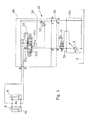
- Figures 1 to 6 show a hydraulic supply system 1 of a tractor comprising:
- valve manifold 10 comprises first valve assembly 20 which is directly connected to pump 2 and tank 3, and final valve assembly 40 which closes or redirects ports.
- intermediate valve assemblies 30 are provided to control fluid flow to consumers (not shown) on the tractor (e.g. linkage cylinders) or on an implement (via respective couplings which are not shown).
- Valve assemblies 20, 30, 40 are provided with shared ports which are named P for the ports connected to pump 2, R for the ports connected to tank 3 and Y for the ports connected to LS signal lines.
- exit ports A, B are for connection with the hydraulic lifting cylinders 4, e.g. port A may be connected to piston side 4a and port B may be connected to the opposing (annular) side 4b of the piston.
- valve manifold 10 can be designed without internal connecting pipes or hoses and is very flexible in terms of the configurations which may be achieved.
- An example of such a manifold is the SB23 Control Block produced by Bosch Rexroth AG of Schwieberdingen, Germany.
- valve assembly 20 provides connection to the aligned ports P, R, Y.
- a fixed displacement pump may be installed requiring different first valve assembly 20 including means to keep pressure differential constant and to provide the aligned ports P, R, Y.
- Final valve assembly 40 is provided to close or redirect the ports. Ports not used can be closed with locking screws.
- the first valve assembly 20 may be designed in that further intermediate valve assemblies can be attached on opposing sides as shown in applicant's published patent application EP 2472162A1 .
- Charge valve 5 is provided to short circuit the pump 2 for e.g. heating the oil circuit or loading the accumulator of an axle suspension system (not shown). In position 5a, the pump pressure is directly fed back to the pump adjustment so that the pump is at maximum delivery as long as position 5a is kept. Position 5b provides normal operation. Charge valve 5 may be optional but is required for some embodiments of the invention.
- valve assembly 30 comprises (in addition to other components not relevant for the invention and thereby not shown for better clarity) a control valve 31 for double-acting cylinder control.
- the control valve 31 has four positions (adjusted by solenoid and spring load) including intermediate positions:
- Piston side 4a is connected to pump 2.
- the load required to lift an implement is fed back via port 31 Y so that pump 2 is adjusted.
- the annular side 4b is connected to tank.
- Annular side 4b is connected to pump 2. In this position the piston side 4a is connected to tank.
- Piston side 4a and annular side 4b are connected to tank 3 and LS port 31 Y so that the linkage can freely move when external loads are applied e.g. during soil work.
- Piston side 4a and annular side 4b are blocked for road operation.
- the linkage is kept in position. This position is also the default setting when the solenoids are disconnected (e.g. by cable break).
- spool valves are characterised by the fact that, even in a closed position 31 d, fluid can pass through the gaps between spool and housing, a check valve 31 e is an integral part of control valve 31 to ensure seat tightness.
- Check valve 31 e is controlled with the spool so that the check valve is opened or closed depending on valve position - for example in position 31 b and 31 c the check valve must be opened to allow fluid flow to tank 3.
- Both lines to piston and annular side 4a, 4b may be equipped with such a valve so that no unintended movement is possible e.g. when the tractor is lifted up by the linkage for tyre changing.
- valve assembly 30 is equipped with a shuttle valve 32 which ensures that the highest load sensing signal is forwarded for pump adjustment. This is especially needed if many valve assemblies 30 are installed.
- Charge valve 5 is optional in this arrangement.
- valve assembly 30 comprises means for single-acting cylinder control.
- This circuit enables the similar four positions (adjusted by solenoid and spring load) including intermediate positions, whereby these positions depend on the adjustment of a control valve 33 (with positions 33a/b) and lock valve 34 (with positions 34a/b).
- annular side 4b is constantly connected to tank 3, and the load sensing LS signal is fed back to adjust pump displacement after (downstream of) control valve 33.
- Control valve 33 is in position 33a so that piston side 4a is connected to pump 2.
- Lock valve 34 is in position 34a. Fluid on annular side 4b is discharged to tank 3 as piston side 4a fills.
- Control valve 33 is in position 33b and check valve 35 prevents any fluid from the cylinder 4 passing to the tank 3 via valve 33. Only the load sensing LS signal is discharged via valve 33. Lock valve 34 is in position 34b so that piston side 4a is connected to tank 3. Fluid can flow into annular side 4b as the lowering action causes it to be sucked from tank 3.
- Control valve 33 is in position 33b and lock valve 34 is in position 34a, no discharge from piston side 4a to tank is possible.
- the cylinder position is kept (for road travel). Consequently, external forces cannot pull the linkage (and thereby the piston) downwards, but upwards movement (caused by external forces) is possible as fluid would then be sucked from the tank.
- the Locking position is kept if solenoid control cable break occurs for valves 33 and 34, or if the tractor is shut down, due to spring load on the valve spools.
- valve assembly 30 is equipped with a shuttle valve 32 which ensures that the highest load sensing signal is forwarded for pump adjustment. This is especially needed if many valve assemblies 30 are installed.
- a pressure limiting valve 36 prevents pressure levels above 230 bar which may occur e.g in locking position when travelling along a uneven road when the implements start to swing, or in any position wherein the external load exceeds maximum system pressure (defined by pump being 200 bar).
- Charge valve 5 is optional in this arrangement.
- valves 33 and 34 of Figure 2a are merged into one control valve 37 still providing for single-acting cylinder control.
- Control valve 37 If Control valve 37 is in position 37c no discharge of piston side 4a to tank is possible. External forces cannot pull the piston (and thereby the linkage) upwards, as fluid cannot be sucked from tank.
- This locking position is also taken in case of control cable break (with the valve spool centred at 37c by two springs).
- valve assembly 30 is equipped with a shuttle valve 32 which ensures that the highest load sensing signal is forwarded for pump adjustment and, as in Figure 2a , a pressure limiting valve 36 prevents pressure levels exceeding 230 bar.
- Check valve 38 (between the piston side 4a and control valve 37) is also moved by the spool of valve 37 to open the connection to tank 3 e.g. in position 37b.
- Charge valve 5 is optional in this arrangement.
- FIG 3 shows an obvious but undesired approach to solving the problem of providing double-acting functionality to an existing single-acting system.
- a valve 50 is added to selectively assign valve assembly 30 (including valves 33, 34 , 35 from Figure 2b ) to piston side 4a or annular side 4b.
- This approach would enable a modular upgrade of single-acting to double-acting control but shows one major disadvantage referring to operational safety.
- valve 50 In case of cable break at valve 50, the spring of valve 50 can only adjust to one position 50a or 50b, depending which on valve configuration is the spring loaded default. In consequence, one of piston side 4a or annular side 4b would permanently be connected to pump 2 while the opposing side is permanently connected to tank so if the delivery of pump 2 is increased by demand of a further consumer (not shown) via the load sensing circuit, this would result in undesired movement of the linkage in an upwards or downwards direction.
- valve 51 providing a central locking position 51 a may be installed in place of valve 50.
- this requires two solenoids to be controlled, increasing costs, and still fluid can pass through spool gaps such that unintended or undesired movement cannot be prohibited.
- Charge valve 5 is optional in this arrangement.
- Figure 4 shows a first embodiment of a solution according to the present invention, wherein a conversion apparatus includes a pressure piloted lockable check valve 60 and control valve 61 which is added beside the existing valve assembly 30 to provide a modular upgrade of the single-acting control to a double-acting control.
- the apparatus further includes a first fluid connection 57 from the pump upstream (i.e. on the pump side) of the valve assembly 30 to the control valve 61.
- a second fluid connection 58a - 58b is provided by the control valve 61 for connection of the annular side 4b to the tank 3.
- a third fluid connection 59 links a connection between the control valve 61 and check valve 60 with the load sensing LS circuit of the vehicle.
- Control valve 61 is connected to pump 2 (via connection 57) and tank 3 by respective ports: two further connections couple the valve 61 to a main port and unlocking port of the check valve 60.
- position 61 a the annular side 4b is connected to pump 2 as lockable check valve 60 does not block the oil flow in the direction from pump to annular side 4b.
- position 61 b the connections within control valve 61 are reversed whereby the pump pressure unlocks lockable check valve 60 so that the annular side 4b is connected to tank 3.
- the pump pressure to unlock lockable check valve 60 must therefore be smaller than the stand-by-pressure of the pump to maintain responsiveness.
- the control of the piston side is similar to that described above with reference to Figure 2a , providing the respective four positions / Modes.
- Control valve 33 is in position 33a so that piston side 4a is connected to pump 2.
- Lock valve 34 is in position 34a.
- Control valve 61 is in position 61 b so that the annular side 4b is discharged to tank 3
- Control valve 33 is in position 33b and check valve 35 prevents any fluid from the cylinder 4 passing to the tank 3 via valve 33. Only the load sensing LS signal is discharged via valve 33. Lock valve 34 is in position 34b so that piston side 4a is connected to tank 3. Rather than fluid simply flowing into annular side 4b as the lowering action causes it to be sucked from tank 3, control valve 61 is in position 61 a so that the annular side 4b is connected to pump 2.
- Lock valve 34 is in position 34b so that piston side 4a is connected to tank 3.
- Control valve 61 is in position 61 b so that check valve 60 is unlocked and the annular side 4b is discharged to tank 3. With both piston side 4a and annular side 4b connected to tank 3 the linkage is free to move up and down.
- Control valve 33 is in position 33b and lock valve 34 is in position 34a, no discharge of piston side 4a to tank is possible.
- the cylinder position is kept (for road travel).
- control valve 61 is in position 61 a so that the annular side 4b is completely blocked by lockable check valve 60 and no movement of the pistons is possible.
- this configuration enables a safe state for both piston side 4a and annular side 4b.
- the piston side 4a is secured by valve assembly 30 while the conversion/upgrade elements 60 and 61 secure the annular side 4b.
- valve 61 In case of a cable break or the vehicle shut down, valve 61 would be biased by spring 61 e into position 61 a blocking the return to tank 3. In case of a cable break, control valve 61 can be adjusted and locked manually by lever 61 c to position 61 b so that the single-acting mode is prohibited mechanically in a safe state.
- Figure 5a shows a further embodiment with control valve 70 and check valve 71.
- the control means of the previous embodiment are only capable to adjust the oil flow (and thereby the speed and position of the linkage).
- Control valve 70 allows also the adjustment of the pressure in the annular side 4b which is advantageous for implements requiring a force downwards e.g. a stump grinder or a dozer blade.
- Check valve 71 provides a safe state for annular side 4b in the case of a cable break of control valve 70. In order that the pressure in the annular side 4b can be balanced by pilot line 70a, check valve 71 must be installed before (on the upstream/pump side of) the control valve 70 as a check valve between annular side 4b and control valve 70 would make discharge to tank impossible.
- Third fluid connection (as at 59 in Figure 4 ) for load sensing signal may be provided but has a disadvantage in some applications. If the tractor is lifted by pressurizing annular side 4b (so that linkage is forced downwards) the load of the tractor would also pressurize annular chamber 4b so a constant load sensing signal would be generated and the pump would constantly run at high performance which is not efficient during e.g. changing tyres.
- charge valve 5 is required.
- third fluid connection 59 is not present, so that the annular side 4b is not connected to the Load sensing signal and any demand would not result in a pump adjustment.
- the pump delivery is increased by charge valve 5 switched to position 5a (short circuit mode normally used to heat up the oil in winter).After lifting the tractor, the operator can then switch charge valve 5 back to position 5b so that the tyres can be changed in a more efficient condition.
- Figure 5b shows a further embodiment with control valve 70 and check valve 71 integrated in one control valve 72 providing the same function (including the involvement of charge valve 5) as described in Figure 5a .
- check valve means as used herein encompasses both a discrete check valve component (as at 71 in Figure 5a ) and the provision of check valve functionality in another valve component (as at 72a in the control valve 72 of Figure 5b ).
- the invention provides a modular upgrade of a single-acting linkage control.
- the additional means to upgrade the system can easily installed in between the valve manifold 10 and the respective cylinder or cylinders 4. Connection to pump or tank can also be easily integrated via first valve assembly 20 or final valve assembly 40 or at any place within the circuit. There is no impact on the design of valve manifold 10. This is especially advantageous for after-sales market and for low specification tractors where only a small percentage are required to be equipped with double-acting linkage control.
- Figure 6 shows a further embodiment with pressure piloted lockable check valve 60 and control valve 61.
- the control means are only capable to adjust the oil flow (and thereby the speed and position of the linkage) while the arrangement of Figure 6 offers pressure adjustment.
- the load sensing signal is fed back from the third fluid connection 59 via feedback line 61 d to control valve 61 resulting in a pressure level adjustment as described below.
- Solenoid 61f of the control valve initially adjusts the fluid pressure on the annular side 4b.
- This annular side pressure is generating the load sensing signal on line 59 and is also forwarded to the control valve 61.
- Figure 6 shows a preferred solution compared to Figures 5a , 5b in that it also provides pressure adjustment but is relatively simple and does not require the use of the charge valve 5.
- the two-position control valve 61 may be replaced by a three-position control valve (indicated at 62) again supplied with load sensing feedback on line 61 d but now with an intermediate position in which the pressure may be adjusted more precisely.
- Figure 7 shows a modification to the embodiment of Figure 6 in which a shuttle valve 63 is provided to compare the pressure on piston side 4a and annular side 4b.
- the operator can adjust a pressure on the annular side to e.g. 200 bar. Due to the cylinder ratio between piston surface and annular surface of say 1.3, the pressure on the piston side would be 153 bar. This pressure is superimposed by a pressure caused by the implement weight of e.g. 80 bar, giving a pressure at the piston side 4a of 233 bar. This would result in pressure limiting valve 36 opening and piston side 4a would be connected to tank 3. As a consequence, the cylinder 4 would be inadvertently lowered.
- Shuttle valve 63 mitigates this problem in that the pressure of the piston side 4a being higher then 200 bar would move valve 61 in position 61 b so that annular side 4b is discharged to tank. Thereby, the pump 2 is not constantly delivering against pressure limiting valve 36 with 230 bar which is more efficient.
- a further pressure limiting valve 64 is introduced in the line between piston side 4a and shuttle valve 63.
- the pressure limiting valve 64 is operates differently.
- Pressure limiting valve 36 opens the connection depending on the pressure difference between port 36a and 36b.
- pressure on port 36b is 0 bar so that the pressure difference only depends on the pressure at port 36a.
- pressure limiting valve 64 is designed so that the valve position only depends on the pressure at port 64a.
- the pressure limiting valve 64 valves opens at 200 bar charged on port 64a independent on the pressure on port 64b which is not connected to tank so that the pressure can vary.
- shuttle valve 63 and pressure limiting valve 64 could also be used with the embodiments shown in Figure 5a or 5b .
- the embodiments of Figures 4 to 7 may additionally be equipped with a pressure sensor 75.
- This sensor may be used to monitor the pressure on the piston side.
- This sensor may be used for linkage control as described in the applicants co-pending application WO2013/053645 .
- the sensor could be used to detect whether pressure on annular side (decreased by cylinder ratio) plus pressure caused by weight of the implement causes an overpressure not released to tank so that the pressure limiting valve 36 constantly discharges fluid to tank, which is inefficient.
- the sensor could give a warning signal in this event.
- sensor 75 can also be used to detect if the implement touches the ground. This is of use e.g. when the rear axle of the tractor should be raised to lift the rear wheels clear of the ground to change the tyres.
- a lower pressure on annular side 4b
- the weight of the implement is added to this pressure.
- the linkage touches ground the weight of the implement is borne by the ground so that the pressure shown at sensor 75 is lower as only the pressure adjusted at annular side 4b (decreased by cylinder ratio) would be shown. Knowing this the pressure on annular side 4b can then be increased to bear the weight of the tractor. In this manner, the linkage is lowered slowly, avoiding accidents, and can then be switched to more powerful operation to lift the tractor. This is also more efficient.
Landscapes
- Engineering & Computer Science (AREA)
- Physics & Mathematics (AREA)
- Fluid Mechanics (AREA)
- Mechanical Engineering (AREA)
- General Engineering & Computer Science (AREA)
- Chemical & Material Sciences (AREA)
- Analytical Chemistry (AREA)
- Fluid-Pressure Circuits (AREA)
Applications Claiming Priority (1)
| Application Number | Priority Date | Filing Date | Title |
|---|---|---|---|
| GB201319154A GB201319154D0 (en) | 2013-10-30 | 2013-10-30 | Hydraulic system supply |
Publications (1)
| Publication Number | Publication Date |
|---|---|
| EP2884118A1 true EP2884118A1 (de) | 2015-06-17 |
Family
ID=49767379
Family Applications (1)
| Application Number | Title | Priority Date | Filing Date |
|---|---|---|---|
| EP14187181.4A Withdrawn EP2884118A1 (de) | 2013-10-30 | 2014-09-30 | Hydraulisches Versorgungssystem |
Country Status (2)
| Country | Link |
|---|---|
| EP (1) | EP2884118A1 (de) |
| GB (1) | GB201319154D0 (de) |
Cited By (7)
| Publication number | Priority date | Publication date | Assignee | Title |
|---|---|---|---|---|
| EP3171039A1 (de) * | 2015-11-18 | 2017-05-24 | HAWE Hydraulik SE | Hydraulisches hubmodul mit hebe- und senkfunktion |
| EP3321515A1 (de) * | 2016-11-09 | 2018-05-16 | AGCO International GmbH | Hydraulikzylinderversorgungssystem |
| EP3530962A1 (de) | 2018-02-27 | 2019-08-28 | Robert Bosch GmbH | Verfahren zur steuerung eines senkendrucks eines elektrohydraulischen krafthebers und elektrohydraulischer kraftheber |
| EP3569871A1 (de) * | 2018-05-15 | 2019-11-20 | AGCO International GmbH | Hydraulikzylinderversorgungssystem |
| DE102020208922B3 (de) | 2020-07-16 | 2021-12-09 | Robert Bosch Gesellschaft mit beschränkter Haftung | Ventilanordnung |
| EP3985264A1 (de) | 2020-10-15 | 2022-04-20 | Robert Bosch GmbH | Anordnung und verfahren zur ansteuerung eines hubwerkes |
| IT202100002648A1 (it) * | 2021-02-05 | 2022-08-05 | Cnh Ind Italia Spa | Veicolo agricolo o da lavoro dotato di un sollevatore idraulico |
Citations (5)
| Publication number | Priority date | Publication date | Assignee | Title |
|---|---|---|---|---|
| US3851566A (en) * | 1973-01-13 | 1974-12-03 | Bosch Gmbh Robert | Apparatus for controlling a hydraulic-lift tail gate arrangement of a cargo-carrying vehicle |
| US20040177749A1 (en) * | 2003-03-10 | 2004-09-16 | Sauer-Danfoss (Nordborg) A/S | Driving device, particularly lifting device for a working vehicle |
| US20040237768A1 (en) * | 2003-05-28 | 2004-12-02 | Barber Dennis R. | Hydraulic control valve assembly having dual directional spool valves with pilot operated check valves |
| US20090050222A1 (en) * | 2007-08-20 | 2009-02-26 | Hydraforce, Inc. | Three-way poppet valve with intermediate pilot port |
| EP2466152A1 (de) * | 2010-12-17 | 2012-06-20 | HAWE Hydraulik SE | Elektrohydraulische Steuervorrichtung |
-
2013
- 2013-10-30 GB GB201319154A patent/GB201319154D0/en not_active Ceased
-
2014
- 2014-09-30 EP EP14187181.4A patent/EP2884118A1/de not_active Withdrawn
Patent Citations (5)
| Publication number | Priority date | Publication date | Assignee | Title |
|---|---|---|---|---|
| US3851566A (en) * | 1973-01-13 | 1974-12-03 | Bosch Gmbh Robert | Apparatus for controlling a hydraulic-lift tail gate arrangement of a cargo-carrying vehicle |
| US20040177749A1 (en) * | 2003-03-10 | 2004-09-16 | Sauer-Danfoss (Nordborg) A/S | Driving device, particularly lifting device for a working vehicle |
| US20040237768A1 (en) * | 2003-05-28 | 2004-12-02 | Barber Dennis R. | Hydraulic control valve assembly having dual directional spool valves with pilot operated check valves |
| US20090050222A1 (en) * | 2007-08-20 | 2009-02-26 | Hydraforce, Inc. | Three-way poppet valve with intermediate pilot port |
| EP2466152A1 (de) * | 2010-12-17 | 2012-06-20 | HAWE Hydraulik SE | Elektrohydraulische Steuervorrichtung |
Cited By (11)
| Publication number | Priority date | Publication date | Assignee | Title |
|---|---|---|---|---|
| EP3171039A1 (de) * | 2015-11-18 | 2017-05-24 | HAWE Hydraulik SE | Hydraulisches hubmodul mit hebe- und senkfunktion |
| EP3321515A1 (de) * | 2016-11-09 | 2018-05-16 | AGCO International GmbH | Hydraulikzylinderversorgungssystem |
| EP3530962A1 (de) | 2018-02-27 | 2019-08-28 | Robert Bosch GmbH | Verfahren zur steuerung eines senkendrucks eines elektrohydraulischen krafthebers und elektrohydraulischer kraftheber |
| EP3569871A1 (de) * | 2018-05-15 | 2019-11-20 | AGCO International GmbH | Hydraulikzylinderversorgungssystem |
| US10760594B2 (en) | 2018-05-15 | 2020-09-01 | Agco International Gmbh | Hydraulic cylinder supply system |
| DE102020208922B3 (de) | 2020-07-16 | 2021-12-09 | Robert Bosch Gesellschaft mit beschränkter Haftung | Ventilanordnung |
| EP3940246A1 (de) | 2020-07-16 | 2022-01-19 | Robert Bosch GmbH | Ventilanordnung und verfahren zur ansteuerung eines hubwerks oder anbaugeräts |
| EP3985264A1 (de) | 2020-10-15 | 2022-04-20 | Robert Bosch GmbH | Anordnung und verfahren zur ansteuerung eines hubwerkes |
| DE102020213039A1 (de) | 2020-10-15 | 2022-04-21 | Robert Bosch Gesellschaft mit beschränkter Haftung | Anordnung und Verfahren zur Ansteuerung eines Hubwerkes |
| IT202100002648A1 (it) * | 2021-02-05 | 2022-08-05 | Cnh Ind Italia Spa | Veicolo agricolo o da lavoro dotato di un sollevatore idraulico |
| EP4039072A1 (de) * | 2021-02-05 | 2022-08-10 | CNH Industrial Italia S.p.A. | Landwirtschaftliches fahrzeug oder arbeitsfahrzeug mit einer hydraulischen hebevorrichtung |
Also Published As
| Publication number | Publication date |
|---|---|
| GB201319154D0 (en) | 2013-12-11 |
Similar Documents
| Publication | Publication Date | Title |
|---|---|---|
| EP2884118A1 (de) | Hydraulisches Versorgungssystem | |
| US20090308068A1 (en) | Control circuit for construction machine | |
| GB2487463A (en) | System for operating a hydraulic cylinder, including a directional control valve and a selective check valve | |
| EP2857695B1 (de) | Auslegerantriebsvorrichtung für eine baumaschine | |
| EP1764339B1 (de) | Hydraulische Anordnung für einen an einem Fahrzeug schwenkbar gelagerten Auslegerarm | |
| US10760594B2 (en) | Hydraulic cylinder supply system | |
| US11713775B2 (en) | Agricultural implements and hydraulic circuits therefor incorporating one or more priority valves | |
| US9932996B2 (en) | Electrohydraulic implement pressure cutoff | |
| US10066644B2 (en) | Forestry grapple with high pressure protection system | |
| US10820470B2 (en) | Hydraulic system for an agricultural implement incorporating implement-based hydraulic load sensing | |
| EP2910796B1 (de) | Anordnung mit einer Steuerventileinrichtung mit einer Schwimmstellung | |
| US9272888B2 (en) | Machine and method of manufacturing a machine | |
| US20040000228A1 (en) | Pressure-Compensated hydraulic circuit with regeneration | |
| US10798866B2 (en) | Depth control system for raising and lowering a work unit of an implement | |
| JP5832193B2 (ja) | 作業機のアンロード装置 | |
| EP3321515A1 (de) | Hydraulikzylinderversorgungssystem | |
| KR102297031B1 (ko) | 트랙터 링크장치의 기울기 조절장치 | |
| US11654815B2 (en) | Closed center hoist valve with snubbing | |
| EP3599382B1 (de) | Hydrauliksystem und verfahren zur steuerung der geschwindigkeit und des drucks eines hydraulikzylinders | |
| US20230354733A1 (en) | Hydraulic adjustment device | |
| CN113574283B (zh) | 用于液压回路的再生阀 | |
| EP2878829A1 (de) | Hydraulisches Druckversorgungssystem | |
| JP2024049212A (ja) | 作業機械および作業機械の制御方法 | |
| KR20230149633A (ko) | 작업차량의 작업기 승강 제어 장치 | |
| JP2022184600A (ja) | コントロールバルブユニット |
Legal Events
| Date | Code | Title | Description |
|---|---|---|---|
| PUAI | Public reference made under article 153(3) epc to a published international application that has entered the european phase |
Free format text: ORIGINAL CODE: 0009012 |
|
| 17P | Request for examination filed |
Effective date: 20140930 |
|
| AK | Designated contracting states |
Kind code of ref document: A1 Designated state(s): AL AT BE BG CH CY CZ DE DK EE ES FI FR GB GR HR HU IE IS IT LI LT LU LV MC MK MT NL NO PL PT RO RS SE SI SK SM TR |
|
| AX | Request for extension of the european patent |
Extension state: BA ME |
|
| R17P | Request for examination filed (corrected) |
Effective date: 20151217 |
|
| RBV | Designated contracting states (corrected) |
Designated state(s): AL AT BE BG CH CY CZ DE DK EE ES FI FR GB GR HR HU IE IS IT LI LT LU LV MC MK MT NL NO PL PT RO RS SE SI SK SM TR |
|
| STAA | Information on the status of an ep patent application or granted ep patent |
Free format text: STATUS: THE APPLICATION IS DEEMED TO BE WITHDRAWN |
|
| 18D | Application deemed to be withdrawn |
Effective date: 20151218 |