EP2883988B1 - Artificial turf for landscape and sports - Google Patents
Artificial turf for landscape and sports Download PDFInfo
- Publication number
- EP2883988B1 EP2883988B1 EP13197271.3A EP13197271A EP2883988B1 EP 2883988 B1 EP2883988 B1 EP 2883988B1 EP 13197271 A EP13197271 A EP 13197271A EP 2883988 B1 EP2883988 B1 EP 2883988B1
- Authority
- EP
- European Patent Office
- Prior art keywords
- fibers
- layer
- artificial turf
- mechanically bounded
- mechanically
- Prior art date
- Legal status (The legal status is an assumption and is not a legal conclusion. Google has not performed a legal analysis and makes no representation as to the accuracy of the status listed.)
- Active
Links
- 239000000835 fiber Substances 0.000 claims description 168
- 244000025254 Cannabis sativa Species 0.000 claims description 22
- 238000004080 punching Methods 0.000 claims description 18
- 238000000034 method Methods 0.000 claims description 14
- 229920002994 synthetic fiber Polymers 0.000 claims description 14
- 239000000463 material Substances 0.000 claims description 12
- 239000012209 synthetic fiber Substances 0.000 claims description 12
- 238000004873 anchoring Methods 0.000 claims description 11
- 239000004744 fabric Substances 0.000 claims description 11
- 230000007423 decrease Effects 0.000 claims description 6
- 238000004519 manufacturing process Methods 0.000 claims description 6
- 229920000098 polyolefin Polymers 0.000 claims description 2
- 230000002708 enhancing effect Effects 0.000 claims 1
- 239000010410 layer Substances 0.000 description 128
- -1 polypropylene Polymers 0.000 description 9
- 239000004698 Polyethylene Substances 0.000 description 7
- 229920000573 polyethylene Polymers 0.000 description 7
- 230000000694 effects Effects 0.000 description 6
- 239000000203 mixture Substances 0.000 description 6
- 239000004745 nonwoven fabric Substances 0.000 description 6
- 239000004576 sand Substances 0.000 description 5
- 239000002689 soil Substances 0.000 description 5
- 239000004743 Polypropylene Substances 0.000 description 4
- 238000005452 bending Methods 0.000 description 4
- 229920001155 polypropylene Polymers 0.000 description 4
- 239000002356 single layer Substances 0.000 description 4
- 239000000758 substrate Substances 0.000 description 4
- 238000009732 tufting Methods 0.000 description 4
- 238000002835 absorbance Methods 0.000 description 3
- 229920001971 elastomer Polymers 0.000 description 3
- 229920000728 polyester Polymers 0.000 description 3
- 239000005060 rubber Substances 0.000 description 3
- XLYOFNOQVPJJNP-UHFFFAOYSA-N water Substances O XLYOFNOQVPJJNP-UHFFFAOYSA-N 0.000 description 3
- 240000000491 Corchorus aestuans Species 0.000 description 2
- 235000011777 Corchorus aestuans Nutrition 0.000 description 2
- 235000010862 Corchorus capsularis Nutrition 0.000 description 2
- 239000004952 Polyamide Substances 0.000 description 2
- 230000002745 absorbent Effects 0.000 description 2
- 239000002250 absorbent Substances 0.000 description 2
- 239000000853 adhesive Substances 0.000 description 2
- 230000001070 adhesive effect Effects 0.000 description 2
- 210000002421 cell wall Anatomy 0.000 description 2
- 238000005516 engineering process Methods 0.000 description 2
- 239000004746 geotextile Substances 0.000 description 2
- 239000004816 latex Substances 0.000 description 2
- 229920000126 latex Polymers 0.000 description 2
- 229920002647 polyamide Polymers 0.000 description 2
- 239000000843 powder Substances 0.000 description 2
- 230000035939 shock Effects 0.000 description 2
- 239000002352 surface water Substances 0.000 description 2
- 239000002759 woven fabric Substances 0.000 description 2
- 229920000742 Cotton Polymers 0.000 description 1
- 241000196324 Embryophyta Species 0.000 description 1
- 239000004831 Hot glue Substances 0.000 description 1
- 241000446313 Lamella Species 0.000 description 1
- 241001465754 Metazoa Species 0.000 description 1
- 239000004677 Nylon Substances 0.000 description 1
- 229920000297 Rayon Polymers 0.000 description 1
- 239000012963 UV stabilizer Substances 0.000 description 1
- 239000011230 binding agent Substances 0.000 description 1
- 239000011248 coating agent Substances 0.000 description 1
- 238000000576 coating method Methods 0.000 description 1
- 238000005056 compaction Methods 0.000 description 1
- 239000002131 composite material Substances 0.000 description 1
- 238000010276 construction Methods 0.000 description 1
- 229920001577 copolymer Polymers 0.000 description 1
- 239000000839 emulsion Substances 0.000 description 1
- 230000003628 erosive effect Effects 0.000 description 1
- 238000009950 felting Methods 0.000 description 1
- 239000013305 flexible fiber Substances 0.000 description 1
- 239000008187 granular material Substances 0.000 description 1
- 230000002363 herbicidal effect Effects 0.000 description 1
- 239000004009 herbicide Substances 0.000 description 1
- 238000007757 hot melt coating Methods 0.000 description 1
- 229910052500 inorganic mineral Inorganic materials 0.000 description 1
- 238000003780 insertion Methods 0.000 description 1
- 230000037431 insertion Effects 0.000 description 1
- 230000002262 irrigation Effects 0.000 description 1
- 238000003973 irrigation Methods 0.000 description 1
- 238000010030 laminating Methods 0.000 description 1
- 238000010297 mechanical methods and process Methods 0.000 description 1
- 230000005226 mechanical processes and functions Effects 0.000 description 1
- 239000012528 membrane Substances 0.000 description 1
- 230000003278 mimic effect Effects 0.000 description 1
- 239000011707 mineral Substances 0.000 description 1
- 238000012986 modification Methods 0.000 description 1
- 230000004048 modification Effects 0.000 description 1
- 229920003052 natural elastomer Polymers 0.000 description 1
- 229920001194 natural rubber Polymers 0.000 description 1
- 229920001778 nylon Polymers 0.000 description 1
- 239000002245 particle Substances 0.000 description 1
- 230000035515 penetration Effects 0.000 description 1
- 229920000139 polyethylene terephthalate Polymers 0.000 description 1
- 239000005020 polyethylene terephthalate Substances 0.000 description 1
- 229920000642 polymer Polymers 0.000 description 1
- 239000002964 rayon Substances 0.000 description 1
- 229920005989 resin Polymers 0.000 description 1
- 230000006641 stabilisation Effects 0.000 description 1
- 238000011105 stabilization Methods 0.000 description 1
- 229920003051 synthetic elastomer Polymers 0.000 description 1
- 239000000057 synthetic resin Substances 0.000 description 1
- 239000005061 synthetic rubber Substances 0.000 description 1
- 239000004753 textile Substances 0.000 description 1
- 229920001169 thermoplastic Polymers 0.000 description 1
- 239000004416 thermosoftening plastic Substances 0.000 description 1
- 238000009966 trimming Methods 0.000 description 1
- 239000002699 waste material Substances 0.000 description 1
- 210000002268 wool Anatomy 0.000 description 1
Images

Classifications
-
- D—TEXTILES; PAPER
- D04—BRAIDING; LACE-MAKING; KNITTING; TRIMMINGS; NON-WOVEN FABRICS
- D04H—MAKING TEXTILE FABRICS, e.g. FROM FIBRES OR FILAMENTARY MATERIAL; FABRICS MADE BY SUCH PROCESSES OR APPARATUS, e.g. FELTS, NON-WOVEN FABRICS; COTTON-WOOL; WADDING ; NON-WOVEN FABRICS FROM STAPLE FIBRES, FILAMENTS OR YARNS, BONDED WITH AT LEAST ONE WEB-LIKE MATERIAL DURING THEIR CONSOLIDATION
- D04H11/00—Non-woven pile fabrics
- D04H11/08—Non-woven pile fabrics formed by creation of a pile on at least one surface of a non-woven fabric without addition of pile-forming material, e.g. by needling, by differential shrinking
-
- D—TEXTILES; PAPER
- D05—SEWING; EMBROIDERING; TUFTING
- D05C—EMBROIDERING; TUFTING
- D05C17/00—Embroidered or tufted products; Base fabrics specially adapted for embroidered work; Inserts for producing surface irregularities in embroidered products
- D05C17/02—Tufted products
-
- D—TEXTILES; PAPER
- D06—TREATMENT OF TEXTILES OR THE LIKE; LAUNDERING; FLEXIBLE MATERIALS NOT OTHERWISE PROVIDED FOR
- D06N—WALL, FLOOR, OR LIKE COVERING MATERIALS, e.g. LINOLEUM, OILCLOTH, ARTIFICIAL LEATHER, ROOFING FELT, CONSISTING OF A FIBROUS WEB COATED WITH A LAYER OF MACROMOLECULAR MATERIAL; FLEXIBLE SHEET MATERIAL NOT OTHERWISE PROVIDED FOR
- D06N7/00—Flexible sheet materials not otherwise provided for, e.g. textile threads, filaments, yarns or tow, glued on macromolecular material
- D06N7/0063—Floor covering on textile basis comprising a fibrous top layer being coated at the back with at least one polymer layer, e.g. carpets, rugs, synthetic turf
- D06N7/0065—Floor covering on textile basis comprising a fibrous top layer being coated at the back with at least one polymer layer, e.g. carpets, rugs, synthetic turf characterised by the pile
-
- D—TEXTILES; PAPER
- D06—TREATMENT OF TEXTILES OR THE LIKE; LAUNDERING; FLEXIBLE MATERIALS NOT OTHERWISE PROVIDED FOR
- D06N—WALL, FLOOR, OR LIKE COVERING MATERIALS, e.g. LINOLEUM, OILCLOTH, ARTIFICIAL LEATHER, ROOFING FELT, CONSISTING OF A FIBROUS WEB COATED WITH A LAYER OF MACROMOLECULAR MATERIAL; FLEXIBLE SHEET MATERIAL NOT OTHERWISE PROVIDED FOR
- D06N7/00—Flexible sheet materials not otherwise provided for, e.g. textile threads, filaments, yarns or tow, glued on macromolecular material
- D06N7/0063—Floor covering on textile basis comprising a fibrous top layer being coated at the back with at least one polymer layer, e.g. carpets, rugs, synthetic turf
- D06N7/0068—Floor covering on textile basis comprising a fibrous top layer being coated at the back with at least one polymer layer, e.g. carpets, rugs, synthetic turf characterised by the primary backing or the fibrous top layer
-
- E—FIXED CONSTRUCTIONS
- E01—CONSTRUCTION OF ROADS, RAILWAYS, OR BRIDGES
- E01C—CONSTRUCTION OF, OR SURFACES FOR, ROADS, SPORTS GROUNDS, OR THE LIKE; MACHINES OR AUXILIARY TOOLS FOR CONSTRUCTION OR REPAIR
- E01C13/00—Pavings or foundations specially adapted for playgrounds or sports grounds; Drainage, irrigation or heating of sports grounds
- E01C13/08—Surfaces simulating grass ; Grass-grown sports grounds
Landscapes
- Engineering & Computer Science (AREA)
- Textile Engineering (AREA)
- Architecture (AREA)
- Civil Engineering (AREA)
- Structural Engineering (AREA)
- Road Paving Structures (AREA)
Description
- The present invention relates to surfaces simulating natural grass and, more specifically, to artificial turf imitating the volume effect and density of natural grass and manufacturing such turf.
- Artificial turf, also often referred to as synthetic grass, is a surface of synthetic fibers made to look like natural grass. It is most often used in sports applications. However, it is now being used on residential lawns and landscaping as well. Artificial turf stands up to heavy use and requires no irrigation or trimming. Domed, covered, and partially covered stadiums may require artificial turf because of the difficulty of getting grass enough sunlight to stay healthy. But, artificial turfs currently available still fail to provide the excellent shock absorbing properties of natural grass surfaces and also fall short in mimicking the volume effect of natural grass.
- Today's generation artificial turfs are typically made from UV-enhanced polypropylene fiber or polyethylene fiber that is tufted into a woven synthetic primary backing that receives a secondary backing in form of a coating or laminate on the opposite side of the face fibers to give the turf dimensional stability and to aid fiber binding.
- When installed, the turf's face (i.e., the grass "blades") is generally given a layer of sand to augment water drainage and/or a layer of cryogenic rubber granules to help keeping the tufts more vertically oriented and to provide shock-absorbency. The infill typically provides ballast and structure for the artificial turf, helping the fibers to stand and to provide a "cushion" effect when stepping over the turf. This protects the roots of the tuft fibers.
- Currently, non-infill artificial turf refers to those artificial turf models with short pile height, narrow gauge (distance between rows), and high stitch rate. Artificial turfs that are used without such infill are typically made from shorter, denser polyethylene fibers that include even shorter crimped fibers to keep the tufts resembling grass blades upright. Some non-infill systems provide an underlay under the turf to provide cushioning.
- Due to an ever increasing number of residential and commercial applications of artificial turf, artificial turf with improved properties that more and more resemble natural grass is sought after, as illustrated in the following examples.
-
GB 1,154,842 -
WO 2001/37657 A1 -
WO 2012/125513 A1 discloses a synthetic ground cover system for erosion control to be placed atop the ground, which includes a synthetic grass comprising a composite of one or more geo- textiles tufted with synthetic yarns. The synthetic ground cover also includes a sand/soil infill ballast applied to the synthetic grass and a binding agent applied to the sand/soil infill to stabilize the sand/soil infill against high velocity water shear forces. The system includes a synthetic turf which includes a backing and synthetic turf blades secured to the backing. The synthetic grass blades are tufted into the substrate or backing comprising a synthetic woven or non-woven fabric. The backing can be a single ply backing or can be a multi-ply backing, as desired. A filter can be secured to the substrate to reinforce the substrate and better secure the synthetic grass blades. Preferably, the at least one filter fabric may also comprise non-woven synthetic fabric. - As more artificial turf and less natural grass is used to cover the ground for an increasing number of applications, it is increasingly important to provide artificial turf that is eco-friendly.
- From the foregoing, it can be seen that there is a need for artificial turf that resembles more closely natural grass.
- The present invention seeks to provide artificial turf for landscape and sports applications that imitates more closely the root zone, the volume effect, and density of natural grass and that has an improved wear and drainage property.
- It is an advantage of embodiments of the present invention to provide the artificial turf with a mechanically bounded layer of fibers functioning as the root zone of natural grass that assists the pile yarn of the tufts to stand and that protects the bending points of the tufts such that the application of an infill can be eliminated. The mechanically bounded layer of fibers allows moving of the fiber so that compaction of the surface, thus hardening of the surface will be extensively be reduced.
- It is another advantage of embodiments of the present invention that the artificial turf can be made from materials that are entirely recyclable thereby reducing the amount of waste that presently has to be disposed of in landfills.
- It is still another advantage of embodiments of the present invention to enable surface water to drain easily in all directions to the ground underneath the installed artificial turf.
- It is yet another advantage of embodiments of the present invention to provide artificial turf with a mechanically bounded layer of fibers for equalizing for uneven/rocky soils.
- It is yet another advantage of embodiments of the present invention to provide artificial turf with a mechanically bounded layer of fibers that has shock absorbing properties and, thus, contributes to a more natural feeling of the artificial turf.
- According to an aspect of the present invention, an artificial turf adapted for use in landscape and sports applications comprises a mechanically bounded layer of fibers made of one or more natural and/or synthetic fibers. Pile yarn is inserted through the mechanically bounded layer of fibers, the pile yarn being anchored to the mechanically bounded layer of fibers. The mechanically bounded layer of fibers has a density that decreases from the bottom to the top of the mechanically bounded layer of fibers.
- By providing a mechanically bounded layer of fibers formed as a non-woven matting, surface water can drain easily to the soil underneath the artificial turf once installed. As a result, the artificial turf in accordance with advantageous embodiments of the present invention dries quickly provided drainage of the subsoil. By using a mixture of natural and, therefore, moisture absorbent fibers and synthetic fibers, the water holding capacity of the artificial turf can be improved compared to known prior art products.
- According to preferred embodiments of the present invention, decrease in density occurs at a constant rate. As a result, the layer provides structural support for the tufts and shock-absorbance to contribute to a more natural feeling of the artificial turf.
- According to preferred embodiments of the present invention, the mechanically bounded layer of fibers includes a lower layer and a upper layer, the lower layer being positioned at the bottom of the mechanically bounded layer of fibers and the upper layer being positioned on top of the lower layer, and the upper layer having a higher fiber coarseness than the lower layer.
- The terms "upper" and "top", on the one hand, and "lower" and "bottom", on the other hand, are used herein to designate sides or portions of the artificial turf with reference to their relative positioning when the turf is deployed for normal use on a ground surface. Thus, "upper" and "top" refer to portions at or near the side from which free ends of the tufts stick out; and "lower" and "bottom" refer to portions at or near the opposite side.
- This embodiment also provides structural support for the tufts and shock-absorbance to contribute to a natural feeling of the artificial turf, while allowing an efficient manufacturing process starting from two homogeneous non-woven mats having different fiber coarseness.
- According to preferred embodiments of the present invention, the lower layer provides structural support for the pile yarn.
- According to preferred embodiments of the present invention, the upper layer acts as a shock-absorbing layer and contributes to a natural feeling of the artificial turf.
- According to preferred embodiments of the present invention, the lower layer is formed by fibers that are more flexible and form a denser structure than fibers forming the upper layer, the fibers of the lower layer having a smaller linear mass density than fibers forming the upper layer.
- According to preferred embodiments of the present invention, the fibers of the lower layer have a linear mass density in the range of about 3,3 dtex to about 110 dtex.
- According to preferred embodiments of the present invention, wherein the fibers of the upper layer have a linear mass density in the range of about 11 dtex to about 600 dtex.
- According to preferred embodiments of the present invention, the upper layer is thicker and has a higher fiber coarseness than the lower layer.
- According to preferred embodiments of the present invention, fill yarn is created on the upper surface of the upper layer through velour needle-punching, the fill yarn giving the upper surface of the upper layer a velour-like appearance, thereby imitating the root zone of natural grass, providing cushioning, and assisting the pile yarn of the tufts to stand. By velour-needle punching the upper surface of the upper layer, the surface is given a fluffy structure that provides cushioning. Since the fill yarn assists the pile yarn to stand, no infill, as often used in the known prior art is needed with the artificial turf in accordance with advantageous embodiments of the present invention.
- According to preferred embodiments of the present invention, the mechanically bounded layer of fibers is manufactured as a single fabric or as two separate fabrics that are joined together.
- According to preferred embodiments of the present invention, the mechanically bounded layer of fibers is formed by needle-punching.
- According to preferred embodiments of the present invention, the mechanically bounded layer of fibers consists of up to eight different types of fibers.
- According to preferred embodiments of the present invention, the mechanically bounded layer of fibers, the pile yarn, and a backing anchoring the pile yarn to the mechanically bounded layer of fibers are made of eco-friendly materials that are 100% recyclable by being mechanically deconstructable. It is furthermore advantageous to choose a homogenous polymer composition for all elements of the inventive artificial turf to support the recyclability.
- According to an aspect of the present invention, a method for manufacturing artificial turf for use in landscape and sports applications comprises the steps of:
- forming by needle-punching a mechanically bounded layer of fibers having a density that decreases from the bottom to the top of the mechanically bounded layer of fibers; creating fill yarn extending from the upper surface of the mechanically bounded layer of fibers through velour needle-punching, thereby giving the upper surface of the mechanically bounded layer of fibers a velour-like appearance; inserting pile yarn through the mechanically bounded layer of fibers; and anchoring the pile yarn at the backside of the mechanically bounded layer of fibers.
- According to an aspect of the present invention, a method for manufacturing artificial turf for use in landscape and sports applications comprises the steps of: forming by needle-punching a lower layer from a plurality of natural and/or synthetic fibers; forming by needle-punching an upper layer from a plurality of natural and/or synthetic fibers that have a higher linear mass density than the fibers of the lower layer, the upper layer having a less dense structure than the lower layer; placing the upper layer on top of the lower layer to form a mechanically bounded layer of fibers; creating fill yarn on the upper surface of the upper layer through velour needle-punching thereby giving the upper surface of the upper layer a velour-like appearance; inserting pile yarn through the mechanically bounded layer of fibers; and anchoring the pile yarn at the backside of the mechanically bounded layer of fibers.
- The above and other characteristics, features, and advantages of the present invention will become apparent from the following detailed description, taken in conjunction with the accompanying drawings, which illustrate, by way of example, the principles of the invention. This description is given for the sake of example only, without limiting the scope of the invention. The reference figures quoted below refer to the attached drawings.
-
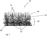
Fig. 1 is a schematic cross-sectional view of the artificial turf in accordance with a first preferred embodiment of the present invention; and -
Fig. 2 is a schematic cross-sectional view of the artificial turf in accordance with a second preferred embodiment of the present invention. - The present invention will be described with respect to particular embodiments and with reference to certain drawings but the invention is not limited thereto but only by the claims. Any reference signs in the claims shall not be construed as limiting the scope. The drawings described are only schematic and are non-limiting. In the drawings, the size of some of the elements may be exaggerated and not drawn on scale for illustrative purposes.
- Where the term "comprising" is used in the present description and claims, it does not exclude other elements or steps. Where an indefinite or definite article is used when referring to a singular noun e.g. "a" or "an", "the", this includes a plural of that noun unless something else is specifically stated.
- Reference throughout this specification to "one embodiment" or "an embodiment" means that a particular feature, structure, or characteristic described in connection with the embodiment is included in at least one embodiment of the present invention. Thus, appearances of the phrases "in one embodiment" or "in an embodiment" in various places throughout this specification are not necessarily all referring to the same embodiment, but may. Furthermore, the particular features, structures, or characteristics may be combined in any suitable manner, as would be apparent to one of ordinary skill in the art from this disclosure, in one or more embodiments.
- Similarly it should be appreciated that in the description of exemplary embodiments of the invention, various features of the invention are sometimes grouped together in a single embodiment, figure, or description thereof for the purpose of streamlining the disclosure and aiding in the understanding of one or more of the various inventive aspects. This method of disclosure, however, is not to be interpreted as reflecting an intention that the claimed invention requires more features than are expressly recited in each claim. Rather, as the following claims reflect, inventive aspects lie in less than all features of a single foregoing disclosed embodiment. Thus, the claims following the detailed description are hereby expressly incorporated into this detailed description, with each claim standing on its own as a separate embodiment of this invention.
- Furthermore, while some embodiments described herein include some but not other features included in other embodiments, combinations of features of different embodiments are meant to be within the scope of the invention, and form different embodiments, as would be understood by those in the art. For example, in the following claims, any of the claimed embodiments can be used in any combination.
- In the description provided herein, numerous specific details are set forth. However, it is understood that embodiments of the invention may be practiced without these specific details. In other instances, well-known methods, structures, and techniques have not been shown in detail in order not to obscure an understanding of this description.
- The following terms or definitions are provided solely to aid in the understanding of the invention.
- The term "backside" is used herein to denote the side of the mechanically bounded layer of fibers which faces away from the side from which free edges of the tufts stick out.
- As employed herein, the term "fiber coarseness" is defined as weight per fiber length and is normally expressed in units of mg/m or g/m. The fiber coarseness depends on fiber diameter, cell wall thickness, cell wall density, and fiber cross section. A high coarseness value indicates a thick fiber wall, giving stiff fibers unable to collapse. Thin walled fibers with low coarseness value give flexible fibers and a denser structure. The coarser the fibers, the stronger they will be.
- As employed herein, the term "tex" refers to a unit of measure for the linear mass density of fibers and is defined as the mass in grams per 1000 meters. The most commonly used unit is the decitex, abbreviated dtex, which is the mass in grams per 10,000 meters. When measuring objects that consist of multiple fibers the term "filament tex" is sometimes used, referring to the mass in grams per 1000 meters of a single filament.
- As employed herein, the term "tufting" refers to a type of textile process in which a thread is inserted on a carrier base. Tufted carpets are manufactured by insertion of tufts (a short cluster of elongates strands of yarn attached at the base) through a backing fabric, creating a pile surface of cut and/or loop ends.
- As employed herein, the term "filament" refers to a single continuous strand of natural or synthetic fiber.
- As employed herein, the term "yarn" refers to a continuous strand of twisted or untwisted threads of natural or synthetic material.
- As employed herein, the term "pile" refers to the visible surface (wearing surface) of carpet consisting of upright ends of yarn or yarn tufts in loop and/or cut configuration. Sometimes it is called "face" or "nap".
- As employed herein, the term "backing" refers to a substrate applied to the back of the carpet to increase dimensional stability and enhances the anchoring of the pile yarn.
- As employed herein, the term "non-woven" refers to engineered fabric (sheet or web structure) bonded together by entangling fibers mechanically, thermally, or chemically.
- As employed herein, the term "needle-punch" refers to a mechanical process involving thousands of needles that orient and interlock fibers to create nonwoven fabric.
- Referring to
Fig. 1 , the schematic cross-section of anartificial turf 10 is illustrated in accordance with preferred embodiments of the present invention. Theartificial turf 10 includes a mechanically bounded layer offibers 20, abacking 30, and a plurality oftufts 40. - The mechanically bounded layer of
fibers 20 is formed as a non-woven matting made of one or more natural and/or synthetic fibers or yarns. The mechanically bounded layer offibers 20 serves as a carrier for thetufts 40. - As illustrated in
Fig. 1 , the mechanically bounded layer offibers 20 can be a single layer containing a mixture of fibers. According to preferred embodiments of the present invention, the coarseness of the fibers forming the mechanically bounded layer offibers 20 may increase from the bottom to the top of thelayer 20. For example, the coarseness may gradually increase at a constant rate. - Alternatively, as illustrated in
Fig. 2 , the mechanically bounded layer offibers 20 can include visually two or more layers, such as, astructural layer 21 and avolume simulating layer 22. Thestructural layer 21 is positioned at the bottom of the mechanically bounded layer offibers 20 facing away from thepile yarn 41. Thevolume simulating layer 22 is positioned on top of thestructural layer 21 facing thepile yarn 41. In case of multiple layers of fibers, the mechanically bounded layer of fibers is divided into multiple functionalities, such as, for example, structural enhancements (layer 21) and volume simulating (layer 22). - The mechanically bounded layer of
fibers 20 can be manufactured as a single fabric or as two separate fabrics that are joined together. In accordance with preferred embodiment of the present invention, the mechanically bounded layer offibers 20 is formed by needle-punching. During this mechanical bonding method, fibers are transported with felting needles and interlocked in the non-woven structure. This procedure increases the friction between the fibers, which reinforces the non-woven fabric. To differentiate the structure of the non-woven fabric, the web can be further structured using special machines equipped with structuring fork or crown needles. The surface can be structured as a velour or rib, or with geometrical or linear patterns. Needle-punching is an ecologically friendly technology, as it permits the use of recycled material including that from polyethylene terephthalate bottles and regenerated fibers from apparel, as well as natural fibers. It may be possible to use other technologies to form non-woven fabrics to obtain the mechanically bounded layer offibers 20. - The mechanically bounded layer of
fibers 20 may consist of up to eight different types of fibers. Each of the fibers can have a different color, if desired. The types of fibers can include moisture absorbent fibers, such as coco, cotton, jute, wool, rayon or other natural or synthetic fibers. The types of fibers can further include synthetic fibers, such as polypropylene (PP), polyethylene (PE), polyamides (PA), and polyester (PES) or a combination thereof. The fibers can be treated, for example, with anti-algae, with herbicide, UV-stabilizer, or to be anti-static. The fibers can be melt fibers. The fibers can among others further include mineral based fibers, animal based fibers, or plant based fibers. - If the mechanically bounded layer of
fibers 20 is formed as a single layer, as shown inFig. 1 , a mixture of relatively thin walled fibers that are flexible and form a relatively dense structure and, thus, having a relatively low coarseness value and relatively thick walled fibers that are stiff and form a relatively sparse structure and, thus, having a relatively low coarseness value is used in combination. In an exemplary embodiment of the invention, the density of the mechanically bounded layer offibers 20 can gradually decrease from the bottom to the top of thelayer 20. Accordingly, the coarseness of the fibers will gradually increase from the bottom to the top of thelayer 20. By designing the mechanically bounded layer offibers 20 that way, structural support for thetufts 40 and protection for bendingpoints 42 of thetufts 40 is provided as well as shock-absorbance to contribute to a more natural feeling of theartificial turf 10. - If, according to preferred embodiments of the present invention, the mechanically bounded layer of
fibers 20 is formed as a single layer, as shown inFig. 2 , thestructural layer 21 is formed by relatively thin walled fibers that are flexible and form a relatively dense structure. Accordingly, fibers with the relatively low linear mass density (dtex value) are selected for thestructural layer 21. Thestructural layer 21 is utilized for anchoring thetufts 40. Thestructural layer 21 provides dimensional stability for theartificial turf 10 and protection for the bending points 42 of thetufts 40. The fibers of thestructural layer 21 have preferably a linear mass density in the range of about 3,3 dtex to about 110 dtex, and more preferably of about 11 dtex. - The
volume simulating layer 22 is formed by fibers having a larger linear mass density than the fibers of thestructural layer 21. The fibers of thevolume simulating layer 22 have preferably a linear mass density in the range of about 11 dtex to about 600 dtex, and more preferably of about 110 dtex. Consequently, thevolume simulating layer 22 has also a higher fiber coarseness (weight per fiber length) than thestructural layer 21. A high coarseness value indicates a thick fiber wall, giving stiff fibers unable to collapse. Therefore, thevolume simulating layer 22 of the mechanically bounded layer offibers 20 is thicker and coarser than thestructural layer 21. Fibers with a higher dtex value are selected for thevolume simulating layer 22 so that the mechanically bounded layer offibers 20 can act as a shock-absorbing layer and contribute to a natural feeling of theartificial turf 10. - In addition, the fibers of the mechanically bounded layer of
fibers 20 can be given a velour effect by needling to mimic the root zone volume effect of natural grass. Due to a mechanical needling process, fiber is pushed out of the upper surface of thelayer 20. Velour needle-punched non-woven material can be produced by placing an non-woven material on a brush-like stitch base and needling of the non-woven material on this stitch base. Since with this method the fibers seized by the needles are needled into the bristles or lamellas of the needle stitch base, the non-woven material needled in this way is given a velour-like appearance where the fiber stands out above the surface. - By velour needle-punching the mechanically bounded layer of
fibers 20, fillyarn 23 is created. Thefill yarn 23 is punched out of the non-woven fibrous matting of the mechanically bounded layer offibers 20 creating a natural grass like root zone . Thefill yarn 23 gives the upper surface of the mechanically bounded layer of fibers 20 (facing the pile yarn 41) a fluffy appearance and provide cushioning. Thefill yarn 23 also assists thepile yarn 41 of thetufts 40 to stand. Thus, no infill, as often used with prior art artificial turf, is needed with theartificial turf 10 in accordance with preferred embodiments of the present invention. - Strands of
pile yarn 41 form eachtuft 40. Atuft 40 is a short cluster of elongates strands ofpile yarn 41 attached at the base, thebending point 42. Thetufts 40 are inserted through the mechanically bounded layer offibers 20. Tufting usually is accomplished by inserting reciprocating needles threaded withpile yarn 41 into the mechanically bounded layer offibers 20 to formtufts 40 of yarn. Loopers or hooks, typically working in timed relationship with the needles, are located such that the loopers are positioned just above the needle eye when the needles are at an extreme point in their stroke through the mechanically bounded layer offibers 20. When the needles reach that point, pileyarn 41 is picked up from the needles by the loopers and held briefly. Loops ortufts 40 of yarn result from passage of the needles back through the mechanically bounded layer offibers 20. This process typically is repeated as the loops move away from the loopers due to advancement of the backing through the needling apparatus. Subsequent, the loops can be cut to form a cut pile, for example, by using a looper and knife combination in the tufting process to cut the loops. - The
pile yarn 41 can consist of up to four different types of yarns. Each yarn can have a different color, if desired. Thepile yarn 41 can be monofilament, tape or a combination thereof. Thepile yarn 41 has preferably a linear mass density of about 400 dtex to about 3000 dtex and, more preferably of about 1600 dtex. The number of strands ofpile yarn 41 in atuft 40 is between 2 and 10, and preferably 6. The tuft gauge (distance between rows) is between 1/2" and 1/16" and typical 3/8" or 3/16" or 1/8". The stitch rate of the tufting is between 8/10 cm and 30/10 cm and preferably 12/10 cm. - In accordance with preferred embodiments of the invention and as shown in
Fig. 2 , the mechanically bounded layer offibers 20 may have a height H3 of about 3 mm to about 15 mm, and more preferably about 8 mm. Thefill yarn 23 may extend from the upper surface of the mechanically bounded layer offibers 20 for a height H2 of about 1 mm to about 20 mm, and more preferably of about 10 mm. Thepile yarns 41 may extend from thefill yarn 23 for about 1 mm to about 20 mm, and more preferably 10 mm (height H1). The total height H4 of theartificial turf 10 may be about 10 mm to about 60 mm, and more preferably about 28 mm. - The
backing 30 is applied to the mechanically bounded layer offibers 20 as a last finishing step to enhance the anchoring of the tufts to the mechanically bounded layer offibers 20. In accordance with preferred embodiments of the present invention thebacking 30 can be a coated backing such as, for example, a polyethylene (PE) backing that is applied by means of powder or hot melt coating. Thebacking 30 can further be a calander backing or latex backing. - In the finishing operation, the backside or stitched surface of the mechanically bounded layer of
fibers 20 is coated with an adhesive, such as a natural or synthetic rubber or resin latex or emulsion or a powder or hot melt adhesive, to enhance locking or anchoring oftufts 40 to the mechanically bounded layer offibers 20. Use of such further improves dimensional stability of thetufted turf 10, resulting in more durable turf. Further stabilization can be provided in the finishing operation by laminating, for example, a thermoplastic film or a woven or nonwoven fabric made from polypropylene, polyethylene, or ethylene-propylene copolymers or natural fibers such as jute, to the tufted mechanically bounded layer offibers 20. - The adhesive bonds the mechanically bounded layer of
fibers 20 to thebacking 30. - To provide an eco-friendly
artificial turf 10 in accordance with preferred embodiments of the present invention the mechanically bounded layer offibers 20, thetufts 40, and thebacking 30 may all be made of materials that are recyclable, such as, for example, 100% polyolefin. - Other arrangements for accomplishing the objectives of embodiments of the present invention will be obvious for those skilled in the art. It is to be understood that although preferred embodiments, specific constructions and configurations, as well as materials, have been discussed herein for devices according to the present invention, various changes or modifications in form and detail may be made without departing from the scope of this invention.
Claims (15)
- An artificial turf (10) adapted for use in landscape and sports applications, comprising:a mechanically bounded layer of fibers (20) made of one or more natural and/or synthetic fibers, andpile yarn (41) inserted through the mechanically bounded layer of fibers (20), the pile yarn (41) being anchored to the mechanically bounded layer of fibers (20),wherein the mechanically bounded layer of fibers (20) has a density that decreases from the bottom to the top of the mechanically bounded layer of fibers (20).
- The artificial turf (10) according to claim 1, wherein fill yarn (23) extending from the upper surface of the mechanically bounded layer of fibers (20) is created through velour needle-punching, the fill yarn (23) giving the upper surface of the mechanically bounded layer of fibers (20) a velour-like appearance, thereby providing structural support for the pile yarn (41) by assisting the pile yarn (41) to stand, imitating the root zone of natural grass, and providing cushioning.
- The artificial turf (10) according to claim 1, wherein the mechanically bounded layer of fibers (20) includes a lower layer (21) and an upper layer (22), the lower layer (21) being positioned at the bottom of the mechanically bounded layer of fibers (20) and the upper layer (22) being positioned on top of the lower layer (21), and the upper layer (22) having a higher fiber coarseness than the lower layer (21).
- The artificial turf (10) according to claim 3, wherein the lower layer (21) is a structural layer that is utilized for anchoring the pile yarn (41) and that provides dimensional stability.
- The artificial turf (10) according to claim 3, wherein the upper layer (22) is a volume simulating layer that acts as a shock-absorbing layer and contributes to a natural feeling of the artificial turf (10).
- The artificial turf (10) according to any of claims 3 to 5, wherein the lower layer (21) is formed by fibers that are more flexible and form a denser structure than fibers forming the upper layer (22), the fibers of the lower layer (21) having a smaller linear mass density than the fibers forming the upper layer (22).
- The artificial turf (10) according to claim 6, wherein the fibers of the lower layer (21) have a linear mass density in the range of about 3,3 dtex to about 110 dtex.
- The artificial turf (10) according to claim 6, wherein the fibers of the upper layer (22) have a linear mass density in the range of about 11 dtex to about 600 dtex.
- The artificial turf (10) according to any of claims 1 to 8, wherein the mechanically bounded layer of fibers (20) is manufactured as a single fabric or as two separate fabrics that are joined together.
- The artificial turf (10) according to any of claims 1 to 9, wherein the mechanically bounded layer of fibers (20) is formed by needle-punching.
- The artificial turf (10) according to any of claims 1 to 10, wherein the mechanically bounded layer of fibers (20) consists of up to eight different types of fibers.
- The artificial turf (10) according to any of claims 1 to 11, wherein the mechanically bounded layer of fibers (20), the pile yarn (41), and a backing (30) enhancing the anchoring the pile yarn (41) to the mechanically bounded layer of fibers (20) are made of eco-friendly materials that are 100% recyclable by being mechanically deconstructable.
- The artificial turf (10) according to any of claims 1 to 12, wherein the mechanically bounded layer of fibers (20), the pile yarn (41), and the backing (30) are made of 100% polyolefin.
- A method for manufacturing artificial turf (10) for use in landscape and sports applications, comprising the steps of:forming by needle-punching a mechanically bounded layer of fibers (20) having a density that decreases from the bottom to the top of the mechanically bounded layer of fibers (20);creating fill yarn (23) extending from the upper surface of the mechanically bounded layer of fibers (20) through velour needle-punching, thereby giving the upper surface of the mechanically bounded layer of fibers (20) a velour-like appearance;inserting pile yarn (41) through the mechanically bounded layer of fibers (20); andanchoring the pile yarn (41) at the backside of the mechanically bounded layer of fibers (20).
- A method for manufacturing artificial turf (10) for use in landscape and sports applications, comprising the steps of:forming by needle-punching a lower layer (21) from a plurality of natural and/or synthetic fibers;forming by needle-punching an upper layer (22) from a plurality of natural and/or synthetic fibers that have a higher linear mass density than the fibers of the lower layer (21), the upper layer (22) having a less dense structure than the lower layer (21);placing the upper layer (22) on top of the lower layer (21) to form a mechanically bounded layer of fibers (20);creating fill yarn (23) extending from the upper surface of the upper layer (22) through velour needle-punching thereby giving the upper surface of the upper layer (22) a velour-like appearance;inserting pile yarn (41) through the mechanically bounded layer of fibers (20); andanchoring the pile yarn (41) at the backside of the mechanically bounded layer of fibers (20).
Priority Applications (9)
| Application Number | Priority Date | Filing Date | Title |
|---|---|---|---|
| PL13197271.3T PL2883988T3 (en) | 2013-12-13 | 2013-12-13 | Artificial turf for landscape and sports |
| EP13197271.3A EP2883988B1 (en) | 2013-12-13 | 2013-12-13 | Artificial turf for landscape and sports |
| ES13197271.3T ES2581769T3 (en) | 2013-12-13 | 2013-12-13 | Artificial grass for landscape and sports |
| PCT/EP2014/077092 WO2015086626A1 (en) | 2013-12-13 | 2014-12-09 | Tufted structure for landscape and sports |
| US15/103,469 US10370799B2 (en) | 2013-12-13 | 2014-12-09 | Tufted structure for landscape and sports |
| ES14824790T ES2743454T3 (en) | 2013-12-13 | 2014-12-09 | Inserted tuft structure for landscape and sports |
| PL14824790T PL3080346T3 (en) | 2013-12-13 | 2014-12-09 | Tufted structure for landscape and sports |
| EP14824790.1A EP3080346B1 (en) | 2013-12-13 | 2014-12-09 | Tufted structure for landscape and sports |
| CN201480067685.XA CN106414828B (en) | 2013-12-13 | 2014-12-09 | Tufted structure for landscape and sport |
Applications Claiming Priority (1)
| Application Number | Priority Date | Filing Date | Title |
|---|---|---|---|
| EP13197271.3A EP2883988B1 (en) | 2013-12-13 | 2013-12-13 | Artificial turf for landscape and sports |
Publications (2)
| Publication Number | Publication Date |
|---|---|
| EP2883988A1 EP2883988A1 (en) | 2015-06-17 |
| EP2883988B1 true EP2883988B1 (en) | 2016-04-13 |
Family
ID=49841506
Family Applications (1)
| Application Number | Title | Priority Date | Filing Date |
|---|---|---|---|
| EP13197271.3A Active EP2883988B1 (en) | 2013-12-13 | 2013-12-13 | Artificial turf for landscape and sports |
Country Status (3)
| Country | Link |
|---|---|
| EP (1) | EP2883988B1 (en) |
| ES (1) | ES2581769T3 (en) |
| PL (1) | PL2883988T3 (en) |
Families Citing this family (2)
| Publication number | Priority date | Publication date | Assignee | Title |
|---|---|---|---|---|
| WO2017084914A1 (en) * | 2015-11-17 | 2017-05-26 | Beaulieu International Group Nv | Artificial turf |
| BE1024290B1 (en) * | 2016-11-09 | 2018-01-16 | Sports And Leisure Group Nv | Synthetic turf with water-based base layer |
Family Cites Families (10)
| Publication number | Priority date | Publication date | Assignee | Title |
|---|---|---|---|---|
| GB1154842A (en) | 1965-07-21 | 1969-06-11 | Ici Ltd | Raised Tufted, Bonded Fibrous Structures |
| DE2452136A1 (en) * | 1974-11-02 | 1976-05-06 | Pegulan Werke Ag | Light, tufted carpet prodn. - from light pile and needling of backing with pile yarn fibres |
| US4140071A (en) * | 1977-08-09 | 1979-02-20 | E. I. Du Pont De Nemours And Company | Process for preparing tufted carpet |
| CH637516B (en) * | 1980-12-23 | Breveteam Sa | PROCESS FOR PRODUCING A MULTI-LAYER, NON-WOVEN, TEXTILE FABRIC, AND MULTI-LAYER, NON-WOVEN, TEXTILE FABRIC. | |
| DE3616297A1 (en) * | 1986-05-14 | 1987-11-19 | Lentia Gmbh | BATH MAT |
| GB2311247B (en) * | 1996-03-23 | 1999-05-12 | Nordon Enterprises Ltd | Artificial turf carpet |
| SG114504A1 (en) * | 1997-03-10 | 2005-09-28 | Fieldturf Inc | Synthetic turf |
| WO2001037657A1 (en) | 1999-11-24 | 2001-05-31 | Daluise Daniel A | Vertically draining, rubber-filled synthetic turf and method of manufacture |
| DE202005013023U1 (en) * | 2005-08-16 | 2006-12-28 | Carcoustics Tech Center Gmbh | Tufted carpet material, for lining automobile interiors, has a needle-bonded nonwoven carrier of fusible fibers with a pile surface formed by a tufting machine |
| MX337616B (en) | 2011-03-11 | 2016-03-10 | Watershed Geosynthetics Llc | Synthetic ground cover system with binding infill for erosion control. |
-
2013
- 2013-12-13 PL PL13197271.3T patent/PL2883988T3/en unknown
- 2013-12-13 ES ES13197271.3T patent/ES2581769T3/en active Active
- 2013-12-13 EP EP13197271.3A patent/EP2883988B1/en active Active
Also Published As
| Publication number | Publication date |
|---|---|
| EP2883988A1 (en) | 2015-06-17 |
| PL2883988T3 (en) | 2016-10-31 |
| ES2581769T3 (en) | 2016-09-07 |
Similar Documents
| Publication | Publication Date | Title |
|---|---|---|
| US10190267B2 (en) | Artificial turf for landscape and sports | |
| US10370799B2 (en) | Tufted structure for landscape and sports | |
| CA2400009C (en) | Artificial turf system | |
| EP1853766B1 (en) | Artificial grass turf system | |
| CN101338543B (en) | Substrate for floorings such as, for instance, synthetic grass turf, corresponding synthetic grass turf and methods of manufacture | |
| US4181450A (en) | Erosion control matting | |
| AU2001238195A1 (en) | Artificial turf system | |
| EP2779884B1 (en) | Stitch bonded cleaning material | |
| WO2004057111A1 (en) | Artificial turf mat and method for manufacturing thereof | |
| US20060107880A1 (en) | Synthetic sports surfaces | |
| EP2883988B1 (en) | Artificial turf for landscape and sports | |
| AU2019237913B2 (en) | Method for manufacturing a carpet or a rug and a carpet or rug obtained thereby | |
| US20040077242A1 (en) | Composite backing for stabilized carpet | |
| EP3080346B1 (en) | Tufted structure for landscape and sports | |
| US20200071886A1 (en) | Novel Artificial Turf and Methods of Making Same | |
| JP6694339B2 (en) | Tile carpet | |
| JP2004027448A (en) | Pile weave tile carpet | |
| CN220116947U (en) | Artificial composite lawn | |
| KR102634824B1 (en) | A manufacturing method of artificial turf structure that is included air-elastic layer and artificial turf structure that is included air-elastic layer | |
| JPH0226965Y2 (en) | ||
| JP3222141U (en) | Warp knitting artificial turf | |
| JP3081584B2 (en) | Tufted carpet | |
| EP4301920A1 (en) | Synthetic turf and weaving method | |
| WO2023220130A1 (en) | Permeable backing and tufted articles comprising said backing | |
| CN116901562A (en) | Artificial fur based on fiber locking and production method |
Legal Events
| Date | Code | Title | Description |
|---|---|---|---|
| PUAI | Public reference made under article 153(3) epc to a published international application that has entered the european phase |
Free format text: ORIGINAL CODE: 0009012 |
|
| 17P | Request for examination filed |
Effective date: 20141231 |
|
| AK | Designated contracting states |
Kind code of ref document: A1 Designated state(s): AL AT BE BG CH CY CZ DE DK EE ES FI FR GB GR HR HU IE IS IT LI LT LU LV MC MK MT NL NO PL PT RO RS SE SI SK SM TR |
|
| AX | Request for extension of the european patent |
Extension state: BA ME |
|
| GRAP | Despatch of communication of intention to grant a patent |
Free format text: ORIGINAL CODE: EPIDOSNIGR1 |
|
| INTG | Intention to grant announced |
Effective date: 20150806 |
|
| GRAS | Grant fee paid |
Free format text: ORIGINAL CODE: EPIDOSNIGR3 |
|
| INTG | Intention to grant announced |
Effective date: 20160121 |
|
| RAP1 | Party data changed (applicant data changed or rights of an application transferred) |
Owner name: BFS EUROPE NV |
|
| GRAA | (expected) grant |
Free format text: ORIGINAL CODE: 0009210 |
|
| AK | Designated contracting states |
Kind code of ref document: B1 Designated state(s): AL AT BE BG CH CY CZ DE DK EE ES FI FR GB GR HR HU IE IS IT LI LT LU LV MC MK MT NL NO PL PT RO RS SE SI SK SM TR |
|
| REG | Reference to a national code |
Ref country code: GB Ref legal event code: FG4D |
|
| REG | Reference to a national code |
Ref country code: AT Ref legal event code: REF Ref document number: 790282 Country of ref document: AT Kind code of ref document: T Effective date: 20160415 Ref country code: CH Ref legal event code: EP |
|
| REG | Reference to a national code |
Ref country code: IE Ref legal event code: FG4D |
|
| REG | Reference to a national code |
Ref country code: DE Ref legal event code: R096 Ref document number: 602013006454 Country of ref document: DE |
|
| REG | Reference to a national code |
Ref country code: LT Ref legal event code: MG4D Ref country code: NL Ref legal event code: FP |
|
| REG | Reference to a national code |
Ref country code: ES Ref legal event code: FG2A Ref document number: 2581769 Country of ref document: ES Kind code of ref document: T3 Effective date: 20160907 |
|
| PG25 | Lapsed in a contracting state [announced via postgrant information from national office to epo] |
Ref country code: NO Free format text: LAPSE BECAUSE OF FAILURE TO SUBMIT A TRANSLATION OF THE DESCRIPTION OR TO PAY THE FEE WITHIN THE PRESCRIBED TIME-LIMIT Effective date: 20160713 Ref country code: LT Free format text: LAPSE BECAUSE OF FAILURE TO SUBMIT A TRANSLATION OF THE DESCRIPTION OR TO PAY THE FEE WITHIN THE PRESCRIBED TIME-LIMIT Effective date: 20160413 Ref country code: FI Free format text: LAPSE BECAUSE OF FAILURE TO SUBMIT A TRANSLATION OF THE DESCRIPTION OR TO PAY THE FEE WITHIN THE PRESCRIBED TIME-LIMIT Effective date: 20160413 |
|
| PG25 | Lapsed in a contracting state [announced via postgrant information from national office to epo] |
Ref country code: GR Free format text: LAPSE BECAUSE OF FAILURE TO SUBMIT A TRANSLATION OF THE DESCRIPTION OR TO PAY THE FEE WITHIN THE PRESCRIBED TIME-LIMIT Effective date: 20160714 Ref country code: PT Free format text: LAPSE BECAUSE OF FAILURE TO SUBMIT A TRANSLATION OF THE DESCRIPTION OR TO PAY THE FEE WITHIN THE PRESCRIBED TIME-LIMIT Effective date: 20160816 Ref country code: LV Free format text: LAPSE BECAUSE OF FAILURE TO SUBMIT A TRANSLATION OF THE DESCRIPTION OR TO PAY THE FEE WITHIN THE PRESCRIBED TIME-LIMIT Effective date: 20160413 Ref country code: SE Free format text: LAPSE BECAUSE OF FAILURE TO SUBMIT A TRANSLATION OF THE DESCRIPTION OR TO PAY THE FEE WITHIN THE PRESCRIBED TIME-LIMIT Effective date: 20160413 Ref country code: RS Free format text: LAPSE BECAUSE OF FAILURE TO SUBMIT A TRANSLATION OF THE DESCRIPTION OR TO PAY THE FEE WITHIN THE PRESCRIBED TIME-LIMIT Effective date: 20160413 Ref country code: HR Free format text: LAPSE BECAUSE OF FAILURE TO SUBMIT A TRANSLATION OF THE DESCRIPTION OR TO PAY THE FEE WITHIN THE PRESCRIBED TIME-LIMIT Effective date: 20160413 |
|
| REG | Reference to a national code |
Ref country code: FR Ref legal event code: PLFP Year of fee payment: 4 |
|
| REG | Reference to a national code |
Ref country code: DE Ref legal event code: R097 Ref document number: 602013006454 Country of ref document: DE |
|
| PG25 | Lapsed in a contracting state [announced via postgrant information from national office to epo] |
Ref country code: SK Free format text: LAPSE BECAUSE OF FAILURE TO SUBMIT A TRANSLATION OF THE DESCRIPTION OR TO PAY THE FEE WITHIN THE PRESCRIBED TIME-LIMIT Effective date: 20160413 Ref country code: EE Free format text: LAPSE BECAUSE OF FAILURE TO SUBMIT A TRANSLATION OF THE DESCRIPTION OR TO PAY THE FEE WITHIN THE PRESCRIBED TIME-LIMIT Effective date: 20160413 Ref country code: RO Free format text: LAPSE BECAUSE OF FAILURE TO SUBMIT A TRANSLATION OF THE DESCRIPTION OR TO PAY THE FEE WITHIN THE PRESCRIBED TIME-LIMIT Effective date: 20160413 Ref country code: DK Free format text: LAPSE BECAUSE OF FAILURE TO SUBMIT A TRANSLATION OF THE DESCRIPTION OR TO PAY THE FEE WITHIN THE PRESCRIBED TIME-LIMIT Effective date: 20160413 |
|
| PLBE | No opposition filed within time limit |
Free format text: ORIGINAL CODE: 0009261 |
|
| STAA | Information on the status of an ep patent application or granted ep patent |
Free format text: STATUS: NO OPPOSITION FILED WITHIN TIME LIMIT |
|
| PG25 | Lapsed in a contracting state [announced via postgrant information from national office to epo] |
Ref country code: SM Free format text: LAPSE BECAUSE OF FAILURE TO SUBMIT A TRANSLATION OF THE DESCRIPTION OR TO PAY THE FEE WITHIN THE PRESCRIBED TIME-LIMIT Effective date: 20160413 |
|
| 26N | No opposition filed |
Effective date: 20170116 |
|
| PG25 | Lapsed in a contracting state [announced via postgrant information from national office to epo] |
Ref country code: SI Free format text: LAPSE BECAUSE OF FAILURE TO SUBMIT A TRANSLATION OF THE DESCRIPTION OR TO PAY THE FEE WITHIN THE PRESCRIBED TIME-LIMIT Effective date: 20160413 |
|
| REG | Reference to a national code |
Ref country code: CH Ref legal event code: PL |
|
| PG25 | Lapsed in a contracting state [announced via postgrant information from national office to epo] |
Ref country code: MC Free format text: LAPSE BECAUSE OF FAILURE TO SUBMIT A TRANSLATION OF THE DESCRIPTION OR TO PAY THE FEE WITHIN THE PRESCRIBED TIME-LIMIT Effective date: 20160413 |
|
| PG25 | Lapsed in a contracting state [announced via postgrant information from national office to epo] |
Ref country code: LI Free format text: LAPSE BECAUSE OF NON-PAYMENT OF DUE FEES Effective date: 20161231 Ref country code: CH Free format text: LAPSE BECAUSE OF NON-PAYMENT OF DUE FEES Effective date: 20161231 Ref country code: LU Free format text: LAPSE BECAUSE OF NON-PAYMENT OF DUE FEES Effective date: 20161213 |
|
| REG | Reference to a national code |
Ref country code: FR Ref legal event code: PLFP Year of fee payment: 5 |
|
| PG25 | Lapsed in a contracting state [announced via postgrant information from national office to epo] |
Ref country code: HU Free format text: LAPSE BECAUSE OF FAILURE TO SUBMIT A TRANSLATION OF THE DESCRIPTION OR TO PAY THE FEE WITHIN THE PRESCRIBED TIME-LIMIT; INVALID AB INITIO Effective date: 20131213 |
|
| PG25 | Lapsed in a contracting state [announced via postgrant information from national office to epo] |
Ref country code: MK Free format text: LAPSE BECAUSE OF FAILURE TO SUBMIT A TRANSLATION OF THE DESCRIPTION OR TO PAY THE FEE WITHIN THE PRESCRIBED TIME-LIMIT Effective date: 20160413 Ref country code: CY Free format text: LAPSE BECAUSE OF FAILURE TO SUBMIT A TRANSLATION OF THE DESCRIPTION OR TO PAY THE FEE WITHIN THE PRESCRIBED TIME-LIMIT Effective date: 20160413 Ref country code: IS Free format text: LAPSE BECAUSE OF FAILURE TO SUBMIT A TRANSLATION OF THE DESCRIPTION OR TO PAY THE FEE WITHIN THE PRESCRIBED TIME-LIMIT Effective date: 20160413 |
|
| PG25 | Lapsed in a contracting state [announced via postgrant information from national office to epo] |
Ref country code: BG Free format text: LAPSE BECAUSE OF FAILURE TO SUBMIT A TRANSLATION OF THE DESCRIPTION OR TO PAY THE FEE WITHIN THE PRESCRIBED TIME-LIMIT Effective date: 20160413 |
|
| REG | Reference to a national code |
Ref country code: AT Ref legal event code: UEP Ref document number: 790282 Country of ref document: AT Kind code of ref document: T Effective date: 20160413 |
|
| PG25 | Lapsed in a contracting state [announced via postgrant information from national office to epo] |
Ref country code: MT Free format text: LAPSE BECAUSE OF NON-PAYMENT OF DUE FEES Effective date: 20161213 |
|
| PG25 | Lapsed in a contracting state [announced via postgrant information from national office to epo] |
Ref country code: AL Free format text: LAPSE BECAUSE OF FAILURE TO SUBMIT A TRANSLATION OF THE DESCRIPTION OR TO PAY THE FEE WITHIN THE PRESCRIBED TIME-LIMIT Effective date: 20160413 Ref country code: TR Free format text: LAPSE BECAUSE OF FAILURE TO SUBMIT A TRANSLATION OF THE DESCRIPTION OR TO PAY THE FEE WITHIN THE PRESCRIBED TIME-LIMIT Effective date: 20160413 |
|
| PGFP | Annual fee paid to national office [announced via postgrant information from national office to epo] |
Ref country code: CZ Payment date: 20191127 Year of fee payment: 7 Ref country code: IE Payment date: 20191220 Year of fee payment: 7 |
|
| PGFP | Annual fee paid to national office [announced via postgrant information from national office to epo] |
Ref country code: PL Payment date: 20191209 Year of fee payment: 7 |
|
| PGFP | Annual fee paid to national office [announced via postgrant information from national office to epo] |
Ref country code: AT Payment date: 20191220 Year of fee payment: 7 |
|
| PG25 | Lapsed in a contracting state [announced via postgrant information from national office to epo] |
Ref country code: CZ Free format text: LAPSE BECAUSE OF NON-PAYMENT OF DUE FEES Effective date: 20201213 |
|
| REG | Reference to a national code |
Ref country code: AT Ref legal event code: MM01 Ref document number: 790282 Country of ref document: AT Kind code of ref document: T Effective date: 20201213 |
|
| PG25 | Lapsed in a contracting state [announced via postgrant information from national office to epo] |
Ref country code: AT Free format text: LAPSE BECAUSE OF NON-PAYMENT OF DUE FEES Effective date: 20201213 Ref country code: IE Free format text: LAPSE BECAUSE OF NON-PAYMENT OF DUE FEES Effective date: 20201213 |
|
| PG25 | Lapsed in a contracting state [announced via postgrant information from national office to epo] |
Ref country code: PL Free format text: LAPSE BECAUSE OF NON-PAYMENT OF DUE FEES Effective date: 20201213 |
|
| PGFP | Annual fee paid to national office [announced via postgrant information from national office to epo] |
Ref country code: ES Payment date: 20230227 Year of fee payment: 10 |
|
| PGFP | Annual fee paid to national office [announced via postgrant information from national office to epo] |
Ref country code: BE Payment date: 20230223 Year of fee payment: 10 |
|
| P01 | Opt-out of the competence of the unified patent court (upc) registered |
Effective date: 20230602 |
|
| PGFP | Annual fee paid to national office [announced via postgrant information from national office to epo] |
Ref country code: GB Payment date: 20231220 Year of fee payment: 11 |
|
| PGFP | Annual fee paid to national office [announced via postgrant information from national office to epo] |
Ref country code: NL Payment date: 20231218 Year of fee payment: 11 Ref country code: IT Payment date: 20231228 Year of fee payment: 11 Ref country code: FR Payment date: 20231221 Year of fee payment: 11 Ref country code: DE Payment date: 20231220 Year of fee payment: 11 |
|
| PGFP | Annual fee paid to national office [announced via postgrant information from national office to epo] |
Ref country code: BE Payment date: 20231218 Year of fee payment: 11 |
|
| PGFP | Annual fee paid to national office [announced via postgrant information from national office to epo] |
Ref country code: ES Payment date: 20240129 Year of fee payment: 11 |