EP2882289B1 - Vorrichtung zum verdampfen einer flüchtigen flüssigkeit - Google Patents
Vorrichtung zum verdampfen einer flüchtigen flüssigkeit Download PDFInfo
- Publication number
- EP2882289B1 EP2882289B1 EP13750116.9A EP13750116A EP2882289B1 EP 2882289 B1 EP2882289 B1 EP 2882289B1 EP 13750116 A EP13750116 A EP 13750116A EP 2882289 B1 EP2882289 B1 EP 2882289B1
- Authority
- EP
- European Patent Office
- Prior art keywords
- susceptor
- refill
- volatile fluid
- induction coil
- transport means
- Prior art date
- Legal status (The legal status is an assumption and is not a legal conclusion. Google has not performed a legal analysis and makes no representation as to the accuracy of the status listed.)
- Not-in-force
Links
- 239000012530 fluid Substances 0.000 title claims description 89
- 238000001704 evaporation Methods 0.000 title claims description 15
- 230000006698 induction Effects 0.000 claims description 83
- 230000005291 magnetic effect Effects 0.000 claims description 51
- 238000010438 heat treatment Methods 0.000 claims description 15
- 238000000034 method Methods 0.000 claims description 15
- 230000008859 change Effects 0.000 claims description 10
- 230000008569 process Effects 0.000 claims description 2
- 238000012545 processing Methods 0.000 claims description 2
- 239000000463 material Substances 0.000 description 21
- 239000003205 fragrance Substances 0.000 description 17
- 239000007788 liquid Substances 0.000 description 13
- 239000000203 mixture Substances 0.000 description 13
- 239000003990 capacitor Substances 0.000 description 8
- 230000008020 evaporation Effects 0.000 description 7
- 238000013461 design Methods 0.000 description 5
- 238000009472 formulation Methods 0.000 description 5
- 239000000696 magnetic material Substances 0.000 description 5
- 230000009471 action Effects 0.000 description 3
- 239000011159 matrix material Substances 0.000 description 3
- 229920006395 saturated elastomer Polymers 0.000 description 3
- 206010052804 Drug tolerance Diseases 0.000 description 2
- 241000607479 Yersinia pestis Species 0.000 description 2
- 230000000712 assembly Effects 0.000 description 2
- 238000000429 assembly Methods 0.000 description 2
- 230000008901 benefit Effects 0.000 description 2
- 238000010586 diagram Methods 0.000 description 2
- 239000003814 drug Substances 0.000 description 2
- 230000004907 flux Effects 0.000 description 2
- 238000004519 manufacturing process Methods 0.000 description 2
- 238000012544 monitoring process Methods 0.000 description 2
- 230000001105 regulatory effect Effects 0.000 description 2
- 230000004044 response Effects 0.000 description 2
- 239000000126 substance Substances 0.000 description 2
- 208000027418 Wounds and injury Diseases 0.000 description 1
- 230000004308 accommodation Effects 0.000 description 1
- 239000008186 active pharmaceutical agent Substances 0.000 description 1
- 230000036528 appetite Effects 0.000 description 1
- 235000019789 appetite Nutrition 0.000 description 1
- 230000000903 blocking effect Effects 0.000 description 1
- 229920002678 cellulose Polymers 0.000 description 1
- 239000001913 cellulose Substances 0.000 description 1
- 239000000919 ceramic Substances 0.000 description 1
- 230000001276 controlling effect Effects 0.000 description 1
- 230000006378 damage Effects 0.000 description 1
- 230000007423 decrease Effects 0.000 description 1
- 230000001419 dependent effect Effects 0.000 description 1
- 238000001514 detection method Methods 0.000 description 1
- 239000006185 dispersion Substances 0.000 description 1
- 230000000694 effects Effects 0.000 description 1
- 230000005484 gravity Effects 0.000 description 1
- 230000020169 heat generation Effects 0.000 description 1
- 238000011065 in-situ storage Methods 0.000 description 1
- 208000014674 injury Diseases 0.000 description 1
- 238000003032 molecular docking Methods 0.000 description 1
- 230000003204 osmotic effect Effects 0.000 description 1
- 230000005298 paramagnetic effect Effects 0.000 description 1
- 239000000575 pesticide Substances 0.000 description 1
- 230000000704 physical effect Effects 0.000 description 1
- 230000002035 prolonged effect Effects 0.000 description 1
- 238000005070 sampling Methods 0.000 description 1
- 239000007779 soft material Substances 0.000 description 1
- 239000007787 solid Substances 0.000 description 1
- 238000012546 transfer Methods 0.000 description 1
Images



Classifications
-
- A—HUMAN NECESSITIES
- A01—AGRICULTURE; FORESTRY; ANIMAL HUSBANDRY; HUNTING; TRAPPING; FISHING
- A01M—CATCHING, TRAPPING OR SCARING OF ANIMALS; APPARATUS FOR THE DESTRUCTION OF NOXIOUS ANIMALS OR NOXIOUS PLANTS
- A01M1/00—Stationary means for catching or killing insects
- A01M1/20—Poisoning, narcotising, or burning insects
- A01M1/2022—Poisoning or narcotising insects by vaporising an insecticide
- A01M1/2061—Poisoning or narcotising insects by vaporising an insecticide using a heat source
-
- A—HUMAN NECESSITIES
- A01—AGRICULTURE; FORESTRY; ANIMAL HUSBANDRY; HUNTING; TRAPPING; FISHING
- A01M—CATCHING, TRAPPING OR SCARING OF ANIMALS; APPARATUS FOR THE DESTRUCTION OF NOXIOUS ANIMALS OR NOXIOUS PLANTS
- A01M1/00—Stationary means for catching or killing insects
- A01M1/20—Poisoning, narcotising, or burning insects
-
- A—HUMAN NECESSITIES
- A61—MEDICAL OR VETERINARY SCIENCE; HYGIENE
- A61L—METHODS OR APPARATUS FOR STERILISING MATERIALS OR OBJECTS IN GENERAL; DISINFECTION, STERILISATION OR DEODORISATION OF AIR; CHEMICAL ASPECTS OF BANDAGES, DRESSINGS, ABSORBENT PADS OR SURGICAL ARTICLES; MATERIALS FOR BANDAGES, DRESSINGS, ABSORBENT PADS OR SURGICAL ARTICLES
- A61L9/00—Disinfection, sterilisation or deodorisation of air
- A61L9/01—Deodorant compositions
-
- A—HUMAN NECESSITIES
- A61—MEDICAL OR VETERINARY SCIENCE; HYGIENE
- A61L—METHODS OR APPARATUS FOR STERILISING MATERIALS OR OBJECTS IN GENERAL; DISINFECTION, STERILISATION OR DEODORISATION OF AIR; CHEMICAL ASPECTS OF BANDAGES, DRESSINGS, ABSORBENT PADS OR SURGICAL ARTICLES; MATERIALS FOR BANDAGES, DRESSINGS, ABSORBENT PADS OR SURGICAL ARTICLES
- A61L9/00—Disinfection, sterilisation or deodorisation of air
- A61L9/015—Disinfection, sterilisation or deodorisation of air using gaseous or vaporous substances, e.g. ozone
-
- A—HUMAN NECESSITIES
- A61—MEDICAL OR VETERINARY SCIENCE; HYGIENE
- A61L—METHODS OR APPARATUS FOR STERILISING MATERIALS OR OBJECTS IN GENERAL; DISINFECTION, STERILISATION OR DEODORISATION OF AIR; CHEMICAL ASPECTS OF BANDAGES, DRESSINGS, ABSORBENT PADS OR SURGICAL ARTICLES; MATERIALS FOR BANDAGES, DRESSINGS, ABSORBENT PADS OR SURGICAL ARTICLES
- A61L9/00—Disinfection, sterilisation or deodorisation of air
- A61L9/015—Disinfection, sterilisation or deodorisation of air using gaseous or vaporous substances, e.g. ozone
- A61L9/02—Disinfection, sterilisation or deodorisation of air using gaseous or vaporous substances, e.g. ozone using substances evaporated in the air by heating or combustion
-
- A—HUMAN NECESSITIES
- A61—MEDICAL OR VETERINARY SCIENCE; HYGIENE
- A61L—METHODS OR APPARATUS FOR STERILISING MATERIALS OR OBJECTS IN GENERAL; DISINFECTION, STERILISATION OR DEODORISATION OF AIR; CHEMICAL ASPECTS OF BANDAGES, DRESSINGS, ABSORBENT PADS OR SURGICAL ARTICLES; MATERIALS FOR BANDAGES, DRESSINGS, ABSORBENT PADS OR SURGICAL ARTICLES
- A61L9/00—Disinfection, sterilisation or deodorisation of air
- A61L9/015—Disinfection, sterilisation or deodorisation of air using gaseous or vaporous substances, e.g. ozone
- A61L9/02—Disinfection, sterilisation or deodorisation of air using gaseous or vaporous substances, e.g. ozone using substances evaporated in the air by heating or combustion
- A61L9/03—Apparatus therefor
-
- A—HUMAN NECESSITIES
- A61—MEDICAL OR VETERINARY SCIENCE; HYGIENE
- A61L—METHODS OR APPARATUS FOR STERILISING MATERIALS OR OBJECTS IN GENERAL; DISINFECTION, STERILISATION OR DEODORISATION OF AIR; CHEMICAL ASPECTS OF BANDAGES, DRESSINGS, ABSORBENT PADS OR SURGICAL ARTICLES; MATERIALS FOR BANDAGES, DRESSINGS, ABSORBENT PADS OR SURGICAL ARTICLES
- A61L9/00—Disinfection, sterilisation or deodorisation of air
- A61L9/015—Disinfection, sterilisation or deodorisation of air using gaseous or vaporous substances, e.g. ozone
- A61L9/02—Disinfection, sterilisation or deodorisation of air using gaseous or vaporous substances, e.g. ozone using substances evaporated in the air by heating or combustion
- A61L9/03—Apparatus therefor
- A61L9/035—Apparatus therefor emanating multiple odours
-
- A—HUMAN NECESSITIES
- A61—MEDICAL OR VETERINARY SCIENCE; HYGIENE
- A61L—METHODS OR APPARATUS FOR STERILISING MATERIALS OR OBJECTS IN GENERAL; DISINFECTION, STERILISATION OR DEODORISATION OF AIR; CHEMICAL ASPECTS OF BANDAGES, DRESSINGS, ABSORBENT PADS OR SURGICAL ARTICLES; MATERIALS FOR BANDAGES, DRESSINGS, ABSORBENT PADS OR SURGICAL ARTICLES
- A61L9/00—Disinfection, sterilisation or deodorisation of air
- A61L9/015—Disinfection, sterilisation or deodorisation of air using gaseous or vaporous substances, e.g. ozone
- A61L9/02—Disinfection, sterilisation or deodorisation of air using gaseous or vaporous substances, e.g. ozone using substances evaporated in the air by heating or combustion
- A61L9/03—Apparatus therefor
- A61L9/037—Apparatus therefor comprising a wick
-
- F—MECHANICAL ENGINEERING; LIGHTING; HEATING; WEAPONS; BLASTING
- F22—STEAM GENERATION
- F22B—METHODS OF STEAM GENERATION; STEAM BOILERS
- F22B1/00—Methods of steam generation characterised by form of heating method
- F22B1/28—Methods of steam generation characterised by form of heating method in boilers heated electrically
- F22B1/281—Methods of steam generation characterised by form of heating method in boilers heated electrically other than by electrical resistances or electrodes
-
- F—MECHANICAL ENGINEERING; LIGHTING; HEATING; WEAPONS; BLASTING
- F22—STEAM GENERATION
- F22B—METHODS OF STEAM GENERATION; STEAM BOILERS
- F22B1/00—Methods of steam generation characterised by form of heating method
- F22B1/28—Methods of steam generation characterised by form of heating method in boilers heated electrically
- F22B1/284—Methods of steam generation characterised by form of heating method in boilers heated electrically with water in reservoirs
-
- H—ELECTRICITY
- H05—ELECTRIC TECHNIQUES NOT OTHERWISE PROVIDED FOR
- H05B—ELECTRIC HEATING; ELECTRIC LIGHT SOURCES NOT OTHERWISE PROVIDED FOR; CIRCUIT ARRANGEMENTS FOR ELECTRIC LIGHT SOURCES, IN GENERAL
- H05B6/00—Heating by electric, magnetic or electromagnetic fields
- H05B6/02—Induction heating
-
- H—ELECTRICITY
- H05—ELECTRIC TECHNIQUES NOT OTHERWISE PROVIDED FOR
- H05B—ELECTRIC HEATING; ELECTRIC LIGHT SOURCES NOT OTHERWISE PROVIDED FOR; CIRCUIT ARRANGEMENTS FOR ELECTRIC LIGHT SOURCES, IN GENERAL
- H05B6/00—Heating by electric, magnetic or electromagnetic fields
- H05B6/02—Induction heating
- H05B6/10—Induction heating apparatus, other than furnaces, for specific applications
-
- H—ELECTRICITY
- H05—ELECTRIC TECHNIQUES NOT OTHERWISE PROVIDED FOR
- H05B—ELECTRIC HEATING; ELECTRIC LIGHT SOURCES NOT OTHERWISE PROVIDED FOR; CIRCUIT ARRANGEMENTS FOR ELECTRIC LIGHT SOURCES, IN GENERAL
- H05B6/00—Heating by electric, magnetic or electromagnetic fields
- H05B6/02—Induction heating
- H05B6/10—Induction heating apparatus, other than furnaces, for specific applications
- H05B6/105—Induction heating apparatus, other than furnaces, for specific applications using a susceptor
-
- A—HUMAN NECESSITIES
- A61—MEDICAL OR VETERINARY SCIENCE; HYGIENE
- A61L—METHODS OR APPARATUS FOR STERILISING MATERIALS OR OBJECTS IN GENERAL; DISINFECTION, STERILISATION OR DEODORISATION OF AIR; CHEMICAL ASPECTS OF BANDAGES, DRESSINGS, ABSORBENT PADS OR SURGICAL ARTICLES; MATERIALS FOR BANDAGES, DRESSINGS, ABSORBENT PADS OR SURGICAL ARTICLES
- A61L2209/00—Aspects relating to disinfection, sterilisation or deodorisation of air
- A61L2209/10—Apparatus features
- A61L2209/13—Dispensing or storing means for active compounds
- A61L2209/133—Replaceable cartridges, refills
-
- A—HUMAN NECESSITIES
- A61—MEDICAL OR VETERINARY SCIENCE; HYGIENE
- A61L—METHODS OR APPARATUS FOR STERILISING MATERIALS OR OBJECTS IN GENERAL; DISINFECTION, STERILISATION OR DEODORISATION OF AIR; CHEMICAL ASPECTS OF BANDAGES, DRESSINGS, ABSORBENT PADS OR SURGICAL ARTICLES; MATERIALS FOR BANDAGES, DRESSINGS, ABSORBENT PADS OR SURGICAL ARTICLES
- A61L2209/00—Aspects relating to disinfection, sterilisation or deodorisation of air
- A61L2209/10—Apparatus features
- A61L2209/13—Dispensing or storing means for active compounds
- A61L2209/135—Vaporisers for active components
Definitions
- the present invention relates to a device for evaporating a volatile fluid, for example a fragrance, pesticide, or a medicament.
- a device having a housing is provided with a container for the volatile liquid, a wick extending from the container and an annular electrical heater located in the vicinity of the distal end of the wick to accelerate the evaporation of the volatile liquid from the wick.
- the container and wick are conventionally provided as a removable refill and the device uses a positive temperature coefficient (PTC) thermistor as the electrical heater.
- PTC positive temperature coefficient
- the device also has an electric plug by which it is plugged into a wall socket. However, the heater must be run at a high temperature in order to sufficiently heat the volatile liquid within the wick.
- the position of the heater within the housing means that the heater heats the wick as well as the surrounding device housing which provides two distinct drawbacks. Firstly, high levels of power consumption are required to get the electrical heater up to a satisfactory operating temperature to heat the wick to the temperature at which the volatile liquid can be emanated. Secondly, the mass of such an electrical heater and the surrounding device housing typically holds residual heat for a prolonged period after power to the heater has ceased, as such if there is an appetite to modify the operation of the device, particularly to address anti-habituation concerns associated with the emanated volatile liquid, such known devices are inherently slow to respond as removing power from the heater does not appreciably slow the emanation rate due to the residual heat.
- the device has a base module and a separate reservoir containing the volatile liquid.
- the base module has an upwardly-projecting cylindrical portion within which is a primary induction coil.
- the base of the reservoir has a recess which fits over the cylindrical portion of the base, around which is a secondary induction coil composed of a short-circuited wire coil.
- the secondary coil heats up and thus heats the liquid to increase the rate of evaporation.
- this device heats all of the volatile liquid in the reservoir, resulting in a device which is slow to reach the ideal operating temperature and operates with high levels of power consumption.
- the device will continue to emit vapour after it has been switched off as the liquid in the reservoir will retain considerable residual heat and will take quite some time to cool. Furthermore, if the volatile liquid is a fragrance, heating the entire reservoir can degrade the quality of the fragrance over the life of the refill.
- volatile fluid transport means is used herein to refer to any physical fluid transport conduit that permits the fluid to flow away from the reservoir toward the susceptor(s) without the assistance of gravity or powered means, in other words relying on capillary action, osmotic transfer, wicking action or the like to transport the fluid.
- the volatile fluid transport means in the present invention may be a fibrous substance such as a cellulose wick or the like or the volatile fluid transport means could be a porous substance such as ceramic wick or the like.
- the volatile fluid transport means may be a gel matrix or the like, and in this arrangement the reservoir and the volatile fluid transport means may be made from the same material and/or may be substantially integral with each other.
- the volatile fluid transport means protrudes through a cap in the refill to extend into the environment surrounding the refill distal from the reservoir.
- At least one of said magnetic susceptors may be provided in contact with the volatile fluid transport means in a distal portion thereof between the cap and the distal end of said means.
- the susceptor(s) does not need to be connected to any part of the device, only to the volatile fluid transport means in the refill. This means that no electrical connection needs to pass through the reservoir to the susceptor(s) eliminating the possibility of a resultant fluid leakage path.
- the energy input to the assembly can be effectively targeted to heat the susceptor(s) within the induced magnetic field, only the susceptor(s) and the surrounding fluid in the volatile fluid transport means is heated rather than the energy being wasted as heat elsewhere in the refill and/or device as with the prior art assemblies. Further, as the susceptor(s) is a simple, low-cost component, it can be cost efficiently provided as part of a refill.
- each refill may be provided with at least one susceptor having heating characteristics which are optimised for the specific fluid contained in the refill, without the need for user intervention or complex control.
- the device it may be preferable to make the device as inexpensively as possible, therefore, one option to facilitate inexpensive manufacture would be to provide the device without any user-operable controls which permit a variation of its operating parameters such that the device operates in accordance with a single set of operating parameters.
- the length and/or mass and/or composition of the susceptor(s) in the refill may be varied to tune the heat achieved when the susceptor(s) is located within the induced magnetic field during use to the evaporation temperature of the volatile fluid.
- fragrances are generally composed of a combination of top notes, middle notes and base notes.
- Top notes represent the most volatile part of the fragrance composition, these notes are usually perceived first by a human nose and include the "light” or “fresh” olfactive notes of the composition.
- the middle notes typically represent the "heart” of the mixture as they often provide the majority of the fragrance.
- the base notes are typically the least volatile part of the mixture and includes the heaviest molecules such as the notes that provide "rich” or “deep” olfactive notes of the composition. Due to their weight and size the base notes usually linger for the longest period.
- a fragrance mixture is typically made up of 10% top notes, 60% middle notes and 30% base notes.
- the preferred operating temperature may be in the order of 55-85°C depending on the ratio of top, middle and base notes thereof, whereas for a pest control formulation much higher operating temperatures are generally required, typically in the order of 120-140°C.
- an assembly according to the present invention may provide a user with a much simpler and inexpensive solution to emanate volatile fluids; simpler as the device can be left in situ and the desired refill may be changed by the user without the user having to communicate to the device that the refill contains a different formulation; inexpensive as a user need only purchase one device to emanate a wide variety of refills containing different formulations and the device need not have expensive nor complex refill recognition components to determine the device operating parameters.
- one option to facilitate inexpensive manufacture of a device would be to provide the device without any user-operable controls which permit a variation of its operating parameters, it may be preferable to provide the device with basic user-operable controls which permit limited variation of the operating parameters, say between 2-4 predetermined operating parameters since some users may wish to change the intensity of the evaporated volatile fluid depending of the type of volatile fluid, the size of the space the fluid is being emanated into, etc.
- the device may be provided with one or more user-controllable inputs to permit the user to alter one or more operating parameters of the device to provide the user with a multitude of options to impart an emanation performance of the volatile fluid that they desire.
- a further benefit of the assembly according to the present invention is that the mass of the components being heated is lower than hitherto available assemblies such that there will be a reduced amount of residual heat in said heated components during use and once the input energy to the assembly stops. This is particularly advantageous for several reasons, firstly, this improves the safety of the assembly during operation since only a small proportion of the device and/or refill will be heated thus making the assembly cool to the touch during use. Secondly, if there is the need to vary the emanation rate of the volatile fluid it is possible to rapidly cease emanation of the volatile fluid by removing the input power to the induction coil and/or modifying the duty cycle to impart a rapid cool down of the susceptor.
- the susceptor(s) is magnetic,this allows the susceptor to be heated largely (predominately) by magnetic hysteresis, although some secondary eddy current heating may occur.
- the susceptor(s), if magnetic, may comprise a material with a stable Curie temperature, for instance 150°C.
- the susceptor(s) When the magnetic susceptor(s) is heated beyond this temperature, the susceptor(s) will become paramagnetic and no longer be susceptible to hysteresis heating until such time it cools down back below its Curie temperature.
- a magnetic susceptor(s) with a low and stable Curie temperature it is possible to prevent the temperature of the volatile liquid in the volatile fluid transport means exceeding a predetermined level, even if for some reason excess power is supplied to the induction coil.
- the susceptor(s) is at least partially embedded within the volatile fluid transport means. Additionally, the susceptor(s) may surround a portion of the volatile fluid transport means. Most preferably however, the susceptor(s) is entirely embedded within the volatile fluid transport means.
- One advantage of enclosing/embedding the susceptor(s) entirely within the volatile fluid transport means is that the heat emitted from the susceptor(s) is more effectively transferred to the adjacent fluid in the volatile fluid transport means, and not to the entirety of the volatile fluid transport means to some or all of the fluid reservoir.
- the volatile fluid is a fragrance, a medicament, a pest control material or an active pharmaceutical Ingredient, heating the entire reservoir can degrade the quality of the fluid over the life of the refill which is clearly undesirable.
- Enclosing the susceptor(s) entirely within the volatile fluid transport means also minimises the potential for injury as the susceptor is less accessible and therefore is less likely to be accidently touched during use.
- the susceptor(s) may be at least partially located inside the induction coil during the operation of the assembly.
- the refill is provided with a single susceptor.
- the refill may be provided with a more than one susceptor.
- the refill may be provided with a more than one susceptor.
- the number of susceptors it is possible to increase the amount of heat generated within the same device operating parameters relative to when only a single susceptor is present. For example, where under fixed device operating parameters one magnetic susceptor is heated to 80°C it is surprisingly found that if two identical susceptors are in the induced field rather than both heating to 80°C they will both heat to 90°C. Furthermore, it is surprisingly found that if three identical susceptors are in the induced field rather than both heating to 80°C or 90°C they will both heat to 105°C.
- the inventor of the present invention suspects that the presence of multiple susceptors within the induced field focuses the field to the inside of the coil which decreases the area over which the field is spread thus increasing the magnetic focus and efficiency thereof.
- the device may further comprise a control unit to control the operation of the induction coil.
- the device may further comprise a feedback coil configured to interact with a magnetic field generated by the induction coil.
- the control unit may be configured to process an output from the feedback coil and, from this output, vary one or more operating parameters of the induction coil.
- the feedback coil is preferably configured to be capable of changing its output, in use, when a susceptor(s) is within the magnetic field of the induction coil.
- the feedback coil in may be configured, in use, to change its output when one property of a susceptor is changed from refill to refill, for example if the shape or mass or material or surface area of the susceptor changes.
- the control unit may then be configured to interpret the change in output from the feedback coil to determine what type of refill is within the magnetic field of the induction coil, and from this, automatically vary a property of the induction coil to apply the appropriate heating regime to each particular refill.
- the assembly is preferably configured such that the feedback coil only has to change its output in response to a change of a single property of the susceptor from refill to refill, therefore, it is preferred for refills configured to be used with such a device to have three of the following susceptor properties fixed and one of the following susceptor properties variable for detection of this variance by the feedback coil, wherein said susceptor properties are: shape; mass; material and surface area.
- the provision of a feedback coil could also be used to prevent the susceptor(s) from getting too hot during use. As the susceptor(s) gets hot, the output from the feedback coil changes.
- the control unit could be configured to interpret a high temperature of the susceptor(s) based on this output, and from this, automatically vary a property of the induction coil to cool the susceptor.
- the control unit monitors the output of the feedback coil to alter the duty cycle as required to ensure the current supplied through the induction coil is optimised to the particular susceptor(s) in proximity with the induction coil.
- Examples of the device operating parameters which may be varied by the control unit may be the maximum amplitude, the frequency, or the duty cycle of the current being passed through the induction coil.
- the device may be provided with mechanical or electromechanical means that are operable by the control unit to physically move the refill such that the susceptor is moved relative to the induced magnetic field of the induction coil.
- the device may be provided with mechanical or electromechanical means that are operable by the control unit to physically move the induction coil within the device housing such that the induced magnetic field is moved relative to the susceptor in the refill.
- the alternating current passed through the induction coil may be set at a frequency greater than 20 KHz. Frequencies above this threshold are particularly effective when the susceptor is magnetic so as to allow the induction coil to more effectively heat up the susceptor by hysteresis. More preferably, the alternating current passed through the induction coil may be set at a frequency greater than 100 KHz. Even more preferably, the alternating current passed through the induction coil may be set at a frequency greater than 150 KHz.
- the device may further comprise multiple reservoirs each having their own volatile fluid transport means and susceptor.
- the presence of the multiple reservoirs allows more than one type of volatile fluid to be dispensed by the device by the single induction coil simultaneously.
- the device may be provided with more than one induction coil, each induction coil being associated with a separate refill whereby, in use, the induced magnetic field from one induction coil surrounds the susceptor(s) in only one refill, this may permit alternate emanation of the volatile fluid from each respective refill, this may be especially preferably when the volatile fluids are fragrances.
- the device may further comprise an additional susceptor configured to heat an area around the induction coil.
- the purpose of this additional susceptor is to ensure that the components around the induction coil are appropriately heated, for instance the core of the induction coil or members which support the induction coil, such to avoid any volatile fluid which evaporates from the one or more volatile fluid transport means from condensating onto these components.
- the device may further comprise a control unit and/or a feedback coil and the method may comprise the control unit controlling the operation of the induction coil.
- the method may further comprise the control unit processing an output from the feedback coil and, from this output, varying one or more operating parameters of the induction coil.
- the feedback coil may be configured, in use, to change its output when one property of a susceptor is changed from refill to refill, for example if the shape or mass or material or surface area of the susceptor changes.
- the method may further comprise the control unit being configured to interpret the change in output from the feedback coil to determine what type of refill is within the magnetic field of the induction coil, and from this, automatically vary a property of the induction coil to apply the appropriate heating regime to each particular refill.
- the method may further comprise the control unit interpreting the output of the feedback coil to determine a high temperature of the susceptor(s) and automatically varying a property of the induction coil to cool the susceptor.
- a further use for the feedback coil in the device could be to ensure that the device is operating as efficiently as possible.
- the method may further comprise the control unit monitoring the output of the feedback coil to alter the duty cycle as required to ensure the current supplied through the induction coil is optimised to the particular susceptor(s) in proximity with the induction coil.
- the method may comprise the control unit may comprises the steps of the control unit varying one or more of the operating parameters of the induction coil by varying one or more of: the maximum amplitude; the frequency; the duty cycle.
- the method preferably includes the step of the device being operated to pass an alternating current through the induction coil with a frequency greater than 20 KHz to more effectively heat up the susceptor by magnetic hysteresis, and preferably greater than 100 KHz, and more preferably at a frequency of 150KHz.
- substantially all of the material in the reservoir is configured to be evaporated within 5 hours of continuous actuation of the induction coil.
- substantially all of the material in the reservoir is configured to be evaporated within 3 hours of continuous actuation of the induction coil.
- FIG. 1 shows a device 1 and a refill 2.
- the device 1 comprises a power source 101 connected to electronic circuitry 102. Making up a part of this electronic circuitry is an induction coil 103 and an optional feedback coil 104.
- the refill 2 is a separate component to the device 1.
- the refill 2 comprises a reservoir 201, which holds volatile fluid 202.
- the refill 2 also comprises a fluid transport means 203 as a wick which contains a susceptor 204.
- the susceptor is in, or at least partially in, the wick.
- the wick 203 should extend beyond the reservoir 201 so that the fluid 205 which evaporates from the wick 203 can pass to the exterior of both the device 1 and the refill 2.
- the power source 101 of the device 1 may for example be a connection to a mains supply, a connection to a USB docking station, or a battery.
- the circuit diagrams shown in Figures 2 and 3 are examples of self-resonant/self-oscillating zero voltage switched (ZVS) converter circuits. Such circuits are well known in the art.
- the ZVS circuits shown are configured to provide a high frequency magnetic field across a induction coil L2 (approximately 200 KHz).
- L2 approximately 200 KHz
- the circuit is located between a line supply L S and a ground connection L G .
- the power source 101 Connected to the line supply L S is the power source 101, which provides the line supply L S with AC current.
- On the line supply L S is a diode D1.
- the circuitry also comprises the feedback coil 104, the induction coil 103, three capacitors C2;C3;C4, two resistors R1;R3, and two transistors Q2;Q3.
- the component layout in Figure 3 is similar to that of Figure 2 , except for the addition of a system microcontroller unit (MCU) or control unit, with its own power supply which feeds off the line supply L S , and which is adapted from the line supply L S by conventional power stepping electronics which are not shown, an additional resistor R1, an additional capacitor C1, and first and second extra diodes D2 and D3.
- the additional capacitor C1 is polarised, and preferably the second additional diode D3 is a Schottky diode.
- the purpose of the MCU in Figure 3 is to control the duty cycle of the ZVS converter, and hence the power being delivered through the induction coil 103.
- the capacitor C4 is the resonating capacitor of the ZVS circuit.
- the high frequency voltage present at a collector Q3 is coupled by capacitor C4 to a rectifying and regulating network comprising diodes D3 and D2, and the capacitor C1.
- the smoothed and regulated voltage present across capacitor C1 is used to power low voltage sections of the circuit including the MCU.
- the power source 101 of the device 1 Prior to use, the power source 101 of the device 1 must be fully charged or connected. Once the device 1 is switched on, the electronic circuitry 102 of the device 1 is then configured to pass an AC current through the induction coil 103.
- the circuitry 102 may be configured to continually pass an AC current through the induction coil 103, or alternatively may be configured to only pass AC current through the induction coil 103 when the refill 2 containing the susceptor 204 is located near the induction coil 103, as will be discussed.
- a refill 2 as shown in Figure 1 is connected to or docked with the device 1.
- a fastening means, clip, or cradle may be provided on the device 1, as is shown for example in Figures 4A - 6C .
- the refill 2 is connected to the device 1, the main requirement is that the susceptor 204 inside the refill 2 is close enough to be heated by the induction coil 103, and to interact with the optional feedback coil 104, located on the device 1, as will be discussed.
- the susceptor 204 of the refill 2 which is positioned within the magnetic field of the induction coil 103, if magnetic, will begin to heat up predominately by magnetic hysteresis heating and possibly to a minor degree also by eddy current heating. If the susceptor is not magnetic, then the susceptor 204 will only heat up by eddy currents and no magnetic hysteresis heating will occur. As the susceptor 204 heats up, due to its proximity with the wick 203, the volatile fluid 202 inside the wick 203 also starts to heat up and vaporise for dispersion to outside of the refill 2.
- the susceptor 204 should be in, or at least partially in, the wick 203.
- the wick 203 thermally insulates the susceptor 204 from the remainder of the fluid in the reservoir 201, meaning the heat emanating from the susceptor 204 is largely contained within the wick 203, and is not transmitted to the fluid reservoir 201 surrounding the wick 203.
- the electronic circuitry 102 from the device 1, in particular the MCU can control the amount of current flowing through the induction coil 103, and hence control the amount of heating occurring in the susceptor 204.
- the current flowing through the induction coil 103 can be varied for example by increasing the duty cycle of the circuit, or by increasing the maximum current flowing through the induction coil 103.
- Such control can be either by external human input, for example by an end user via a switch or dial, or preferably by the MCU in response to an output from a feedback coil 104 provided in the electronic circuitry 102, as is discussed below.
- a feedback coil 104 when current is flowing through the induction coil 103, the feedback coil 104 will pick up the magnetic field being emitted from the induction coil 103.
- the MCU By electrically connecting the MCU to the feedback coil 104, the MCU can be configured to interpret the signal received from the feedback coil 104, and from this interpret what type or shape of susceptor 204 is positioned near the device 1, if any.
- the feedback coil 104 can also be used as a power control means to prevent the susceptor 204 from getting too hot. As the susceptor heats up during operation, its effect on the magnetic field generated by the induction coil 103 changes.
- the MCU By electrically connecting the MCU to the feedback coil 104, the MCU can be configured to interpret the signal received from the feedback coil 104, and from this interpret the temperature of the susceptor 204. The MCU can then control the amount of current being passed through the induction coil 103.
- Another use for the output from the feedback coil 104 by the MCU is for monitoring the form of power being supplied by the electronic circuitry.
- the MCU can be configured to vary the properties of the electronic circuitry to ensure that the alternating current being passed through the induction coil 103 is matched to the particular susceptor 204 in proximity with the induction coil 103.
- the device If no MCU or feedback coil 104 is present in the electronics of the evaporation device, the device operates at a predetermined power level and operates in either an "on” or “off” state.
- FIG. 4A and 4B An example design of both the device 1 and refill 2 is shown in Figures 4A and 4B .
- the configuration of both the device 1 and refill 2 is largely dependent on the induction coil 103 being able to efficiently heat the susceptor 204, and if a feedback coil 104 is present, allowing this coil to interact with the magnetic fields generated by the induction coil 103.
- the induction coil 103 is tubular in shape and is located such that once the refill 2 is connected with the device 1, the susceptor 204 fits inside the induction coil 103.
- a feedback coil 104 is also present, this could be placed in a concentric type arrangement in or around the induction coil 103.
- susceptor 204 Although only one susceptor 204 is shown in Figures 4A and 4B , it could be that more than one susceptor 204 is used in the wick 203.
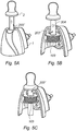
- FIGS 5A - 5C An alternative design to the evaporation device of Figures 4A and 4B is shown in Figures 5A - 5C .
- These figures show a design which uses a gel matrix wherein the reservoir 201' and fluid transport means 203' are integral with each other and wherein the gel may be supported by a lattice material (not shown) to impart mechanical strength thereto.
- a lattice material not shown
- Figures 6A - 6C show a further example of the evaporation device.
- the refill 2 comprises a wick 203 which lines the inside of the pod shaped refill 2.
- the wick is saturated with volatile fluid 202, and is evaporated by localised heat from a susceptor 204 also located in the wick 203 on one side of the pod.
- the refill 2 also comprises a cover 206 which can be perforated.
- the device 1 of the example shown in Figures 6A - 6C comprises tube like perforating elements 105 which are configured to pierce the cover 206 of the refill 2 during operation of the evaporation device.
- the induction coil 103 on the base element 1 is located to conform to the outer shape of the refill 2.
- a user places the refill 2 into the device 1 such that the susceptor 204 therein can interact with the induction coil 103 of the device 1.
- an alignment feature (not shown) could be provided on the refill 2 which locates with a corresponding feature on the device 1.
- the user then closes the lid of the device 1 to cause the perforating element 105 to pierce into the cover 206.
- the induction coil 103 then heats the susceptor 204 of the refill 2 as previously described, causing volatile fluid 202 in the wick 203 near the susceptor 204 to evaporate and flow out through the perforating elements 105.
- volatile fluid 202 which is near the susceptor 204 evaporates, volatile fluid 202 which is located further away from the susceptor 204 is drawn towards it by capillary action as previously described.
- the wick 203 could be designed in the form of a lattice as described above in relation to Figures 5A - 5C , or designed in any other shape that will support the gel.
- the perforating elements 105 may be configured to be made inaccessible when the device is not in use.
- FIG. 4A - 6C could be adapted to allow the accommodation of more than one refill 2.
- extra ports could be provided on the device 1 to allow the connection of additional refills 2.
- Each port on the device 1 could be provided with its own induction coil 103 such that the fluid 202 contained in each refill 2 could be heated independently of the fluid contained in the other refills 2.
- all the refills 2 could be selectively heated by a single induction coil 103 located on the device 1, using conventional time switching circuitry. Irrespective of the number of induction coils 103 or number of refills 2 used, the principle of operation would be the same as previously described.
- the material selected should be magnetic and should have a high hysteresis loss so that when it is repeatedly magnetised and demagnetised by an external magnetic field a relatively high proportion of the external field energy is converted into heat.
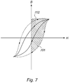
- the magnetic properties exhibited by such a magnetic material may be represented by a plot of flux density (B) against magnetic field strength (H) as shown in figure 7 .
- Materials having relatively low hysteresis losses are typified by the solid hysteresis loop which has a small area whilst materials having relatively high hysteresis losses are typified by the dotted hysteresis loop which has a high area.
- the proportion of the external magnetic field energy that is converted into heat by the susceptor for each magnetic cycle is proportional to the area of the hysteresis loop corresponding to the particular magnetic material. Accordingly magnetic materials having small area hysteresis loops generate less heat when subjected to a given alternating magnetic field and function poorly as susceptor materials. Conversely magnetic materials having large area hysteresis loops generate more heat when subjected to the same alternating magnetic field and function well as susceptor materials.
- the area of the hysteresis loop of a magnetic material is proportional to its coercivity so that a material having a high coercivity may be particularly suitable for use as a susceptor. Preferably such a material should have a coercivity greater than 50 amperes per meter and more preferably a coercivity in the range of 150 - 1500 ampere per meter.
- the chosen material should not have an excessively high coercivity in order that external alternating magnetic fields may readily bring about the necessary magnetic flux reversals in the material.
- Such materials are known as magnetically soft materials and are distinguished thereby from the very high coercivity magnetically hard materials which are typically used in permanent magnet applications.
Landscapes
- Life Sciences & Earth Sciences (AREA)
- Health & Medical Sciences (AREA)
- Pest Control & Pesticides (AREA)
- General Health & Medical Sciences (AREA)
- Engineering & Computer Science (AREA)
- Veterinary Medicine (AREA)
- Epidemiology (AREA)
- Public Health (AREA)
- Animal Behavior & Ethology (AREA)
- Physics & Mathematics (AREA)
- Insects & Arthropods (AREA)
- Environmental Sciences (AREA)
- Zoology (AREA)
- Wood Science & Technology (AREA)
- Toxicology (AREA)
- Electromagnetism (AREA)
- Sustainable Development (AREA)
- Sustainable Energy (AREA)
- Thermal Sciences (AREA)
- Mechanical Engineering (AREA)
- General Engineering & Computer Science (AREA)
- General Induction Heating (AREA)
- Disinfection, Sterilisation Or Deodorisation Of Air (AREA)
Claims (7)
- Einheit zum Verdampfen eines flüchtigen Fluids (202), wobei die Einheit eine Vorrichtung (1) und eine Nachfüllpackung (2) umfasst, die voneinander lösbar sind;
wobei die Vorrichtung (1) eine magnetische Induktionsspule (103) umfasst;
und wobei die Nachfüllpackung (2) ein Reservoir (201) für das flüchtige Fluid (202), ein Transportmittel (203) für flüchtiges Fluid, um das Fluid aus dem Reservoir (201) anzusaugen, und mindestens einen Suszeptor (204) umfasst, der zum Erwärmen des Transportmittels (203) für flüchtiges Fluid vorgesehen ist, wenn der Wechselstrom durch die Induktionsspule (103) hindurch geleitet wird;
wobei:das Transportmittel (203) für flüchtiges Fluid ein Docht ist; undder magnetische Suszeptor (204) mindestens teilweise in dem Transportmittel (203) für flüchtiges Fluid eingebettet ist. - Einheit nach Anspruch 1, wobei die Vorrichtung (1) ferner eine Steuereinheit zum Steuern des Betriebs der Induktionsspule (103) umfasst und wobei die Vorrichtung (1) ferner eine Rückkopplungsspule (104) umfasst, die konfiguriert ist, um mit einem von der Induktionsspule (103) erzeugten Magnetfeld wechselzuwirken, wobei die Steuereinheit konfiguriert ist, um eine Ausgabe von der Rückkopplungsspule (104) zu verarbeiten und anhand dieser Ausgabe einen oder mehrere Betriebsparameter der Induktionsspule (103) zu verändern.
- Nachfüllpackung zum Befestigen an einer Vorrichtung (1) zum Verdampfen eines flüchtigen Fluids (202), wobei die Nachfüllpackung (2) ein Reservoir (201) für das flüchtige Fluid (202) und ein Transportmittel (203) für flüchtiges Fluid zum Ansaugen des Fluids aus dem Reservoir (201) umfasst, wobei das Transportmittel (203) für flüchtiges Fluid auch mindestens einen Suszeptor (204) aufweist;
wobei:das Transportmittel (203) für flüchtiges Fluid ein Docht ist; undder magnetische Suszeptor (204) mindestens teilweise in dem Transportmittel (203) für flüchtiges Fluid eingebettet ist. - Nachfüllpackung nach Anspruch 3, wobei der Suszeptor (204) in direktem Kontakt mit dem Transportmittel (203) für flüchtiges Fluid bereitgestellt ist.
- Nachfüllpackung nach einem der Ansprüche 3-4, wobei das Transportmittel (203) für flüchtiges Fluid durch eine Kappe in der Nachfüllpackung (2) hervorsteht und sich in die Umgebung erstreckt, die die Nachfüllpackung (2) distal von dem Reservoir (201) umgibt, und der/die Suszeptor(en) (204) in Kontakt mit dem Transportmittel (203) für flüchtiges Fluid in einem distalen Abschnitt davon zwischen der Kappe und dem distalen Ende des Mittels bereitgestellt ist/sind.
- Verfahren zum Verdampfen eines flüchtigen Fluids (202), umfassend die Schritte des Platzierens einer Nachfüllpackung (2), die ein Reservoir (201) für das flüchtige Fluid (202), ein Transportmittel (203) für flüchtiges Fluid umfasst, um das Fluid aus dem Reservoir (201) in Richtung zu mindestens einem Suszeptor (204) in einer Vorrichtung (1) anzusaugen, die eine magnetische Induktionsspule (103) umfasst, die konfiguriert ist, dass sie mit einem dadurch hindurchgeleiteten Wechselstrom arbeitet, um ein Magnetfeld zu induzieren; Erzeugen eines Magnetfeldes durch die Induktionsspule (103) durch Hindurchleiten eines Wechselstroms;
wobei das Platzieren der Nachfüllpackung (2) in der Vorrichtung (1) derart ist, dass der mindestens eine Suszeptor (204) sich mindestens teilweise innerhalb des erzeugten Magnetfelds befindet;
und Verdampfen des flüchtigen Fluids (202), indem der mindestens eine Suszeptor (204) durch das sich verändernde Magnetfeld von der Induktionsspule (103) erwärmt wird, um das flüchtige Fluid (202) aus dem Transportmittel (203) für flüchtiges Fluid zu verdampfen; wobei:das Transportmittel (203) für flüchtiges Fluid ein Docht ist; undder magnetische Suszeptor (204) mindestens teilweise in dem Transportmittel (203) für flüchtiges Fluid eingebettet ist. - Verfahren nach Anspruch 6, wobei die Vorrichtung (1) ferner eine Steuereinheit und/oder eine Rückkopplungsspule (104) umfasst und das Verfahren ferner umfasst, dass die Steuereinheit den Betrieb der Induktionsspule (103) steuert, und das Verfahren ferner umfasst, dass die Steuereinheit eine Ausgabe der Rückkopplungsspule (104) verarbeitet, und anhand dieser Ausgabe einen oder mehrere Betriebsparameter der Induktionsspule (103) verändert, wobei die Rückkopplungsspule (104) konfiguriert ist, um bei Gebrauch ihre Ausgabe zu verändern, wenn eine Eigenschaft eines Suszeptors (204) von Nachfüllpackung (2) zu Nachfüllpackung (2) verändert wird, und das Verfahren ferner umfasst, dass die Steuereinheit konfiguriert ist, um die Veränderung der Ausgabe von der Rückkopplungsspule (104) zu interpretieren, um zu bestimmen, welche Art von Nachfüllpackung (2) sich innerhalb des Magnetfelds der Induktionsspule (103) befindet, und daraus automatisch eine Eigenschaft der Induktionsspule (103) dahingehend verändert, auf jede bestimmte Nachfüllpackung (2) das geeignete Erwärmungsregime anzuwenden.
Applications Claiming Priority (2)
| Application Number | Priority Date | Filing Date | Title |
|---|---|---|---|
| GB1214166.9A GB2504731B (en) | 2012-08-08 | 2012-08-08 | Device for evaporating a volatile fluid |
| PCT/GB2013/052120 WO2014023967A1 (en) | 2012-08-08 | 2013-08-08 | Device for evaporating a volatile fluid |
Publications (3)
| Publication Number | Publication Date |
|---|---|
| EP2882289A1 EP2882289A1 (de) | 2015-06-17 |
| EP2882289B1 true EP2882289B1 (de) | 2019-04-03 |
| EP2882289B8 EP2882289B8 (de) | 2019-05-22 |
Family
ID=46935101
Family Applications (1)
| Application Number | Title | Priority Date | Filing Date |
|---|---|---|---|
| EP13750116.9A Not-in-force EP2882289B8 (de) | 2012-08-08 | 2013-08-08 | Vorrichtung zum verdampfen einer flüchtigen flüssigkeit |
Country Status (9)
| Country | Link |
|---|---|
| US (1) | US10350321B2 (de) |
| EP (1) | EP2882289B8 (de) |
| AU (2) | AU2013301351B2 (de) |
| BR (1) | BR112015002663A2 (de) |
| CA (1) | CA2881139A1 (de) |
| GB (1) | GB2504731B (de) |
| RU (1) | RU2632976C2 (de) |
| WO (1) | WO2014023967A1 (de) |
| ZA (1) | ZA201500884B (de) |
Families Citing this family (33)
| Publication number | Priority date | Publication date | Assignee | Title |
|---|---|---|---|---|
| WO2013034459A1 (en) | 2011-09-06 | 2013-03-14 | British American Tobacco (Investments) Limited | Heating smokeable material |
| GB2504731B (en) * | 2012-08-08 | 2015-03-25 | Reckitt & Colman Overseas | Device for evaporating a volatile fluid |
| GB2516925B (en) * | 2013-08-07 | 2016-01-27 | Reckitt Benckiser Brands Ltd | Device for evaporating a volatile material |
| GB2516924B (en) | 2013-08-07 | 2016-01-20 | Reckitt Benckiser Brands Ltd | Device for evaporating a volatile fluid |
| WO2015131058A1 (en) * | 2014-02-28 | 2015-09-03 | Altria Client Services Inc. | Electronic vaping device and components thereof |
| HRP20182101T1 (hr) | 2014-05-12 | 2019-03-08 | Loto Labs, Inc. | Poboljšani uređaj za vaporizaciju |
| AU2015261847B2 (en) | 2014-05-21 | 2019-05-02 | Philip Morris Products S.A. | Aerosol-generating article with multi-material susceptor |
| TWI697289B (zh) | 2014-05-21 | 2020-07-01 | 瑞士商菲利浦莫里斯製品股份有限公司 | 氣溶膠形成製品、電熱氣溶膠產生裝置及系統、及操作該系統之方法 |
| TWI669072B (zh) | 2014-05-21 | 2019-08-21 | 瑞士商菲利浦莫里斯製品股份有限公司 | 電熱式霧劑產生系統及用於此系統中之匣筒 |
| JP2017525348A (ja) | 2014-07-24 | 2017-09-07 | アルトリア クライアント サービシーズ リミテッド ライアビリティ カンパニー | 電子たばこデバイスおよびその部品 |
| US9469521B2 (en) * | 2014-07-25 | 2016-10-18 | Alps South Europe S.R.O. | Induction heating device for shaving and cosmetic applications |
| BR112017022971B1 (pt) | 2015-05-13 | 2021-06-29 | Givaudan Sa | Método para a criação de uma fragrância de longa duração e impacto e dispositivo elétrico líquido de cuidados com o ar |
| GB201511349D0 (en) | 2015-06-29 | 2015-08-12 | Nicoventures Holdings Ltd | Electronic aerosol provision systems |
| GB201511358D0 (en) | 2015-06-29 | 2015-08-12 | Nicoventures Holdings Ltd | Electronic aerosol provision systems |
| GB201511361D0 (en) | 2015-06-29 | 2015-08-12 | Nicoventures Holdings Ltd | Electronic vapour provision system |
| GB201511359D0 (en) | 2015-06-29 | 2015-08-12 | Nicoventures Holdings Ltd | Electronic vapour provision system |
| US20170055584A1 (en) | 2015-08-31 | 2017-03-02 | British American Tobacco (Investments) Limited | Article for use with apparatus for heating smokable material |
| US11924930B2 (en) | 2015-08-31 | 2024-03-05 | Nicoventures Trading Limited | Article for use with apparatus for heating smokable material |
| US20170055574A1 (en) | 2015-08-31 | 2017-03-02 | British American Tobacco (Investments) Limited | Cartridge for use with apparatus for heating smokable material |
| TW201714534A (zh) * | 2015-10-22 | 2017-05-01 | 菲利浦莫里斯製品股份有限公司 | 氣溶膠輸送系統及操作該氣溶膠輸送系統的方法 |
| US20180317554A1 (en) | 2015-10-30 | 2018-11-08 | British American Tobacco (Investments) Limited | Article for use with apparatus for heating smokable material |
| US20170119051A1 (en) | 2015-10-30 | 2017-05-04 | British American Tobacco (Investments) Limited | Article for Use with Apparatus for Heating Smokable Material |
| US20170119050A1 (en) | 2015-10-30 | 2017-05-04 | British American Tobacco (Investments) Limited | Article for Use with Apparatus for Heating Smokable Material |
| US20170119049A1 (en) | 2015-10-30 | 2017-05-04 | British American Tobacco (Investments) Limited | Article for Use with Apparatus for Heating Smokable Material |
| US20170119046A1 (en) | 2015-10-30 | 2017-05-04 | British American Tobacco (Investments) Limited | Apparatus for Heating Smokable Material |
| KR102468749B1 (ko) | 2016-06-29 | 2022-11-17 | 니코벤처스 트레이딩 리미티드 | 흡연가능 물질을 가열하기 위한 장치 |
| US12478096B2 (en) | 2016-06-29 | 2025-11-25 | Nicoventures Trading Limited | Apparatus for heating smokable material |
| EP3478104B1 (de) | 2016-06-29 | 2023-03-22 | Nicoventures Trading Limited | Vorrichtung zur erwärmung von rauchbarem material |
| GB201705206D0 (en) | 2017-03-31 | 2017-05-17 | British American Tobacco Investments Ltd | Apparatus for a resonance circuit |
| CA3075657C (en) | 2017-09-15 | 2023-10-10 | British American Tobacco (Investments) Limited | Apparatus for heating smokable material |
| GB2572450B (en) * | 2018-03-30 | 2020-03-18 | Bhatia Anand | Liquid Vaporiser Assembly |
| GB201814202D0 (en) * | 2018-08-31 | 2018-10-17 | Nicoventures Trading Ltd | A resonant circuit for an aerosol generating system |
| CN111330059A (zh) * | 2020-03-31 | 2020-06-26 | 惠州市顺鑫宏电子科技有限公司 | 一种usb接口低压香薰加热器 |
Family Cites Families (29)
| Publication number | Priority date | Publication date | Assignee | Title |
|---|---|---|---|---|
| US1975436A (en) * | 1929-11-08 | 1934-10-02 | Ugine Infra | Method of heating by induction and furnace therefor |
| US4256945A (en) * | 1979-08-31 | 1981-03-17 | Iris Associates | Alternating current electrically resistive heating element having intrinsic temperature control |
| JPS58225595A (ja) * | 1982-06-24 | 1983-12-27 | 三洋電機株式会社 | 誘導加熱調理器 |
| US5128504A (en) * | 1990-04-20 | 1992-07-07 | Metcal, Inc. | Removable heating article for use in alternating magnetic field |
| SU1796269A1 (en) * | 1990-04-23 | 1993-02-23 | Mo Aviatsionnyj I Im S Ordzhon | Method and device for fluid spraying |
| US5613505A (en) * | 1992-09-11 | 1997-03-25 | Philip Morris Incorporated | Inductive heating systems for smoking articles |
| GB9600211D0 (en) * | 1996-01-05 | 1996-03-06 | Jem Smoke Machine Company Limi | Improvements in or relating to a vaporiser |
| US6792199B2 (en) * | 2000-02-25 | 2004-09-14 | The Dial Corporation | Variable temperature vaporizer |
| CA2337738C (en) * | 2000-02-25 | 2008-05-13 | The Dial Corporation | Variable temperature vaporizer |
| US7193193B2 (en) * | 2002-03-01 | 2007-03-20 | Board Of Control Of Michigan Technological University | Magnetic annealing of ferromagnetic thin films using induction heating |
| GB0410777D0 (en) * | 2004-05-14 | 2004-06-16 | Givauden Sa | Apparatus |
| WO2007101298A1 (en) * | 2006-03-09 | 2007-09-13 | Resmed Ltd | Induction heating system and method for humidifier |
| JP2008020096A (ja) * | 2006-07-11 | 2008-01-31 | Kobe Steel Ltd | 誘導加熱式純水加熱装置および純水加熱方法 |
| US20080226269A1 (en) * | 2007-03-16 | 2008-09-18 | Innovative Instruments, Inc. | Vapor generator |
| WO2008148154A1 (en) * | 2007-06-05 | 2008-12-11 | Resmed Ltd | Electrical heater with particular application to humidification and fluid warming |
| KR101197340B1 (ko) * | 2008-04-11 | 2012-11-05 | 도시바 미쓰비시덴키 산교시스템 가부시키가이샤 | 균열 장치 및 유기막 성막 장치 |
| US8897628B2 (en) * | 2009-07-27 | 2014-11-25 | Gregory D. Conley | Electronic vaporizer |
| EP2509081A1 (de) * | 2011-04-07 | 2012-10-10 | Höganäs AB | Neue Zusammensetzung und Verfahren |
| EP2744525A1 (de) * | 2011-08-15 | 2014-06-25 | Porex Corporation | Leitender verbunddocht sowie verfahren zu seiner herstellung und verwendung |
| CN102384577B (zh) * | 2011-11-01 | 2014-07-16 | 吴荣华 | 液用三相工频电磁双重感应加热装置 |
| GB2504730B (en) * | 2012-08-08 | 2015-01-14 | Reckitt & Colman Overseas | Device for evaporating a volatile fluid |
| GB2504731B (en) * | 2012-08-08 | 2015-03-25 | Reckitt & Colman Overseas | Device for evaporating a volatile fluid |
| GB2504732B (en) * | 2012-08-08 | 2015-01-14 | Reckitt & Colman Overseas | Device for evaporating a volatile material |
| GB2504733B (en) * | 2012-08-08 | 2015-05-20 | Reckitt & Colman Overseas | Device for evaporating a volatile material |
| GB2516925B (en) * | 2013-08-07 | 2016-01-27 | Reckitt Benckiser Brands Ltd | Device for evaporating a volatile material |
| GB2516924B (en) * | 2013-08-07 | 2016-01-20 | Reckitt Benckiser Brands Ltd | Device for evaporating a volatile fluid |
| TWI697289B (zh) * | 2014-05-21 | 2020-07-01 | 瑞士商菲利浦莫里斯製品股份有限公司 | 氣溶膠形成製品、電熱氣溶膠產生裝置及系統、及操作該系統之方法 |
| TWI669072B (zh) * | 2014-05-21 | 2019-08-21 | 瑞士商菲利浦莫里斯製品股份有限公司 | 電熱式霧劑產生系統及用於此系統中之匣筒 |
| TWI660685B (zh) * | 2014-05-21 | 2019-06-01 | 瑞士商菲利浦莫里斯製品股份有限公司 | 電熱式氣溶膠產生系統及用於此系統中之匣筒 |
-
2012
- 2012-08-08 GB GB1214166.9A patent/GB2504731B/en not_active Expired - Fee Related
-
2013
- 2013-08-08 RU RU2015107837A patent/RU2632976C2/ru not_active IP Right Cessation
- 2013-08-08 AU AU2013301351A patent/AU2013301351B2/en not_active Ceased
- 2013-08-08 US US14/420,225 patent/US10350321B2/en not_active Expired - Fee Related
- 2013-08-08 CA CA2881139A patent/CA2881139A1/en not_active Abandoned
- 2013-08-08 EP EP13750116.9A patent/EP2882289B8/de not_active Not-in-force
- 2013-08-08 WO PCT/GB2013/052120 patent/WO2014023967A1/en not_active Ceased
- 2013-08-08 BR BR112015002663A patent/BR112015002663A2/pt not_active Application Discontinuation
-
2015
- 2015-02-06 ZA ZA2015/00884A patent/ZA201500884B/en unknown
-
2017
- 2017-06-06 AU AU2017203808A patent/AU2017203808B2/en not_active Expired - Fee Related
Non-Patent Citations (1)
| Title |
|---|
| None * |
Also Published As
| Publication number | Publication date |
|---|---|
| BR112015002663A2 (pt) | 2018-02-14 |
| GB2504731B (en) | 2015-03-25 |
| CA2881139A1 (en) | 2014-02-13 |
| GB201214166D0 (en) | 2012-09-19 |
| US10350321B2 (en) | 2019-07-16 |
| GB2504731A (en) | 2014-02-12 |
| AU2017203808B2 (en) | 2019-07-11 |
| WO2014023967A1 (en) | 2014-02-13 |
| AU2013301351A1 (en) | 2015-02-26 |
| AU2017203808A1 (en) | 2017-06-22 |
| AU2013301351B2 (en) | 2017-06-29 |
| RU2632976C2 (ru) | 2017-10-11 |
| EP2882289B8 (de) | 2019-05-22 |
| US20150157756A1 (en) | 2015-06-11 |
| EP2882289A1 (de) | 2015-06-17 |
| RU2015107837A (ru) | 2016-09-27 |
| ZA201500884B (en) | 2017-08-30 |
Similar Documents
| Publication | Publication Date | Title |
|---|---|---|
| US10350321B2 (en) | Device for evaporating a volatile fluid | |
| US9877359B2 (en) | Device for evaporating a volatile fluid | |
| US10293069B2 (en) | Device for evaporating a volatile fluid | |
| EP2882288B1 (de) | Vorrichtung zum verdampfen eines flüchtigen produkts | |
| EP2882287B1 (de) | Vorrichtung zum verdampfen eines flüchtigen produkts |
Legal Events
| Date | Code | Title | Description |
|---|---|---|---|
| PUAI | Public reference made under article 153(3) epc to a published international application that has entered the european phase |
Free format text: ORIGINAL CODE: 0009012 |
|
| 17P | Request for examination filed |
Effective date: 20150302 |
|
| AK | Designated contracting states |
Kind code of ref document: A1 Designated state(s): AL AT BE BG CH CY CZ DE DK EE ES FI FR GB GR HR HU IE IS IT LI LT LU LV MC MK MT NL NO PL PT RO RS SE SI SK SM TR |
|
| AX | Request for extension of the european patent |
Extension state: BA ME |
|
| DAX | Request for extension of the european patent (deleted) | ||
| STAA | Information on the status of an ep patent application or granted ep patent |
Free format text: STATUS: EXAMINATION IS IN PROGRESS |
|
| 17Q | First examination report despatched |
Effective date: 20180709 |
|
| REG | Reference to a national code |
Ref country code: DE Ref legal event code: R079 Ref document number: 602013053309 Country of ref document: DE Free format text: PREVIOUS MAIN CLASS: A01M0001200000 Ipc: F22B0001280000 |
|
| GRAP | Despatch of communication of intention to grant a patent |
Free format text: ORIGINAL CODE: EPIDOSNIGR1 |
|
| STAA | Information on the status of an ep patent application or granted ep patent |
Free format text: STATUS: GRANT OF PATENT IS INTENDED |
|
| RIC1 | Information provided on ipc code assigned before grant |
Ipc: F22B 1/28 20060101AFI20181108BHEP Ipc: A01M 1/20 20060101ALI20181108BHEP Ipc: A61L 9/03 20060101ALI20181108BHEP |
|
| INTG | Intention to grant announced |
Effective date: 20181123 |
|
| GRAS | Grant fee paid |
Free format text: ORIGINAL CODE: EPIDOSNIGR3 |
|
| GRAA | (expected) grant |
Free format text: ORIGINAL CODE: 0009210 |
|
| STAA | Information on the status of an ep patent application or granted ep patent |
Free format text: STATUS: THE PATENT HAS BEEN GRANTED |
|
| AK | Designated contracting states |
Kind code of ref document: B1 Designated state(s): AL AT BE BG CH CY CZ DE DK EE ES FI FR GB GR HR HU IE IS IT LI LT LU LV MC MK MT NL NO PL PT RO RS SE SI SK SM TR |
|
| REG | Reference to a national code |
Ref country code: GB Ref legal event code: FG4D |
|
| REG | Reference to a national code |
Ref country code: CH Ref legal event code: EP Ref country code: AT Ref legal event code: REF Ref document number: 1116193 Country of ref document: AT Kind code of ref document: T Effective date: 20190415 |
|
| RBV | Designated contracting states (corrected) |
Designated state(s): AL AT BE BG CH CY CZ DE DK EE ES FI FR GR HR HU IE IS IT LI LT LU LV MC MK MT NL NO PL PT RO RS SE SI SK SM TR |
|
| REG | Reference to a national code |
Ref country code: DE Ref legal event code: R096 Ref document number: 602013053309 Country of ref document: DE |
|
| REG | Reference to a national code |
Ref country code: CH Ref legal event code: PK Free format text: BERICHTIGUNG B8 |
|
| REG | Reference to a national code |
Ref country code: IE Ref legal event code: FG4D |
|
| RAP2 | Party data changed (patent owner data changed or rights of a patent transferred) |
Owner name: RECKITT & COLMAN (OVERSEAS) HYGIENE HOME LIMITED |
|
| REG | Reference to a national code |
Ref country code: NL Ref legal event code: MP Effective date: 20190403 |
|
| REG | Reference to a national code |
Ref country code: LT Ref legal event code: MG4D |
|
| REG | Reference to a national code |
Ref country code: AT Ref legal event code: MK05 Ref document number: 1116193 Country of ref document: AT Kind code of ref document: T Effective date: 20190403 |
|
| PG25 | Lapsed in a contracting state [announced via postgrant information from national office to epo] |
Ref country code: NL Free format text: LAPSE BECAUSE OF FAILURE TO SUBMIT A TRANSLATION OF THE DESCRIPTION OR TO PAY THE FEE WITHIN THE PRESCRIBED TIME-LIMIT Effective date: 20190403 |
|
| PG25 | Lapsed in a contracting state [announced via postgrant information from national office to epo] |
Ref country code: HR Free format text: LAPSE BECAUSE OF FAILURE TO SUBMIT A TRANSLATION OF THE DESCRIPTION OR TO PAY THE FEE WITHIN THE PRESCRIBED TIME-LIMIT Effective date: 20190403 Ref country code: SE Free format text: LAPSE BECAUSE OF FAILURE TO SUBMIT A TRANSLATION OF THE DESCRIPTION OR TO PAY THE FEE WITHIN THE PRESCRIBED TIME-LIMIT Effective date: 20190403 Ref country code: ES Free format text: LAPSE BECAUSE OF FAILURE TO SUBMIT A TRANSLATION OF THE DESCRIPTION OR TO PAY THE FEE WITHIN THE PRESCRIBED TIME-LIMIT Effective date: 20190403 Ref country code: LT Free format text: LAPSE BECAUSE OF FAILURE TO SUBMIT A TRANSLATION OF THE DESCRIPTION OR TO PAY THE FEE WITHIN THE PRESCRIBED TIME-LIMIT Effective date: 20190403 Ref country code: CZ Free format text: LAPSE BECAUSE OF FAILURE TO SUBMIT A TRANSLATION OF THE DESCRIPTION OR TO PAY THE FEE WITHIN THE PRESCRIBED TIME-LIMIT Effective date: 20190403 Ref country code: NO Free format text: LAPSE BECAUSE OF FAILURE TO SUBMIT A TRANSLATION OF THE DESCRIPTION OR TO PAY THE FEE WITHIN THE PRESCRIBED TIME-LIMIT Effective date: 20190703 Ref country code: PT Free format text: LAPSE BECAUSE OF FAILURE TO SUBMIT A TRANSLATION OF THE DESCRIPTION OR TO PAY THE FEE WITHIN THE PRESCRIBED TIME-LIMIT Effective date: 20190803 Ref country code: FI Free format text: LAPSE BECAUSE OF FAILURE TO SUBMIT A TRANSLATION OF THE DESCRIPTION OR TO PAY THE FEE WITHIN THE PRESCRIBED TIME-LIMIT Effective date: 20190403 Ref country code: AL Free format text: LAPSE BECAUSE OF FAILURE TO SUBMIT A TRANSLATION OF THE DESCRIPTION OR TO PAY THE FEE WITHIN THE PRESCRIBED TIME-LIMIT Effective date: 20190403 |
|
| PGFP | Annual fee paid to national office [announced via postgrant information from national office to epo] |
Ref country code: DE Payment date: 20190723 Year of fee payment: 7 Ref country code: FR Payment date: 20190830 Year of fee payment: 7 |
|
| PG25 | Lapsed in a contracting state [announced via postgrant information from national office to epo] |
Ref country code: GR Free format text: LAPSE BECAUSE OF FAILURE TO SUBMIT A TRANSLATION OF THE DESCRIPTION OR TO PAY THE FEE WITHIN THE PRESCRIBED TIME-LIMIT Effective date: 20190704 Ref country code: BG Free format text: LAPSE BECAUSE OF FAILURE TO SUBMIT A TRANSLATION OF THE DESCRIPTION OR TO PAY THE FEE WITHIN THE PRESCRIBED TIME-LIMIT Effective date: 20190703 Ref country code: PL Free format text: LAPSE BECAUSE OF FAILURE TO SUBMIT A TRANSLATION OF THE DESCRIPTION OR TO PAY THE FEE WITHIN THE PRESCRIBED TIME-LIMIT Effective date: 20190403 Ref country code: RS Free format text: LAPSE BECAUSE OF FAILURE TO SUBMIT A TRANSLATION OF THE DESCRIPTION OR TO PAY THE FEE WITHIN THE PRESCRIBED TIME-LIMIT Effective date: 20190403 Ref country code: LV Free format text: LAPSE BECAUSE OF FAILURE TO SUBMIT A TRANSLATION OF THE DESCRIPTION OR TO PAY THE FEE WITHIN THE PRESCRIBED TIME-LIMIT Effective date: 20190403 |
|
| PG25 | Lapsed in a contracting state [announced via postgrant information from national office to epo] |
Ref country code: IS Free format text: LAPSE BECAUSE OF FAILURE TO SUBMIT A TRANSLATION OF THE DESCRIPTION OR TO PAY THE FEE WITHIN THE PRESCRIBED TIME-LIMIT Effective date: 20190803 Ref country code: AT Free format text: LAPSE BECAUSE OF FAILURE TO SUBMIT A TRANSLATION OF THE DESCRIPTION OR TO PAY THE FEE WITHIN THE PRESCRIBED TIME-LIMIT Effective date: 20190403 |
|
| REG | Reference to a national code |
Ref country code: DE Ref legal event code: R097 Ref document number: 602013053309 Country of ref document: DE |
|
| PG25 | Lapsed in a contracting state [announced via postgrant information from national office to epo] |
Ref country code: EE Free format text: LAPSE BECAUSE OF FAILURE TO SUBMIT A TRANSLATION OF THE DESCRIPTION OR TO PAY THE FEE WITHIN THE PRESCRIBED TIME-LIMIT Effective date: 20190403 Ref country code: DK Free format text: LAPSE BECAUSE OF FAILURE TO SUBMIT A TRANSLATION OF THE DESCRIPTION OR TO PAY THE FEE WITHIN THE PRESCRIBED TIME-LIMIT Effective date: 20190403 Ref country code: SK Free format text: LAPSE BECAUSE OF FAILURE TO SUBMIT A TRANSLATION OF THE DESCRIPTION OR TO PAY THE FEE WITHIN THE PRESCRIBED TIME-LIMIT Effective date: 20190403 Ref country code: RO Free format text: LAPSE BECAUSE OF FAILURE TO SUBMIT A TRANSLATION OF THE DESCRIPTION OR TO PAY THE FEE WITHIN THE PRESCRIBED TIME-LIMIT Effective date: 20190403 |
|
| PLBE | No opposition filed within time limit |
Free format text: ORIGINAL CODE: 0009261 |
|
| STAA | Information on the status of an ep patent application or granted ep patent |
Free format text: STATUS: NO OPPOSITION FILED WITHIN TIME LIMIT |
|
| PG25 | Lapsed in a contracting state [announced via postgrant information from national office to epo] |
Ref country code: IT Free format text: LAPSE BECAUSE OF FAILURE TO SUBMIT A TRANSLATION OF THE DESCRIPTION OR TO PAY THE FEE WITHIN THE PRESCRIBED TIME-LIMIT Effective date: 20190403 Ref country code: SM Free format text: LAPSE BECAUSE OF FAILURE TO SUBMIT A TRANSLATION OF THE DESCRIPTION OR TO PAY THE FEE WITHIN THE PRESCRIBED TIME-LIMIT Effective date: 20190403 |
|
| 26N | No opposition filed |
Effective date: 20200106 |
|
| PG25 | Lapsed in a contracting state [announced via postgrant information from national office to epo] |
Ref country code: TR Free format text: LAPSE BECAUSE OF FAILURE TO SUBMIT A TRANSLATION OF THE DESCRIPTION OR TO PAY THE FEE WITHIN THE PRESCRIBED TIME-LIMIT Effective date: 20190403 |
|
| PG25 | Lapsed in a contracting state [announced via postgrant information from national office to epo] |
Ref country code: LU Free format text: LAPSE BECAUSE OF NON-PAYMENT OF DUE FEES Effective date: 20190808 Ref country code: SI Free format text: LAPSE BECAUSE OF FAILURE TO SUBMIT A TRANSLATION OF THE DESCRIPTION OR TO PAY THE FEE WITHIN THE PRESCRIBED TIME-LIMIT Effective date: 20190403 Ref country code: LI Free format text: LAPSE BECAUSE OF NON-PAYMENT OF DUE FEES Effective date: 20190831 Ref country code: CH Free format text: LAPSE BECAUSE OF NON-PAYMENT OF DUE FEES Effective date: 20190831 Ref country code: MC Free format text: LAPSE BECAUSE OF FAILURE TO SUBMIT A TRANSLATION OF THE DESCRIPTION OR TO PAY THE FEE WITHIN THE PRESCRIBED TIME-LIMIT Effective date: 20190403 |
|
| REG | Reference to a national code |
Ref country code: BE Ref legal event code: MM Effective date: 20190831 |
|
| PG25 | Lapsed in a contracting state [announced via postgrant information from national office to epo] |
Ref country code: IE Free format text: LAPSE BECAUSE OF NON-PAYMENT OF DUE FEES Effective date: 20190808 |
|
| PG25 | Lapsed in a contracting state [announced via postgrant information from national office to epo] |
Ref country code: BE Free format text: LAPSE BECAUSE OF NON-PAYMENT OF DUE FEES Effective date: 20190831 |
|
| REG | Reference to a national code |
Ref country code: DE Ref legal event code: R119 Ref document number: 602013053309 Country of ref document: DE |
|
| PG25 | Lapsed in a contracting state [announced via postgrant information from national office to epo] |
Ref country code: CY Free format text: LAPSE BECAUSE OF FAILURE TO SUBMIT A TRANSLATION OF THE DESCRIPTION OR TO PAY THE FEE WITHIN THE PRESCRIBED TIME-LIMIT Effective date: 20190403 |
|
| PG25 | Lapsed in a contracting state [announced via postgrant information from national office to epo] |
Ref country code: DE Free format text: LAPSE BECAUSE OF NON-PAYMENT OF DUE FEES Effective date: 20210302 Ref country code: MT Free format text: LAPSE BECAUSE OF FAILURE TO SUBMIT A TRANSLATION OF THE DESCRIPTION OR TO PAY THE FEE WITHIN THE PRESCRIBED TIME-LIMIT Effective date: 20190403 Ref country code: HU Free format text: LAPSE BECAUSE OF FAILURE TO SUBMIT A TRANSLATION OF THE DESCRIPTION OR TO PAY THE FEE WITHIN THE PRESCRIBED TIME-LIMIT; INVALID AB INITIO Effective date: 20130808 Ref country code: FR Free format text: LAPSE BECAUSE OF NON-PAYMENT OF DUE FEES Effective date: 20200831 |
|
| PG25 | Lapsed in a contracting state [announced via postgrant information from national office to epo] |
Ref country code: MK Free format text: LAPSE BECAUSE OF FAILURE TO SUBMIT A TRANSLATION OF THE DESCRIPTION OR TO PAY THE FEE WITHIN THE PRESCRIBED TIME-LIMIT Effective date: 20190403 |