EP2881671B1 - Hotplate device - Google Patents
Hotplate device Download PDFInfo
- Publication number
- EP2881671B1 EP2881671B1 EP14195005.5A EP14195005A EP2881671B1 EP 2881671 B1 EP2881671 B1 EP 2881671B1 EP 14195005 A EP14195005 A EP 14195005A EP 2881671 B1 EP2881671 B1 EP 2881671B1
- Authority
- EP
- European Patent Office
- Prior art keywords
- housing
- hotplate
- unit
- assembled state
- housing component
- Prior art date
- Legal status (The legal status is an assumption and is not a legal conclusion. Google has not performed a legal analysis and makes no representation as to the accuracy of the status listed.)
- Active
Links
- 238000000034 method Methods 0.000 claims description 10
- 230000006698 induction Effects 0.000 claims description 8
- 238000010411 cooking Methods 0.000 description 19
- 238000003860 storage Methods 0.000 description 12
- 238000010438 heat treatment Methods 0.000 description 11
- 238000004519 manufacturing process Methods 0.000 description 5
- 230000008569 process Effects 0.000 description 4
- 238000013461 design Methods 0.000 description 3
- 239000004033 plastic Substances 0.000 description 3
- 229920003023 plastic Polymers 0.000 description 3
- 238000013459 approach Methods 0.000 description 2
- 239000000919 ceramic Substances 0.000 description 2
- 239000013013 elastic material Substances 0.000 description 2
- 239000012777 electrically insulating material Substances 0.000 description 2
- 238000009434 installation Methods 0.000 description 2
- 239000000463 material Substances 0.000 description 2
- 235000001674 Agaricus brunnescens Nutrition 0.000 description 1
- 239000004953 Aliphatic polyamide Substances 0.000 description 1
- 229920002292 Nylon 6 Polymers 0.000 description 1
- 229920002302 Nylon 6,6 Polymers 0.000 description 1
- 239000004952 Polyamide Substances 0.000 description 1
- 239000004743 Polypropylene Substances 0.000 description 1
- 238000004026 adhesive bonding Methods 0.000 description 1
- 229920003231 aliphatic polyamide Polymers 0.000 description 1
- 229910052782 aluminium Inorganic materials 0.000 description 1
- XAGFODPZIPBFFR-UHFFFAOYSA-N aluminium Chemical compound [Al] XAGFODPZIPBFFR-UHFFFAOYSA-N 0.000 description 1
- 238000005266 casting Methods 0.000 description 1
- 230000001419 dependent effect Effects 0.000 description 1
- 230000005684 electric field Effects 0.000 description 1
- 230000005670 electromagnetic radiation Effects 0.000 description 1
- 235000013305 food Nutrition 0.000 description 1
- 238000001746 injection moulding Methods 0.000 description 1
- 238000003780 insertion Methods 0.000 description 1
- 230000037431 insertion Effects 0.000 description 1
- 230000003993 interaction Effects 0.000 description 1
- 229910052751 metal Inorganic materials 0.000 description 1
- 239000002184 metal Substances 0.000 description 1
- 238000012986 modification Methods 0.000 description 1
- 230000004048 modification Effects 0.000 description 1
- 229920002647 polyamide Polymers 0.000 description 1
- 229920000515 polycarbonate Polymers 0.000 description 1
- 239000004417 polycarbonate Substances 0.000 description 1
- 229920000379 polypropylene carbonate Polymers 0.000 description 1
- 230000005855 radiation Effects 0.000 description 1
- 238000003466 welding Methods 0.000 description 1
Images


Classifications
-
- F—MECHANICAL ENGINEERING; LIGHTING; HEATING; WEAPONS; BLASTING
- F24—HEATING; RANGES; VENTILATING
- F24C—DOMESTIC STOVES OR RANGES ; DETAILS OF DOMESTIC STOVES OR RANGES, OF GENERAL APPLICATION
- F24C7/00—Stoves or ranges heated by electric energy
- F24C7/08—Arrangement or mounting of control or safety devices
- F24C7/082—Arrangement or mounting of control or safety devices on ranges, e.g. control panels, illumination
- F24C7/083—Arrangement or mounting of control or safety devices on ranges, e.g. control panels, illumination on tops, hot plates
-
- F—MECHANICAL ENGINEERING; LIGHTING; HEATING; WEAPONS; BLASTING
- F24—HEATING; RANGES; VENTILATING
- F24C—DOMESTIC STOVES OR RANGES ; DETAILS OF DOMESTIC STOVES OR RANGES, OF GENERAL APPLICATION
- F24C7/00—Stoves or ranges heated by electric energy
- F24C7/08—Arrangement or mounting of control or safety devices
- F24C7/082—Arrangement or mounting of control or safety devices on ranges, e.g. control panels, illumination
- F24C7/086—Arrangement or mounting of control or safety devices on ranges, e.g. control panels, illumination touch control
-
- F—MECHANICAL ENGINEERING; LIGHTING; HEATING; WEAPONS; BLASTING
- F24—HEATING; RANGES; VENTILATING
- F24C—DOMESTIC STOVES OR RANGES ; DETAILS OF DOMESTIC STOVES OR RANGES, OF GENERAL APPLICATION
- F24C15/00—Details
-
- F—MECHANICAL ENGINEERING; LIGHTING; HEATING; WEAPONS; BLASTING
- F24—HEATING; RANGES; VENTILATING
- F24C—DOMESTIC STOVES OR RANGES ; DETAILS OF DOMESTIC STOVES OR RANGES, OF GENERAL APPLICATION
- F24C15/00—Details
- F24C15/10—Tops, e.g. hot plates; Rings
- F24C15/102—Tops, e.g. hot plates; Rings electrically heated
Definitions
- a hob apparatus comprising an outer casing formed by a cooking plate and a housing unit.
- the housing unit is formed as a one-piece component and has a recess through which engages in an assembled state, an engagement member of the carrier unit.
- the recess is disposed in a side wall of the housing unit and limited in a plane formed by the side wall from all sides by the side wall.
- the carrier unit is thereby aligned in a direction oriented perpendicular to the cooking plate plate by a spring which is supported on a bottom of the housing unit.
- An arrangement of the carrier unit in a direction parallel to the hob plate direction is defined by an extension of the engagement member and its play in the recess of the housing unit.
- the object of the invention is in particular to provide a generic device with improved properties in terms of assembly and manufacturing costs.
- the object is achieved by the features of claim 1, while advantageous embodiments and modifications of the invention can be taken from the dependent claims.
- a hob device in particular an induction hob device, proposed with a cooktop plate, with a housing unit which forms in an assembled state together with the cooktop an outer housing, in particular a cooktop outer housing, and which has at least one housing component and at least one side member provided thereto to be connected to the at least one housing component and with the cooktop panel, and with at least one support unit which is mounted in the mounted state on the housing unit and in an installed position for holding at least one touch control unit, wherein the at least one housing component and the at least one side member is provided together to fix the at least one carrier unit at least in a direction parallel to a main extension plane of the cooking field plate, and with at least one in the assembled state with the at least one door Actuator operatively connected engagement element, which is intended to at least partially reach through the housing member, characterized in that the at least one support unit and the at least one engagement element are integrally formed.
- a “cooking field device” should be understood to mean, in particular, at least one part, in particular a subassembly, of a hob, in particular an induction hob become.
- the hob device may also comprise the entire hob, in particular the entire induction hob.
- a “cooktop panel” is to be understood in particular an element which is intended to carry in a mounting position on the heating area set up cooking utensils and / or on-hook food.
- the hob plate and the housing unit together define at least one, in particular designed as a cavity, storage space for storage of components, for example at least one heating element, at least one control unit and / or at least one hob electronics, in particular the housing unit and advantageously the at least one housing component at least one Floor of storage room trains.
- a "housing component” is to be understood in particular as a component which, at least in an installed position, forms at least part of a lower and / or lateral wall, in particular at least part of a floor and / or a wall, of the housing unit.
- the at least one housing component in the installed position particularly forms a housing bottom and advantageously at least one part, in particular at least a majority of a housing wall, wherein the at least one housing component advantageously at least substantially has a shape of a cuboid opened on one side, in particular a top side.
- a "side component” is to be understood in particular as a component which forms at least a part of a lateral wall of the housing unit and in particular of the outer housing at least in an installed position, a normal vector of a main extension plane of the side component preferably being at least substantially parallel to the hob plate in the assembled state is.
- At least one subregion of the at least one side component forms at least one lateral wall of a cooktop frame, which at least partially surrounds the cooktop panel in the assembled state, in particular surrounds it.
- the at least one side component and the at least one housing component are formed separately from one another.
- the at least one side component is intended to be "connected" to the at least one housing component and to the cooktop panel, it should be understood in particular that in the assembled state the at least one side component and the at least one housing component are in particular detachable, advantageous non-positively and / or positively, are fixed to each other and that in the assembled state, the at least one side member and the cooktop plate in particular fixed, preferably cohesively, are attached to each other.
- Carrier unit is to be understood in particular a unit which is intended to receive in the installed position at least a major part of a weight of the at least one touch-control unit and / or to keep the at least one touch-control unit in at least one fixed position.
- the at least one carrier unit is provided, in particular, to divert the recorded weight force of the at least one touch-control unit to at least one further unit, in particular to the housing unit and / or to at least one room divider element.
- the at least one carrier unit made of an electrically insulating material, for example at least partially made of plastic and / or ceramic.
- a “touch-control unit” is to be understood in particular as a unit with at least one touch-sensitive and / or proximity-sensitive sensor, which is intended in particular for touching and / or approaching by an operator, in particular an approach of a body part, for example a finger an operator, in particular within a distance of a maximum of 10 mm, in particular a maximum of 3 mm, advantageously to detect a maximum of 1 mm, preferably a maximum of 0.5 mm.
- the at least one sensor preferably detects an approach independently of a direct contact and / or pressure, in particular through a contact surface element, in particular through the cooktop plate.
- the at least one carrier unit is provided in an installed position for "holding" at least one touch-control unit, it should be understood in particular that the at least one touch-control unit is arranged in the installed position above the at least one carrier unit.
- the at least one housing component and the at least one side component are provided "together” to fix the at least one carrier unit at least in a direction parallel to a main extension plane of the cooking field plate, should be understood in particular that the at least one housing component and the at least one side member are provided to fix by interaction the at least one carrier unit at least in the direction parallel to the main extension plane of the cooking plate plate direction.
- the at least one housing component and the at least one side component in the assembled state contact at least one element which is in operative connection with the at least one carrier unit.
- the at least one carrier unit at least in one of a main extension plane of the cooking field plate parallel direction to "fix"
- the at least one carrier unit in the mounted state by a maximum of 10 mm, in particular by a maximum of 5 mm, advantageously by a maximum of 2 mm and preferably immovable relative to the at least one housing component and to arrange the at least one side member.
- a “main plane of extension” of an object should in particular be understood to mean a plane which is parallel to a largest side surface of a smallest geometric cuboid which just completely surrounds the object, and in particular runs through the center of the cuboid.
- "intended” is intended to be understood in particular specially designed and / or equipped.
- the fact that an object is intended for a specific function should in particular mean that the object fulfills and / or executes this specific function in at least one application and / or operating state.
- an accurate and / or positionally accurate arrangement of components can be achieved, and the carrier unit, in particular the touch-control unit, can be arranged in a positionally accurate manner with a small number of components.
- the carrier unit in particular the touch-control unit
- an exact match of positions of sensors of the touch control unit relative to positions of markings on the cooking surface forming a cooking surface plate, which in particular an operator indicate a position of sensors, can be achieved.
- a simple and / or quick assembly process can be achieved.
- production problems for example due to inaccurate alignment of components, can be avoided.
- the cooktop device encompasses at least one engagement element that is operatively connected to the at least one carrier unit in the mounted state and that is intended to engage at least partially through the housing component.
- "operatively connected" engagement element is to be understood in particular an element which is connected in the mounted state with the at least one support unit and advantageously produces a connection between the at least one support unit and the at least one housing component .
- the at least one engagement element is provided to "at least partially" through the housing member, should be understood in particular that engages the at least one engagement element in the mounted state in at least one recess of the at least one housing component and / or at least one Recess of the at least one housing component completely penetrates.
- a high stability can be achieved.
- the at least one carrier unit and the at least one engagement element are integrally formed.
- the at least one carrier unit comprises at least one main body, which is formed integrally with the at least one engagement element.
- a "basic body" of the at least one carrier unit is to be understood in particular as a component that contains a majority, in particular a proportion of at least 70%, advantageously at least 80% and particularly advantageously at least 90% of a mass and / or a volume of the at least one Carrier unit forms and which is provided in particular in the installation position for holding the at least one touch-control unit.
- one piece should be understood in particular at least materially connected connected, for example, by a welding process, a gluing process, a Anspritzrea and / or another, the skilled person appear useful process, and / or advantageously formed in one piece, such as by a Manufacture from a casting and / or by a production in a one- or multi-component injection molding process and advantageously from a single blank.
- a cost-effective and / or stable design can be achieved.
- the at least one engagement element could be placed in the installed position above the at least one housing component and at least partially reach through at least one recess of the at least one housing component in this position, wherein the at least one recess could be arranged in particular in a bottom of the at least one housing component.
- the at least one engagement element in the mounted state is suspended, in particular hooked, at least in at least one recess of the at least one housing component.
- the at least one recess of the at least one housing component is arranged in particular in a side wall of the at least one housing component.
- the at least one Engagement element in the mounted state in other recesses and / or openings, for example, the at least one housing component and / or the at least one side member, is mounted.
- a high degree of flexibility can be achieved.
- a quick assembly and / or disassembly and advantageously a detachable connection between the at least one engagement element and the at least one housing component can be achieved.
- the at least one engagement element in the mounted state between the at least one housing component and the at least one side member at least substantially positively and advantageously additionally frictionally held wherein the at least one engagement element in particular additionally at least substantially cohesively between the at least one Housing component and the at least one side member could be kept.
- the at least one engagement element could, for example, be held and in particular clamped at least in a form-fitting manner between the at least one housing component and the at least one side component in the mounted state.
- the at least one engagement element is held in the assembled state with play between the at least one housing component and the at least one side component.
- the at least one engagement element in the mounted state is acted on by the at least one housing component and / or by the at least one side component with a compressive force.
- a high stability and / or a durable design can be achieved.
- the cooktop device comprises at least one force element operatively connected to the at least one carrier unit, which is intended to generate a force acting on the at least one carrier unit in a direction parallel to the main extension plane of the cooktop panel.
- a "force element” is to be understood in particular an element which is intended to generate a force relative to a base, which is in particular formed by the at least one housing component.
- the at least one force element is preferably supported on the at least one housing component and advantageously on the side wall of the at least one housing component.
- the at least one force element could be formed separately from the at least one carrier unit and be connected in the assembled state with, in particular, the main body of the at least one carrier unit, wherein the at least one force element could in particular comprise at least one spring element.
- the at least one force element is formed integrally with the at least one carrier unit and in particular with the base body of the at least one carrier unit and advantageously at least partially movably arranged relative to the base body.
- the at least one force element and thus in particular the at least one carrier unit is preferably formed of an elastic material, in particular of plastic. In this way, in particular, an exact alignment of the at least one carrier unit relative to the markings on the hob plate can be achieved.
- the at least one engagement element is provided to generate a counterforce to the force generated by the at least one force element
- the at least one carrier unit can be used flexibly.
- advantageously low costs and / or a high degree of stability can be achieved.
- the hob device preferably comprises at least one room divider element, above which the at least one carrier unit is placed in the assembled state and in the installed position.
- a "room divider element” is to be understood in particular to mean an element which, when mounted, is intended to subdivide at least one space, in particular the storage space, into at least two subspaces.
- the at least one room divider element is designed as a plate and is preferably arranged in the assembled state between the at least one touch control unit and at least one control unit, wherein the at least one divider element is advantageously designed as a shielding element, which is provided in addition to at least the at least one Control unit against electromagnetic radiation caused by at least one heating element, in particular heat radiation and / or magnetic fields and / or electric fields, shield.
- the at least one space divider element is at least partially made of metal, in particular aluminum.
- metal in particular aluminum.
- further materials that appear appropriate to a person skilled in the art are conceivable, which are preferably non-magnetic and electrically conductive. This can in particular be a cheap and / or stable configuration can be achieved, wherein in particular further components can be dispensed with for storage of the at least one carrier unit and advantageously at least one component that has already been used can be used.
- Fig. 1 shows a cooktop 38 according to the invention, which is designed as an induction cooktop, with a cooktop device 10 according to the invention, which is designed as an induction cooktop device.
- the hob device 10 has a hob plate 12 for setting up Gargeschirren.
- the hob plate 12 forms a cooking surface.
- the hob apparatus 10 includes a plurality of heating elements (not shown) disposed below the cooktop panel 12.
- the heating elements which are designed as induction heating elements, are each provided to heat cooking dishes placed on the hob plate 12 above the heating elements.
- the hob device 10 comprises a touch control unit 22 for input and / or selection of operating parameters, for example a heating power and / or a heating power density and / or a heating zone (cf. Fig. 2 ).
- the touch control unit 22 is arranged in a region of the cooktop panel 12 facing an operator in the installed state.
- the touch operator unit 22 is provided for outputting a value of an operating parameter to an operator.
- the cooktop panel 12 has markings which characterize the position of the touch-control unit 22 and, in particular, a position of sensors of the touch-control unit 22 (cf. Fig. 1 ). In this case, the markings on the hob plate 12 are arranged visible to an operator in an installed state.
- the hob device 10 comprises a control unit 40 which executes actions and / or changes settings in dependence on operating parameters entered by means of the touch control unit 22.
- the control unit 40 operates the heating elements as a function of operating parameters entered via the touch control unit 22.
- the hob device 10 comprises a housing unit 14, which forms in the mounted state together with the hob plate 12, an outer housing, namely a cooktop outer housing (see. Fig. 2 to 6 ).
- the housing unit 14 and the hob plate 12 form in the mounted state of a storage room for storage of components.
- the housing unit 14 has a housing component 16 and a side component 18 (cf. Fig. 5 ).
- the side member 18 is connected to the housing member 16 and to the cooking plate 12.
- the housing member 16 and the side member 18 are fixed to each other in the assembled state.
- the housing member 16 and the side member 18 are screwed together in the assembled state.
- the side member 18 When viewed in a cross-sectional plane, the side member 18 has a substantially L-shaped configuration. In the assembled state, the side member 18 and the hob plate 12 are secured together. Here, the side member 18 and the hob plate 12 are glued together in the mounted state.
- the hob unit 10 For holding the touch control unit 22 in the installed position, the hob unit 10 comprises a carrier unit 20. In the assembled state, the carrier unit 20 is arranged in the storage room.
- the carrier unit 20 has a main body 28, above which the touch-control unit 22 is placed in the installed position.
- the hob device 10 comprises a space divider element 36, above which the carrier unit 20 is placed in the assembled state and in the installation position.
- the room divider element 36 divides the storage space into two subspaces.
- the room divider element 36 is placed in the assembled state on a portion 42 of the housing member 16 (see. FIGS. 5 and 6 ).
- the housing component 16 carries in the installed position in particular by the section 42, the space divider element 36.
- the space divider element 36 receives a weight of the carrier unit 20.
- the space divider element 36 leads in the installed position on the divider element 36 at least by the carrier unit 20 forces acting on the housing unit 14, in particular to the housing member 16, on.
- the housing unit 14 and the space divider element 36 are arranged in the mounted state in direct contact with each other.
- the room divider element 36 has, on a section facing the housing component 16, a partial area 52 which, in the assembled state, is oriented essentially perpendicular to the hob plate 12 (cf. FIGS. 5 and 6 ). In the assembled state, the portion 52 is aligned substantially parallel to a side wall of the housing member 16. The partial region 52 is arranged in the assembled state in a direct, in particular planar contact with the side wall of the housing component 16.
- the housing unit 14 is additionally arranged in direct contact with the carrier unit 20.
- the support unit 20 is fixed to the housing unit 14 in the assembled state.
- the housing unit 14 fixes the carrier unit 20 in the mounted state in a direction to a main extension plane of the hob plate 12th parallel direction 24.
- the direction 24 parallel to the main plane of extension of the hob plate 12 direction is aligned perpendicular to a front edge of the cooking plate 12 and is hereinafter referred to as Y-direction 24.
- Another direction 64, also parallel to the main extension plane of the cooktop panel 12, is aligned parallel to the front edge of the cooktop panel 12 and is referred to below as X-direction 64.
- the Y-direction 24 is oriented substantially perpendicular to a surface of a side wall of the housing member 16. In addition, the Y-direction 24 is oriented substantially perpendicular to a region of the side member 18 facing away from the hob plate 12.
- the housing component 16 and the side member 18 together fix the carrier unit 20 in the direction parallel to the main plane of extension of the cooking field plate 12 Y-direction 24 (see. FIGS. 5 and 6 ).
- the hob apparatus 10 includes two engagement members 26 that are operatively connected to the carrier unit 20 in the assembled state. Since the engagement elements 26 are formed substantially identical, only one of the engagement elements 26 will be described below.
- the engagement element 26 and the base body 28 of the carrier unit 20 are integrally formed.
- the engagement member 26 is formed like a mushroom.
- the engagement element 26 has a connecting portion 44 and a head portion 46.
- the engagement element 26 is connected to the connecting portion 44 on the base body 28.
- the head portion 46 faces away from the main body 28.
- the engagement member 26 partially engages through the housing member 16 (see FIG. Fig. 2 to 6 ).
- the connecting portion 44 and the head portion 46 are disposed on different sides of the housing member 16.
- the housing component 16 has two recesses 30, 32 for receiving the engagement element 26.
- the recesses of the housing component could be formed as essentially closed recesses, in particular of the housing component in a surface plane of the housing component from all sides and in particular over an angle of at least 270 °, in particular of at least 300 °, advantageously of at least 330 °, particularly advantageous could be surrounded by at least 350 °.
- the recesses 30, 32 are formed partially open, wherein the recesses 30, 32 are arranged in particular on the edge side of the housing member 16.
- the recesses 30, 32 of the housing component 16 are arranged in a in the assembled state of the hob plate 12 facing edge region of the housing member 16.
- the housing component 16 for each recess 30, 32 each have a curvature 48, 50, which protrude in the mounted state in the storage room.
- the space divider element 36 in each case has a recess 54 through which the bulges 48, 50 pass in the mounted state (cf. Fig. 3 to 6 ).
- the recesses 54 are arranged in the partial region 52 of the room divider element 36. In the mounted state, the recesses 54 are arranged on a side of the space divider element 36 facing the hob plate 12. Here, the recesses 54 are open at the edge.
- An extension of the bulges 48, 50 is adapted in the Y direction 24 to an extension of the head portion 46 of the engagement element 26. In this case, an extension of the bulges 48, 50 in the first direction parallel to the main extension plane of the hob plate 12 direction 24 is slightly smaller than an extension of the head portion 46 in the same first direction 24 (see. Fig. 3 to 5 ).
- the engagement member 26 projects beyond the recess 30, 32 of the housing member 16 in the Y-direction 24. In this case, a part of the head section 46 protrudes beyond the recess 30, 32 out of the housing component 16 in the Y-direction 24.
- the engagement member 26 is clamped between the housing member 16 and the side member 18. In the assembled state, the engagement element 26 is thus held between the housing member 16 and the side member 18 substantially positive and non-positive.
- the engagement elements 26 are arranged on two opposite sides of the carrier unit 20 in the X-direction 64.
- a distance of the engagement elements 26 is selected to be maximum, wherein a minimum distance to an edge of the carrier unit 20 has been complied with. The greater a distance between the engagement elements 26 is selected, the more accurate is alignment of the carrier unit 20 relative to the markings of the cooking field plate 12 in the X direction 64.
- the recesses 30, 32 are at the engagement elements 26 corresponding points of the housing member 16 and in order to also with respect to the X-direction 64 spaced from each other. In the assembled state, the engagement elements 26 are suspended in the recesses 30, 32 of the housing member 16.
- the recesses 30, 32 are formed differently.
- the recesses 30, 32 in the X-direction 64 different extents.
- a first recess 30 of the recesses 30, 32 has, in the X direction 64, an extension that is insignificantly greater than an extension of the engagement element 26 in the X direction 64, in particular as a diameter of the connection section 44.
- the engagement element 26 is shown in FIG mounted in the assembled state in a form-fitting manner in the first recess 30.
- a second recess 32 of the recesses 30, 32 has a greater extent in the X-direction 64 than the first recess 30.
- the engagement element 26 is supported with play in the second recess 32 (cf. Fig. 4 ).
- the bulges 48, 50 are formed differently.
- the bulges 48, 50 have 64 different extensions in the X-direction.
- a first curvature 48 of the bulges 48, 50, within which the first recess 30 is arranged, has a smaller extent in the X-direction 64 than a second curvature 50 of the bulges 48, 50, within which the second recess 32 is arranged.
- the housing component 16 aligns the carrier unit 20 and thus, in particular, the touch operating unit 22 in the X direction 64.
- the housing unit 14 aligns the carrier unit 20 in addition to alignment in the Y direction 24 in the X direction 64 parallel to the main extension plane of the cooktop plate 12.
- the housing unit 14 arranges the carrier unit 20 in the assembled state in the target position.
- Hob device 10 includes two force elements 34 that are operatively connected to carrier unit 20 in the assembled state. Since the force elements 34 are formed substantially identical, only one of the force elements 34 will be described below.
- the force element 34 is connected in the assembled state with one end to the main body 28. An end of the force element 34 facing away from the main body 28 is movably arranged relative to the main body 28 of the carrier unit 20.
- the force element 34 and the main body 28 of the carrier unit 20 are integrally formed.
- the force element 34 In the mounted state, the force element 34 generates a force directed onto the carrier unit 20 in the y-direction 24 parallel to the main extension plane of the cooktop plate 12. In this case, the force element 34 presses the main body 28 away from the housing component 16 in the y direction 24.
- the force element 34 is supported on the housing component 16 in the assembled state (cf. Fig. 6 ).
- the force element 34 is supported in the assembled state on a side of the side wall of the housing component 16 facing the storage space.
- the space divider element 36 has an opening 56 (see FIG. Fig. 6 ).
- the force member 34 partially engages through the opening 56 of the space divider element 36.
- the power element 34 and the engagement element 26 are arranged in the assembled state on opposite sides of the housing member 16.
- the engagement element 26 generates in the mounted state a counterforce to the force generated by the force element 34.
- the engagement member 26 holds the base 28 to the housing member 16, whereas the force member 34 pushes the base 28 away from the housing member 16.
- the touch operating unit 22 placed in the installed position above the main body 28 in the Y direction 24 can be aligned precisely relative to the markings on the hob plate 12.
- the force element 34 is formed of elastic material.
- the force element 34 is formed of the same material as the carrier unit 20 and in particular as the base body 28.
- the carrier unit 20 is made of electrically insulating material.
- the carrier unit could be at least partially made of polyamide, in particular of an aliphatic polyamide, for example polyamide 6 and / or polyamide 66. It is also conceivable that the carrier unit is at least partially made of polypropylene and / or polycarbonate. Alternatively, further plastics and / or ceramics that appear appropriate to a person skilled in the art are conceivable.
- the hob plate 12 and the side member 18 of the housing unit 14 are first connected together in a first method step.
- the side member 18 is machined to the Hob plate 12 glued, which in particular an accurate positioning of the side member 18 can be achieved on the hob plate 12.
- the room divider element 36 is introduced into the housing component 16.
- the room divider element 36 is placed on the section 42 of the housing component 16. In this position, the divider element 36 is mounted positively between side walls of the housing member 16, wherein the portion 52 is disposed with the side walls in abutment.
- the carrier unit 20 is fastened to the housing component 16. In this case, the carrier unit 20 is suspended with the engagement elements 26 in the recesses 30, 32 of the housing member 16.
- the touch-control unit 22 is placed on the carrier unit 20, in particular on the base body 28.
- the cooktop panel 12 together with the side member 18 is approximated to the housing member 16 parallel to a Z-direction 58.
- the Z-direction 58 is aligned perpendicular to the main extension plane of the cooking plate 12.
- the side member 18 has a projection 60.
- the projection 60 is formed as an insertion aid and forms a sliding surface for this purpose.
- the projection 60 is oriented obliquely relative to the main extension plane of the cooking plate 12.
- the hob plate 12 is approximated in the aligned parallel to the Z direction 58 direction to an end position of the housing member 16.
- the housing member 16 and the side member 18 are connected together.
- the housing member 16 and the side member 18 are screwed together, wherein the base body 28 of the support unit 20 is screwed to the housing member 16 and the side member 18 in time.
- screws penetrate the housing component 16, the side component 18 and a part of the base body 28.
- the carrier unit 20 is fixed in the Y direction 24 parallel to the main extension plane of the cooktop panel 12 together by the housing component 16 and the side component 18.
- the carrier unit 20 holds the touch control unit 22 in the desired position.
- the carrier unit 20 is in the installed position to an orientation of the touch-control unit 22 provided in the Z direction 58.
- the carrier unit 20 comprises spring elements 62.
- the carrier unit 20 comprises eight spring elements 62, but a different number is also conceivable.
- the spring elements 62 are formed integrally with the main body 28 of the carrier unit 20. Relative to the main body 28, the spring elements 62 are movably mounted.
- the spring elements 62 press in the installed position the touch control unit 22 in the Z direction 58 against the hob plate 12. This can be a functional design can be achieved because sensors of the touch control unit 22 in a vicinity and advantageously in direct contact with the cooktop 12th can be arranged.
- the housing component could have more than two recesses and / or bulges for receiving the engagement element.
- a plurality of engagement elements could be provided.
- the recesses and / or bulges could be provided at further advantageous positions, wherein the support unit could be secured in different positions on the housing component in different configurations and / or arrangements of markings on the hob plate. It is also conceivable to fasten a plurality of carrier units to the housing component by means of the plurality of recesses and / or bulges.
Description
Es ist bereits eine Kochfeldvorrichtung vorgeschlagen worden, die ein von einer Kochfeldplatte und einer Gehäuseeinheit gebildetes Außengehäuse umfasst. Herbei ist die Gehäuseeinheit als einstückiges Bauteil ausgebildet und weist eine Ausnehmung auf, durch welche in einem montierten Zustand ein Eingriffsbauteil der Trägereinheit hindurchgreift. Die Ausnehmung ist in einer Seitenwand der Gehäuseeinheit angeordnet und in einer von der Seitenwand gebildeten Ebene von allen Seiten durch die Seitenwand begrenzt. Die Trägereinheit ist dabei von in einer senkrecht zu der Kochfeldplatte ausgerichteten Richtung von einer Feder ausgerichtet, die sich an einem Boden der Gehäuseeinheit abstützt. Eine Anordnung der Trägereinheit in einer parallel zu der Kochfeldplatte ausgerichteten Richtung ist durch eine Erstreckung des Eingriffsbauteils und dessen Spiel in der Ausnehmung der Gehäuseeinheit definiert.It has already been proposed a hob apparatus comprising an outer casing formed by a cooking plate and a housing unit. Herbei the housing unit is formed as a one-piece component and has a recess through which engages in an assembled state, an engagement member of the carrier unit. The recess is disposed in a side wall of the housing unit and limited in a plane formed by the side wall from all sides by the side wall. The carrier unit is thereby aligned in a direction oriented perpendicular to the cooking plate plate by a spring which is supported on a bottom of the housing unit. An arrangement of the carrier unit in a direction parallel to the hob plate direction is defined by an extension of the engagement member and its play in the recess of the housing unit.
Das Dokument
Die Aufgabe der Erfindung besteht insbesondere darin, eine gattungsgemäße Vorrichtung mit verbesserten Eigenschaften hinsichtlich Montage und Fertigungsaufwand bereitzustellen. Die Aufgabe wird erfindungsgemäß durch die Merkmale des Patentanspruchs 1 gelöst, während vorteilhafte Ausgestaltungen und Weiterbildungen der Erfindung den Unteransprüchen entnommen werden können.The object of the invention is in particular to provide a generic device with improved properties in terms of assembly and manufacturing costs. The object is achieved by the features of claim 1, while advantageous embodiments and modifications of the invention can be taken from the dependent claims.
Es wird eine Kochfeldvorrichtung, insbesondere eine Induktionskochfeldvorrichtung, vorgeschlagen mit einer Kochfeldplatte, mit einer Gehäuseeinheit, die in einem montierten Zustand gemeinsam mit der Kochfeldplatte ein Außengehäuse, insbesondere ein Kochfeldaußengehäuse, ausbildet und die zumindest ein Gehäusebauteil sowie zumindest ein Seitenbauteil aufweist, das dazu vorgesehen ist, mit dem zumindest einen Gehäusebauteil und mit der Kochfeldplatte verbunden zu werden, und mit zumindest einer Trägereinheit, die in dem montierten Zustand an der Gehäuseeinheit befestigt und in einer Einbaulage zu einem Halten zumindest einer Touch-Bedieneinheit vorgesehen ist, wobei das zumindest eine Gehäusebauteil und das zumindest eine Seitenbauteil gemeinsam dazu vorgesehen sind, die zumindest eine Trägereinheit wenigstens in einer zu einer Haupterstreckungsebene der Kochfeldplatte parallelen Richtung zu fixieren, und mit zumindest einem in dem montierten Zustand mit der zumindest einen Trägereinheit wirkverbundenen Eingriffselement, das dazu vorgesehen ist, wenigstens teilweise durch das Gehäusebauteil hindurchzugreifen,dadurch gekennzeichnet, dassdie zumindest eine Trägereinheit und das zumindest eine Eingriffselement einstückig ausgebildet sind.It is a hob device, in particular an induction hob device, proposed with a cooktop plate, with a housing unit which forms in an assembled state together with the cooktop an outer housing, in particular a cooktop outer housing, and which has at least one housing component and at least one side member provided thereto to be connected to the at least one housing component and with the cooktop panel, and with at least one support unit which is mounted in the mounted state on the housing unit and in an installed position for holding at least one touch control unit, wherein the at least one housing component and the at least one side member is provided together to fix the at least one carrier unit at least in a direction parallel to a main extension plane of the cooking field plate, and with at least one in the assembled state with the at least one door Actuator operatively connected engagement element, which is intended to at least partially reach through the housing member, characterized in that the at least one support unit and the at least one engagement element are integrally formed.
Unter einer "Kochfeldvorrichtung" soll insbesondere zumindest ein Teil, insbesondere eine Unterbaugruppe, eines Kochfelds, insbesondere eines Induktionskochfelds, verstanden werden. Insbesondere kann die Kochfeldvorrichtung auch das gesamte Kochfeld, insbesondere das gesamte Induktionskochfeld, umfassen. Unter einer "Kochfeldplatte" soll insbesondere ein Element verstanden werden, das dazu vorgesehen ist, in einer Einbaulage auf dem Heizbereich aufgestelltes Gargeschirr und/oder aufgelegtes Gargut zu tragen. Insbesondere begrenzen die Kochfeldplatte und die Gehäuseeinheit gemeinsam zumindest einen, insbesondere als Hohlraum ausgebildeten, Lagerraum zu einer Lagerung von Bauteilen, beispielsweise zumindest eines Heizelements, zumindest einer Steuereinheit und/oder zumindest einer Kochfeldelektronik, wobei insbesondere die Gehäuseeinheit und vorteilhaft das zumindest eine Gehäusebauteil wenigstens einen Boden des Lagerraums ausbildet. Unter einem "Gehäusebauteil" soll insbesondere ein Bauteil verstanden werden, das wenigstens in einer Einbaulage zumindest einen Teil einer unteren und/oder seitlichen Wandung, insbesondere zumindest einen Teil eines Bodens und/oder einer Wand, der Gehäuseeinheit ausbildet. Hierbei bildet das zumindest eine Gehäusebauteil in der Einbaulage insbesondere einen Gehäuseboden und vorteilhaft zumindest einen Teil, insbesondere zumindest einen Großteil einer Gehäusewand aus, wobei das zumindest eine Gehäusebauteil vorteilhaft zumindest im Wesentlichen eine Form eines an einer Seite, insbesondere einer Oberseite, geöffneten Quaders aufweist. Unter einem "Seitenbauteil" soll insbesondere ein Bauteil verstanden werden, das wenigstens in einer Einbaulage zumindest einen Teil einer seitlichen Wandung der Gehäuseeinheit und insbesondere des Außengehäuses ausbildet, wobei ein Normalenvektor einer Haupterstreckungsebene des Seitenbauteils in dem montierten Zustand vorzugsweise wenigstens im Wesentlichen parallel zur Kochfeldplatte ausgebildet ist. Alternativ ist denkbar, dass zumindest ein Teilbereich des zumindest einen Seitenbauteils wenigstens eine seitliche Wandung eines Kochfeldrahmens ausbildet, welcher die Kochfeldplatte in dem montierten Zustand zumindest teilweise umgibt, insbesondere umschließt. Vorzugsweise sind das zumindest eine Seitenbauteil und das zumindest eine Gehäusebauteil getrennt voneinander ausgebildet. Unter der Wendung, dass das zumindest eine Seitenbauteil dazu vorgesehen ist, mit dem zumindest einen Gehäusebauteil und mit der Kochfeldplatte "verbunden" zu werden, soll insbesondere verstanden werden, dass in dem montierten Zustand das zumindest eine Seitenbauteil und das zumindest eine Gehäusebauteil insbesondere lösbar, vorteilhaft kraftschlüssig und/oder formschlüssig, aneinander befestigt sind und dass in dem montierten Zustand das zumindest eine Seitenbauteil und die Kochfeldplatte insbesondere fest, vorteilhaft stoffschlüssig, aneinander befestigt sind. Unter einer "Trägereinheit" soll insbesondere eine Einheit verstanden werden, die dazu vorgesehen ist, in der Einbaulage zumindest einen Großteil einer Gewichtskraft der zumindest einen Touch-Bedieneinheit aufzunehmen und/oder die zumindest eine Touch-Bedieneinheit in wenigstens einer festgelegten Position zu halten. Die zumindest eine Trägereinheit ist insbesondere dazu vorgesehen, die aufgenommene Gewichtskraft der zumindest einen Touch-Bedieneinheit an zumindest eine weitere Einheit, insbesondere an die Gehäuseeinheit und/oder an zumindest ein Raumteilerelement, abzuleiten. Vorteilhaft ist die zumindest eine Trägereinheit aus einem elektrisch isolierenden Material hergestellt, beispielsweise zumindest teilweise aus Kunststoff und/oder Keramik. Unter einer "Touch-Bedieneinheit" soll insbesondere eine Einheit mit zumindest einem berührungs- und/oder annäherungsempfindlichen Sensor verstanden werden, der insbesondere dazu vorgesehen ist, eine Berührung und/oder eine Annäherung durch einen Bediener, insbesondere eine Annäherung eines Körperteils, beispielsweise eines Fingers eines Bedieners, insbesondere innerhalb eines Abstands von maximal 10 mm, insbesondere maximal 3 mm, vorteilhaft maximal 1 mm, vorzugsweise maximal 0,5 mm zu detektieren. Der zumindest eine Sensor detektiert vorzugsweise unabhängig von einer direkten Berührung und/oder Druckausübung insbesondere durch ein Berührungsflächenelement, insbesondere durch die Kochfeldplatte, hindurch eine Annäherung. Unter der Wendung, dass die zumindest eine Trägereinheit in einer Einbaulage zu einem "Halten" zumindest einer Touch-Bedieneinheit vorgesehen ist, soll insbesondere verstanden werden, dass die zumindest eine Touch-Bedieneinheit in der Einbaulage oberhalb der zumindest einen Trägereinheit angeordnet ist. Unter der Wendung, dass das zumindest eine Gehäusebauteil und das zumindest eine Seitenbauteil "gemeinsam" dazu vorgesehen sind, die zumindest eine Trägereinheit wenigstens in einer zu einer Haupterstreckungsebene der Kochfeldplatte parallelen Richtung zu fixieren, soll insbesondere verstanden werden, dass das zumindest eine Gehäusebauteil und das zumindest eine Seitenbauteil dazu vorgesehen sind, durch Zusammenwirken die zumindest eine Trägereinheit wenigstens in der zu der Haupterstreckungsebene der Kochfeldplatte parallelen Richtung zu fixieren. Vorteilhaft berühren das zumindest eine Gehäusebauteil und das zumindest eine Seitenbauteil in dem montieren Zustand wenigstens ein Element, welches mit der zumindest einen Trägereinheit in Wirkverbindung steht. Unter der Wendung, dass das zumindest eine Gehäusebauteil und das zumindest eine Seitenbauteil gemeinsam dazu vorgesehen sind, die zumindest eine Trägereinheit wenigstens in einer zu einer Haupterstreckungsebene der Kochfeldplatte parallelen Richtung zu "fixieren" , soll insbesondere verstanden werden, dass das zumindest eine Gehäusebauteil und das zumindest eine Seitenbauteil gemeinsam dazu vorgesehen sind, die zumindest eine Trägereinheit in dem montierten Zustand um maximal 10 mm, insbesondere um maximal 5 mm, vorteilhaft um maximal 2 mm und vorzugsweise unbeweglich relativ zu dem zumindest einen Gehäusebauteil und zu dem zumindest einen Seitenbauteil anzuordnen. Unter einer "Haupterstreckungsebene" eines Objekts soll insbesondere eine Ebene verstanden werden, welche parallel zu einer größten Seitenfläche eines kleinsten geometrischen Quaders ist, welcher das Objekt gerade noch vollständig umschließt, und insbesondere durch den Mittelpunkt des Quaders verläuft. Unter "vorgesehen" soll insbesondere speziell ausgelegt und/oder ausgestattet verstanden werden. Darunter, dass ein Objekt zu einer bestimmten Funktion vorgesehen ist, soll insbesondere verstanden werden, dass das Objekt diese bestimmte Funktion in zumindest einem Anwendungs- und/oder Betriebszustand erfüllt und/oder ausführt.A "cooking field device" should be understood to mean, in particular, at least one part, in particular a subassembly, of a hob, in particular an induction hob become. In particular, the hob device may also comprise the entire hob, in particular the entire induction hob. A "cooktop panel" is to be understood in particular an element which is intended to carry in a mounting position on the heating area set up cooking utensils and / or on-hook food. In particular, the hob plate and the housing unit together define at least one, in particular designed as a cavity, storage space for storage of components, for example at least one heating element, at least one control unit and / or at least one hob electronics, in particular the housing unit and advantageously the at least one housing component at least one Floor of storage room trains. A "housing component" is to be understood in particular as a component which, at least in an installed position, forms at least part of a lower and / or lateral wall, in particular at least part of a floor and / or a wall, of the housing unit. In this case, the at least one housing component in the installed position particularly forms a housing bottom and advantageously at least one part, in particular at least a majority of a housing wall, wherein the at least one housing component advantageously at least substantially has a shape of a cuboid opened on one side, in particular a top side. A "side component" is to be understood in particular as a component which forms at least a part of a lateral wall of the housing unit and in particular of the outer housing at least in an installed position, a normal vector of a main extension plane of the side component preferably being at least substantially parallel to the hob plate in the assembled state is. Alternatively, it is conceivable that at least one subregion of the at least one side component forms at least one lateral wall of a cooktop frame, which at least partially surrounds the cooktop panel in the assembled state, in particular surrounds it. Preferably, the at least one side component and the at least one housing component are formed separately from one another. By the phrase that the at least one side component is intended to be "connected" to the at least one housing component and to the cooktop panel, it should be understood in particular that in the assembled state the at least one side component and the at least one housing component are in particular detachable, advantageous non-positively and / or positively, are fixed to each other and that in the assembled state, the at least one side member and the cooktop plate in particular fixed, preferably cohesively, are attached to each other. Under one "Carrier unit" is to be understood in particular a unit which is intended to receive in the installed position at least a major part of a weight of the at least one touch-control unit and / or to keep the at least one touch-control unit in at least one fixed position. The at least one carrier unit is provided, in particular, to divert the recorded weight force of the at least one touch-control unit to at least one further unit, in particular to the housing unit and / or to at least one room divider element. Advantageously, the at least one carrier unit made of an electrically insulating material, for example at least partially made of plastic and / or ceramic. A "touch-control unit" is to be understood in particular as a unit with at least one touch-sensitive and / or proximity-sensitive sensor, which is intended in particular for touching and / or approaching by an operator, in particular an approach of a body part, for example a finger an operator, in particular within a distance of a maximum of 10 mm, in particular a maximum of 3 mm, advantageously to detect a maximum of 1 mm, preferably a maximum of 0.5 mm. The at least one sensor preferably detects an approach independently of a direct contact and / or pressure, in particular through a contact surface element, in particular through the cooktop plate. By the phrase that the at least one carrier unit is provided in an installed position for "holding" at least one touch-control unit, it should be understood in particular that the at least one touch-control unit is arranged in the installed position above the at least one carrier unit. By the phrase that the at least one housing component and the at least one side component are provided "together" to fix the at least one carrier unit at least in a direction parallel to a main extension plane of the cooking field plate, should be understood in particular that the at least one housing component and the at least one side member are provided to fix by interaction the at least one carrier unit at least in the direction parallel to the main extension plane of the cooking plate plate direction. Advantageously, the at least one housing component and the at least one side component in the assembled state contact at least one element which is in operative connection with the at least one carrier unit. Under the turn that the at least one housing component and the at least one side member are provided together, the at least one carrier unit at least in one of a main extension plane of the cooking field plate parallel direction to "fix", should be understood in particular that the at least one housing component and the at least one side member are provided together, the at least one carrier unit in the mounted state by a maximum of 10 mm, in particular by a maximum of 5 mm, advantageously by a maximum of 2 mm and preferably immovable relative to the at least one housing component and to arrange the at least one side member. A "main plane of extension" of an object should in particular be understood to mean a plane which is parallel to a largest side surface of a smallest geometric cuboid which just completely surrounds the object, and in particular runs through the center of the cuboid. By "intended" is intended to be understood in particular specially designed and / or equipped. The fact that an object is intended for a specific function should in particular mean that the object fulfills and / or executes this specific function in at least one application and / or operating state.
Durch die erfindungsgemäße Ausgestaltung kann eine genaue und/oder positionsgetreue Anordnung von Bauteilen erreicht werden, und die Trägereinheit, insbesondere die Touch-Bedieneinheit, mit einer geringen Anzahl an Bauteilen positionsgetreu angeordnet werden. Besonders vorteilhaft kann eine genaue Übereinstimmung von Positionen von Sensoren der Touch-Bedieneinheit relativ zu Positionen von Markierungen auf der eine Kochfläche ausbildenden Kochfeldplatte, die insbesondere einem Bediener eine Position von Sensoren anzeigen, erreicht werden. Darüber hinaus kann ein einfacher und/oder schneller Montagevorgang erreicht werden. Weiterhin können insbesondere Produktionsprobleme, beispielsweise durch ungenaue Ausrichtung von Bauteilen, vermieden werden.As a result of the configuration according to the invention, an accurate and / or positionally accurate arrangement of components can be achieved, and the carrier unit, in particular the touch-control unit, can be arranged in a positionally accurate manner with a small number of components. Particularly advantageously, an exact match of positions of sensors of the touch control unit relative to positions of markings on the cooking surface forming a cooking surface plate, which in particular an operator indicate a position of sensors, can be achieved. In addition, a simple and / or quick assembly process can be achieved. Furthermore, in particular production problems, for example due to inaccurate alignment of components, can be avoided.
Erfindungsgemäß fasst die Kochfeldvorrichtung zumindest ein in dem montierten Zustand mit der zumindest einen Trägereinheit wirkverbundenes Eingriffselement um, das dazu vorgesehen ist, wenigstens teilweise durch das Gehäusebauteil hindurchzugreifen. Unter einem in dem montierten Zustand mit der zumindest einen Trägereinheit "wirkverbundenen" Eingriffselement soll insbesondere ein Element verstanden werden, das in dem montierten Zustand mit der zumindest einen Trägereinheit verbunden ist und das vorteilhaft eine Verbindung zwischen der zumindest einen Trägereinheit und dem zumindest einen Gehäusebauteil herstellt. Unter der Wendung, dass das zumindest eine Eingriffselement das dazu vorgesehen ist, "wenigstens teilweise" durch das Gehäusebauteil hindurchzugreifen, soll insbesondere verstanden werden, dass das zumindest eine Eingriffselement in dem montierten Zustand in zumindest eine Ausnehmung des zumindest einen Gehäusebauteils eingreift und/oder die zumindest eine Ausnehmung des zumindest einen Gehäusebauteils vollständig durchdringt. Dadurch kann insbesondere eine hohe Stabilität erreicht werden.According to the invention, the cooktop device encompasses at least one engagement element that is operatively connected to the at least one carrier unit in the mounted state and that is intended to engage at least partially through the housing component. Under a in the assembled state with the at least one support unit "operatively connected" engagement element is to be understood in particular an element which is connected in the mounted state with the at least one support unit and advantageously produces a connection between the at least one support unit and the at least one housing component , Under the Turn that the at least one engagement element is provided to "at least partially" through the housing member, should be understood in particular that engages the at least one engagement element in the mounted state in at least one recess of the at least one housing component and / or at least one Recess of the at least one housing component completely penetrates. As a result, in particular a high stability can be achieved.
Erfindungsgemäß sind die zumindest eine Trägereinheit und das zumindest eine Eingriffselement einstückig ausgebildet. Insbesondere umfasst die zumindest eine Trägereinheit zumindest einen Grundkörper, der einstückig mit dem zumindest einen Eingriffselement ausgebildet ist. Unter einem "Grundkörper" der zumindest einen Trägereinheit soll insbesondere ein Bauteil verstanden werden, das einen Großteil, insbesondere einen Anteil von mindestens 70 %, vorteilhaft von mindestens 80 % und besonders vorteilhaft von mindestens 90 % einer Masse und/oder eines Volumens der zumindest einen Trägereinheit ausbildet und das insbesondere in der Einbaulage zu einem Halten der zumindest einen Touch-Bedieneinheit vorgesehen ist. Unter "einstückig" soll insbesondere zumindest stoffschlüssig verbunden verstanden werden, beispielsweise durch einen Schweißprozess, einen Klebeprozess, einen Anspritzprozess und/oder einen anderen, dem Fachmann als sinnvoll erscheinenden Prozess, und/oder vorteilhaft in einem Stück geformt verstanden werden, wie beispielsweise durch eine Herstellung aus einem Guss und/oder durch eine Herstellung in einem Ein- oder Mehrkomponentenspritzverfahren und vorteilhaft aus einem einzelnen Rohling. Dadurch kann insbesondere eine kostengünstige und/oder stabile Ausgestaltung erreicht werden. Beispielsweise könnte das zumindest eine Eingriffselement in der Einbaulage oberhalb des zumindest einen Gehäusebauteils aufgelegt sein und in dieser Position wenigstens durch zumindest eine Ausnehmung des zumindest einen Gehäusebauteils wenigstens teilweise hindurchgreifen, wobei die zumindest eine Ausnehmung insbesondere in einem Boden des zumindest einen Gehäusebauteils angeordnet sein könnte. Vorzugsweise ist das zumindest eine Eingriffselement in dem montierten Zustand jedoch wenigstens in zumindest einer Ausnehmung des zumindest einen Gehäusebauteils eingehängt, insbesondere eingehakt. Hierbei ist die zumindest eine Ausnehmung des zumindest einen Gehäusebauteils insbesondere in einer Seitenwand des zumindest einen Gehäusebauteils angeordnet. Zusätzlich ist denkbar, dass das zumindest eine Eingriffselement in dem montierten Zustand in weiteren Ausnehmungen und/oder Öffnungen, beispielsweise des zumindest einen Gehäusebauteils und/oder des zumindest einen Seitenbauteils, eingehängt ist. Dadurch kann insbesondere eine hohe Flexibilität erreicht werden. Darüber hinaus kann eine schnelle Montage und/oder Demontage und vorteilhaft eine lösbare Verbindung zwischen dem zumindest einen Eingriffselement und dem zumindest einen Gehäusebauteil erreicht werden.According to the invention, the at least one carrier unit and the at least one engagement element are integrally formed. In particular, the at least one carrier unit comprises at least one main body, which is formed integrally with the at least one engagement element. A "basic body" of the at least one carrier unit is to be understood in particular as a component that contains a majority, in particular a proportion of at least 70%, advantageously at least 80% and particularly advantageously at least 90% of a mass and / or a volume of the at least one Carrier unit forms and which is provided in particular in the installation position for holding the at least one touch-control unit. By "one piece" should be understood in particular at least materially connected connected, for example, by a welding process, a gluing process, a Anspritzprozess and / or another, the skilled person appear useful process, and / or advantageously formed in one piece, such as by a Manufacture from a casting and / or by a production in a one- or multi-component injection molding process and advantageously from a single blank. As a result, in particular a cost-effective and / or stable design can be achieved. For example, the at least one engagement element could be placed in the installed position above the at least one housing component and at least partially reach through at least one recess of the at least one housing component in this position, wherein the at least one recess could be arranged in particular in a bottom of the at least one housing component. Preferably, however, the at least one engagement element in the mounted state is suspended, in particular hooked, at least in at least one recess of the at least one housing component. Here, the at least one recess of the at least one housing component is arranged in particular in a side wall of the at least one housing component. In addition, it is conceivable that the at least one Engagement element in the mounted state in other recesses and / or openings, for example, the at least one housing component and / or the at least one side member, is mounted. As a result, in particular a high degree of flexibility can be achieved. In addition, a quick assembly and / or disassembly and advantageously a detachable connection between the at least one engagement element and the at least one housing component can be achieved.
Ferner wird vorgeschlagen, dass das zumindest eine Eingriffselement in dem montierten Zustand zwischen dem zumindest einen Gehäusebauteil und dem zumindest einen Seitenbauteil wenigstens zumindest im Wesentlichen formschlüssig und vorteilhaft zusätzlich kraftschlüssig gehalten ist, wobei das zumindest eine Eingriffselement insbesondere zusätzlich zumindest im Wesentlichen stoffschlüssig zwischen dem zumindest einen Gehäusebauteil und dem zumindest einen Seitenbauteil gehalten sein könnte. Das zumindest eine Eingriffselement könnte beispielsweise in dem montierten Zustand wenigstens formschlüssig zwischen dem zumindest einen Gehäusebauteil und dem zumindest einen Seitenbauteil gehalten und insbesondere eingeklemmt sein. Alternativ oder zusätzlich hierzu ist jedoch denkbar, dass das zumindest eine Eingriffselement in dem montierten Zustand mit Spiel zwischen dem zumindest einen Gehäusebauteil und dem zumindest einen Seitenbauteil gehalten ist. Vorzugsweise ist das zumindest eine Eingriffselement in dem montierten Zustand jedoch durch das zumindest eine Gehäusebauteil und/oder durch das zumindest eine Seitenbauteil mit einer Druckkraft beaufschlagt. Dadurch kann insbesondere eine hohe Stabilität und/oder eine langlebige Ausgestaltung erreicht werden.It is also proposed that the at least one engagement element in the mounted state between the at least one housing component and the at least one side member at least substantially positively and advantageously additionally frictionally held, wherein the at least one engagement element in particular additionally at least substantially cohesively between the at least one Housing component and the at least one side member could be kept. The at least one engagement element could, for example, be held and in particular clamped at least in a form-fitting manner between the at least one housing component and the at least one side component in the mounted state. Alternatively or additionally, however, it is conceivable that the at least one engagement element is held in the assembled state with play between the at least one housing component and the at least one side component. Preferably, however, the at least one engagement element in the mounted state is acted on by the at least one housing component and / or by the at least one side component with a compressive force. As a result, in particular a high stability and / or a durable design can be achieved.
Zudem wird vorgeschlagen, dass die Kochfeldvorrichtung zumindest ein mit der zumindest einen Trägereinheit wirkverbundenes Kraftelement umfasst, das dazu vorgesehen ist, eine auf die zumindest eine Trägereinheit in einer, insbesondere wenigstens in der zu der Haupterstreckungsebene der Kochfeldplatte parallelen Richtung wirkende Kraft zu erzeugen. Unter einem "Kraftelement" soll insbesondere ein Element verstanden werden, das dazu vorgesehen ist, relativ zu einer Basis, die insbesondere von dem zumindest einen Gehäusebauteil gebildet ist, eine Kraft zu erzeugen. Hierbei stützt sich das zumindest eine Kraftelement vorzugsweise an dem zumindest einen Gehäusebauteil und vorteilhaft an der Seitenwand des zumindest einen Gehäusebauteils ab. Es sind verschiedene, einem Fachmann als sinnvoll erscheinende Ausgestaltungen des zumindest einen Kraftelements denkbar. Beispielsweise könnte das zumindest eine Kraftelement getrennt von der zumindest einen Trägereinheit ausgebildet und in dem montierten Zustand mit insbesondere dem Grundkörper der zumindest einen Trägereinheit verbunden sein, wobei das zumindest eine Kraftelement insbesondere wenigstens ein Federelement aufweisen könnte. Vorzugsweise ist das zumindest eine Kraftelement jedoch einstückig mit der zumindest einen Trägereinheit und insbesondere mit dem Grundkörper der zumindest einen Trägereinheit und vorteilhaft relativ zu dem Grundkörper zumindest teilweise beweglich angeordnet ausgebildet. Das zumindest eine Kraftelement und damit insbesondere die zumindest eine Trägereinheit ist vorzugsweise aus einem elastischen Material ausgebildet, insbesondere aus Kunststoff. Dadurch kann insbesondere eine genaue Ausrichtung der zumindest einen Trägereinheit relativ zu den Markierungen auf der Kochfeldplatte erreicht werden.In addition, it is proposed that the cooktop device comprises at least one force element operatively connected to the at least one carrier unit, which is intended to generate a force acting on the at least one carrier unit in a direction parallel to the main extension plane of the cooktop panel. A "force element" is to be understood in particular an element which is intended to generate a force relative to a base, which is in particular formed by the at least one housing component. In this case, the at least one force element is preferably supported on the at least one housing component and advantageously on the side wall of the at least one housing component. These are various embodiments that appear appropriate to a person skilled in the art the at least one force element conceivable. For example, the at least one force element could be formed separately from the at least one carrier unit and be connected in the assembled state with, in particular, the main body of the at least one carrier unit, wherein the at least one force element could in particular comprise at least one spring element. Preferably, however, the at least one force element is formed integrally with the at least one carrier unit and in particular with the base body of the at least one carrier unit and advantageously at least partially movably arranged relative to the base body. The at least one force element and thus in particular the at least one carrier unit is preferably formed of an elastic material, in particular of plastic. In this way, in particular, an exact alignment of the at least one carrier unit relative to the markings on the hob plate can be achieved.
Ist das zumindest eine Eingriffselement dazu vorgesehen, eine Gegenkraft zu der von dem zumindest einen Kraftelement erzeugten Kraft zu erzeugen, kann insbesondere die zumindest eine Trägereinheit flexibel verwendet werden. Zudem können vorteilhaft geringe Kosten und/oder ein hohes Maß an Stabilität erreicht werden.If the at least one engagement element is provided to generate a counterforce to the force generated by the at least one force element, in particular the at least one carrier unit can be used flexibly. In addition, advantageously low costs and / or a high degree of stability can be achieved.
Die Kochfeldvorrichtung umfasst vorzugsweise zumindest ein Raumteilerelement, oberhalb welchem die zumindest eine Trägereinheit in dem montierten Zustand und in der Einbaulage aufgelegt ist. Unter einem "Raumteilerelement" soll insbesondere ein Element verstanden werden, das dazu vorgesehen ist, in montiertem Zustand zumindest einen Raum, insbesondere den Lagerraum, in zumindest zwei Teilräume zu unterteilen. Insbesondere ist das zumindest eine Raumteilerelement als Platte ausgebildet und vorzugsweise in dem montierten Zustand zwischen der zumindest einen Touch-Bedieneinheit und zumindest einer Steuereinheit angeordnet, wobei das zumindest eine Raumteilerelement vorteilhaft als Abschirmelement ausgebildet ist, welches insbesondere zusätzlich dazu vorgesehen ist, zumindest die zumindest eine Steuereinheit gegenüber von zumindest einem Heizelement verursachter elektromagnetischer Strahlung, insbesondere Wärmestrahlung und/oder Magnetfeldern und/oder elektrischen Feldern, abzuschirmen. Besonders vorteilhaft ist das zumindest eine Raumteilerelement zumindest teilweise aus Metall, insbesondere Aluminium, ausgebildet. Alternativ sind weitere, einem Fachmann als sinnvoll erscheinende Materialien denkbar, welche vorzugsweise unmagnetisch und elektrisch leitend sind. Dadurch kann insbesondere eine preiswerte und/oder stabile Ausgestaltung erreicht werden, wobei insbesondere auf weitere Bauteile zu einer Lagerung der zumindest einen Trägereinheit verzichtet und vorteilhaft zumindest ein bereits verwendetes Bauteil benutzt werden kann.The hob device preferably comprises at least one room divider element, above which the at least one carrier unit is placed in the assembled state and in the installed position. A "room divider element" is to be understood in particular to mean an element which, when mounted, is intended to subdivide at least one space, in particular the storage space, into at least two subspaces. In particular, the at least one room divider element is designed as a plate and is preferably arranged in the assembled state between the at least one touch control unit and at least one control unit, wherein the at least one divider element is advantageously designed as a shielding element, which is provided in addition to at least the at least one Control unit against electromagnetic radiation caused by at least one heating element, in particular heat radiation and / or magnetic fields and / or electric fields, shield. Particularly advantageously, the at least one space divider element is at least partially made of metal, in particular aluminum. Alternatively, further materials that appear appropriate to a person skilled in the art are conceivable, which are preferably non-magnetic and electrically conductive. This can in particular be a cheap and / or stable configuration can be achieved, wherein in particular further components can be dispensed with for storage of the at least one carrier unit and advantageously at least one component that has already been used can be used.
Weitere Vorteile ergeben sich aus der folgenden Zeichnungsbeschreibung. In der Zeichnung ist ein Ausführungsbeispiel der Erfindung dargestellt. Die Zeichnung, die Beschreibung und die Ansprüche enthalten zahlreiche Merkmale in Kombination. Der Fachmann wird die Merkmale zweckmäßigerweise auch einzeln betrachten und zu sinnvollen weiteren Kombinationen zusammenfassen.Further advantages emerge from the following description of the drawing. In the drawing, an embodiment of the invention is shown. The drawing, the description and the claims contain numerous features in combination. The person skilled in the art will expediently also consider the features individually and combine them into meaningful further combinations.
Es zeigen:
- Fig. 1
- ein erfindungsgemäßes Kochfeld mit einer erfindungsgemäßen Kochfeldvorrichtung in einer schematischen Draufsicht,
- Fig. 2
- eine Trägereinheit, ein Raumteilerelement und ein Gehäusebauteil der Kochfeldvorrichtung in einer schematischen perspektivischen Darstellung,
- Fig. 3
- einen Ausschnitt aus
Fig. 2 in einer vergrößerten schematischen Draufsicht, - Fig. 4
- einen weiteren Ausschnitt aus
Fig. 2 in einer vergrößerten schematischen Draufsicht, - Fig. 5
- einen Schnitt entlang der Linie V-V in
Fig. 3 in einem montierten Zustand in einer schematischen Darstellung und - Fig. 6
- einen Schnitt entlang der Linie VI-VI in
Fig. 2 in einem montierten Zustand in einer schematischen Darstellung.
- Fig. 1
- an inventive hob with a hob according to the invention in a schematic plan view,
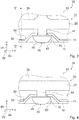
- Fig. 2
- a carrier unit, a room divider element and a housing component of the hob device in a schematic perspective view,
- Fig. 3
- a section from
Fig. 2 in an enlarged schematic plan view, - Fig. 4
- another section
Fig. 2 in an enlarged schematic plan view, - Fig. 5
- a section along the line VV in
Fig. 3 in a mounted state in a schematic representation and - Fig. 6
- a section along the line VI-VI in
Fig. 2 in a mounted state in a schematic representation.
Die Kochfeldvorrichtung 10 umfasst eine Touch-Bedieneinheit 22 zu einer Eingabe und/oder Auswahl von Betriebsparametern, beispielsweise einer Heizleistung und/oder einer Heizleistungsdichte und/oder einer Heizzone (vgl.
Die Kochfeldvorrichtung 10 umfasst eine Steuereinheit 40, die in Abhängigkeit von mittels der Touch-Bedieneinheit 22 eingegebenen Betriebsparametern Aktionen ausführt und/oder Einstellungen verändert. Die Steuereinheit 40 betreibt in einem Betriebszustand die Heizelemente in Abhängigkeit von mittels der Touch-Bedieneinheit 22 eingegebenen Betriebsparametern.The
Die Kochfeldvorrichtung 10 umfasst eine Gehäuseeinheit 14, die in dem montierten Zustand gemeinsam mit der Kochfeldplatte 12 ein Außengehäuse, und zwar ein Kochfeldaußengehäuse, ausbildet (vgl.
Zu einem Halten der Touch-Bedieneinheit 22 in der Einbaulage umfasst die Kochfeldvorrichtung 10 eine Trägereinheit 20. In dem montierten Zustand ist die Trägereinheit 20 in dem Lagerraum angeordnet. Die Trägereinheit 20, die für die Kochfeldvorrichtung 10 vorgesehen ist, hält in der Einbaulage die Touch-Bedieneinheit 22 in einer einem Bediener abgewandten Seite, und zwar einer Unterseite, der Kochfeldplatte 12. Hierbei hält die Trägereinheit 20 in der Einbaulage die Touch-Bedieneinheit 22 in einer Sollposition, die insbesondere durch die Markierungen an der Kochfeldplatte 12 angezeigt ist. Die Trägereinheit 20 weist einen Grundkörper 28 auf, oberhalb welchem in der Einbaulage die Touch-Bedieneinheit 22 aufgelegt ist.For holding the
Die Kochfeldvorrichtung 10 umfasst ein Raumteilerelement 36, oberhalb welchem die Trägereinheit 20 in dem montierten Zustand und in der Einbaulage aufgelegt ist. In dem montierten Zustand teilt das Raumteilerelement 36 den Lagerraum in zwei Teilräume auf. Das Raumteilerelement 36 ist in montiertem Zustand auf einem Teilabschnitt 42 des Gehäusebauteils 16 aufgelegt (vgl.
Das Raumteilerelement 36 weist an einem dem Gehäusebauteil 16 zugewandten Abschnitt einen Teilbereich 52 auf, der in dem montierten Zustand im Wesentlichen senkrecht zu der Kochfeldplatte 12 ausgerichtet ist (vgl.
In dem montierten Zustand ist die Gehäuseeinheit 14 zusätzlich in direktem Kontakt mit der Trägereinheit 20 angeordnet. Die Trägereinheit 20 ist in dem montierten Zustand an der Gehäuseeinheit 14 befestigt. Die Gehäuseeinheit 14 fixiert die Trägereinheit 20 in dem montierten Zustand in einer zu einer Haupterstreckungsebene der Kochfeldplatte 12 parallelen Richtung 24. Die zu der Haupterstreckungsebene der Kochfeldplatte 12 parallele Richtung 24 ist senkrecht zu einer Vorderkante der Kochfeldplatte 12 ausgerichtet und wird im Folgenden als Y-Richtung 24 bezeichnet. Eine weitere, ebenfalls zu der Haupterstreckungsebene der Kochfeldplatte 12 parallele Richtung 64 ist parallel der Vorderkante der Kochfeldplatte 12 ausgerichtet und wird im Folgenden als X-Richtung 64 bezeichnet.In the mounted state, the
Die Y-Richtung 24 ist im Wesentlichen senkrecht zu einer Oberfläche einer Seitenwand des Gehäusebauteils 16 ausgerichtet. Zudem ist die Y-Richtung 24 im Wesentlichen senkrecht zu einem der Kochfeldplatte 12 abgewandten Bereich des Seitenbauteils 18 ausgerichtet. Das Gehäusebauteil 16 und das Seitenbauteil 18 fixieren gemeinsam die Trägereinheit 20 in der zu der Haupterstreckungsebene der Kochfeldplatte 12 parallelen Y-Richtung 24 (vgl.
Die Kochfeldvorrichtung 10 umfasst zwei Eingriffselemente 26, die in dem montierten Zustand wirkverbunden mit der Trägereinheit 20 sind. Da die Eingriffselemente 26 im Wesentlichen identisch ausgebildet sind, wird im Folgenden lediglich eines der Eingriffselemente 26 beschrieben. Das Eingriffselement 26 und der Grundkörper 28 der Trägereinheit 20 sind einstückig ausgebildet. Das Eingriffselement 26 ist pilzartig ausgebildet. Hierbei weist das Eingriffselement 26 einen Verbindungsabschnitt 44 und einen Kopfabschnitt 46 auf. In dem montierten Zustand ist das Eingriffselement 26 mit dem Verbindungsabschnitt 44 an dem Grundkörper 28 angebunden. Zudem ist der Kopfabschnitt 46 dem Grundkörper 28 abgewandt. In dem montierten Zustand greift das Eingriffselement 26 teilweise durch das Gehäusebauteil 16 hindurch (vgl.
Das Gehäusebauteil 16 weist zwei Ausnehmungen 30, 32 zu einer Aufnahme des Eingriffselements 26 auf. Es sind verschiedene, einem Fachmann als sinnvoll erscheinende Ausgestaltungen der Ausnehmungen des Gehäusebauteils denkbar. Beispielsweise könnten die Ausnehmungen als im Wesentlichen geschlossene Ausnehmungen ausgebildet sein, die insbesondere von dem Gehäusebauteil in einer Oberflächenebene des Gehäusebauteils von allen Seiten und insbesondere über einen Winkel von mindestens 270°, insbesondere von mindestens 300°, vorteilhaft von mindestens 330°, besonders vorteilhaft von mindestens 350° umgeben sein könnten.The
Im vorliegenden Ausführungsbeispiel sind die Ausnehmungen 30, 32 jedoch teilweise geöffnet ausgebildet, wobei die Ausnehmungen 30, 32 insbesondere randseitig an dem Gehäusebauteil 16 angeordnet sind. Die Ausnehmungen 30, 32 des Gehäusebauteils 16 sind in einem in dem montierten Zustand der Kochfeldplatte 12 zugewandten Randbereich des Gehäusebauteils 16 angeordnet. In einem Bereich der Ausnehmungen 30, 32 weist das Gehäusebauteil 16 für jede Ausnehmung 30, 32 jeweils eine Wölbung 48, 50 auf, die in dem montierten Zustand in den Lagerraum hineinragen. In einem Bereich der Wölbungen 48, 50 weist das Raumteilerelement 36 jeweils eine Aussparung 54 auf, durch welche die Wölbungen 48, 50 in dem montierten Zustand hindurchgreifen (vgl.
Das Eingriffselement 26 ragt in der Y-Richtung 24 über die Ausnehmung 30, 32 des Gehäusebauteils 16 hinaus. Hierbei ragt ein Teil des Kopfabschnitts 46 in der Y-Richtung 24 über die Ausnehmung 30, 32 aus dem Gehäusebauteil 16 hinaus. Bei Befestigung des Seitenbauteils 18 und des Gehäusebauteils 16 aneinander wird das Eingriffselement 26 zwischen dem Gehäusebauteil 16 und dem Seitenbauteil 18 eingeklemmt. In dem montierten Zustand ist das Eingriffselement 26 damit zwischen dem Gehäusebauteil 16 und dem Seitenbauteil 18 im Wesentlichen formschlüssig und kraftschlüssig gehalten.The
Die Eingriffselemente 26 sind an zwei einander in der X-Richtung 64 gegenüberliegenden Seiten der Trägereinheit 20 angeordnet. Ein Abstand der Eingriffselemente 26 ist maximal gewählt, wobei ein Mindestabstand zu einem Rand der Trägereinheit 20 eingehalten wurde. Je größer ein Abstand zwischen den Eingriffselementen 26 gewählt ist, desto exakter ist eine Ausrichtung der Trägereinheit 20 relativ zu den Markierungen der Kochfeldplatte 12 in der X-Richtung 64. Die Ausnehmungen 30, 32 sind an zu den Eingriffselementen 26 korrespondierenden Stellen des Gehäusebauteils 16 und damit ebenfalls bezüglich der X-Richtung 64 voneinander beabstandet angeordnet. In dem montierten Zustand sind die Eingriffselemente 26 in den Ausnehmungen 30, 32 des Gehäusebauteils 16 eingehängt.The
Die Ausnehmungen 30, 32 sind unterschiedlich ausgebildet. Hierbei weisen die Ausnehmungen 30, 32 in der X-Richtung 64 unterschiedliche Erstreckungen auf. Eine erste Ausnehmung 30 der Ausnehmungen 30, 32 weist in der X-Richtung 64 eine Erstreckung auf, die unwesentlich größer ist als eine Erstreckung des Eingriffselements 26 in der X-Richtung 64, insbesondere als ein Durchmesser des Verbindungsabschnitts 44. Das Eingriffselement 26 ist in dem montierten Zustand formschlüssig in der ersten Ausnehmung 30 gelagert. Eine zweite Ausnehmung 32 der Ausnehmungen 30, 32 weist in der X-Richtung 64 eine größere Erstreckung auf als die erste Ausnehmung 30. Hierdurch können bei Einhängen der Eingriffselemente 26 Fertigungstoleranzen ausgeglichen werden. In dem montierten Zustand ist das Eingriffselement 26 mit Spiel in der zweiten Ausnehmung 32 gelagert (vgl.
Mittels der Ausnehmungen 30, 32 richtet das Gehäusebauteil 16 die Trägereinheit 20 und damit insbesondere die Touch-Bedieneinheit 22 in der X-Richtung 64 aus. Somit richtet die Gehäuseeinheit 14 die Trägereinheit 20 in dem montierten Zustand zusätzlich zu einer Ausrichtung in der Y-Richtung 24 in der zu der Haupterstreckungsebene der Kochfeldplatte 12 parallelen X-Richtung 64 aus. Die Gehäuseeinheit 14 ordnet die Trägereinheit 20 in dem montierten Zustand in der Sollposition an.By means of the
Die Kochfeldvorrichtung 10 umfasst zwei Kraftelemente 34, die in dem montierten Zustand wirkverbunden mit der Trägereinheit 20 sind. Da die Kraftelemente 34 im Wesentlichen identisch ausgebildet sind, wird im Folgenden lediglich eines der Kraftelemente 34 beschrieben. Das Kraftelement 34 ist in dem montierten Zustand mit einem Ende mit dem Grundkörper 28 verbunden. Ein dem Grundkörper 28 abgewandtes Ende des Kraftelements 34 ist beweglich relativ zu dem Grundkörper 28 der Trägereinheit 20 angeordnet. Das Kraftelement 34 und der Grundkörper 28 der Trägereinheit 20 sind einstückig ausgebildet. In dem montierten Zustand erzeugt das Kraftelement 34 eine auf die Trägereinheit 20 in der zu der Haupterstreckungsebene der Kochfeldplatte 12 parallelen y-Richtung 24 ausgerichtete Kraft. Hierbei drückt das Kraftelement 34 den Grundkörper 28 in der y-Richtung 24 von dem Gehäusebauteil 16 weg.
Zu der Erzeugung der Kraft in Y-Richtung 24 stützt sich das Kraftelement 34 in dem montierten Zustand an dem Gehäusebauteil 16 ab (vgl.
Das Kraftelement 34 und das Eingriffselement 26 sind in dem montierten Zustand auf einander gegenüberliegenden Seiten des Gehäusebauteils 16 angeordnet. Das Eingriffselement 26 erzeugt in dem montierten Zustand eine Gegenkraft zu der von dem Kraftelement 34 erzeugten Kraft. In dem montierten Zustand hält das Eingriffselement 26 den Grundkörper 28 an dem Gehäusebauteil 16 fest, wohingegen das Kraftelement 34 den Grundkörper 28 von dem Gehäusebauteil 16 wegdrückt. Dadurch kann die in der Einbaulage oberhalb des Grundkörpers 28 aufgelegte Touch-Bedieneinheit 22 in der Y-Richtung 24 präzise relativ zu den Markierungen auf der Kochfeldplatte 12 ausgerichtet werden.The
Das Kraftelement 34 ist aus elastischem Material ausgebildet. Hierbei ist das Kraftelement 34 aus demselben Material wie die Trägereinheit 20 und insbesondere wie der Grundkörper 28 ausgebildet. Die Trägereinheit 20 ist aus elektrisch isolierendem Material hergestellt. Beispielsweise könnte die Trägereinheit zumindest teilweise aus Polyamid, insbesondere aus einem aliphatischen Polyamid, beispielsweise Polyamid 6 und/oder Polyamid 66, ausgebildet sein. Ebenfalls denkbar ist, dass die Trägereinheit zumindest teilweise aus Polypropylen und/oder Polycarbonat ausgebildet ist. Alternativ sind weitere, einem Fachmann als sinnvoll erscheinende Kunststoffe und/oder Keramiken denkbar.The
Bei einem Verfahren zur Montage der Kochfeldvorrichtung 10 werden in einem ersten Verfahrensschritt zunächst die Kochfeldplatte 12 und das Seitenbauteil 18 der Gehäuseeinheit 14 miteinander verbunden. Das Seitenbauteil 18 wird maschinell an die Kochfeldplatte 12 geklebt, wodurch insbesondere eine genaue Positionierung des Seitenbauteils 18 an der Kochfeldplatte 12 erreicht werden kann. In einem weiteren Verfahrensschritt wird das Raumteilerelement 36 in das Gehäusebauteil 16 eingebracht. Das Raumteilerelement 36 wird auf den Teilabschnitt 42 des Gehäusebauteils 16 aufgelegt. In dieser Position ist das Raumteilerelement 36 formschlüssig zwischen Seitenwänden des Gehäusebauteils 16 gelagert, wobei der Teilbereich 52 mit den Seitenwänden in Anlage angeordnet ist. Anschließend wird die Trägereinheit 20 an dem Gehäusebauteil 16 befestigt. Hierbei wird die Trägereinheit 20 mit den Eingriffselementen 26 in den Ausnehmungen 30, 32 des Gehäusebauteils 16 eingehängt. Danach wird die Touch-Bedieneinheit 22 auf die Trägereinheit 20, und zwar insbesondere auf den Grundkörper 28, aufgelegt.In a method for assembling the
In einem weiteren Verfahrensschritt wird die Kochfeldplatte 12 mitsamt dem Seitenbauteil 18 dem Gehäusebauteil 16 parallel zu einer Z-Richtung 58 angenähert. Die Z-Richtung 58 ist senkrecht zu der Haupterstreckungsebene der Kochfeldplatte 12 ausgerichtet. Um bei der Montage eine Beschädigung des Eingriffselements 26 zu vermeiden, weist das Seitenbauteil 18 einen Vorsprung 60 auf. Der Vorsprung 60 ist als Einführhilfe ausgebildet und bildet hierzu eine Gleitfläche aus. In dem montierten Zustand des Seitenbauteils 18 an der Kochfeldplatte 12 ist der Vorsprung 60 schräg relativ zu der Haupterstreckungsebene der Kochfeldplatte 12 ausgerichtet. Mittels des Vorsprungs 60 können etwaige Ungenauigkeiten in einer Positionierung der Kochfeldplatte 12 relativ zu dem Gehäusebauteil 16 ausgeglichen werden. Die Kochfeldplatte 12 wird in der parallel zu der Z-Richtung 58 ausgerichteten Richtung bis in eine Endposition dem Gehäusebauteil 16 angenähert. In der Endposition werden das Gehäusebauteil 16 und das Seitenbauteil 18 miteinander verbunden. Hierbei werden das Gehäusebauteil 16 und das Seitenbauteil 18 miteinander verschraubt, wobei zeitlich der Grundkörper 28 der Trägereinheit 20 mit dem Gehäusebauteil 16 und dem Seitenbauteil 18 verschraubt wird. Insbesondere durchdringen Schrauben das Gehäusebauteil 16, das Seitenbauteil 18 sowie einen Teil des Grundkörpers 28. Hierdurch wird die Trägereinheit 20 in der zu der Haupterstreckungsebene der Kochfeldplatte 12 parallelen Y-Richtung 24 gemeinsam durch das Gehäusebauteil 16 und das Seitenbauteil 18 fixiert.In a further method step, the
In der Einbaulage hält die Trägereinheit 20 die Touch-Bedieneinheit 22 in der Sollposition. Die Trägereinheit 20 ist in der Einbaulage zu einer Ausrichtung der Touch-Bedieneinheit 22 in der Z-Richtung 58 vorgesehen. Die Trägereinheit 20 umfasst Federelemente 62. Im vorliegenden Fall umfasst die Trägereinheit 20 acht Federelemente 62, jedoch ist auch eine hiervon abweichende Anzahl denkbar. Die Federelemente 62 sind einstückig mit dem Grundkörper 28 der Trägereinheit 20 ausgebildet. Relativ zu dem Grundkörper 28 sind die Federelemente 62 beweglich gelagert. Die Federelemente 62 drücken in der Einbaulage die Touch-Bedieneinheit 22 in der Z-Richtung 58 gegen die Kochfeldplatte 12. Hierdurch kann eine funktionstüchtige Ausgestaltung erreicht werden, da Sensoren der Touch-Bedieneinheit 22 in einem Nahbereich und vorteilhaft in direktem Kontakt mit der Kochfeldplatte 12 angeordnet werden können.In the installed position, the
Beispielsweise könnte das Gehäusebauteil mehr als zwei Ausnehmungen und/oder Wölbungen zu einer Aufnahme des Eingriffselements aufweisen. Hierbei könnten insbesondere mehrere Eingriffselemente vorgesehen sein. Alternativ könnten die Ausnehmungen und/oder Wölbungen an weiteren vorteilhaften Positionen vorgesehen sein, wobei die Trägereinheit bei unterschiedlichen Ausgestaltungen und/oder Anordnungen von Markierungen auf der Kochfeldplatte in unterschiedlichen Positionen an dem Gehäusebauteil befestigt werden könnte. Ebenfalls denkbar ist, mehrere Trägereinheiten mittels der mehreren Ausnehmungen und/oder Wölbungen an dem Gehäusebauteil zu befestigen.For example, the housing component could have more than two recesses and / or bulges for receiving the engagement element. In this case, in particular a plurality of engagement elements could be provided. Alternatively, the recesses and / or bulges could be provided at further advantageous positions, wherein the support unit could be secured in different positions on the housing component in different configurations and / or arrangements of markings on the hob plate. It is also conceivable to fasten a plurality of carrier units to the housing component by means of the plurality of recesses and / or bulges.
- 1010
- KochfeldvorrichtungHob device
- 1212
- KochfeldplatteHotplate
- 1414
- Gehäuseeinheithousing unit
- 1616
- Gehäusebauteilhousing component
- 1818
- Seitenbauteilside component
- 2020
- Trägereinheitsupport unit
- 2222
- Touch-BedieneinheitTouch control unit
- 2424
- Richtungdirection
- 2626
- Eingriffselementengaging member
- 2828
- Grundkörperbody
- 3030
- Ausnehmungrecess
- 3232
- Ausnehmungrecess
- 3434
- Kraftelementforce member
- 3636
- RaumteilerelementRoom divider element
- 3838
- Kochfeldhob
- 4040
- Steuereinheitcontrol unit
- 4242
- Teilabschnittpart Of
- 4444
- Verbindungsabschnittconnecting portion
- 4646
- Kopfabschnittheader
- 4848
- Wölbungbulge
- 5050
- Wölbungbulge
- 5252
- Teilbereichsubregion
- 5454
- Aussparungrecess
- 5656
- Öffnungopening
- 5858
- Richtungdirection
- 6060
- Vorsprunghead Start
- 6262
- Federelementspring element
- 6464
- Richtungdirection
Claims (9)
- Hotplate device, in particular induction hotplate device, having a hotplate (12) with a housing unit (14), which, in an assembled state together with the hotplate (12), embodies an outer housing and which has at least one housing component (16) and at least one side component (18), which is provided to be connected to the at least one housing component (16) and to the hotplate (12), and with at least one support unit (20), which, in the assembled state, is fastened to the housing unit (14) and in a built-in position is provided to hold at least one touch control unit (22), wherein the at least one housing component (16) and the at least one side component (18) are together provided to fix the at least one support unit (20) at least in a direction (24) parallel to a main extension plane of the hotplate (12), and with at least one engagement element (26) which is actively connected to the at least one support unit (20) in the assembled state, which is provided to extend at least partially through the housing component (16), characterised in that the at least one support unit (20) and the at least one engagement element (26) are embodied in one piece.
- Hotplate device according to one of the preceding claims, characterised in that the at least one engagement element (26) in the assembled state is suspended at least in at least one recess (30, 32) of the at least one housing component (16).
- Hotplate device according to one of the preceding claims, characterised in that the at least one engagement element (26) is held at least in a substantially form-fit manner in the assembled state between the at least one housing component (16) and the at least one side component (18).
- Hotplate device according to one of the preceding claims,
characterised by at least one force element (34) actively connected to the at least one support unit (20), which is provided to generate a force acting on the at least one support unit (20) in a direction (24) parallel to the main extension plane of the hotplate (12). - Hotplate device at least according to claim 4, characterised in that the at least one engagement element (26) is provided to generate a counter force with respect to the force generated by the at least one force element (34).
- Hotplate device according to one of the preceding claims, characterised by at least one room divider element (36), above which the at least one support unit (20) is placed in the assembled state and in the built-in position.
- Support unit for a hotplate device (10) according to one of the preceding claims,
- Hotplate with at least one hotplate device (10) according to one of claims 1 to 6.
- Method for assembling a hotplate device (10), in particular an induction hotplate device, according to one of claims 1 to 6, with a hotplate (12), with a housing unit (14), which in an assembled state together with the hotplate (12) embodies an outer housing and which has at least one housing component (16) and at least one side component (18), which is connected to the at least one housing component (16) and to the hotplate (12), and with at least one support unit (20), which, in the assembled state, is fastened to the housing unit (14) and in a built-in position is provided to hold at least one touch control unit (22), and with at least one engagement element (26) which is actively connected to the at least one support unit (20) in the assembled state, which is provided to extend at least partially through the housing component (16), wherein the at least one support unit (20) is fixed at least in a direction (24) parallel to a main extension plane of the hotplate (12) mutually by the at least one housing component (16) and the at least one side component (18), characterised in that the at least one support unit (20) and the at least one engagement element (26) are embodied in one piece.
Applications Claiming Priority (1)
| Application Number | Priority Date | Filing Date | Title |
|---|---|---|---|
| ES201331788A ES2537503B1 (en) | 2013-12-05 | 2013-12-05 | Cooking Field Device |
Publications (2)
| Publication Number | Publication Date |
|---|---|
| EP2881671A1 EP2881671A1 (en) | 2015-06-10 |
| EP2881671B1 true EP2881671B1 (en) | 2019-03-20 |
Family
ID=51951730
Family Applications (1)
| Application Number | Title | Priority Date | Filing Date |
|---|---|---|---|
| EP14195005.5A Active EP2881671B1 (en) | 2013-12-05 | 2014-11-26 | Hotplate device |
Country Status (2)
| Country | Link |
|---|---|
| EP (1) | EP2881671B1 (en) |
| ES (2) | ES2537503B1 (en) |
Family Cites Families (11)
| Publication number | Priority date | Publication date | Assignee | Title |
|---|---|---|---|---|
| US4413611A (en) * | 1981-05-04 | 1983-11-08 | Raytheon Company | Modular gas range compartment |
| DE3141996C2 (en) * | 1981-10-22 | 1985-10-24 | Bosch-Siemens Hausgeräte GmbH, 7000 Stuttgart | Cooking panel |
| EP0124022B1 (en) * | 1983-04-30 | 1989-06-07 | Schott Glaswerke | Cooker hob with gas heated hot plates and a continuous cooking area of glass-ceramic or similar material |
| DE102006024739B4 (en) * | 2006-05-26 | 2012-04-12 | Electrolux Home Products Corporation N.V. | Household appliance, in particular household oven |
| DE102007021939A1 (en) * | 2007-05-10 | 2008-11-13 | BSH Bosch und Siemens Hausgeräte GmbH | hob |
| DE102008044235B4 (en) * | 2008-12-01 | 2011-06-30 | BSH Bosch und Siemens Hausgeräte GmbH, 81739 | Hob with a hob plate, which is connected to a mounting frame, and method for producing a hob |
| EP2317230A1 (en) * | 2009-05-02 | 2011-05-04 | Electrolux Home Products Corporation N.V. | Cooking hob with protection element |
| JP5496546B2 (en) * | 2009-05-29 | 2014-05-21 | 三洋電機株式会社 | Induction heating cooker |
| EP2427032B1 (en) * | 2010-09-06 | 2016-12-21 | BSH Hausgeräte GmbH | Hotplate device |
| EP2578949B1 (en) * | 2011-10-03 | 2018-12-26 | BSH Hausgeräte GmbH | Household appliance with at least one carrier unit having at least one spring unit |
| DE102012219265A1 (en) * | 2011-11-16 | 2013-05-16 | BSH Bosch und Siemens Hausgeräte GmbH | Home appliance device |
-
2013
- 2013-12-05 ES ES201331788A patent/ES2537503B1/en not_active Revoked
-
2014
- 2014-11-26 EP EP14195005.5A patent/EP2881671B1/en active Active
- 2014-11-26 ES ES14195005T patent/ES2718210T3/en active Active
Non-Patent Citations (1)
| Title |
|---|
| None * |
Also Published As
| Publication number | Publication date |
|---|---|
| ES2537503B1 (en) | 2016-03-23 |
| ES2718210T3 (en) | 2019-06-28 |
| ES2537503A1 (en) | 2015-06-08 |
| EP2881671A1 (en) | 2015-06-10 |
Similar Documents
| Publication | Publication Date | Title |
|---|---|---|
| DE10216225A1 (en) | Electromagnetic locking system of a safety switch | |
| WO2015049602A1 (en) | Hob apparatus | |
| DE102009006529A1 (en) | position sensor | |
| EP2703735B1 (en) | Household appliance having a microwave device | |
| EP1975518A2 (en) | Device for fixing a heater | |
| EP2816869B1 (en) | Hotplate device | |
| EP2602556A2 (en) | Hotplate device | |
| DE202010015731U1 (en) | Support device for an electrical terminal block assembly | |
| EP1929840B1 (en) | Maintaining arrangement for a hob of a cooking appliance | |
| EP2881671B1 (en) | Hotplate device | |
| EP1687571B1 (en) | Household appliance comprising an operating strip | |
| EP2765827B1 (en) | Hotplate device | |
| EP3029381B1 (en) | Hotplate device | |
| DE102005061827B4 (en) | computer case | |
| EP2881668B1 (en) | Gas hob device | |
| EP2881670B1 (en) | Hotplate device | |
| DE102007012481A1 (en) | Cooking area has ornamental frame and mounting frame, between which cooking area plate is arranged, where connecting device is provided with connection between ornamental frame and mounting frame | |
| DE102013113974A1 (en) | Holding frame for a connector | |
| EP2843315A2 (en) | Method for putting together at least one domestic appliance and domestic appliance | |
| EP2849532B1 (en) | Cooking hob | |
| DE102007020313A1 (en) | Device for monitoring state of protection device of machine, has reading head and actuator, which cooperates with reading head in closed state of protection device | |
| EP3386272A1 (en) | Hotplate device | |
| EP1970633B1 (en) | Rail pull-out device and oven muffle with such a rail pull-out device | |
| DE102006042177A1 (en) | oven | |
| EP3062398B1 (en) | Cooking hob device |
Legal Events
| Date | Code | Title | Description |
|---|---|---|---|
| PUAI | Public reference made under article 153(3) epc to a published international application that has entered the european phase |
Free format text: ORIGINAL CODE: 0009012 |
|
| 17P | Request for examination filed |
Effective date: 20141126 |
|
| AK | Designated contracting states |
Kind code of ref document: A1 Designated state(s): AL AT BE BG CH CY CZ DE DK EE ES FI FR GB GR HR HU IE IS IT LI LT LU LV MC MK MT NL NO PL PT RO RS SE SI SK SM TR |
|
| AX | Request for extension of the european patent |
Extension state: BA ME |
|
| R17P | Request for examination filed (corrected) |
Effective date: 20151210 |
|
| RBV | Designated contracting states (corrected) |
Designated state(s): AL AT BE BG CH CY CZ DE DK EE ES FI FR GB GR HR HU IE IS IT LI LT LU LV MC MK MT NL NO PL PT RO RS SE SI SK SM TR |
|
| STAA | Information on the status of an ep patent application or granted ep patent |
Free format text: STATUS: EXAMINATION IS IN PROGRESS |
|
| 17Q | First examination report despatched |
Effective date: 20170216 |
|
| GRAP | Despatch of communication of intention to grant a patent |
Free format text: ORIGINAL CODE: EPIDOSNIGR1 |
|
| STAA | Information on the status of an ep patent application or granted ep patent |
Free format text: STATUS: GRANT OF PATENT IS INTENDED |
|
| INTG | Intention to grant announced |
Effective date: 20181030 |
|
| GRAS | Grant fee paid |
Free format text: ORIGINAL CODE: EPIDOSNIGR3 |
|
| GRAA | (expected) grant |
Free format text: ORIGINAL CODE: 0009210 |
|
| STAA | Information on the status of an ep patent application or granted ep patent |
Free format text: STATUS: THE PATENT HAS BEEN GRANTED |
|
| AK | Designated contracting states |
Kind code of ref document: B1 Designated state(s): AL AT BE BG CH CY CZ DE DK EE ES FI FR GB GR HR HU IE IS IT LI LT LU LV MC MK MT NL NO PL PT RO RS SE SI SK SM TR |
|
| REG | Reference to a national code |
Ref country code: GB Ref legal event code: FG4D Free format text: NOT ENGLISH |
|
| REG | Reference to a national code |
Ref country code: CH Ref legal event code: EP |
|
| REG | Reference to a national code |
Ref country code: DE Ref legal event code: R096 Ref document number: 502014011174 Country of ref document: DE |
|
| REG | Reference to a national code |
Ref country code: AT Ref legal event code: REF Ref document number: 1110945 Country of ref document: AT Kind code of ref document: T Effective date: 20190415 |
|
| REG | Reference to a national code |
Ref country code: IE Ref legal event code: FG4D Free format text: LANGUAGE OF EP DOCUMENT: GERMAN |
|
| REG | Reference to a national code |
Ref country code: ES Ref legal event code: FG2A Ref document number: 2718210 Country of ref document: ES Kind code of ref document: T3 Effective date: 20190628 |
|
| REG | Reference to a national code |
Ref country code: NL Ref legal event code: FP |
|
| PG25 | Lapsed in a contracting state [announced via postgrant information from national office to epo] |
Ref country code: LT Free format text: LAPSE BECAUSE OF FAILURE TO SUBMIT A TRANSLATION OF THE DESCRIPTION OR TO PAY THE FEE WITHIN THE PRESCRIBED TIME-LIMIT Effective date: 20190320 Ref country code: SE Free format text: LAPSE BECAUSE OF FAILURE TO SUBMIT A TRANSLATION OF THE DESCRIPTION OR TO PAY THE FEE WITHIN THE PRESCRIBED TIME-LIMIT Effective date: 20190320 Ref country code: NO Free format text: LAPSE BECAUSE OF FAILURE TO SUBMIT A TRANSLATION OF THE DESCRIPTION OR TO PAY THE FEE WITHIN THE PRESCRIBED TIME-LIMIT Effective date: 20190620 Ref country code: FI Free format text: LAPSE BECAUSE OF FAILURE TO SUBMIT A TRANSLATION OF THE DESCRIPTION OR TO PAY THE FEE WITHIN THE PRESCRIBED TIME-LIMIT Effective date: 20190320 |
|
| REG | Reference to a national code |
Ref country code: LT Ref legal event code: MG4D |
|
| PG25 | Lapsed in a contracting state [announced via postgrant information from national office to epo] |
Ref country code: LV Free format text: LAPSE BECAUSE OF FAILURE TO SUBMIT A TRANSLATION OF THE DESCRIPTION OR TO PAY THE FEE WITHIN THE PRESCRIBED TIME-LIMIT Effective date: 20190320 Ref country code: RS Free format text: LAPSE BECAUSE OF FAILURE TO SUBMIT A TRANSLATION OF THE DESCRIPTION OR TO PAY THE FEE WITHIN THE PRESCRIBED TIME-LIMIT Effective date: 20190320 Ref country code: HR Free format text: LAPSE BECAUSE OF FAILURE TO SUBMIT A TRANSLATION OF THE DESCRIPTION OR TO PAY THE FEE WITHIN THE PRESCRIBED TIME-LIMIT Effective date: 20190320 Ref country code: BG Free format text: LAPSE BECAUSE OF FAILURE TO SUBMIT A TRANSLATION OF THE DESCRIPTION OR TO PAY THE FEE WITHIN THE PRESCRIBED TIME-LIMIT Effective date: 20190620 Ref country code: GR Free format text: LAPSE BECAUSE OF FAILURE TO SUBMIT A TRANSLATION OF THE DESCRIPTION OR TO PAY THE FEE WITHIN THE PRESCRIBED TIME-LIMIT Effective date: 20190621 |
|
| PG25 | Lapsed in a contracting state [announced via postgrant information from national office to epo] |
Ref country code: SK Free format text: LAPSE BECAUSE OF FAILURE TO SUBMIT A TRANSLATION OF THE DESCRIPTION OR TO PAY THE FEE WITHIN THE PRESCRIBED TIME-LIMIT Effective date: 20190320 Ref country code: PT Free format text: LAPSE BECAUSE OF FAILURE TO SUBMIT A TRANSLATION OF THE DESCRIPTION OR TO PAY THE FEE WITHIN THE PRESCRIBED TIME-LIMIT Effective date: 20190720 Ref country code: RO Free format text: LAPSE BECAUSE OF FAILURE TO SUBMIT A TRANSLATION OF THE DESCRIPTION OR TO PAY THE FEE WITHIN THE PRESCRIBED TIME-LIMIT Effective date: 20190320 Ref country code: AL Free format text: LAPSE BECAUSE OF FAILURE TO SUBMIT A TRANSLATION OF THE DESCRIPTION OR TO PAY THE FEE WITHIN THE PRESCRIBED TIME-LIMIT Effective date: 20190320 Ref country code: CZ Free format text: LAPSE BECAUSE OF FAILURE TO SUBMIT A TRANSLATION OF THE DESCRIPTION OR TO PAY THE FEE WITHIN THE PRESCRIBED TIME-LIMIT Effective date: 20190320 Ref country code: IT Free format text: LAPSE BECAUSE OF FAILURE TO SUBMIT A TRANSLATION OF THE DESCRIPTION OR TO PAY THE FEE WITHIN THE PRESCRIBED TIME-LIMIT Effective date: 20190320 Ref country code: EE Free format text: LAPSE BECAUSE OF FAILURE TO SUBMIT A TRANSLATION OF THE DESCRIPTION OR TO PAY THE FEE WITHIN THE PRESCRIBED TIME-LIMIT Effective date: 20190320 |
|
| PG25 | Lapsed in a contracting state [announced via postgrant information from national office to epo] |
Ref country code: SM Free format text: LAPSE BECAUSE OF FAILURE TO SUBMIT A TRANSLATION OF THE DESCRIPTION OR TO PAY THE FEE WITHIN THE PRESCRIBED TIME-LIMIT Effective date: 20190320 Ref country code: PL Free format text: LAPSE BECAUSE OF FAILURE TO SUBMIT A TRANSLATION OF THE DESCRIPTION OR TO PAY THE FEE WITHIN THE PRESCRIBED TIME-LIMIT Effective date: 20190320 |
|
| PG25 | Lapsed in a contracting state [announced via postgrant information from national office to epo] |
Ref country code: IS Free format text: LAPSE BECAUSE OF FAILURE TO SUBMIT A TRANSLATION OF THE DESCRIPTION OR TO PAY THE FEE WITHIN THE PRESCRIBED TIME-LIMIT Effective date: 20190720 |
|
| REG | Reference to a national code |
Ref country code: DE Ref legal event code: R097 Ref document number: 502014011174 Country of ref document: DE |
|
| PLBE | No opposition filed within time limit |
Free format text: ORIGINAL CODE: 0009261 |
|
| STAA | Information on the status of an ep patent application or granted ep patent |
Free format text: STATUS: NO OPPOSITION FILED WITHIN TIME LIMIT |
|
| PG25 | Lapsed in a contracting state [announced via postgrant information from national office to epo] |
Ref country code: DK Free format text: LAPSE BECAUSE OF FAILURE TO SUBMIT A TRANSLATION OF THE DESCRIPTION OR TO PAY THE FEE WITHIN THE PRESCRIBED TIME-LIMIT Effective date: 20190320 |
|
| 26N | No opposition filed |
Effective date: 20200102 |
|
| PG25 | Lapsed in a contracting state [announced via postgrant information from national office to epo] |
Ref country code: SI Free format text: LAPSE BECAUSE OF FAILURE TO SUBMIT A TRANSLATION OF THE DESCRIPTION OR TO PAY THE FEE WITHIN THE PRESCRIBED TIME-LIMIT Effective date: 20190320 |
|
| PG25 | Lapsed in a contracting state [announced via postgrant information from national office to epo] |
Ref country code: TR Free format text: LAPSE BECAUSE OF FAILURE TO SUBMIT A TRANSLATION OF THE DESCRIPTION OR TO PAY THE FEE WITHIN THE PRESCRIBED TIME-LIMIT Effective date: 20190320 |
|
| REG | Reference to a national code |
Ref country code: CH Ref legal event code: PL |
|
| PG25 | Lapsed in a contracting state [announced via postgrant information from national office to epo] |
Ref country code: CH Free format text: LAPSE BECAUSE OF NON-PAYMENT OF DUE FEES Effective date: 20191130 Ref country code: MC Free format text: LAPSE BECAUSE OF FAILURE TO SUBMIT A TRANSLATION OF THE DESCRIPTION OR TO PAY THE FEE WITHIN THE PRESCRIBED TIME-LIMIT Effective date: 20190320 Ref country code: LI Free format text: LAPSE BECAUSE OF NON-PAYMENT OF DUE FEES Effective date: 20191130 Ref country code: LU Free format text: LAPSE BECAUSE OF NON-PAYMENT OF DUE FEES Effective date: 20191126 |
|
| REG | Reference to a national code |
Ref country code: BE Ref legal event code: MM Effective date: 20191130 |
|
| PG25 | Lapsed in a contracting state [announced via postgrant information from national office to epo] |
Ref country code: IE Free format text: LAPSE BECAUSE OF NON-PAYMENT OF DUE FEES Effective date: 20191126 |
|
| PG25 | Lapsed in a contracting state [announced via postgrant information from national office to epo] |
Ref country code: BE Free format text: LAPSE BECAUSE OF NON-PAYMENT OF DUE FEES Effective date: 20191130 |
|
| REG | Reference to a national code |
Ref country code: AT Ref legal event code: MM01 Ref document number: 1110945 Country of ref document: AT Kind code of ref document: T Effective date: 20191126 |
|
| PG25 | Lapsed in a contracting state [announced via postgrant information from national office to epo] |
Ref country code: AT Free format text: LAPSE BECAUSE OF NON-PAYMENT OF DUE FEES Effective date: 20191126 |
|
| PG25 | Lapsed in a contracting state [announced via postgrant information from national office to epo] |
Ref country code: CY Free format text: LAPSE BECAUSE OF FAILURE TO SUBMIT A TRANSLATION OF THE DESCRIPTION OR TO PAY THE FEE WITHIN THE PRESCRIBED TIME-LIMIT Effective date: 20190320 |
|
| PG25 | Lapsed in a contracting state [announced via postgrant information from national office to epo] |
Ref country code: MT Free format text: LAPSE BECAUSE OF FAILURE TO SUBMIT A TRANSLATION OF THE DESCRIPTION OR TO PAY THE FEE WITHIN THE PRESCRIBED TIME-LIMIT Effective date: 20190320 Ref country code: HU Free format text: LAPSE BECAUSE OF FAILURE TO SUBMIT A TRANSLATION OF THE DESCRIPTION OR TO PAY THE FEE WITHIN THE PRESCRIBED TIME-LIMIT; INVALID AB INITIO Effective date: 20141126 |
|
| PG25 | Lapsed in a contracting state [announced via postgrant information from national office to epo] |
Ref country code: MK Free format text: LAPSE BECAUSE OF FAILURE TO SUBMIT A TRANSLATION OF THE DESCRIPTION OR TO PAY THE FEE WITHIN THE PRESCRIBED TIME-LIMIT Effective date: 20190320 |
|
| REG | Reference to a national code |
Ref country code: DE Ref legal event code: R084 Ref document number: 502014011174 Country of ref document: DE |
|
| PGFP | Annual fee paid to national office [announced via postgrant information from national office to epo] |
Ref country code: NL Payment date: 20231122 Year of fee payment: 10 |
|
| PGFP | Annual fee paid to national office [announced via postgrant information from national office to epo] |
Ref country code: GB Payment date: 20231123 Year of fee payment: 10 |
|
| PGFP | Annual fee paid to national office [announced via postgrant information from national office to epo] |
Ref country code: ES Payment date: 20231215 Year of fee payment: 10 |
|
| PGFP | Annual fee paid to national office [announced via postgrant information from national office to epo] |
Ref country code: FR Payment date: 20231123 Year of fee payment: 10 Ref country code: DE Payment date: 20231130 Year of fee payment: 10 |