EP2881642B2 - Schutzkappe - Google Patents
Schutzkappe Download PDFInfo
- Publication number
- EP2881642B2 EP2881642B2 EP14193204.6A EP14193204A EP2881642B2 EP 2881642 B2 EP2881642 B2 EP 2881642B2 EP 14193204 A EP14193204 A EP 14193204A EP 2881642 B2 EP2881642 B2 EP 2881642B2
- Authority
- EP
- European Patent Office
- Prior art keywords
- protective cap
- region
- stem
- diameter
- disengagement device
- Prior art date
- Legal status (The legal status is an assumption and is not a legal conclusion. Google has not performed a legal analysis and makes no representation as to the accuracy of the status listed.)
- Active
Links
- 230000001681 protective effect Effects 0.000 claims description 57
- 239000000463 material Substances 0.000 claims description 9
- 229920003023 plastic Polymers 0.000 claims description 7
- 239000004033 plastic Substances 0.000 claims description 7
- 238000007789 sealing Methods 0.000 claims description 6
- 230000004323 axial length Effects 0.000 claims description 5
- 238000009434 installation Methods 0.000 description 9
- 230000008878 coupling Effects 0.000 description 7
- 238000010168 coupling process Methods 0.000 description 7
- 238000005859 coupling reaction Methods 0.000 description 7
- 238000011109 contamination Methods 0.000 description 2
- 239000013013 elastic material Substances 0.000 description 2
- 239000012530 fluid Substances 0.000 description 2
- 238000004519 manufacturing process Methods 0.000 description 2
- 239000002245 particle Substances 0.000 description 2
- 230000007423 decrease Effects 0.000 description 1
- 229920002457 flexible plastic Polymers 0.000 description 1
- 238000011084 recovery Methods 0.000 description 1
- 238000000926 separation method Methods 0.000 description 1
Images
Classifications
-
- F—MECHANICAL ENGINEERING; LIGHTING; HEATING; WEAPONS; BLASTING
- F16—ENGINEERING ELEMENTS AND UNITS; GENERAL MEASURES FOR PRODUCING AND MAINTAINING EFFECTIVE FUNCTIONING OF MACHINES OR INSTALLATIONS; THERMAL INSULATION IN GENERAL
- F16L—PIPES; JOINTS OR FITTINGS FOR PIPES; SUPPORTS FOR PIPES, CABLES OR PROTECTIVE TUBING; MEANS FOR THERMAL INSULATION IN GENERAL
- F16L55/00—Devices or appurtenances for use in, or in connection with, pipes or pipe systems
- F16L55/10—Means for stopping flow in pipes or hoses
- F16L55/115—Caps
-
- F—MECHANICAL ENGINEERING; LIGHTING; HEATING; WEAPONS; BLASTING
- F16—ENGINEERING ELEMENTS AND UNITS; GENERAL MEASURES FOR PRODUCING AND MAINTAINING EFFECTIVE FUNCTIONING OF MACHINES OR INSTALLATIONS; THERMAL INSULATION IN GENERAL
- F16L—PIPES; JOINTS OR FITTINGS FOR PIPES; SUPPORTS FOR PIPES, CABLES OR PROTECTIVE TUBING; MEANS FOR THERMAL INSULATION IN GENERAL
- F16L2201/00—Special arrangements for pipe couplings
- F16L2201/80—Dust covers
Definitions
- the invention relates to a hydraulic release device for a friction clutch of a motor vehicle with a protective cap for a fluid-conducting connection port, in particular a release device used in a clutch bell, wherein the protective cap has at least one fastening region cooperating with the connection port.
- the publication DE 197 16 473 C2 shows such a hydraulic release device in the form of a central release mechanism for a friction clutch.
- protective caps are placed on the connection ports of the hydraulic system - usually with a force fit.
- the protective caps prevent fluid from escaping and dirt particles from entering the system.
- the protective cap is removed from the connection port in order to connect it to a further line, for example.
- the protective cap must be removed in a controlled manner immediately before assembly or connection of the connection port to the system.
- Such a dirt cap is described in the publication EP 2 657 586 A2 described, whereby the dirt cap has a type of plug that is pushed into a hydraulic line or connector, as well as a cap that is positioned radially outside the line or connector. In hard-to-reach places, access to the protective caps is often not possible.
- the EN 10 2010 043 438 A1 describes, for example, a protective cap for a fluid-carrying connection of a hydraulic system, which, in addition to a relatively weak force-fitting connection to ensure the necessary tightness, also provides a detachable form-fitting connection between a fastening area of the protective cap and the connection connection.
- a section of the fastening area is designed as at least one thread.
- the protective cap which is designed by means of a thread to be screwed on during assembly and off the connection closure during disassembly, takes up little space. However, it cannot be used in very limited radial installation space, such as in a clutch bell of a friction clutch in a motor vehicle. Here, there is too little space in the radial direction for manual or mechanical access to the protective cap in order to screw it onto the connection connection or unscrew it during disassembly.
- the object of the invention is therefore to provide a hydraulic release device for a friction clutch of a motor vehicle with a protective cap for a fluid-conducting connection port, in particular a hydraulically operated release device inserted in a clutch bell, which enables easy assembly/disassembly in the smallest of spaces and ensures good sealing at least against low pressures.
- a protective cap for a fluid-conducting connection connection, the protective cap having at least one fastening area that interacts with the connection connection, the fastening area being adjoined on the side facing away from the connection connection by an elastically bendable, resilient grip area that can be folded sideways in a resilient manner when there is mechanical resistance and can be raised to its starting position when the resistance is removed, and the grip area, which consists of a shaft adjoining the fastening area in the direction of a longitudinal axis and a head piece formed at the end of the shaft, can be resiliently tilted by a tilt angle in relation to the longitudinal axis and the shaft has a diameter that is greatly reduced compared to the diameter of the fastening area.
- At least the shaft is made of an elastic plastic material.
- the axial length of the grip area is preferably several times larger than the diameter of the shaft.
- the headpiece has a diameter formed by an extension of the shaft.
- the fastening region has means for sealing on its side facing the connection port.
- the protective cap is rotationally symmetrical.
- the fastening area and the grip area are made in one piece from an elastic Plastic material.
- the fastening area and the handle area can also be made of different materials.
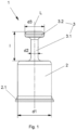
- a protective cap 1 is shown in a schematic representation.
- the protective cap 1 can be used, for example, in a clutch bell K of a friction clutch of a motor vehicle and serves to seal off a fluid-carrying connection port V of a release device during transport and/or assembly/dismantling.
- This application area of the protective cap 1 is in Fig. 2 and Fig. 3
- the application of the protective cap 1 is not limited to the area described.
- the protective cap 1 is preferably a rotationally symmetrical component made of an elastic plastic, which consists of a pot-shaped fastening area 2 and a handle area 3.
- the handle area 3 comprises a shaft 3.1 and a head piece 3.2, wherein the shaft 3.1 extending in the direction of a longitudinal axis L creates a connection between the fastening area 2 and the head piece 3.2.
- the shaft 3.1 which is formed by a strong reduction in diameter compared to the fastening area 2, which has a diameter d1, has a relatively small diameter d2 in relation to an axial length l of the handle area 3.
- the head piece 3.2 which is preferably designed with a flattened front side, has a slightly larger diameter d3 compared to the shaft 3.1.
- the grip area 3 When using an elastic, resilient plastic material - at least for the shaft 3.1 - the grip area 3 with the geometry has a tilting ability about the longitudinal axis L in conjunction with an elastic recovery ability in the direction of the longitudinal axis L.
- the fastening area 2 has a circumferential flange 2.1 on its open side facing away from the handle area 3, the arrangement of which is given here as an example for the use of further means for sealing against at least low pressures which arise during transport and/or during assembly/dismantling at the connection connection V (see Fig.3 ).
- Such means are a sealing lip-shaped design of the flange 2.1.
- the flange 2.1 also facilitates mounting (putting over) the protective cap 1 on the connection port V.
- the diameter d1 of the fastening area 2, which is essentially cylindrical and preferably made of an elastic material, is selected such that it approximately corresponds to the diameter of the connection port V to be closed or is slightly larger.
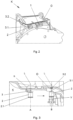
- the Fig.2 shows the use of the protective cap 1 in the coupling bell K.
- Two protective caps 1 are indicated here, which are attached to connection connections V (not shown here) and each protrude from an opening O in the coupling bell K.
- connection connections V not shown here
- the protective cap 1 In order to create a connection to a further line or a connection part (not shown) outside the coupling bell K, the protective cap 1 must be removed. This is easy to do because the geometry of the handle area 3 - with the narrow shaft 3.1 and the head piece 3.2 sitting on it - enables good handling, i.e. the head piece 3.2 can be easily gripped both manually and mechanically and the protective cap 1 can therefore be easily removed.
- Fig. 3 the protective cap 1 is shown during assembly of the release device in the clutch bell K.
- the complete release device (not shown here) with associated connection port V is inserted axially into the clutch bell K as a pre-assembled unit.
- the connection port V is located on a pressure line (not shown here in detail), which bridges a radial distance between the release device and the clutch bell K.
- the line or the connection port V must remain closed using the protective cap 1.
- the connection port V located in the clutch bell K must be closed again using the protective cap 1 to avoid contamination. This means that the connection port V with the protective cap 1 attached to it must be moved towards the opening O when assembling the system/release device when the radial installation space in the clutch bell K is very limited and must be moved away from the opening when disassembling.
- Fig.3 To explain the mode of operation of the protective cap 1, a movement of the connecting connection V in the coupling bell K from a position A to a position B is shown.
- the mounting direction is indicated by the arrow.
- the connection port V is not shown in position A.
- the connecting port V with the protective cap 1 In position B, the connecting port V with the protective cap 1 is in an end position associated with the opening O of the clutch bell K, in which end position the protective cap 1 can be removed from the connecting port V and this can be connected to the connecting part (not shown here) arranged outside the clutch bell K.
- the protective cap 1 located on the connection V must be moved along a coupling bell wall representing the radial installation space limitation, which is located at a distance from the fastening area 2 of the protective cap 1 that is smaller than the axial length l of the handle area 3. Due to the elastic bendability of the handle area 3 of the protective cap 1, the shaft 3.1 with the head piece 3.2 bends laterally at least partially - depending on the distance to the coupling bell wall - in a spring-loaded manner as soon as the radial installation space limitation is present as a mechanical resistance or obstacle.
- the tilting angle ⁇ i.e. how far the handle area 3 tilts from the upright starting position directed in the direction of the longitudinal axis L into a lateral avoidance position, depends on the dimensions of the protective cap 1 and on the radial installation space (distance) in the clutch bell K. If, for example, there is more space for the protective cap 1, the handle area 3 only has to tilt to the side at a smaller tilting angle ⁇ than in a narrow installation space.
- the protective cap 1 When the protective cap 1 (with the connection V) continues to move in the direction of the arrow, the protective cap 1 reaches the position B opposite the opening O. This increases the radial installation space and the grip area 3 (shaft 3.1 with the head piece 3.2) can straighten up again in the direction of the longitudinal axis L due to its spring-elastic design.
- the protective cap 1 is now in the position shown in Fig.2 shown position, in which the head piece 3.2 looks out of the opening O and is therefore easy to handle or dismantle. This also applies vice versa to the separation of the system from the connection part located outside the coupling bell K, whereby the protective cap 1 must be put back on or mounted on the connection connection V.
- the design of the protective cap 1 - here in particular the head piece 3.2 - enables good handling during its manual or mechanical assembly.
- the design of the shaft 3.1 (in conjunction with the elastic material) enables it to be folded over and straightened up again in a springy manner.
- the strength-optimized design of the grip area 3 (shaft 3.1 and head piece 3.2) also allows disassembly forces to be better absorbed.
- the design of the protective cap 1 - here in particular the fastening area 2 - ensures that the line is well sealed against small pressures. Since the protective cap 1 is a rotationally symmetrical part, no assembly orientation is necessary, which makes assembly of the protective cap 1 easier.
- the protective cap is made in one piece from an elastic plastic material.
- the use of an elastically flexible plastic, but above all the design of the protective cap 1, in particular of the handle area 3, enable the handle area 3 to bend away from the longitudinal axis L with the slightest mechanical resistance or to automatically straighten up again when the resistance decreases.
Landscapes
- Engineering & Computer Science (AREA)
- General Engineering & Computer Science (AREA)
- Mechanical Engineering (AREA)
- Mechanical Operated Clutches (AREA)
Description
- Die Erfindung betrifft eine hydraulische Ausrückvorrichtung für eine Reibungskupplung eines Kraftfahrzeugs mit einer Schutzkappe für einen flüssigkeitsführenden Verbindungsanschluss, insbesondere in einer Kupplungsglocke eingesetzten Ausrückvorrichtung, wobei die Schutzkappe zumindest einen mit dem Verbindungsanschluss zusammenwirkenden Befestigungsbereich aufweist.
- Die Druckschrift
DE 197 16 473 C2 zeigt eine solche hydraulische Ausrückvorrichtung in Form eines Zentralausrückers für eine Reibungskupplung. - Um hydraulische Leitungen vor Kontamination während des Transportes und der Montage/Demontage zu schützen, werden Schutzkappen auf die Verbindungsanschlüsse des hydraulischen Systems - meist kraftschlüssig - aufgesetzt. Die Schutzkappen verhindern einerseits den Austritt von Flüssigkeit und andererseits das Eindringen von Schmutzpartikel in das System. Bei dem endgültigen Verbau des Systems an dem jeweiligen Bestimmungsort wird die Schutzkappe von dem Verbindungsanschluss abgenommen, um diesen beispielsweise mit einer weiterführenden Leitung zu verbinden. Zur Vermeidung von Flüssigkeitsaustritt und zur Vermeidung des Eindringens von Schmutzpartikeln in das System muss die Schutzkappe dabei kontrolliert unmittelbar vor der Montage bzw. der Verbindung des Verbindungsanschlusses mit dem System abgenommen werden. Eine solche Schmutzkappe ist in der Druckschrift
EP 2 657 586 A2 beschrieben, wobei die Schmutzkappe eine Art Stopfen aufweist, der in eine hydraulische Leitung bzw. einen Konnektor geschoben wird, sowie eine Kappe aufweist, die radial außerhalb der Leitung bzw. des Konnektors anliegt. An schwer zugänglichen Stellen ist ein Zugriff auf die Schutzkappen häufig nicht zu realisieren. - Die
DE 10 2010 043 438 A1 beschreibt beispielsweise eine Schutzkappe für einen flüssigkeitsführenden Verbindungsanschluss eines hydraulischen Systems, die neben einer relativ schwachen kraftschlüssigen Verbindung zur Absicherung der nötigen Dichtheit noch eine lösbar formschlüssige Verbindung zwischen einem Befestigungsbereich der Schutzkappe und dem Verbindungsanschluss vorsieht. Zu diesem Zweck ist ein Teilabschnitt des Befestigungsbereichs als zumindest ein Gewindegang ausgebildet. Die mittels Gewinde bei der Montage auf- bzw. bei der Demontage vom Verbindungsverschluss abdrehbar ausgebildete Schutzkappe benötigt zwar wenig Platz. Allerdings ist sie bei sehr begrenztem radialen Bauraum, wie er beispielsweise in einer Kupplungsglocke einer Reibungskupplung eines Kraftfahrzeuges besteht, nicht einsetzbar. Hier ist in radialer Richtung zu wenig Platz für einen manuellen oder maschinellen Zugriff auf die Schutzkappe vorhanden, um sie auf den Verbindungsanschluss aufzuschrauben bzw. bei der Demontage abzuschrauben. - Allgemein bekannt sind auch Schutzkappen mit seitlich angeordneten Laschen. Hier trifft das gleiche zu, wie auf die weiter oben beschriebene Schutzkappe des Standes der Technik. Sie beanspruchen zwar im montierten Zustand wenig Platz, sind aber auf engstem Raum schwer oder gar nicht demontierbar. So ist mit den bekannten Schutzkappen bei Systemmontagen von Kupplungsausrückvorrichtungen in Kupplungsglocken aufgrund des sehr engen Bauraumes und der sehr begrenzten Bauteilabstände ein Zugriff von außen nicht realisierbar.
- Die Aufgabe der Erfindung besteht deshalb darin, eine hydraulische Ausrückvorrichtung für eine Reibungskupplung eines Kraftfahrzeugs mit einer Schutzkappe für einen flüssigkeitsführenden Verbindungsanschluss, insbesondere einer hydraulisch betätigten und in einer Kupplungsglocke eingesetzten Ausrückvorrichtung , zu schaffen, die auf engstem Raum eine leichte Montage/Demontage ermöglicht und zumindest gegenüber niedrigen Drücken eine gute Abdichtung gewährleistet.
- Die Aufgabe wird mit den Merkmalen des ersten Anspruchs gelöst. Vorteilhafte Ausgestaltungen ergeben sich aus den Unteransprüchen.
- Bei einer hydraulischen Ausrückvorrichtung für eine Reibungskupplung eines Kraftfahrzeugswird eine Schutzkappe für einen flüssigkeitsführenden Verbindungsanschluss vorgesehen, wobei die Schutzkappe zumindest einen mit dem Verbindungsanschluss zusammenwirkenden Befestigungsbereich aufweist, wobei sich an den Befestigungsbereich auf der dem Verbindungsanschluss abgewandten Seite ein elastisch biegbarer, federnder Griffbereich anschließt, welcher bei Vorhandensein eines mechanischen Widerstandes seitlich federnd umlegbar und bei Wegfall des Widerstandes in seine Ausgangsstellung aufrichtbar ist und wobei der aus einem sich in Richtung einer Längsachse an den Befestigungsbereich anschließenden Schaft und einem an dem Ende des Schaftes ausgebildeten Kopfstück bestehende Griffbereich um einen Kippwinkel in Bezug auf die Längsachse federnd kippbar ist und der Schaft einen gegenüber dem Durchmesser des Befestigungsbereiches stark verminderten Durchmesser aufweist.
- Vorzugsweise besteht zumindest der Schaft aus einem elastischen Kunststoffmaterial.
- Eine axiale Länge des Griffbereiches ist hierbei vorzugsweise um ein Mehrfaches größer als der Durchmesser des Schaftes.
- Das Kopfstück weist einen durch eine Durchmessererweiterung des Schaftes gebildeten Durchmesser auf.
- Erfindungsgemäß weist der Befestigungsbereich an seiner dem Verbindungsanschluss zugewandten Seite Mittel auf, die der Abdichtung dienen.
- Vorzugsweise ist die Schutzkappe rotationssymmetrisch ausgebildet.
- In vorteilhafter Weise sind der Befestigungsbereich und der Griffbereich einstückig aus einem elastischen Kunststoffmaterial hergestellt. Der Befestigungsbereich und der Griffbereich können aber auch aus unterschiedlichem Material bestehen.
- Die Erfindung wird nachfolgend anhand eines Ausführungsbeispiels und zugehöriger Zeichnungen näher erläutert. Es zeigen:
-
Fig. 1 eine schematische Darstellung einer Schutzkappe in einer Vorderansicht, -
Fig. 2 eine dreidimensionale Darstellung eines Ausschnittes einer Kupplungsglocke mit montierten Schutzkappen, -
Fig. 3 eine schematische Schnittdarstellung der Kupplungsglocke nachFig. 2 bei der Montage des mit der Schutzkappe versehenen Verbindungsanschlusses. - In
Fig. 1 ist eine Schutzkappe 1 in einer schematischen Darstellung gezeigt. Die Schutzkappe 1 ist beispielsweise in einer Kupplungsglocke K einer Reibungskupplung eines Kraftfahrzeuges einsetzbar und dient dem abdichtenden Verschließen eines flüssigkeitsführenden Verbindungsanschlusses V einer Ausrückvorrichtung während des Transportes und/oder der Montage/Demontage.
Dieses Einsatzgebiet der Schutzkappe 1 ist inFig. 2 und Fig. 3 dargestellt. Dabei ist die Anwendung der Schutzkappe 1 nicht auf das beschriebene Gebiet beschränkt. - Die Schutzkappe 1 stellt vorzugsweise ein aus einem elastischen Kunststoff gefertigtes, rotationssymmetrisches Bauteil dar, welches aus einem topfförmig ausgebildeten Befestigungsbereich 2 und einem Griffbereich 3 besteht. Der Griffbereich 3 umfasst einen Schaft 3.1 und ein Kopfstück 3.2, wobei der sich in Richtung einer Längsachse L erstreckende Schaft 3.1 eine Verbindung zwischen Befestigungsbereich 2 und dem Kopfstück 3.2 realisiert. Dabei besitzt der durch eine starke Durchmesserverringerung gegenüber dem einen Durchmesser d1 aufweisenden Befestigungsbereich 2 gebildete Schaft 3.1 einen in Bezug auf eine axiale Länge l des Griffbereiches 3 relativ kleinen Durchmesser d2. Das vorzugsweise mit einer abgeflachten Stirnseite ausgebildete Kopfstück 3.2 weist gegenüber dem Schaft 3.1 wieder einen etwas größeren Durchmesser d3 auf.
- Bei der Verwendung eines elastischen, federnd nachgiebigen Kunststoffmaterials - zumindest für den Schaft 3.1 - weist der Griffbereich 3 mit der Geometrie eine Kippfähigkeit um die Längsachse L in Verbindung mit einer elastischen Rückstellfähigkeit in Richtung der Längsachse L auf.
- Der Befestigungsbereich 2 besitzt auf seiner dem Griffbereich 3 abgewandten offenen Seite einen umlaufenden Flansch 2.1, dessen Anordnung hier beispielhaft angeführt ist für den Einsatz weiterer Mittel zur Abdichtung gegenüber zumindest niedrigen Drücken, die während des Transportes und/oder während der Montage/Demontage an dem Verbindungsanschluss V (s.
Fig. 3 ) anliegen können. Derartige Mittel sind eine dichtlippenförmige Ausbildung des Flansches 2.1. Zudem erleichtert der Flansch 2.1 auch ein Montieren (Überstülpen) der Schutzkappe 1 auf den Verbindungsanschluss V. Der Durchmesser d1 des im Wesentlichen zylindrisch ausgebildeten und vorzugsweise aus einem elastischen Material gefertigten Befestigungsbereichs 2 ist dabei so gewählt, dass er in etwa dem Durchmesser des zu verschließenden Verbindungsanschlusses V entspricht bzw. minimal größer ist. - Die
Fig. 2 zeigt den Einsatz der Schutzkappe 1 in der Kupplungsglocke K. Dabei sind hier zwei Schutzkappen 1 angedeutet, welche auf hier nicht gezeigten Verbindungsanschlüssen V befestigt sind und jeweils aus einer Öffnung O der Kupplungsglocke K herausschauen. Um eine Verbindung mit einer weiterführenden Leitung bzw. einem Anschlussteil (nicht gezeigt) außerhalb der Kupplungsglocke K zu verwirklichen, muss die Schutzkappe 1 entfernt werden. Das lässt sich einfach durchführen, da die Geometrie des Griffbereichs 3 - mit dem schmalen Schaft 3.1 und dem darauf sitzenden Kopfstück 3.2 - eine gute Handhabung ermöglicht, das heißt, das Kopfstück 3.2 ist sowohl manuell als auch maschinell gut greifbar und somit die Schutzkappe 1 leicht demontierbar. - In
Fig. 3 ist die Schutzkappe 1 während der Montage der Ausrückvorrichtung in der Kupplungsglocke K dargestellt. Bekanntermaßen wird die komplette Ausrückvorrichtung (hier nicht gezeigt) mit zugehörigem Verbindungsanschluss V als vormontierte Einheit axial in die Kupplungsglocke K eingebracht. Der Verbindungsanschluss V befindet sich auf einer hier nicht näher gezeigten Druckleitung, welche einen radialen Abstand zwischen der Ausrückvorrichtung und der Kupplungsglocke K überbrückt. Während dieses Montageschrittes und bis zur Verbindung mit einem sich außerhalb der Kupplungsglocke K nahe der Öffnung O befindenden Anschlussteil (nicht dargestellt) muss die Leitung bzw. der Verbindungsanschluss V mittels der Schutzkappe 1 verschlossen bleiben. Auch bei der Demontage des gesamten Systems muss nach dem Trennen von dem Anschlussteil der sich in der Kupplungsglocke K befindende Verbindungsanschluss V wieder durch die Schutzkappe 1 verschlossen werden, um eine Kontamination zu vermeiden. Das bedeutet, dass der Verbindungsanschluss V mit darauf befestigter Schutzkappe 1 bei der Montage des Systems/der Ausrückvorrichtung bei stark begrenztem radialen Bauraum in der Kupplungsglocke K zu der Öffnung O hin und bei der Demontage von der Öffnung wegbewegt werden muss. - In
Fig. 3 ist zur Erläuterung der Wirkungsweise der Schutzkappe 1 eine Bewegung des Verbindungsanschlusses V in der Kupplungsglocke K von einer Position A nach einer Position B dargestellt. Die Montagerichtung ist durch den Pfeil verdeutlicht.
(Zur Vereinfachung der Darstellung ist in der Position A der Verbindungsanschluss V nicht gezeigt.) In der Position B befindet sich der Verbindungsanschluss V mit der Schutzkappe 1 in einer der Öffnung O der Kupplungsglocke K zugeordneten Endstellung, in welcher die Schutzkappe 1 von dem Verbindungsanschluss V entfernt und dieser mit dem hier nicht gezeigten, außerhalb der Kupplungsglocke K angeordneten, Anschlussteil verbunden werden kann. - Um von der Position A zu der Position B zu gelangen, muss die sich auf dem Verbindungsanschluss V befindende Schutzkappe 1 entlang einer die radiale Bauraumbegrenzung darstellende Kupplungsglockenwand bewegt werden, die sich in einem Abstand zu dem Befestigungsbereich 2 der Schutzkappe 1 befindet, welcher kleiner ist als die axiale Länge l des Griffbereiches 3. Aufgrund der elastischen Biegbarkeit des Griffbereichs 3 der Schutzkappe 1 legt sich der Schaft 3.1 mit dem Kopfstück 3.2 zumindest teilweise - in Abhängigkeit von dem Abstand zur Kupplungsglockenwand - seitlich federnd um, sobald die radiale Bauraumbegrenzung als mechanischer Widerstand bzw. Hindernis vorhanden ist.
- In
Fig. 3 ist das seitliche, von der Längsachse L weggerichtete, Umlegen als Kippwinkel α dargestellt. Die Größe des Kippwinkels α, das heißt, wie weit der Griffbereich 3 aus der aufrechten, in Richtung der Längsachse L gerichteten, Ausgangsstellung in eine seitliche Ausweichstellung umkippt, hängt zum einen von den Abmessungen der Schutzkappe 1 und zum anderen von dem radialen Bauraum (Abstand) in der Kupplungsglocke K ab. Ist beispielsweise mehr Platz für die Schutzkappe 1 vorhanden, muss der Griffbereich 3 sich nur in einem kleineren Kippwinkel α zur Seite neigen als bei einem engbegrenzten Bauraum. - Bei der weiteren Bewegung der Schutzkappe 1 (mit dem Verbindungsanschluss V) in Richtung des Pfeils gelangt die Schutzkappe 1 an die der Öffnung O gegenüberliegende Position B. Dadurch hat sich der radiale Bauraum vergrößert und der Griffbereich 3 (Schaft 3.1 mit dem Kopfstück 3.2) kann sich aufgrund seiner federnd elastischen Ausbildung wieder in Richtung der Längsachse L aufrichten. Jetzt befindet sich die Schutzkappe 1 in der in
Fig. 2 gezeigten Stellung, bei welcher das Kopfstück 3.2 aus der Öffnung O schaut und damit leicht zu handhaben bzw. zu demontieren ist. Das trifft auch umgekehrt auf die Trennung des Systems von dem außerhalb der Kupplungsglocke K befindlichen Anschlussteil zu, wobei die Schutzkappe 1 wieder auf den Verbindungsanschluss V aufgesetzt bzw. montiert werden muss. - So ermöglicht die Ausbildung der Schutzkappe 1 - hier insbesondere des Kopfstücks 3.2 - eine gute Handhabung bei deren manuellen oder maschinellen Montage.
Insbesondere die Ausbildung des Schaftes 3.1 ermöglicht (in Zusammenwirken mit dem elastischen Material) ein federnd nachgiebiges Umlegen und wieder Aufrichten. Durch eine festigkeitsoptimierte Ausbildung des Griffbereichs 3 (Schaft 3.1 und Kopfstück 3.2) können zudem Demontagekräfte besser aufgenommen werden. Außerdem gewährleistet die Ausbildung der Schutzkappe 1 - hier insbesondere des Befestigungsbereichs 2 - eine gute Abdichtung der Leitung gegenüber kleinen Drücken. Da die Schutzkappe 1 ein rotationssymmetrisches Teil darstellt, ist keine Montageorientierung notwendig, wodurch sich die Montage der Schutzkappe 1 erleichtert. - Vorzugsweise ist die Schutzkappe einstückig aus einem elastischen Kunststoffmaterial gefertigt. Es ist aber auch eine zumindest zweistückige Fertigung möglich, die eine getrennte Herstellung von Befestigungsbereich 2 und Griffbereich 3 vorsieht und auch unterschiedliches Material für beide Bereiche verwendet.
Die Verwendung eines elastisch nachgiebigen Kunststoffs, vor allem aber die Ausbildung der Schutzkappe 1, insbesondere des Griffbereichs 3, ermöglichen ein sich von der Längsachse L Wegbiegen des Griffbereichs 3 bei geringstem mechanischen Widerstand bzw. ein selbständiges Wiederaufrichten bei Nachlassen des Widerstandes. -
- 1
- Schutzkappe
- 2
- Befestigungsbereich
- 2.1
- Mittel zur Abdichtung und/oder Befestigung, Flansch
- 3
- Griffbereich
- 3.1
- Schaft
- 3.2
- Kopfstück
- A
- erste Position
- B
- zweite Position
- d1
- Durchmesser (Befestigungsbereich)
- d2
- Durchmesser (Schaft)
- d3
- Durchmesser (Kopfstück)
- K
- Kupplungsglocke
- L
- Längsachse
- I
- axiale Länge
- O
- Öffnung in Kupplungsglocke
- V
- Verbindungsanschluss
- α
- Kippwinkel
Claims (7)
- Hydraulische Ausrückvorrichtung für eine Reibungskupplung eines Kraftfahrzeugs, gekennzeichnet durch eine Schutzkappe (1) für einen flüssigkeitsführenden Verbindungsanschluss (V), die zumindest einen mit dem Verbindungsanschluss (V) zusammenwirkenden Befestigungsbereich (2) aufweist, wobei sich an den Befestigungsbereich (2) auf der dem Verbindungsanschluss (V) abgewandten Seite ein elastisch biegbarer, federnder Griffbereich (3) anschließt, welcher bei Vorhandensein eines mechanischen Widerstandes seitlich federnd umlegbar und bei Wegfall des Widerstandes in seine Ausgangsstellung aufrichtbar ist und wobei der aus einem sich in Richtung einer Längsachse (L) an den Befestigungsbereich (2) anschließenden Schaft (3.1) und einem an dem Ende des Schaftes (3.1) ausgebildeten Kopfstück (3.2) bestehende Griffbereich (3) um einen Kippwinkel (α) in Bezug auf die Längsachse (L) federnd kippbar ist und der Schaft (3.1) einen gegenüber dem Durchmesser (d1) des Befestigungsbereiches (2) stark verminderten Durchmesser (d2) aufweist, und wobei der Befestigungsbereich (2) an seiner dem Verbindungsanschluss (V) zugewandten Seite Mittel (2.1) aufweist, die der Abdichtung dienen, wobei die Mittel einen am Befestigungsbereich (2) auf dessen dem Griffbereich (3) abgewandten offenen Seite einen dichtlippenförmigen umlaufenden Flansch (2.1) umfassen.
- Hydraulische Ausrückvorrichtung nach Anspruch 1, dadurch gekennzeichnet, dass zumindest der Schaft (3.1) aus einem elastischen Kunststoffmaterial besteht.
- Hydraulische Ausrückvorrichtung nach Anspruch 1 oder 2, dadurch gekennzeichnet, dass eine axiale Länge (l) des Griffbereiches (3) um ein Mehrfaches größer ist als der Durchmesser (d2) des Schaftes (3.1).
- Hydraulische Ausrückvorrichtung nach einem der Ansprüche 1 bis 3, dadurch gekennzeichnet, dass das Kopfstück (3.2) einen durch eine Durchmessererweiterung des Schaftes (3.1) gebildeten Durchmesser (d3) aufweist.
- Hydraulische Ausrückvorrichtung nach einem der Ansprüche 1 bis 4, dadurch gekennzeichnet, dass die Schutzkappe (1) rotationssymmetrisch ausgebildet ist.
- Hydraulische Ausrückvorrichtung nach einem der Ansprüche 1 bis 5, dadurch gekennzeichnet, dass der Befestigungsbereich (2) und der Griffbereich (3) aus unterschiedlichem Material bestehen.
- Hydraulische Ausrückvorrichtung nach einem der Ansprüche 1 bis 6, dadurch gekennzeichnet, dass der Befestigungsbereich (2) und der Griffbereich (3) einstückig aus einem elastischen Kunststoffmaterial hergestellt sind.
Applications Claiming Priority (1)
| Application Number | Priority Date | Filing Date | Title |
|---|---|---|---|
| DE102013224918 | 2013-12-04 |
Publications (3)
| Publication Number | Publication Date |
|---|---|
| EP2881642A1 EP2881642A1 (de) | 2015-06-10 |
| EP2881642B1 EP2881642B1 (de) | 2019-09-18 |
| EP2881642B2 true EP2881642B2 (de) | 2024-05-22 |
Family
ID=51893935
Family Applications (1)
| Application Number | Title | Priority Date | Filing Date |
|---|---|---|---|
| EP14193204.6A Active EP2881642B2 (de) | 2013-12-04 | 2014-11-14 | Schutzkappe |
Country Status (2)
| Country | Link |
|---|---|
| EP (1) | EP2881642B2 (de) |
| DE (1) | DE102014223273A1 (de) |
Families Citing this family (1)
| Publication number | Priority date | Publication date | Assignee | Title |
|---|---|---|---|---|
| DE102014220644A1 (de) | 2014-10-13 | 2016-04-14 | Schaeffler Technologies AG & Co. KG | Schutzkappe, insbesondere für einen Hydraulikanschluss, Demontagewerkzeug und Verfahren zur Demontage der Schutzkappe |
Family Cites Families (8)
| Publication number | Priority date | Publication date | Assignee | Title |
|---|---|---|---|---|
| US4046276A (en) * | 1976-07-14 | 1977-09-06 | Baxter Travenol Laboratories, Inc. | Port protector cap for a container |
| JPS62500704A (ja) * | 1984-11-13 | 1987-03-26 | バクスタ−、インタ−ナショナル、インコ−ポレイテッド | ポ−トおよび弾力性閉鎖具 |
| US4779997A (en) * | 1987-04-27 | 1988-10-25 | Baxter Travenol Laboratories, Inc. | Closure for a port and closure assembly |
| US5385253A (en) * | 1992-09-02 | 1995-01-31 | Baxter International Inc. | Port closure |
| DE19716473C2 (de) * | 1997-04-19 | 2002-07-04 | Fte Automotive Gmbh | Zentralausrücker für eine hydraulische Kupplungsbetätigung |
| DE102007028783A1 (de) * | 2007-06-22 | 2008-12-24 | Veritas Ag | Verschlusselement |
| DE102010043438A1 (de) | 2010-11-05 | 2012-05-10 | Robert Bosch Gmbh | Schutzkappe für einen flüssigkeitsführenden Verbindungsanschluss eines hydraulischen Systems |
| DE102013206104A1 (de) * | 2012-04-25 | 2013-10-31 | Schaeffler Technologies AG & Co. KG | Verschlusselement für ein hydraulisches Anschlusssystem |
-
2014
- 2014-11-14 DE DE102014223273.2A patent/DE102014223273A1/de not_active Withdrawn
- 2014-11-14 EP EP14193204.6A patent/EP2881642B2/de active Active
Also Published As
| Publication number | Publication date |
|---|---|
| EP2881642B1 (de) | 2019-09-18 |
| EP2881642A1 (de) | 2015-06-10 |
| DE102014223273A1 (de) | 2015-06-11 |
Similar Documents
| Publication | Publication Date | Title |
|---|---|---|
| DE102014112584A1 (de) | Ventilvorrichtung | |
| EP2132847A1 (de) | Kabelverschraubung mit einer gegenhülse oder überwurfmutter | |
| EP3004702B1 (de) | Kombination aus einem gehäuse und einem ventil | |
| DE102014220675B4 (de) | Armatur mit Wechselsitzsystem | |
| EP3121497A1 (de) | Stellventil zum einstellen einer prozessfluidströmung einer prozesstechnischen anlage | |
| EP2881642B2 (de) | Schutzkappe | |
| EP2334968B1 (de) | Verschlusskupplung | |
| EP3153755B1 (de) | Quetschflansch mit montagekontrolle | |
| EP2515021A2 (de) | Druckminderer-Filter Anordnung mit Leckageschutz | |
| EP3557108B9 (de) | Anschlussvorrichtung für medienleitungen | |
| DE102005058161B4 (de) | Schnellverschluss für den Installationsbereich | |
| EP2639487B1 (de) | Rohrkupplung mit deckel | |
| DE102014220644A1 (de) | Schutzkappe, insbesondere für einen Hydraulikanschluss, Demontagewerkzeug und Verfahren zur Demontage der Schutzkappe | |
| EP3565991A1 (de) | Ventilanordnung | |
| EP2481856A1 (de) | Füllventileinheit | |
| DE102007022275B3 (de) | Elektromagnetisches Ventil | |
| DE102015202747B4 (de) | Absperrarmatur mit Sensor | |
| DE102014119410B4 (de) | Anbohrarmatur und Verfahren zum Herstellen einer Verbindung zu einer medienführenden Leitung mittels einer solchen Anbohrarmatur | |
| EP2873629B1 (de) | Emaillierter Behälter oder anderes emailliertes Bauteil mit innerem Volumen mit Anschlussstutzen | |
| DE102010055430B4 (de) | Klappenventil sowie Dichtung für ein Klappenventil | |
| DE60109071T2 (de) | Verschlussvorrichtung zum Verschließen einer Öffnung | |
| WO2009015819A2 (de) | Verbrauchszähler für flüssigkeiten | |
| DE102013017635A1 (de) | Blindstopfen | |
| DE10305724B4 (de) | Heizkörperanschluss | |
| EP3421856B1 (de) | Rohrverbindung |
Legal Events
| Date | Code | Title | Description |
|---|---|---|---|
| PUAI | Public reference made under article 153(3) epc to a published international application that has entered the european phase |
Free format text: ORIGINAL CODE: 0009012 |
|
| 17P | Request for examination filed |
Effective date: 20141114 |
|
| AK | Designated contracting states |
Kind code of ref document: A1 Designated state(s): AL AT BE BG CH CY CZ DE DK EE ES FI FR GB GR HR HU IE IS IT LI LT LU LV MC MK MT NL NO PL PT RO RS SE SI SK SM TR |
|
| AX | Request for extension of the european patent |
Extension state: BA ME |
|
| R17P | Request for examination filed (corrected) |
Effective date: 20151210 |
|
| RBV | Designated contracting states (corrected) |
Designated state(s): AL AT BE BG CH CY CZ DE DK EE ES FI FR GB GR HR HU IE IS IT LI LT LU LV MC MK MT NL NO PL PT RO RS SE SI SK SM TR |
|
| STAA | Information on the status of an ep patent application or granted ep patent |
Free format text: STATUS: EXAMINATION IS IN PROGRESS |
|
| 17Q | First examination report despatched |
Effective date: 20180416 |
|
| GRAP | Despatch of communication of intention to grant a patent |
Free format text: ORIGINAL CODE: EPIDOSNIGR1 |
|
| STAA | Information on the status of an ep patent application or granted ep patent |
Free format text: STATUS: GRANT OF PATENT IS INTENDED |
|
| INTG | Intention to grant announced |
Effective date: 20190403 |
|
| GRAS | Grant fee paid |
Free format text: ORIGINAL CODE: EPIDOSNIGR3 |
|
| GRAA | (expected) grant |
Free format text: ORIGINAL CODE: 0009210 |
|
| STAA | Information on the status of an ep patent application or granted ep patent |
Free format text: STATUS: THE PATENT HAS BEEN GRANTED |
|
| AK | Designated contracting states |
Kind code of ref document: B1 Designated state(s): AL AT BE BG CH CY CZ DE DK EE ES FI FR GB GR HR HU IE IS IT LI LT LU LV MC MK MT NL NO PL PT RO RS SE SI SK SM TR |
|
| REG | Reference to a national code |
Ref country code: GB Ref legal event code: FG4D Free format text: NOT ENGLISH |
|
| REG | Reference to a national code |
Ref country code: CH Ref legal event code: EP |
|
| REG | Reference to a national code |
Ref country code: DE Ref legal event code: R096 Ref document number: 502014012660 Country of ref document: DE |
|
| REG | Reference to a national code |
Ref country code: AT Ref legal event code: REF Ref document number: 1181742 Country of ref document: AT Kind code of ref document: T Effective date: 20191015 |
|
| REG | Reference to a national code |
Ref country code: IE Ref legal event code: FG4D Free format text: LANGUAGE OF EP DOCUMENT: GERMAN |
|
| REG | Reference to a national code |
Ref country code: NL Ref legal event code: MP Effective date: 20190918 |
|
| PG25 | Lapsed in a contracting state [announced via postgrant information from national office to epo] |
Ref country code: SE Free format text: LAPSE BECAUSE OF FAILURE TO SUBMIT A TRANSLATION OF THE DESCRIPTION OR TO PAY THE FEE WITHIN THE PRESCRIBED TIME-LIMIT Effective date: 20190918 Ref country code: BG Free format text: LAPSE BECAUSE OF FAILURE TO SUBMIT A TRANSLATION OF THE DESCRIPTION OR TO PAY THE FEE WITHIN THE PRESCRIBED TIME-LIMIT Effective date: 20191218 Ref country code: LT Free format text: LAPSE BECAUSE OF FAILURE TO SUBMIT A TRANSLATION OF THE DESCRIPTION OR TO PAY THE FEE WITHIN THE PRESCRIBED TIME-LIMIT Effective date: 20190918 Ref country code: HR Free format text: LAPSE BECAUSE OF FAILURE TO SUBMIT A TRANSLATION OF THE DESCRIPTION OR TO PAY THE FEE WITHIN THE PRESCRIBED TIME-LIMIT Effective date: 20190918 Ref country code: FI Free format text: LAPSE BECAUSE OF FAILURE TO SUBMIT A TRANSLATION OF THE DESCRIPTION OR TO PAY THE FEE WITHIN THE PRESCRIBED TIME-LIMIT Effective date: 20190918 Ref country code: NO Free format text: LAPSE BECAUSE OF FAILURE TO SUBMIT A TRANSLATION OF THE DESCRIPTION OR TO PAY THE FEE WITHIN THE PRESCRIBED TIME-LIMIT Effective date: 20191218 |
|
| REG | Reference to a national code |
Ref country code: LT Ref legal event code: MG4D |
|
| PG25 | Lapsed in a contracting state [announced via postgrant information from national office to epo] |
Ref country code: GR Free format text: LAPSE BECAUSE OF FAILURE TO SUBMIT A TRANSLATION OF THE DESCRIPTION OR TO PAY THE FEE WITHIN THE PRESCRIBED TIME-LIMIT Effective date: 20191219 Ref country code: RS Free format text: LAPSE BECAUSE OF FAILURE TO SUBMIT A TRANSLATION OF THE DESCRIPTION OR TO PAY THE FEE WITHIN THE PRESCRIBED TIME-LIMIT Effective date: 20190918 Ref country code: LV Free format text: LAPSE BECAUSE OF FAILURE TO SUBMIT A TRANSLATION OF THE DESCRIPTION OR TO PAY THE FEE WITHIN THE PRESCRIBED TIME-LIMIT Effective date: 20190918 Ref country code: AL Free format text: LAPSE BECAUSE OF FAILURE TO SUBMIT A TRANSLATION OF THE DESCRIPTION OR TO PAY THE FEE WITHIN THE PRESCRIBED TIME-LIMIT Effective date: 20190918 |
|
| PG25 | Lapsed in a contracting state [announced via postgrant information from national office to epo] |
Ref country code: ES Free format text: LAPSE BECAUSE OF FAILURE TO SUBMIT A TRANSLATION OF THE DESCRIPTION OR TO PAY THE FEE WITHIN THE PRESCRIBED TIME-LIMIT Effective date: 20190918 Ref country code: NL Free format text: LAPSE BECAUSE OF FAILURE TO SUBMIT A TRANSLATION OF THE DESCRIPTION OR TO PAY THE FEE WITHIN THE PRESCRIBED TIME-LIMIT Effective date: 20190918 Ref country code: IT Free format text: LAPSE BECAUSE OF FAILURE TO SUBMIT A TRANSLATION OF THE DESCRIPTION OR TO PAY THE FEE WITHIN THE PRESCRIBED TIME-LIMIT Effective date: 20190918 Ref country code: RO Free format text: LAPSE BECAUSE OF FAILURE TO SUBMIT A TRANSLATION OF THE DESCRIPTION OR TO PAY THE FEE WITHIN THE PRESCRIBED TIME-LIMIT Effective date: 20190918 Ref country code: EE Free format text: LAPSE BECAUSE OF FAILURE TO SUBMIT A TRANSLATION OF THE DESCRIPTION OR TO PAY THE FEE WITHIN THE PRESCRIBED TIME-LIMIT Effective date: 20190918 Ref country code: PL Free format text: LAPSE BECAUSE OF FAILURE TO SUBMIT A TRANSLATION OF THE DESCRIPTION OR TO PAY THE FEE WITHIN THE PRESCRIBED TIME-LIMIT Effective date: 20190918 Ref country code: PT Free format text: LAPSE BECAUSE OF FAILURE TO SUBMIT A TRANSLATION OF THE DESCRIPTION OR TO PAY THE FEE WITHIN THE PRESCRIBED TIME-LIMIT Effective date: 20200120 |
|
| PG25 | Lapsed in a contracting state [announced via postgrant information from national office to epo] |
Ref country code: IS Free format text: LAPSE BECAUSE OF FAILURE TO SUBMIT A TRANSLATION OF THE DESCRIPTION OR TO PAY THE FEE WITHIN THE PRESCRIBED TIME-LIMIT Effective date: 20200224 Ref country code: SK Free format text: LAPSE BECAUSE OF FAILURE TO SUBMIT A TRANSLATION OF THE DESCRIPTION OR TO PAY THE FEE WITHIN THE PRESCRIBED TIME-LIMIT Effective date: 20190918 Ref country code: SM Free format text: LAPSE BECAUSE OF FAILURE TO SUBMIT A TRANSLATION OF THE DESCRIPTION OR TO PAY THE FEE WITHIN THE PRESCRIBED TIME-LIMIT Effective date: 20190918 Ref country code: CZ Free format text: LAPSE BECAUSE OF FAILURE TO SUBMIT A TRANSLATION OF THE DESCRIPTION OR TO PAY THE FEE WITHIN THE PRESCRIBED TIME-LIMIT Effective date: 20190918 |
|
| REG | Reference to a national code |
Ref country code: DE Ref legal event code: R026 Ref document number: 502014012660 Country of ref document: DE |
|
| PLBI | Opposition filed |
Free format text: ORIGINAL CODE: 0009260 |
|
| REG | Reference to a national code |
Ref country code: CH Ref legal event code: PL |
|
| PLAX | Notice of opposition and request to file observation + time limit sent |
Free format text: ORIGINAL CODE: EPIDOSNOBS2 |
|
| 26 | Opposition filed |
Opponent name: FTE AUTOMOTIVE GMBH Effective date: 20200617 |
|
| PG2D | Information on lapse in contracting state deleted |
Ref country code: IS |
|
| PG25 | Lapsed in a contracting state [announced via postgrant information from national office to epo] |
Ref country code: LI Free format text: LAPSE BECAUSE OF NON-PAYMENT OF DUE FEES Effective date: 20191130 Ref country code: LU Free format text: LAPSE BECAUSE OF NON-PAYMENT OF DUE FEES Effective date: 20191114 Ref country code: MC Free format text: LAPSE BECAUSE OF FAILURE TO SUBMIT A TRANSLATION OF THE DESCRIPTION OR TO PAY THE FEE WITHIN THE PRESCRIBED TIME-LIMIT Effective date: 20190918 Ref country code: DK Free format text: LAPSE BECAUSE OF FAILURE TO SUBMIT A TRANSLATION OF THE DESCRIPTION OR TO PAY THE FEE WITHIN THE PRESCRIBED TIME-LIMIT Effective date: 20190918 Ref country code: CH Free format text: LAPSE BECAUSE OF NON-PAYMENT OF DUE FEES Effective date: 20191130 Ref country code: IS Free format text: LAPSE BECAUSE OF FAILURE TO SUBMIT A TRANSLATION OF THE DESCRIPTION OR TO PAY THE FEE WITHIN THE PRESCRIBED TIME-LIMIT Effective date: 20200119 |
|
| REG | Reference to a national code |
Ref country code: BE Ref legal event code: MM Effective date: 20191130 |
|
| PG25 | Lapsed in a contracting state [announced via postgrant information from national office to epo] |
Ref country code: SI Free format text: LAPSE BECAUSE OF FAILURE TO SUBMIT A TRANSLATION OF THE DESCRIPTION OR TO PAY THE FEE WITHIN THE PRESCRIBED TIME-LIMIT Effective date: 20190918 |
|
| GBPC | Gb: european patent ceased through non-payment of renewal fee |
Effective date: 20191218 |
|
| PG25 | Lapsed in a contracting state [announced via postgrant information from national office to epo] |
Ref country code: FR Free format text: LAPSE BECAUSE OF NON-PAYMENT OF DUE FEES Effective date: 20191118 Ref country code: IE Free format text: LAPSE BECAUSE OF NON-PAYMENT OF DUE FEES Effective date: 20191114 Ref country code: GB Free format text: LAPSE BECAUSE OF NON-PAYMENT OF DUE FEES Effective date: 20191218 |
|
| PLBB | Reply of patent proprietor to notice(s) of opposition received |
Free format text: ORIGINAL CODE: EPIDOSNOBS3 |
|
| PG25 | Lapsed in a contracting state [announced via postgrant information from national office to epo] |
Ref country code: BE Free format text: LAPSE BECAUSE OF NON-PAYMENT OF DUE FEES Effective date: 20191130 |
|
| REG | Reference to a national code |
Ref country code: AT Ref legal event code: MM01 Ref document number: 1181742 Country of ref document: AT Kind code of ref document: T Effective date: 20191114 |
|
| PG25 | Lapsed in a contracting state [announced via postgrant information from national office to epo] |
Ref country code: AT Free format text: LAPSE BECAUSE OF NON-PAYMENT OF DUE FEES Effective date: 20191114 |
|
| PG25 | Lapsed in a contracting state [announced via postgrant information from national office to epo] |
Ref country code: CY Free format text: LAPSE BECAUSE OF FAILURE TO SUBMIT A TRANSLATION OF THE DESCRIPTION OR TO PAY THE FEE WITHIN THE PRESCRIBED TIME-LIMIT Effective date: 20190918 |
|
| PG25 | Lapsed in a contracting state [announced via postgrant information from national office to epo] |
Ref country code: HU Free format text: LAPSE BECAUSE OF FAILURE TO SUBMIT A TRANSLATION OF THE DESCRIPTION OR TO PAY THE FEE WITHIN THE PRESCRIBED TIME-LIMIT; INVALID AB INITIO Effective date: 20141114 Ref country code: MT Free format text: LAPSE BECAUSE OF FAILURE TO SUBMIT A TRANSLATION OF THE DESCRIPTION OR TO PAY THE FEE WITHIN THE PRESCRIBED TIME-LIMIT Effective date: 20190918 |
|
| PLAB | Opposition data, opponent's data or that of the opponent's representative modified |
Free format text: ORIGINAL CODE: 0009299OPPO |
|
| R26 | Opposition filed (corrected) |
Opponent name: FTE AUTOMOTIVE GMBH Effective date: 20200617 |
|
| PG25 | Lapsed in a contracting state [announced via postgrant information from national office to epo] |
Ref country code: TR Free format text: LAPSE BECAUSE OF FAILURE TO SUBMIT A TRANSLATION OF THE DESCRIPTION OR TO PAY THE FEE WITHIN THE PRESCRIBED TIME-LIMIT Effective date: 20190918 |
|
| PG25 | Lapsed in a contracting state [announced via postgrant information from national office to epo] |
Ref country code: MK Free format text: LAPSE BECAUSE OF FAILURE TO SUBMIT A TRANSLATION OF THE DESCRIPTION OR TO PAY THE FEE WITHIN THE PRESCRIBED TIME-LIMIT Effective date: 20190918 |
|
| PUAH | Patent maintained in amended form |
Free format text: ORIGINAL CODE: 0009272 |
|
| STAA | Information on the status of an ep patent application or granted ep patent |
Free format text: STATUS: PATENT MAINTAINED AS AMENDED |
|
| 27A | Patent maintained in amended form |
Effective date: 20240522 |
|
| AK | Designated contracting states |
Kind code of ref document: B2 Designated state(s): AL AT BE BG CH CY CZ DE DK EE ES FI FR GB GR HR HU IE IS IT LI LT LU LV MC MK MT NL NO PL PT RO RS SE SI SK SM TR |
|
| REG | Reference to a national code |
Ref country code: DE Ref legal event code: R102 Ref document number: 502014012660 Country of ref document: DE |
|
| PGFP | Annual fee paid to national office [announced via postgrant information from national office to epo] |
Ref country code: DE Payment date: 20250121 Year of fee payment: 11 |