EP2657586A2 - Verschlusselement für ein hydraulisches Anschlusssystem - Google Patents
Verschlusselement für ein hydraulisches Anschlusssystem Download PDFInfo
- Publication number
- EP2657586A2 EP2657586A2 EP13001962.3A EP13001962A EP2657586A2 EP 2657586 A2 EP2657586 A2 EP 2657586A2 EP 13001962 A EP13001962 A EP 13001962A EP 2657586 A2 EP2657586 A2 EP 2657586A2
- Authority
- EP
- European Patent Office
- Prior art keywords
- opening
- plug
- closure element
- sealing
- closure
- Prior art date
- Legal status (The legal status is an assumption and is not a legal conclusion. Google has not performed a legal analysis and makes no representation as to the accuracy of the status listed.)
- Granted
Links
- 238000007789 sealing Methods 0.000 claims abstract description 101
- 238000011109 contamination Methods 0.000 claims description 11
- 239000012530 fluid Substances 0.000 claims description 7
- 238000003780 insertion Methods 0.000 description 8
- 230000037431 insertion Effects 0.000 description 8
- 230000000694 effects Effects 0.000 description 3
- 229920001971 elastomer Polymers 0.000 description 3
- 239000000806 elastomer Substances 0.000 description 3
- 239000000463 material Substances 0.000 description 3
- 230000007704 transition Effects 0.000 description 3
- 238000010276 construction Methods 0.000 description 2
- 239000002184 metal Substances 0.000 description 2
- 229910000639 Spring steel Inorganic materials 0.000 description 1
- 230000001419 dependent effect Effects 0.000 description 1
- 230000001066 destructive effect Effects 0.000 description 1
- 238000011161 development Methods 0.000 description 1
- 230000018109 developmental process Effects 0.000 description 1
- 238000001746 injection moulding Methods 0.000 description 1
- 230000007774 longterm Effects 0.000 description 1
- 238000000034 method Methods 0.000 description 1
- 239000000243 solution Substances 0.000 description 1
- 230000003746 surface roughness Effects 0.000 description 1
Images

Classifications
-
- F—MECHANICAL ENGINEERING; LIGHTING; HEATING; WEAPONS; BLASTING
- F16—ENGINEERING ELEMENTS AND UNITS; GENERAL MEASURES FOR PRODUCING AND MAINTAINING EFFECTIVE FUNCTIONING OF MACHINES OR INSTALLATIONS; THERMAL INSULATION IN GENERAL
- F16L—PIPES; JOINTS OR FITTINGS FOR PIPES; SUPPORTS FOR PIPES, CABLES OR PROTECTIVE TUBING; MEANS FOR THERMAL INSULATION IN GENERAL
- F16L55/00—Devices or appurtenances for use in, or in connection with, pipes or pipe systems
- F16L55/10—Means for stopping flow in pipes or hoses
- F16L55/11—Plugs
- F16L55/1141—Plugs the plug being made of elastic material
-
- F—MECHANICAL ENGINEERING; LIGHTING; HEATING; WEAPONS; BLASTING
- F16—ENGINEERING ELEMENTS AND UNITS; GENERAL MEASURES FOR PRODUCING AND MAINTAINING EFFECTIVE FUNCTIONING OF MACHINES OR INSTALLATIONS; THERMAL INSULATION IN GENERAL
- F16L—PIPES; JOINTS OR FITTINGS FOR PIPES; SUPPORTS FOR PIPES, CABLES OR PROTECTIVE TUBING; MEANS FOR THERMAL INSULATION IN GENERAL
- F16L55/00—Devices or appurtenances for use in, or in connection with, pipes or pipe systems
- F16L55/10—Means for stopping flow in pipes or hoses
- F16L55/115—Caps
-
- F—MECHANICAL ENGINEERING; LIGHTING; HEATING; WEAPONS; BLASTING
- F16—ENGINEERING ELEMENTS AND UNITS; GENERAL MEASURES FOR PRODUCING AND MAINTAINING EFFECTIVE FUNCTIONING OF MACHINES OR INSTALLATIONS; THERMAL INSULATION IN GENERAL
- F16L—PIPES; JOINTS OR FITTINGS FOR PIPES; SUPPORTS FOR PIPES, CABLES OR PROTECTIVE TUBING; MEANS FOR THERMAL INSULATION IN GENERAL
- F16L2201/00—Special arrangements for pipe couplings
- F16L2201/80—Dust covers
Definitions
- a sealing plug which can be inserted into a female terminal and thereby seals it.
- a disadvantage of this closure plug that there are different standard lengths and this plug is used only for a certain standard length. It is also known to form this closure plug such that it can also be used as a closure cap for a male connection. This is set up in such a way that it uses the existing sealing element of the male connection to the seal.
- the present invention has the object, at least partially overcome the known from the prior art disadvantages.
- the object is solved by the features of the independent claims.
- Advantageous developments are the subject of the dependent claims.
- the invention relates to a closure element for a hydraulic connection system, wherein the closure element has an outer surface and an inner surface and wherein the closure element is both externally usable as a plug for a can opening and on the inside as a cap with a receiving opening for a plug element, wherein the plug element with the can opening is hydraulically conductively connectable, and wherein a can opening is sealable by means of a sealing lip, wherein the sealing lip is arranged in a first outer portion of the outer surface and is directed relative to the first outer portion at an angle away.
- the closure element can be used both as a stopper and as a cap.
- the closure element When used as a plug, the closure element is brought into contact with a part of the outer surface with the respective can opening in such a way that it is hydraulically closed.
- the can opening is an opening, the one, preferably standardized, female connection represents a hydraulic connection system.
- a corresponding plug-in element which is fittingly inserted into the can opening, as a corresponding, preferably standardized, male connection, and thus, for example, two tubes can be hydraulically connected to each other.
- a hydraulically conductive connection in this context is a connection of a conduit system for a fluid in which the can opening and the plug element are connected to each other such that a fluid, in particular under high pressure, by interconnected via the can opening and the plug element lines in a Can flow line direction without being able to escape in the area of the can opening and the male element in the environment.
- the plug-in element in the connection area has a sealing element, for example a sealing ring made of an elastomer.
- the plug element further has a central conduit opening through which a fluid can be led out into the can opening or out of the can opening.
- the can opening usually has a spring element and the plug-in element has a corresponding groove, wherein the plug-in element with the corresponding groove is axially secured via the spring element.
- the plug-in element can be connected by simply plugging and snapping in the can opening hydraulically conductive with this.
- Both the can opening and the plug element are usually made of a metal.
- the groove of the plug-in element is provided in a latching region and in a sealing region, which is narrower than the latching region, the sealing element is formed, which is arranged at the front as viewed from the inlet opening of the conduit opening of the plug-in element.
- the can opening has correspondingly (front) a latching area with a spring element and a receiving area (rearwardly) which is tapered in comparison to the sealing area of the plug-in element.
- the sealing plug at the tip has a conical surface which is adapted to abut against the conical transition from the latching area to the receiving area of the can opening and thus to seal the can opening.
- an edge is provided which limits a maximum insertion depth of the sealing plug of the prior art into a can opening. Therefore, differently sized sealing plugs must be used for different can openings with different length latching areas.
- the closure element proposed here has on the outer surface on a first outer portion, in which a sealing lip is arranged.
- This sealing lip is directed at an angle away from the first outer portion.
- the angle is at 90 ° to the first outer portion and / or is directed approximately perpendicularly outwards to the inner wall of the can opening.
- the sealing lip is arranged such that it forms the only contact surface with the can opening in the first outer section.
- the closure element forms with a part of the inner surface on the inside a receiving opening into which the plug-in element, preferably with the sealing area, with the sealing element in the closure element can be inserted. It is advantageous here that the closure element can be used simultaneously for closing the can opening and for closing the plug element, so that although the plug element is not completely retractable in the can opening, but already brought in a pre-assembly already clearly in the correct position and held there can.
- the closure element is preferably made of a (single) material and integrally formed. Most preferably, the closure element is molded from a plastic, in particular by injection molding. The material is preferably selected from an elastomer, so that it has properties, at least in the region of the sealing lip, which are suitable for sealing a can opening and / or a plug element, which are preferably made of a metal.
- the closure element has a second outer portion, with which the can opening can be protected against contamination, and the second outer portion is preferably concentrically offset radially outwards and can be applied over the outer surface.
- the edge of the sealing plug which is mainly set up to remove the sealing plug again, could not be made to rest on the can opening or the plug element, because otherwise a double fit would have occurred and the sealing effect would have been jeopardized.
- sealing plug could therefore contaminate the can opening and thus even the sealing effect of the closure element are at risk.
- the dirt was not removed during the removal of the sealing plug and thus introduced into the hydraulic connection system. This in turn can damage and impair the hydraulic connection system and / or even the entire hydraulic system lead, which may have sensitive valves, pressure gauges and the like.
- the first time it is now possible for the first time to provide a second outer portion, which is provided by abutment protects the can opening from soiling at the can opening.
- the second outer portion is offset concentrically radially outwards, so that the closure element rests with the outer surface in the second outer portion in the inserted state at the can opening.
- this second outer portion is arranged in a region of the closure element, which is arranged in the inserted state in the can opening in front of the spring element in Einrast Scotland.
- the first outer portion is arranged in the insertion direction at the front on the closure element and the second outer portion behind.
- the sealing lip has a first outer diameter and the second outer portion has a second outer diameter, wherein the first outer diameter is smaller than the second outer diameter.
- the sealing lip rests with the first outer diameter in the inserted state at the can opening.
- the second outer diameter of the second outer portion is also at the can opening in the inserted state to protect against contamination.
- the can opening has a spring element, which protrudes in the latching region of the can opening into the inner diameter of the can opening.
- the spring element is usually formed as a ring made of spring steel, which protrudes at one or more points with one or more creases in the Einrast Bachelor the can opening, so that the plug element can be engaged with the corresponding groove in the can opening. Therefore, in the Einrast Bachelor the can opening an asymmetrical cross-section, which must be at least partially passed through the closure element.
- the sealing lip to be set so that it is tapered in the region opposite to the Einrast Scheme comes in the can opening to rest and has a first outer diameter which is less than the second outer diameter of the second outer portion which is adapted to abut in the Einrast Scheme the can opening.
- the first outer diameter of the sealing lip is smaller than a minimum (concentric) inner diameter of the can opening in the latching region.
- the second outer diameter corresponds exactly to the inner diameter in Einrast Scheme the can opening or has contrast, a slight allowance for generating a press fit and is not hineinschiebbar on the spring element in the can opening. In this way it can also be prevented that the closure element is pushed too deeply into the can opening and could only be removed cumbersome or destructive.
- the outer surface has a concentric third outer section adjoining the first outer section, the first outer section widening towards the third outer section and the sealing lip concentric with the first outer section in the extension of the third outer section, in particular parallel, extends.
- the first outer section is conically shaped, so that it has a chamfer, which facilitates the insertion of the closure element into a can opening.
- Connecting to the first outer section is a concentric third outer section, which is preferably aligned cylindrically and concentrically with the can opening.
- the sealing lip, which is arranged in the first outer portion, in this case is concentric and aligned in extension to the third section.
- the third outer portion is provided with a smaller outer diameter than the second outer portion.
- the outer diameter of the third outer portion is smaller than the minimum inner diameter of the can opening in Einrast Scheme.
- the sealing lip which is directed substantially in the insertion direction forward, is adapted to abut in the transition region from the latching area in the can opening to the receiving area of the can opening, which tapers.
- the sealing lip may in particular be inclined slightly inward, so that the sealing lip is pressed inwards during insertion into the can opening and there is no risk that the sealing lip tilted and / or not properly seals.
- the sealing lip is inclined at 2 ° to 10 °, preferably below 5 °, inwardly with respect to the cylindrical third outer surface of the third outer portion.
- the first outer section is preferably inclined inwardly by at least 10 °, preferably by 30 ° to 45 °.
- the closure element forms a concentric pin, which can be inserted into a conduit opening of a plug-in element such that it is sealed.
- the existing sealing element of the plug element was used in the sealing area for sealing.
- This sealing element which is usually formed from an elastomer, but is adapted to seal a metallic surface with a standardized surface roughness.
- a closure element made of a plastic which is also suitable for sealing, there may be damage to the sealing element and / or the plug-in element when the closure element is pushed over the sealing element of the plug element.
- a concentric pin is formed in the closure element, which can be inserted into the central opening, the conduit opening, of the plug element. As a result, the plug-in element is sealed.
- Another advantage of this construction of the closure element is that the closure element does not form a reservoir in which the fluid to be conducted can collect.
- the pin may be formed so that it protrudes from the receiving opening of the closure element, and can be pulled out of a can opening.
- an angled edge for removing the closure element is unnecessary and the closure element can be inserted into different deep can openings, because no stop is formed with the can opening.
- the pin can also project beyond the first outer section of the closure element on the outside, so that the closure element can be pulled off the plug element without pressing on the closure element on the plug element.
- the respective pin ends can be made rough and / or corrugated, so that the closure element from the can opening or the plug element can be easily removed by hand.
- the closure element forms at the receiving opening an edge portion, with which a recorded area of a plug element can be protected against contamination, wherein the edge portion is set up such that the edge portion widens radially outward towards the receiving opening and abuts the inner surface the plug element can be applied.
- the extension is suitable for this purpose of the plug element from the sealing area to the latching area as a contact surface for the edge portion of the receiving opening of the closure element.
- the edge portion widens radially outward toward the receiving opening so that the closure element can be easily placed on the plug element and, on the other hand, with a sufficiently elastic configuration of the closure element or the edge section, no double fit can arise. Rather, the edge portion is stretched to the abutment of the sealing surface of the closure element on the plug-in element, if appropriate, to the outside.
- the inner surface alone with the edge portion and / or the pin forms a contact surface for a plug-in element and in particular the rest of the inner surface in contact with the plug element at a time when pushed.
- the pin can in turn serve as a guide element, so that the closure element is already centered before pushing the inner surface of the closure element to the plug element relative to the plug element via the conduit opening of the plug element to this.
- the inner surface is advantageously carried out in the receiving area for the plug-in element with an inner diameter which is greater than a maximum outer diameter of the sealing region of the plug-in element. Only the edge portion comes with the extension of the plug element in the transition from the sealing area to Einrast Scheme to rest on the plug-in element.
- closure element can be positioned alone via the sealing elements in a can opening or on a plug-in element.
- Positioning means, in particular, in addition to the centering ensuring the axial position of the closure element in the can opening or on the plug-in element.
- a hydraulic connection system for conductive connection for a fluid having a can opening and a conductively connectable plug element wherein a closure element according to the present invention is usable for sealing the can opening and / or the plug element when the Can opening or the plug element are not connected to each other conductive.
- the hydraulic connection system is configured to releasably connect two sections of a hydraulic system. Often it is advantageous to seal the can opening and the connectable plug element temporarily or permanently (against each other).
- the closure element described above is particularly suitable.
- the can opening or the plug element can not only be sealed, but also be protected against contamination.
- one and the same plug-in element can be used for different can openings and plug-in elements.
- the closure element can be introduced simultaneously into the can opening as a stopper and placed on the plug element as a cap.
- the can opening has a latching area with a spring element with a minimum inner diameter, wherein the outer diameter of the sealing lip is smaller than the minimum diameter of the spring element, and wherein in particular the plug element has a sealing area with a sealing element with a maximum outer diameter and on the inside a receiving area with an inner diameter for the plug element is provided in the closure element, wherein the inner diameter is greater than the maximum outer diameter of the sealing element.
- the outer diameter of the sealing lip is smaller than the minimum diameter of the spring element.
- the third outer portion of the closure element is also smaller than the minimum diameter of the spring element is, so that the closure element is easily inserted, no double fit occurs and also no deformation of the closure member by a concern of the spring member on the third outer portion occurs, which affects the effect of the sealing lip and / or the second outer portion to protect against contamination.
- the hydraulic connection system also has a closure element with a receiving region having an inner diameter which is greater than the maximum outer diameter of the sealing element of the insertion element. This prevents the sealing element from being damaged when the closure element is pushed onto the plug element.
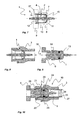
- Fig. 1 shows a adopted as known cap 30, which is pushed onto a plug-in element 6.
- the plug-in element 6 is sealed via its sealing element 24.
- the closure cap 30 forms a reservoir 31 in front of the conduit opening 16 of the plug element 6.
- Fig. 2 shows a known accepted plug 29 in a short can opening 3.
- Fig. 3 the same stopper 29 is shown in a long can opening 3.
- a sealing function is therefore not given.
- FIG. 4 an example of a closure element 1 is shown, wherein on the outer surface 2 by means of the sealing lip 7 in the first outer section 8, a plug is formed and with the inner surface 4, a receiving opening 5 for a plug-in element 6 (not shown) is formed.
- FIGS. 5 and 6 is the closure element 1 according to the Fig. 5 shown.
- those in the Fig. 4 designated components of the closure element 1 is not specified, but identical.
- Fig. 5 it can be seen that with the sealing lip 7 (see. Fig. 4 ) Can opening 3 can be sealed and at the same time the can opening 3 can be protected against contamination, without a double fit exists.
- Fig. 6 It is shown that the closure element 1 is also suitable for use as a cap for a plug-in element 6 and surrounds a received area 18 of the plug-in element 6.
- Fig. 7 an example of the closure element 1 is shown, which has a pin 15 and a rim portion 17.
- the plugging property of the closure element 1 is formed over the outer surface 2 and the capping property of the closure element 1 is formed over the inner surface 4, which surrounds a receiving opening 5.
- the sealing lip 7 is arranged in the first outer portion 8 and arranged slightly inclined inwardly in this example and directed angularly away from the conical surface of the first outer section 8.
- the first outer diameter 11 of the sealing lip 7 in the first section 8 is smaller than the second outer diameter 12 in the second section 9.
- the Einrast Scheme 20 see. Fig.
- the sealing lip 7 with the first outer diameter 11 is inserted into the can opening 3, without the spring element 21 (see. Fig. 10 ) to get in touch.
- the third outer portion 10 is continued by the sealing lip 7 and the first outer portion 8 is inclined at approximately 45 ° to the center.
- the pin 15 is extended in both directions, so that the closure element 1 can be easily removed by hand from the plug-in element 6 or the can opening 3.
- the flared edge portion 17 is shown, which serves to protect against contamination.
- FIGS. 8 and 9 show the closure element 1 according to the Fig. 7 , wherein also here for the sake of clarity, the reference numerals for identical components of the closure element 1 has been omitted.
- Fig. 8 shows the closure element 1 in the can opening 3, which is shown here in the long version. It can be seen that the closure element 1 slightly above the extended pin 15 (see. Fig. 7 ) can be pulled out by hand.
- Fig. 9 is the closure element 1 according to Fig. 7 pushed on a plug-in element 6 shown.
- the pin 15 and the edge portion 17 form a first contact surface 13 and a second contact surface 14 form.
- the pin 15 is inserted into the conduit opening 16 of the plug element 6.
- a hydraulic connection system 19 is shown in which the plug-in element 6 as in Fig. 9 , the can opening 3 as in Fig. 8 and the closure element 1 as in Fig. 7 are used and connected to each other so that they can not conduct fluid.
- the corresponding components form the groove 28 and the sealing area 23 with the sealing element 24 on the plug element 6.
- the first inner diameter 22 is set up in such a way that the closure element 1 can be passed with the first outer diameter 11, without coming into contact with the spring element 21.
- the closure element 1 has a second inner diameter 27, which is greater than the maximum outer diameter 25 of the sealing element 24 of the plug element 1.
- closure element With the closure element proposed here, it is possible to seal both a can opening and a plug-in element (at the same time) without being damaged in the process or damaging the plug-in element or the can opening. At the same time, the closure element is universally applicable and protects the can opening or the plug-in element from contamination.
- closure element 2 outer surface 3 can opening 4 palm 5 receiving opening 6 plug-in element 7 sealing lip 8th First exterior section 9 Second exterior section 10 Third outside section 11 First outer diameter 12 Second outer diameter 13 First contact area 14 Second contact surface 15 spigot 16 line opening 17 edge section 18 Recorded area 19 Hydraulic connection system 20 catch area 21 spring element 22 First inner diameter 23 sealing area 24 sealing element 25 Maximum outer diameter 26 reception area 27 Second inner diameter 28 groove 29 sealing plug 30 cap 31 reservoir
Landscapes
- Engineering & Computer Science (AREA)
- General Engineering & Computer Science (AREA)
- Mechanical Engineering (AREA)
- Pressure Vessels And Lids Thereof (AREA)
- Pipe Accessories (AREA)
Abstract
Description
- Die Erfindung betrifft ein Verschlusselement für ein hydraulisches Anschlusssystem, insbesondere für standardisierte Male- und Female-Anschlüsse bei Druckleitungen, hydraulischen Kupplungsnehmern und -gebern sowie bei Momentenspitzenbegrenzern (PTL = Peak Torque Limiter) und dergleichen.
- Aus dem Stand der Technik ist ein Verschlussstopfen bekannt, welcher in einen Female-Anschluss eingeführt werden kann und diesen dadurch abdichtet. Nachteilig ist bei diesem Verschlussstopfen, dass es unterschiedliche Standardlängen gibt und dieser Verschlussstopfen nur für eine bestimmte Standardlänge einsetzbar ist. Es ist auch bekannt, diesen Verschlussstopfen derart auszubilden, dass er zugleich als Verschlusskappe für einen Male-Anschluss verwendet werden kann. Dieser ist dabei derart eingerichtet, dass er das vorhandene Dichtelement des Male-Anschlusses zur Dichtung verwendet.
- Hiervon ausgehend liegt der vorliegenden Erfindung die Aufgabe zugrunde, die aus dem Stand der Technik bekannten Nachteile zumindest teilweise zu überwinden. Die Aufgabe wird durch die Merkmale der unabhängigen Patentansprüche gelöst. Vorteilhafte Weiterbildungen sind Gegenstand der abhängigen Patentansprüche.
- Die Erfindung betrifft ein Verschlusselement für ein hydraulisches Anschlusssystem, wobei das Verschlusselement eine Außenfläche und eine Innenfläche aufweist und wobei das Verschlusselement sowohl außenseitig als Stopfen für eine Dosenöffnung verwendbar ist als auch innenseitig als Kappe mit einer Aufnahmeöffnung für ein Steckelement verwendbar ist, wobei das Steckelement mit der Dosenöffnung hydraulisch leitend verbindbar ist, und wobei eine Dosenöffnung mittels einer Dichtlippe abdichtbar ist, wobei die Dichtlippe in einem ersten Außenabschnitt der Außenfläche angeordnet ist und relativ zum ersten Außenabschnitt unter einem Winkel weg gerichtet ist.
- Das Verschlusselement ist sowohl als Stopfen als auch als Kappe verwendbar. In der Verwendung als Stopfen wird das Verschlusselement mit einem Teil der Außenfläche mit der jeweiligen Dosenöffnung derart in Kontakt gebracht, dass diese hydraulisch geschlossen ist. Die Dosenöffnung ist dabei eine Öffnung, die einen, vorzugsweise genormten, Female-Anschluss eines hydraulischen Anschlusssystems darstellt. Zu dieser Dosenöffnung existiert ein korrespondierendes Steckelement, welches passend in die Dosenöffnung einführbar ist, als entsprechender, vorzugsweise genormter, Male-Anschluss, und somit zum Beispiel zwei Schläuche hydraulisch leitend miteinander verbunden werden können. Eine hydraulisch leitende Verbindung stellt in diesem Zusammenhang eine Verbindung eines Leitungssystems für ein Fluid dar, bei dem die Dosenöffnung und das Steckelement derart miteinander verbunden sind, dass ein Fluid, insbesondere unter hohem Druck, durch miteinander über die Dosenöffnung und das Steckelement verbundene Leitungen in einer Leitungsrichtung strömen kann, ohne dabei im Bereich der Dosenöffnung und des Steckelements in die Umgebung austreten zu können. Dazu weist das Steckelement im Anschlussbereich ein Dichtelement, zum Beispiel einen Dichtring aus einem Elastomer, auf. Das Steckelement weist weiterhin eine zentrale Leitungsöffnung auf, durch die ein Fluid in die Dosenöffnung oder aus der Dosenöffnung herausgeleitet werden kann.
- Weiterhin weist die Dosenöffnung in der Regel ein Federelement und das Steckelement eine korrespondierende Nut auf, wobei über das Federelement das Steckelement mit der korrespondierenden Nut axial gesichert wird. Insbesondere kann das Steckelement durch einfaches Einstecken und Einrasten in der Dosenöffnung hydraulisch leitend mit diesem verbunden werden. Sowohl die Dosenöffnung als auch das Steckelement sind in der Regel aus einem Metall gefertigt. Die Nut des Steckelements ist dabei in einem Einrastbereich vorgesehen und in einem im Vergleich zum Einrastbereich verjüngten Dichtbereich ist das Dichtelement ausgebildet, der von der Eintrittsöffnung der Leitungsöffnung des Steckelements gesehen vorne angeordnet ist. Die Dosenöffnung weist entsprechend (vorne) einen Einrastbereich mit einem Federelement auf und einen im Vergleich dazu verjüngten Aufnahmebereich (hinten) für den Dichtbereich des Steckelements. Im Stand der Technik weist der Verschlussstopfen an der Spitze eine konische Fläche auf, die dazu eingerichtet ist, an dem konischen Übergang von dem Einrastbereich zum Aufnahmebereich der Dosenöffnung anzuliegen und damit die Dosenöffnung abzudichten. Um dem Verschlussstopfen des Stands der Technik wieder aus der Dosenöffnung entfernen zu können, ist ein Rand vorgesehen, der eine maximale Einstecktiefe des Verschlussstopfens des Stands der Technik in eine Dosenöffnung begrenzt. Daher müssen für verschiedene Dosenöffnungen mit verschieden langen Einrastbereichen verschieden lange Verschlussstopfen verwendet werden. Das hier vorgeschlagene Verschlusselement weist an der Außenfläche einen ersten Außenabschnitt auf, in welchem eine Dichtlippe angeordnet ist. Diese Dichtlippe ist unter einem Winkel von dem ersten Außenabschnitt weg gerichtet. In einer bevorzugten Ausführungsform liegt der Winkel bei 90° zum erste Außenabschnitt und/oder ist in etwa senkrecht nach außen zur Innenwand der Dosenöffnung gerichtet. Insbesondere ist die Dichtlippe derart eingerichtet, dass sie im ersten Außenabschnitt die einzige Kontaktfläche mit der Dosenöffnung bildet. Mit dieser Konstruktion ist es möglich, eine Dosenöffnung mittels des Verschlusselements in Verwendung als Stopfen für jegliche Längen der Dosenöffnung zu verwenden. Zugleich ist das erfindungsgemäße Verschlusselement als Kappe für ein korrespondierendes Steckelement verwendbar. Dazu bildet es mit einem Teil der Innenfläche innenseitig eine Aufnahmeöffnung, in die das Steckelement, vorzugsweise mit dem Dichtungsbereich, mit dem Dichtelement in das Verschlusselement einführbar ist. Vorteilhaft ist hierbei, dass das Verschlusselement gleichzeitig zum Verschließen der Dosenöffnung und zum Verschließen des Steckelements verwendet werden kann, sodass zwar das Steckelement nicht vollständig in der Dosenöffnung versenkbar ist, aber zum Beispiel in einer Vormontage bereits eindeutig in die richtige Position gebracht und dort gehalten werden kann.
- Das Verschlusselement ist vorzugsweise aus einem (einzigen) Material und einstückig ausgebildet. Ganz besonders bevorzugt ist das Verschlusselement aus einem Kunststoff geformt, insbesondere durch Spritzguss. Das Material ist dabei bevorzugt aus einem Elastomer gewählt, sodass es zumindest im Bereich der Dichtlippe Eigenschaften aufweist, die zum Abdichten einer Dosenöffnung und/oder eines Steckelements, welche bevorzugt aus einem Metall gefertigt sind, geeignet ist.
- In einer weiteren vorteilhaften Ausführungsform weist das Verschlusselement einen zweiten Außenabschnitt auf, mit welchem die Dosenöffnung gegen Verschmutzen schützbar ist, und der zweite Außenabschnitt bevorzugt konzentrisch radial nach außen versetzt ist und über die Außenfläche anlegbar ist.
- Mit dem Verschlussstopfen des Stands der Technik konnte bisher nicht zugleich ein Schutz gegen Verschmutzen bereitgestellt werden. Der Rand des Verschlussstopfens, welcher hauptsächlich zum wieder Entfernen des Verschlussstopfens eingerichtet ist, konnte nicht zum Anliegen an der Dosenöffnung beziehungsweise dem Steckelement gebracht werden, weil sonst eine Doppelpassung aufgetreten wäre und die Dichtwirkung gefährdet gewesen wäre. Insbesondere bei einer Langzeitverwendung des aus dem Stand der Technik bekannten Verschlussstopfens konnte daher die Dosenöffnung verschmutzen und damit sogar die Dichtwirkung des Verschlusselements gefährdet werden. Insbesondere wurde der Schmutz beim Entfernen des Verschlussstopfens nicht wieder herausgeführt und somit in das hydraulische Anschlusssystem eingebracht. Dies wiederum kann zu Beschädigungen und Beeinträchtigungen des hydraulischen Anschlusssystems und/oder sogar des gesamten hydraulischen Systems führen, welches unter Umständen empfindliche Ventile, Druckmessinstrumente und dergleichen aufweist. Aufgrund der Verwendung einer Dichtlippe, welche unter einen Winkel vom ersten Außenabschnitt des Verschlusselements weggerichtet ist und sich daher an die Dosenöffnung anlegen kann, ohne zu einer Verformung des übrigen Verschlusselements zu führen, ist es nun erstmals möglich, einen zweiten Außenabschnitt vorzusehen, welcher durch Anliegen an der Dosenöffnung die Dosenöffnung vor Verschmutzten schützt. Insbesondere kann keine Doppelpassung auftreten. Besonders bevorzugt ist der zweite Außenabschnitt konzentrisch radial nach außen versetzt, sodass das Verschlusselement mit der Außenfläche im zweiten Außenabschnitt im eingesteckten Zustand an der Dosenöffnung anliegt. Ganz besonders bevorzugt ist dieser zweite Außenabschnitt in einem Bereich des Verschlusselements angeordnet, der beim eingesteckten Zustand in der Dosenöffnung vor dem Federelement im Einrastbereich angeordnet ist. Der erste Außenabschnitt ist dabei in Einsteckrichtung vorne am Verschlusselement angeordnet und der zweite Außenabschnitt hinten.
- In einer weiteren vorteilhaften Ausführungsform des Verschlusselements weist die Dichtlippe einen ersten Außendurchmesser und der zweite Außenabschnitt einen zweiten Außendurchmesser auf, wobei der erste Außendurchmesser kleiner als der zweite Außendurchmesser ist.
- Die Dichtlippe liegt mit dem ersten Außendurchmesser im eingesteckten Zustand an der Dosenöffnung an. Der zweite Außendurchmesser des zweiten Außenabschnitts liegt zum Schutz gegen Verschmutzen ebenfalls an der Dosenöffnung im eingesteckten Zustand an. Wie bereits oben erwähnt, weist die Dosenöffnung ein Federelement auf, welches im Einrastbereich der Dosenöffnung in den Innendurchmesser der Dosenöffnung hineinragt. Das Federelement ist dabei in der Regel als Ring aus Federstahl gebildet, welcher an einer oder mehreren Stellen mit einem oder mehreren Knicken in den Einrastbereich der Dosenöffnung hineinragt, sodass das Steckelement mit der entsprechenden Nut in der Dosenöffnung eingerastet werden kann. Daher liegt in dem Einrastbereich der Dosenöffnung ein unsymmetrischer Querschnitt vor, welcher vom Verschlusselement zumindest teilweise durchschritten werden muss. Es ist daher vorteilhaft, zu verhindern, dass die Dichtlippe beim Einführen des Verschlusselements in die Dosenöffnung mit dem Federelement der Dosenöffnung in Kontakt kommt beziehungsweise beim Einschieben des Verschlusselements auf die Dichtlippe eine zu große Kraft durch das Federelement auf die Dichtlippe ausgeübt wird. Daher wird hier die Lösung vorgeschlagen, die Dichtlippe derart einzurichten, dass sie in dem Bereich der gegenüber dem Einrastbereich verjüngt ist, in der Dosenöffnung zum Anliegen kommt und einen ersten Außendurchmesser aufweist, der geringer ist als der zweite Außendurchmesser des zweiten Außenabschnitts, welcher dazu eingerichtet ist, im Einrastbereich der Dosenöffnung anzuliegen. Das bedeutet insbesondere, dass der erste Außendurchmesser der Dichtlippe kleiner ist als ein minimaler (konzentrischer) Innendurchmesser der Dosenöffnung im Einrastbereich. Der zweite Außendurchmesser dagegen entspricht exakt dem Innendurchmesser im Einrastbereich der Dosenöffnung oder weist demgegenüber ein geringes Aufmaß zur Erzeugung einer Presspassung auf und ist nicht über das Federelement hinaus in die Dosenöffnung hineinschiebbar. Hierdurch kann auch verhindert werden, dass das Verschlusselement zu tief in die Dosenöffnung eingeschoben wird und nur umständlich oder zerstörend wieder entfernt werden könnte.
- In einer weiteren vorteilhaften Ausführungsform des Verschlusselements weist die Außenfläche einen sich an den ersten Außenabschnitt anschließenden konzentrischen dritten Außenabschnitt auf, wobei der erste Außenabschnitt sich zum dritten Außenabschnitt hin erweitert und die Dichtlippe sich in Verlängerung des dritten Außenabschnitts zum ersten Au-βenabschnitt hin konzentrisch, insbesondere parallel, erstreckt.
- Vorteilhafter Weise ist zum Einführen des Verschlusselements in die Dosenöffnung der erste Außenabschnitt konisch geformt, sodass er eine Fase aufweist, die das Einführen des Verschlusselements in eine Dosenöffnung erleichtert. An den ersten Außenabschnitt anschlie-βend ist ein konzentrischer dritter Außenabschnitt vorgesehen, welcher vorzugsweise zylindrisch und konzentrisch zur Dosenöffnung ausgerichtet ist. Die Dichtlippe, welche im ersten Außenabschnitt angeordnet ist, ist hierbei konzentrisch und in Verlängerung zum dritten Abschnitt ausgerichtet. Bevorzugt ist der dritte Außenabschnitt mit einem geringeren Außendurchmesser versehen als der zweite Außenabschnitt. Ganz besonders bevorzugt ist der Außendurchmesser des dritten Außenabschnitts kleiner als der minimale Innendurchmesser der Dosenöffnung im Einrastbereich. Die Dichtlippe, die im Wesentlichen in Einsteckrichtung nach vorne gerichtet ist, ist dazu eingerichtet, in dem Übergangsbereich von dem Einrastbereich in der Dosenöffnung zu dem Aufnahmebereich der Dosenöffnung, welcher sich verjüngt, anzuliegen. Hierzu kann die Dichtlippe insbesondere ein wenig nach innen geneigt sein, sodass die Dichtlippe beim Einführen in die Dosenöffnung nach innen gedrückt wird und nicht die Gefahr besteht, dass die Dichtlippe verkantet und/oder nicht richtig abdichtet. Bevorzugt ist die Dichtlippe unter 2° bis 10°, bevorzugt unter 5°, in Bezug auf die zylindrische dritte Außenfläche des dritten Außenabschnitts nach innen geneigt. Der erste Außenabschnitt ist demgegenüber bevorzugt um mindestens 10°, bevorzugt um 30° bis 45°, nach innen geneigt.
- In einer weiteren vorteilhaften Ausführungsform bildet das Verschlusselement einen konzentrischen Zapfen aus, welcher in eine Leitungsöffnung eines Steckelements derart einsteckbar ist, dass diese abgedichtet ist.
- Im Stand der Technik wurde das vorhandene Dichtelement des Steckelements im Dichtbereich zum Abdichten verwendet. Dieses Dichtelement, welches in der Regel aus einem Elastomer gebildet ist, ist aber dazu eingerichtet, eine metallische Fläche mit einer genormten Oberflächenrauigkeit abzudichten. Insbesondere bei der Verwendung eines Verschlusselements aus einem Kunststoff, welcher ebenfalls zum Abdichten geeignet ist, kann es beim Aufschieben des Verschlusselements über das Dichtelement des Steckelements zu Beschädigungen an dem Dichtelement und/oder dem Steckelement kommen. Um diesen Nachteil zu überwinden, ist im dem Verschlusselement ein konzentrischer Zapfen ausgebildet, welcher in die zentrale Öffnung, die Leitungsöffnung, des Steckelements eingeführt werden kann. Dadurch wird das Steckelement abgedichtet. Ein weiterer Vorteil dieser Konstruktion des Verschlusselements ist, dass das Verschlusselement kein Reservoir bildet, in welchem sich das zu leitende Fluid sammeln kann. Darüber hinaus kann der Zapfen derart ausgebildet sein, dass er aus der Aufnahmeöffnung des Verschlusselements hinausragt, und darüber aus einer Dosenöffnung herausgezogen werden kann. Damit wird ein gewinkelter Rand zum Herausnehmen des Verschlusselements überflüssig und das Verschlusselement kann in verschieden tiefe Dosenöffnungen eingeführt werden, weil kein Anschlag mit der Dosenöffnung gebildet ist. Weiterhin kann der Zapfen auch über den ersten Außenabschnitt des Verschlusselements außenseitig hinausragen, sodass das Verschlusselement von dem Steckelement abgezogen werden kann, ohne das Verschlusselement an das Steckelement anzudrücken. Für diesen Zweck können die jeweiligen Zapfenenden rau und/oder geriffelt ausgeführt sein, sodass das Verschlusselement aus der Dosenöffnung oder dem Steckelement leicht von Hand entfernt werden kann.
- In einer weiteren vorteilhaften Ausführungsform bildet das Verschlusselement an der Aufnahmeöffnung einen Randabschnitt aus, mit welchem ein aufgenommener Bereich eines Steckelements gegen Verschmutzen schützbar ist, wobei der Randabschnitt derart eingerichtet ist, dass der Randabschnitt sich zur Aufnahmeöffnung hin radial nach außen erweitert und über die Innenfläche an dem Steckelement anlegbar ist.
- Auch für das Steckelement ist es von Vorteil, dieses beziehungsweise die Dichtlippe des Verschlusselements vor Verschmutzen zu schützen. Hierzu eignet sich insbesondere die Erweiterung des Steckelements vom Dichtbereich zum Einrastbereich als Anlagefläche für den Randabschnitt der Aufnahmeöffnung des Verschlusselements. Dabei erweitert sich der Randabschnitt zur Aufnahmeöffnung hin radial nach außen, sodass das Verschlusselement zum einen leicht auf das Steckelement aufführbar ist und zum anderen bei einer ausreichend elastischen Ausgestaltung des Verschlusselements beziehungsweise des Randabschnitts keine Doppelpassung entstehen kann. Vielmehr wird der Randabschnitt bis zur Anlage der Dichtfläche des Verschlusselements an dem Steckelement gegebenenfalls nach außen gedehnt.
- In einer weiteren vorteilhaften Ausführungsform des Verschlusselements bildet die Innenfläche allein mit dem Randabschnitt und/oder dem Zapfen eine Kontaktfläche für ein Steckelement und insbesondere die übrige Innenfläche bei einem Aufschieben zu keinem Zeitpunkt Kontakt mit dem Steckelement hat.
- Wie bereits oben erwähnt, kann durch die Materialwahl des Verschlusselements das Aufschieben auf das Steckelement an dessen Dichtelement, zum Beispiel einen Dichtring, zu Beschädigungen des Dichtelements führen. Daher ist es vorteilhaft, den Innendurchmesser des Verschlusselements derart zu wählen, dass das Dichtelement nicht berührt werden muss. Dabei kann der Zapfen wiederum als Führungselement dienen, so dass das Verschlusselement bereits vor dem Aufschieben der Innenfläche des Verschlusselements auf das Steckelement relativ zum Steckelement über die Leitungsöffnung des Steckelements zu diesem zentriert ist. In dieser Ausführungsform ist dabei vorteilhafter Weise die Innenfläche in dem Aufnahmebereich für das Steckelement mit einem Innendurchmesser ausgeführt, der größer ist als ein maximaler Außendurchmesser des Dichtbereichs des Steckelements. Erst der Randabschnitt kommt mit der Erweiterung des Steckelements im Übergang von dem Dichtbereich zum Einrastbereich zum Anliegen an dem Steckelement.
- In einer weiteren vorteilhaften Ausführungsform ist das Verschlusselement allein über die Dichtelemente in einer Dosenöffnung beziehungsweise auf einem Steckelement positionierbar.
- Positionieren bedeutet hierbei insbesondere neben der Zentrierung das Sicherstellen der axialen Position des Verschlusselements in der Dosenöffnung beziehungsweise auf dem Steckelement. Über das Positionieren des Verschlusselements allein über die Dichtelemente, zum Beispiel die Dichtlippe und/oder den Zapfen, ist sichergestellt, dass keine Doppelpassung vorliegt und die Dichtelemente optimal an der Dosenöffnung beziehungsweise dem Steckelement anliegen, und diese damit abdichten. Zusätzliche Positionierungsmittel sind hierbei nicht notwendig.
- Gemäß einem weiteren Aspekt der Erfindung wird auch ein hydraulisches Anschlusssystem zum leitenden Verbinden für ein Fluid vorgeschlagen, welche eine Dosenöffnung und ein leitend verbindbares Steckelement aufweist, wobei ein Verschlusselement nach der vorliegenden Erfindung zum Dichten der Dosenöffnung und/oder des Steckelements verwendbar ist, wenn die Dosenöffnung beziehungsweise das Steckelement nicht miteinander leitend verbunden sind.
- Das hydraulische Anschlusssystem ist dazu eingerichtet, zwei Abschnitte eines Hydrauliksystems lösbar miteinander zu verbinden. Häufig ist es vorteilhaft, die Dosenöffnung und das verbindbare Steckelement zeitweise oder dauerhaft (gegeneinander) abzudichten. Hierzu ist das oben beschriebene Verschlusselement besonders geeignet. Hierbei kann die Dosenöffnung beziehungsweise das Steckelement nicht nur abgedichtet werden, sondern auch gegen Verschmutzen geschützt werden. Insbesondere ist ein und dasselbe Steckelement für verschiedene Dosenöffnungen und Steckelemente einsetzbar. Insbesondere kann das Verschlusselement gleichzeitig in die Dosenöffnung als Stopfen eingeführt werden und auf das Steckelement als Kappe aufgesetzt werden.
- In einer weiteren vorteilhaften Ausführungsform des hydraulischen Anschlusssystems weist die Dosenöffnung einen Einrastbereich mit einem Federelement mit einem minimalen Innendurchmesser auf, wobei der Außendurchmesser der Dichtlippe kleiner ist als der minimale Durchmesser des Federelements, und wobei insbesondere das Steckelement einen Dichtbereich mit einem Dichtelement mit einem maximalen Außendurchmesser aufweist und im Verschlusselement innenseitig ein Aufnahmebereich mit einem Innendurchmesser für das Steckelement vorgesehen ist, wobei der Innendurchmesser größer als der maximale Außendurchmesser des Dichtelement ist.
- Wie bereits oben beschrieben, ist es vorteilhaft, zu verhindern, dass die Dichtlippe des Verschlusselements mit dem Federelement in Kontakt kommt beziehungsweise von dem Federelement auf die Dichtlippe eine so große Kraft ausgeübt wird, dass die Dichtlippe potentiell beschädigt wird. Hierzu ist der Außendurchmesser der Dichtlippe kleiner als der minimale Durchmesser des Federelements. Vorteilhaft ist dabei weiterhin, dass der dritte Außenabschnitt des Verschlusselements ebenfalls kleiner als der minimale Durchmesser des Federelements ist, sodass das Verschlusselement leicht einschiebbar ist, keine Doppelpassung auftritt und zudem keine Deformation des Verschlusselements durch ein Anliegen des Federelements an dem dritten Außenabschnitt auftritt, welcher die Wirkung der Dichtlippe und/oder des zweiten Außenabschnitts zum Schutz gegen Verschmutzen beeinträchtigt. Insbesondere weist das hydraulische Anschlusssystem zudem ein Verschlusselement mit einem Aufnahmebereich mit einem Innendurchmesser auf, welcher größer ist als der maximale Außendurchmesser des Dichtelements des Steckelements. Hierdurch wird verhindert, dass das Dichtelement beim Aufschieben des Verschlusselements auf das Steckelement beschädigt wird.
- Die in den Patentansprüchen einzeln aufgeführten Merkmale sind in beliebiger, technologisch sinnvoller Weise miteinander kombinierbar und können durch erläuternde Sachverhalte aus der Beschreibung und Details aus den Figuren ergänzt werden, wobei weitere Ausführungsvarianten der Erfindung aufgezeigt werden.
- Die Erfindung sowie das technische Umfeld werden nachfolgend anhand der Figuren näher erläutert. Die Figuren zeigen besonders bevorzugte Ausführungsbeispiele, auf die die Erfindung jedoch nicht beschränkt ist. Insbesondere ist darauf hinzuweisen, dass die Figuren und insbesondere die dargestellten Größenverhältnisse nur schematisch sind. Es zeigen:
- Fig. 1:
- eine als bekannt angenommene Verschlusskappe auf einem Steckelement,
- Fig. 2:
- einen als bekannt angenommenen Verschlussstopfen in einer kurzen Dosenöffnung,
- Fig. 3:
- einen als bekannt angenommenen Verschlussstopfen in einer langen Dosenöffnung,
- Fig. 4:
- ein Beispiel eines Verschlusselements mit Dichtlippe,
- Fig. 5:
- ein Beispiel des Verschlusselements in einer langen Dosenöffnung,
- Fig. 6:
- ein Beispiel des Verschlusselements auf einem Steckelement,
- Fig. 7:
- ein Beispiel des Verschlusselements mit Zapfen und erweitertem Außendurchmesser,
- Fig. 8:
- ein Beispiel des Verschlusselements in einer langen Dosenöffnung,
- Fig. 9:
- ein Beispiel des Verschlusselements auf einem Steckelement, und
- Fig. 10:
- ein Beispiel eines zusammengesteckten hydraulischen Anschlusssystems.
-
Fig. 1 zeigt eine als bekannt angenommene Verschlusskappe 30, die auf ein Steckelement 6 aufgeschoben ist. Hierbei wird das Steckelement 6 über sein Dichtelement 24 abgedichtet. Es ist zu erkennen, dass die Verschlusskappe 30 ein Reservoir 31 vor der Leitungsöffnung 16. des Steckelements 6 bildet. -
Fig. 2 zeigt einen als bekannt angenommenen Verschlussstopfen 29 in einer kurzen Dosenöffnung 3. InFig. 3 ist der gleiche Verschlussstopfen 29 in einer langen Dosenöffnung 3 gezeigt. InFig. 3 ist eine Dichtfunktion daher nicht gegeben. - In
Fig. 4 ist ein Beispiel eines Verschlusselements 1 gezeigt, wobei an der Außenfläche 2 mittels der Dichtlippe 7 im ersten Außenabschnitt 8 ein Stopfen gebildet wird und mit der Innenfläche 4 eine Aufnahmeöffnung 5 für ein Steckelement 6 (nicht dargestellt) gebildet wird. - In den
Fig. 5 und 6 ist das Verschlusselement 1 gemäß derFig. 5 gezeigt. Der Übersichtlichkeit halber sind die in derFig. 4 bezeichneten Komponenten des Verschlusselements 1 nicht näher bezeichnet, aber identisch. InFig. 5 ist zu erkennen, dass mit der Dichtlippe 7 (vgl.Fig. 4 ) die Dosenöffnung 3 abgedichtet werden kann und dabei zugleich die Dosenöffnung 3 gegen Verschmutzen geschützt werden kann, ohne dass eine Doppelpassung vorliegt. InFig. 6 ist gezeigt, dass das Verschlusselement 1 auch für die Verwendung als Kappe für ein Steckelement 6 geeignet ist und einen aufgenommenen Bereich 18 des Steckelements 6 umgibt. - In
Fig. 7 ist ein Beispiel des Verschlusselements 1 gezeigt, welches über einen Zapfen 15 und einen Randabschnitt 17 verfügt. Auch hier ist die Stopfeneigenschaft des Verschlusselements 1 über die Außenfläche 2 gebildet und die Kappeneigenschaft des Verschlusselements 1 über die Innenfläche 4 gebildet, die eine Aufnahmeöffnung 5 umgibt. Die Dichtlippe 7 ist im ersten Außenabschnitt 8 angeordnet und in diesem Beispiel leicht nach innen geneigt angeordnet und von der konischen Fläche des ersten Außenabschnitts 8 winklig weg gerichtet. Der erste Außendurchmesser 11 der Dichtlippe 7 im ersten Abschnitt 8 ist kleiner als der zweite Außendurchmesser 12 im zweiten Abschnitt 9. Im zweiten Abschnitt 9 ist ein Anliegen mit dem Einrastbereich 20 (vgl.Fig. 10 ) möglich, während die Dichtlippe 7 mit dem ersten Außendurchmesser 11 in die Dosenöffnung 3 einführbar ist, ohne mit dem Federelement 21 (vgl.Fig. 10 ) in Kontakt zu kommen. Der dritte Außenabschnitt 10 wird von der Dichtlippe 7 fortgesetzt und der erste Außenabschnitt 8 neigt sich um etwa 45° konisch zur Mitte. In diesem Beispiel ist der Zapfen 15 in beide Richtungen verlängert, sodass das Verschlusselement 1 leicht von Hand von dem Steckelement 6 oder der Dosenöffnung 3 abgezogen werden kann. Ebenfalls ist der konisch erweiterte Randabschnitt 17 gezeigt, der zum Schutz gegen Verschmutzen dient. - Die
Figuren 8 und 9 zeigen das Verschlusselement 1 gemäß derFig. 7 , wobei hier ebenfalls der Übersichtlichkeit halber auf die Bezugszeichen für identische Komponenten des Verschlusselements 1 verzichtet wurde.Fig. 8 zeigt das Verschlusselement 1 in der Dosenöffnung 3, die hier in der langen Version gezeigt ist. Es ist zu erkennen, dass das Verschlusselement 1 leicht über den verlängerten Zapfen 15 (vgl.Fig. 7 ) von Hand herausgezogen werden kann. InFig. 9 ist das Verschlusselement 1 gemäßFig. 7 aufgeschoben auf ein Steckelement 6 gezeigt. Hierbei bilden nur der Zapfen 15 und der Randabschnitt 17 eine erste Kontaktfläche 13 und eine zweite Kontaktfläche 14 bilden. Der Zapfen 15 ist in die Leitungsöffnung 16 des Steckelements 6 eingeführt. - In der
Fig. 10 ist ein hydraulisches Anschlusssystem 19 gezeigt, bei dem das Steckelement 6 wie inFig. 9 , die Dosenöffnung 3 wie inFig. 8 und das Verschlusselement 1 wie inFig. 7 verwendet sind und miteinander derart verbunden sind, dass sie kein Fluid leiten können. Zu erkennen sind hier der Einrastbereich 20 mit dem Federelement 21 und der Aufnahmebereich 26 der Dosenöffnung 3. Die korrespondierenden Komponenten bilden die Nut 28 und der Dichtbereich 23 mit dem Dichtelement 24 am Steckelement 6. Der erste Innendurchmesser 22 ist derart eingerichtet, dass das Verschlusselement 1 mit dem ersten Außendurchmesser 11 hindurchgeführt werden kann, ohne mit dem Federelement 21 in Kontakt zu kommen. In seiner Kappeneigenschaft innenseitig weist das Verschlusselement 1 einen zweiten Innendurchmesser 27 auf, der größer als der maximale Außendurchmesser 25 des Dichtelements 24 des Steckelements 1 ist. - Mit dem hier vorgeschlagenen Verschlusselement ist es möglich, sowohl eine Dosenöffnung als auch ein Steckelement (gleichzeitig) abzudichten, ohne dabei selbst beschädigt zu werden beziehungsweise das Steckelement oder die Dosenöffnung zu beschädigen. Zugleich ist das Verschlusselement universell einsetzbar und schützt die Dosenöffnung beziehungsweise das Steckelement vor Verschmutzen.
Bezugszeichenliste 1 Verschlusselement 2 Außenfläche 3 Dosenöffnung 4 Innenfläche 5 Aufnahmeöffnung 6 Steckelement 7 Dichtlippe 8 Erster Außenabschnitt 9 Zweiter Außenabschnitt 10 Dritter Außenabschnitt 11 Erster Außendurchmesser 12 Zweiter Außendurchmesser 13 Erste Kontaktfläche 14 Zweite Kontaktfläche 15 Zapfen 16 Leitungsöffnung 17 Randabschnitt 18 Aufgenommener Bereich 19 Hydraulisches Anschlusssystem 20 Einrastbereich 21 Federelement 22 Erster Innendurchmesser 23 Dichtbereich 24 Dichtelement 25 Maximaler Außendurchmesser 26 Aufnahmebereich 27 Zweiter Innendurchmesser 28 Nut 29 Verschlussstopfen 30 Verschlusskappe 31 Reservoir
Claims (10)
- Verschlusselement (1) für ein hydraulisches Anschlusssystem (21), wobei das Verschlusselement (1) eine Außenfläche (2) und einen Innenfläche (4) aufweist und wobei das Verschlusselement (1) sowohl außenseitig als Stopfen für eine Dosenöffnung (3) verwendbar ist als auch innenseitig als Kappe mit einer Aufnahmeöffnung (5) für ein Steckelement (6) verwendbar ist, wobei das Steckelement (6) mit der Dosenöffnung (3) hydraulisch leitend verbindbar ist, und wobei eine Dosenöffnung (3) mittels einer Dichtlippe (7) abdichtbar ist, wobei die Dichtlippe (7) in einem ersten Außenabschnitt (8) der Außenfläche (2) angeordnet ist und relativ zum ersten Außenabschnitt (8) unter einem Winkel weg gerichtet ist.
- Verschlusselement (1) nach Anspruch 1, wobei das Verschlusselement (1) einen zweiten Außenabschnitt (9) aufweist, mit welchem die Dosenöffnung (3) gegen Verschmutzen schützbar ist, und der zweite Außenabschnitt (9) bevorzugt konzentrisch radial nach außen versetzt ist und über die Außenfläche (2) anlegbar ist.
- Verschlusselement (1) nach Anspruch 2, wobei die Dichtlippe (7) einen ersten Außendurchmesser (11) und der zweite Außenabschnitt (9) einen zweiten Außendurchmesser (12) aufweist, wobei der erste Außendurchmesser (11) kleiner als der zweite Außendurchmesser (12) ist.
- Verschlusselement (1) nach einem der vorhergehenden Ansprüche, wobei die Außenfläche (2) einen sich an den ersten Außenabschnitt (8) anschließenden konzentrischen dritten Außenabschnitt (10) aufweist, wobei der erste Außenabschnitt (8) sich zum dritten Außenabschnitt (10) hin erweitert und die Dichtlippe (7) sich in Verlängerung des dritten Außenabschnitts (10) zum ersten Außenabschnitt (8) hin konzentrisch, insbesondere parallel, erstreckt.
- Verschlusselement (1) nach einem der vorhergehenden Ansprüche, wobei das Verschlusselement (1) einen konzentrischen Zapfen (15) ausbildet, welcher in eine Leitungsöffnung (16) eines Steckelements (6) derart einsteckbar ist, dass diese abgedichtet ist.
- Verschlusselement (1) nach einem der vorhergehenden Ansprüche, wobei das Verschlusselement (1) an der Aufnahmeöffnung (6) einen Randabschnitt (17) ausbildet, mit welchem ein aufgenommener Bereich (18) eines Steckelements (6) gegen Verschmutzen schützbar ist, wobei der Randabschnitt (17) derart eingerichtet ist, dass der Randabschnitt (17) sich zur Aufnahmeöffnung (5) hin radial nach außen erweitert und über die Innenfläche (4) an dem Steckelement (6) anlegbar ist.
- Verschlusselement (1) nach Anspruch 5 oder 6, wobei die Innenfläche (4) allein mit dem Randabschnitt (17) und/oder dem Zapfen (15) eine Kontaktfläche (19,20) für ein Steckelement (6) bildet, und insbesondere die übrige Innenfläche (4) bei einem Aufschieben zu keinem Zeitpunkt Kontakt mit dem Steckelement (6) hat.
- Verschlusselement (1) nach einem der vorhergehenden Ansprüche, wobei das Verschlusselement (1) allein über die Dichtelemente (7,15) in einer Dosenöffnung (3) bzw. auf einem Steckelement (6) positionierbar ist.
- Hydraulisches Anschlusssystem (21) zum leitenden Verbinden für ein Fluid, aufweisend eine Dosenöffnung (3) und ein leitend verbindbares Steckelement (6), wobei ein Verschlusselement (1) nach einem vorhergehenden Ansprüche zum Dichten der Dosenöffnung (3) und/oder des Steckelements (6) verwendbar ist, wenn die Dosenöffnung (3) bzw. das Steckelement (6) nicht miteinander leitend verbunden sind.
- Hydraulisches Anschlusssystem (19) nach Anspruch 9, wobei die Dosenöffnung (3) einen Einrastbereich (20) mit einem Federelement (21) mit einem minimalen Innendurchmesser (22) aufweist, wobei der Außendurchmesser (11) der Dichtlippe (7) kleiner ist als der erste Innendurchmesser (22) des Federelements (21), und wobei insbesondere das Steckelement (6) einen Dichtbereich (23) mit einem Dichtelement (24) mit einem maximalen Außendurchmesser (25) aufweist und im Verschlusselement (1) innenseitig ein Aufnahmebereich (26) mit einem zweiten Innendurchmesser (27) für das Steckelement (6) vorgesehen ist, wobei der zweite Innendurchmesser (27) größer als der maximale Außendurchmesser (25) des Dichtelements (24) ist.
Applications Claiming Priority (1)
| Application Number | Priority Date | Filing Date | Title |
|---|---|---|---|
| DE102012206765 | 2012-04-25 |
Publications (3)
| Publication Number | Publication Date |
|---|---|
| EP2657586A2 true EP2657586A2 (de) | 2013-10-30 |
| EP2657586A3 EP2657586A3 (de) | 2017-08-02 |
| EP2657586B1 EP2657586B1 (de) | 2018-12-05 |
Family
ID=48183997
Family Applications (1)
| Application Number | Title | Priority Date | Filing Date |
|---|---|---|---|
| EP13001962.3A Not-in-force EP2657586B1 (de) | 2012-04-25 | 2013-04-15 | Verschlusselement für ein hydraulisches Anschlusssystem |
Country Status (2)
| Country | Link |
|---|---|
| EP (1) | EP2657586B1 (de) |
| DE (1) | DE102013206104A1 (de) |
Cited By (5)
| Publication number | Priority date | Publication date | Assignee | Title |
|---|---|---|---|---|
| DE102013223593A1 (de) * | 2013-11-19 | 2015-05-21 | Schaeffler Technologies AG & Co. KG | Verschlusskappe |
| CN107152583A (zh) * | 2017-05-24 | 2017-09-12 | 上海空间推进研究所 | 一种航天推进系统密封堵头 |
| CN110094434A (zh) * | 2018-01-30 | 2019-08-06 | 徕卡姆动力传动系统有限责任公司 | 峰值扭矩限制器 |
| EP2881642B1 (de) * | 2013-12-04 | 2019-09-18 | Schaeffler Technologies AG & Co. KG | Schutzkappe |
| CN111493021A (zh) * | 2020-03-17 | 2020-08-07 | 北京物资学院 | 一种用于物流运输中的保鲜装置 |
Families Citing this family (1)
| Publication number | Priority date | Publication date | Assignee | Title |
|---|---|---|---|---|
| DE102013021678B3 (de) | 2013-12-18 | 2015-02-05 | Hans Oetiker Ag Maschinen- Und Apparatefabrik | Verschlussstopfen für eine Schnellkupplung |
Family Cites Families (3)
| Publication number | Priority date | Publication date | Assignee | Title |
|---|---|---|---|---|
| US4046168A (en) * | 1974-09-30 | 1977-09-06 | Mm Plastic (Mfg) Company, Inc. | Closure plugs |
| US5224515A (en) * | 1992-01-30 | 1993-07-06 | Porex Technologies Corp. | Tube closure |
| DE19813931B4 (de) * | 1998-03-28 | 2006-06-29 | Fte Automotive Gmbh | Steckverschluß für Außen- und/oder Innenanschlüsse und Verfahren zu dessen Herstellung |
-
2013
- 2013-04-08 DE DE102013206104A patent/DE102013206104A1/de not_active Withdrawn
- 2013-04-15 EP EP13001962.3A patent/EP2657586B1/de not_active Not-in-force
Non-Patent Citations (1)
| Title |
|---|
| None |
Cited By (6)
| Publication number | Priority date | Publication date | Assignee | Title |
|---|---|---|---|---|
| DE102013223593A1 (de) * | 2013-11-19 | 2015-05-21 | Schaeffler Technologies AG & Co. KG | Verschlusskappe |
| EP2881642B1 (de) * | 2013-12-04 | 2019-09-18 | Schaeffler Technologies AG & Co. KG | Schutzkappe |
| CN107152583A (zh) * | 2017-05-24 | 2017-09-12 | 上海空间推进研究所 | 一种航天推进系统密封堵头 |
| CN110094434A (zh) * | 2018-01-30 | 2019-08-06 | 徕卡姆动力传动系统有限责任公司 | 峰值扭矩限制器 |
| CN111493021A (zh) * | 2020-03-17 | 2020-08-07 | 北京物资学院 | 一种用于物流运输中的保鲜装置 |
| CN111493021B (zh) * | 2020-03-17 | 2021-08-24 | 北京物资学院 | 一种用于物流运输中的保鲜装置 |
Also Published As
| Publication number | Publication date |
|---|---|
| EP2657586A3 (de) | 2017-08-02 |
| DE102013206104A1 (de) | 2013-10-31 |
| EP2657586B1 (de) | 2018-12-05 |
Similar Documents
| Publication | Publication Date | Title |
|---|---|---|
| EP2657586B1 (de) | Verschlusselement für ein hydraulisches Anschlusssystem | |
| EP3377796B1 (de) | Kupplungselement für eine kupplung zur verbindung von druckmittelleitungen | |
| EP1540234B1 (de) | Adapter-zwischenring für ein einschraubteil eines fluid-stecksystems | |
| EP3198179A1 (de) | Verbindungsanordnung für ein wellrohr | |
| DE3113107A1 (de) | "abdichtvorrichtung" | |
| EP2479470A2 (de) | Steckkupplung für Druckmittel-Leitungen | |
| EP2192338B1 (de) | Anschlussstück | |
| DE102007022799B4 (de) | Vorrichtung zum Verbinden zweier Enden von Rohr- oder Schlauchleitungen | |
| AT507565B1 (de) | Anschlussvorrichtung für ein kunststoffrohr an einem anschlussnippel | |
| DE202015004351U1 (de) | Schneidring für eine Rohrverschraubung | |
| DE102008020833A1 (de) | Pressverbindung | |
| DE19623995A1 (de) | Steckkupplung für Druckmittelsysteme | |
| EP1770320B1 (de) | Lösbare Steckverbindung für Rohrleitungen | |
| AT518117B1 (de) | Anschlussvorrichtung | |
| DE602004002170T2 (de) | Abgedichtete Kupplungsvorrichtung für ein Rohr mit einem mit einem Gewinde versehenen Fortsatz | |
| DE2230740A1 (de) | Ringdichtung fuer verbindungen an rohrleitungen, armaturen und dergl | |
| EP2667074B1 (de) | System mit Klemmteil zur Steckverbindung von Rohren | |
| DE202008009398U1 (de) | Steckkupplung für Druckmittel-Leitungen | |
| DE20305482U1 (de) | Verschraubung zur abgedichteten Verbindung eines Rohres oder eines Schlauches mit einem Bauelement, insbesondere einem Anschluss- oder Kupplungsstück | |
| DE102013207478A1 (de) | Kabelverbinder mit Dichtung und Zugentlastung | |
| DE102014217410A1 (de) | Fluidleitende Verbindungsanordnung sowie Klemmring | |
| DE102015109689B4 (de) | Rohrverbindung | |
| EP1416211B1 (de) | Rohrverbindung | |
| DE202010000872U1 (de) | Vorrichtung zum Verbinden eines Rohres mit einem Anschlussstutzen eines Armaturenanschlusses oder Fittings | |
| DE102014109319A1 (de) | Kappe für eine Schnellverbinderkupplung |
Legal Events
| Date | Code | Title | Description |
|---|---|---|---|
| PUAI | Public reference made under article 153(3) epc to a published international application that has entered the european phase |
Free format text: ORIGINAL CODE: 0009012 |
|
| AK | Designated contracting states |
Kind code of ref document: A2 Designated state(s): AL AT BE BG CH CY CZ DE DK EE ES FI FR GB GR HR HU IE IS IT LI LT LU LV MC MK MT NL NO PL PT RO RS SE SI SK SM TR |
|
| AX | Request for extension of the european patent |
Extension state: BA ME |
|
| RAP1 | Party data changed (applicant data changed or rights of an application transferred) |
Owner name: SCHAEFFLER TECHNOLOGIES GMBH & CO. KG |
|
| RAP1 | Party data changed (applicant data changed or rights of an application transferred) |
Owner name: SCHAEFFLER TECHNOLOGIES AG & CO. KG |
|
| PUAL | Search report despatched |
Free format text: ORIGINAL CODE: 0009013 |
|
| AK | Designated contracting states |
Kind code of ref document: A3 Designated state(s): AL AT BE BG CH CY CZ DE DK EE ES FI FR GB GR HR HU IE IS IT LI LT LU LV MC MK MT NL NO PL PT RO RS SE SI SK SM TR |
|
| AX | Request for extension of the european patent |
Extension state: BA ME |
|
| RIC1 | Information provided on ipc code assigned before grant |
Ipc: F16L 55/11 20060101AFI20170628BHEP Ipc: F16L 55/115 20060101ALI20170628BHEP |
|
| STAA | Information on the status of an ep patent application or granted ep patent |
Free format text: STATUS: REQUEST FOR EXAMINATION WAS MADE |
|
| 17P | Request for examination filed |
Effective date: 20180202 |
|
| RBV | Designated contracting states (corrected) |
Designated state(s): AL AT BE BG CH CY CZ DE DK EE ES FI FR GB GR HR HU IE IS IT LI LT LU LV MC MK MT NL NO PL PT RO RS SE SI SK SM TR |
|
| GRAP | Despatch of communication of intention to grant a patent |
Free format text: ORIGINAL CODE: EPIDOSNIGR1 |
|
| STAA | Information on the status of an ep patent application or granted ep patent |
Free format text: STATUS: GRANT OF PATENT IS INTENDED |
|
| INTG | Intention to grant announced |
Effective date: 20180731 |
|
| GRAS | Grant fee paid |
Free format text: ORIGINAL CODE: EPIDOSNIGR3 |
|
| GRAA | (expected) grant |
Free format text: ORIGINAL CODE: 0009210 |
|
| GRAA | (expected) grant |
Free format text: ORIGINAL CODE: 0009210 |
|
| STAA | Information on the status of an ep patent application or granted ep patent |
Free format text: STATUS: THE PATENT HAS BEEN GRANTED |
|
| AK | Designated contracting states |
Kind code of ref document: B1 Designated state(s): AL AT BE BG CH CY CZ DE DK EE ES FI FR GB GR HR HU IE IS IT LI LT LU LV MC MK MT NL NO PL PT RO RS SE SI SK SM TR |
|
| REG | Reference to a national code |
Ref country code: GB Ref legal event code: FG4D Free format text: NOT ENGLISH |
|
| REG | Reference to a national code |
Ref country code: CH Ref legal event code: EP |
|
| REG | Reference to a national code |
Ref country code: AT Ref legal event code: REF Ref document number: 1073496 Country of ref document: AT Kind code of ref document: T Effective date: 20181215 |
|
| REG | Reference to a national code |
Ref country code: IE Ref legal event code: FG4D Free format text: LANGUAGE OF EP DOCUMENT: GERMAN |
|
| REG | Reference to a national code |
Ref country code: DE Ref legal event code: R096 Ref document number: 502013011740 Country of ref document: DE |
|
| REG | Reference to a national code |
Ref country code: NL Ref legal event code: MP Effective date: 20181205 |
|
| REG | Reference to a national code |
Ref country code: LT Ref legal event code: MG4D |
|
| PG25 | Lapsed in a contracting state [announced via postgrant information from national office to epo] |
Ref country code: ES Free format text: LAPSE BECAUSE OF FAILURE TO SUBMIT A TRANSLATION OF THE DESCRIPTION OR TO PAY THE FEE WITHIN THE PRESCRIBED TIME-LIMIT Effective date: 20181205 Ref country code: LV Free format text: LAPSE BECAUSE OF FAILURE TO SUBMIT A TRANSLATION OF THE DESCRIPTION OR TO PAY THE FEE WITHIN THE PRESCRIBED TIME-LIMIT Effective date: 20181205 Ref country code: HR Free format text: LAPSE BECAUSE OF FAILURE TO SUBMIT A TRANSLATION OF THE DESCRIPTION OR TO PAY THE FEE WITHIN THE PRESCRIBED TIME-LIMIT Effective date: 20181205 Ref country code: BG Free format text: LAPSE BECAUSE OF FAILURE TO SUBMIT A TRANSLATION OF THE DESCRIPTION OR TO PAY THE FEE WITHIN THE PRESCRIBED TIME-LIMIT Effective date: 20190305 Ref country code: NO Free format text: LAPSE BECAUSE OF FAILURE TO SUBMIT A TRANSLATION OF THE DESCRIPTION OR TO PAY THE FEE WITHIN THE PRESCRIBED TIME-LIMIT Effective date: 20190305 Ref country code: LT Free format text: LAPSE BECAUSE OF FAILURE TO SUBMIT A TRANSLATION OF THE DESCRIPTION OR TO PAY THE FEE WITHIN THE PRESCRIBED TIME-LIMIT Effective date: 20181205 Ref country code: FI Free format text: LAPSE BECAUSE OF FAILURE TO SUBMIT A TRANSLATION OF THE DESCRIPTION OR TO PAY THE FEE WITHIN THE PRESCRIBED TIME-LIMIT Effective date: 20181205 |
|
| PG25 | Lapsed in a contracting state [announced via postgrant information from national office to epo] |
Ref country code: SE Free format text: LAPSE BECAUSE OF FAILURE TO SUBMIT A TRANSLATION OF THE DESCRIPTION OR TO PAY THE FEE WITHIN THE PRESCRIBED TIME-LIMIT Effective date: 20181205 Ref country code: RS Free format text: LAPSE BECAUSE OF FAILURE TO SUBMIT A TRANSLATION OF THE DESCRIPTION OR TO PAY THE FEE WITHIN THE PRESCRIBED TIME-LIMIT Effective date: 20181205 Ref country code: GR Free format text: LAPSE BECAUSE OF FAILURE TO SUBMIT A TRANSLATION OF THE DESCRIPTION OR TO PAY THE FEE WITHIN THE PRESCRIBED TIME-LIMIT Effective date: 20190306 Ref country code: AL Free format text: LAPSE BECAUSE OF FAILURE TO SUBMIT A TRANSLATION OF THE DESCRIPTION OR TO PAY THE FEE WITHIN THE PRESCRIBED TIME-LIMIT Effective date: 20181205 |
|
| PG25 | Lapsed in a contracting state [announced via postgrant information from national office to epo] |
Ref country code: NL Free format text: LAPSE BECAUSE OF FAILURE TO SUBMIT A TRANSLATION OF THE DESCRIPTION OR TO PAY THE FEE WITHIN THE PRESCRIBED TIME-LIMIT Effective date: 20181205 |
|
| PG25 | Lapsed in a contracting state [announced via postgrant information from national office to epo] |
Ref country code: PT Free format text: LAPSE BECAUSE OF FAILURE TO SUBMIT A TRANSLATION OF THE DESCRIPTION OR TO PAY THE FEE WITHIN THE PRESCRIBED TIME-LIMIT Effective date: 20190405 Ref country code: CZ Free format text: LAPSE BECAUSE OF FAILURE TO SUBMIT A TRANSLATION OF THE DESCRIPTION OR TO PAY THE FEE WITHIN THE PRESCRIBED TIME-LIMIT Effective date: 20181205 Ref country code: IT Free format text: LAPSE BECAUSE OF FAILURE TO SUBMIT A TRANSLATION OF THE DESCRIPTION OR TO PAY THE FEE WITHIN THE PRESCRIBED TIME-LIMIT Effective date: 20181205 Ref country code: PL Free format text: LAPSE BECAUSE OF FAILURE TO SUBMIT A TRANSLATION OF THE DESCRIPTION OR TO PAY THE FEE WITHIN THE PRESCRIBED TIME-LIMIT Effective date: 20181205 |
|
| PG25 | Lapsed in a contracting state [announced via postgrant information from national office to epo] |
Ref country code: SK Free format text: LAPSE BECAUSE OF FAILURE TO SUBMIT A TRANSLATION OF THE DESCRIPTION OR TO PAY THE FEE WITHIN THE PRESCRIBED TIME-LIMIT Effective date: 20181205 Ref country code: IS Free format text: LAPSE BECAUSE OF FAILURE TO SUBMIT A TRANSLATION OF THE DESCRIPTION OR TO PAY THE FEE WITHIN THE PRESCRIBED TIME-LIMIT Effective date: 20190405 Ref country code: RO Free format text: LAPSE BECAUSE OF FAILURE TO SUBMIT A TRANSLATION OF THE DESCRIPTION OR TO PAY THE FEE WITHIN THE PRESCRIBED TIME-LIMIT Effective date: 20181205 Ref country code: EE Free format text: LAPSE BECAUSE OF FAILURE TO SUBMIT A TRANSLATION OF THE DESCRIPTION OR TO PAY THE FEE WITHIN THE PRESCRIBED TIME-LIMIT Effective date: 20181205 Ref country code: SM Free format text: LAPSE BECAUSE OF FAILURE TO SUBMIT A TRANSLATION OF THE DESCRIPTION OR TO PAY THE FEE WITHIN THE PRESCRIBED TIME-LIMIT Effective date: 20181205 |
|
| REG | Reference to a national code |
Ref country code: DE Ref legal event code: R097 Ref document number: 502013011740 Country of ref document: DE |
|
| PLBE | No opposition filed within time limit |
Free format text: ORIGINAL CODE: 0009261 |
|
| STAA | Information on the status of an ep patent application or granted ep patent |
Free format text: STATUS: NO OPPOSITION FILED WITHIN TIME LIMIT |
|
| PG25 | Lapsed in a contracting state [announced via postgrant information from national office to epo] |
Ref country code: SI Free format text: LAPSE BECAUSE OF FAILURE TO SUBMIT A TRANSLATION OF THE DESCRIPTION OR TO PAY THE FEE WITHIN THE PRESCRIBED TIME-LIMIT Effective date: 20181205 Ref country code: DK Free format text: LAPSE BECAUSE OF FAILURE TO SUBMIT A TRANSLATION OF THE DESCRIPTION OR TO PAY THE FEE WITHIN THE PRESCRIBED TIME-LIMIT Effective date: 20181205 |
|
| 26N | No opposition filed |
Effective date: 20190906 |
|
| REG | Reference to a national code |
Ref country code: CH Ref legal event code: PL |
|
| REG | Reference to a national code |
Ref country code: BE Ref legal event code: MM Effective date: 20190430 |
|
| GBPC | Gb: european patent ceased through non-payment of renewal fee |
Effective date: 20190415 |
|
| PG25 | Lapsed in a contracting state [announced via postgrant information from national office to epo] |
Ref country code: LU Free format text: LAPSE BECAUSE OF NON-PAYMENT OF DUE FEES Effective date: 20190415 Ref country code: MC Free format text: LAPSE BECAUSE OF FAILURE TO SUBMIT A TRANSLATION OF THE DESCRIPTION OR TO PAY THE FEE WITHIN THE PRESCRIBED TIME-LIMIT Effective date: 20181205 |
|
| PG25 | Lapsed in a contracting state [announced via postgrant information from national office to epo] |
Ref country code: LI Free format text: LAPSE BECAUSE OF NON-PAYMENT OF DUE FEES Effective date: 20190430 Ref country code: GB Free format text: LAPSE BECAUSE OF NON-PAYMENT OF DUE FEES Effective date: 20190415 Ref country code: CH Free format text: LAPSE BECAUSE OF NON-PAYMENT OF DUE FEES Effective date: 20190430 |
|
| PG25 | Lapsed in a contracting state [announced via postgrant information from national office to epo] |
Ref country code: BE Free format text: LAPSE BECAUSE OF NON-PAYMENT OF DUE FEES Effective date: 20190430 |
|
| PG25 | Lapsed in a contracting state [announced via postgrant information from national office to epo] |
Ref country code: TR Free format text: LAPSE BECAUSE OF FAILURE TO SUBMIT A TRANSLATION OF THE DESCRIPTION OR TO PAY THE FEE WITHIN THE PRESCRIBED TIME-LIMIT Effective date: 20181205 |
|
| PG25 | Lapsed in a contracting state [announced via postgrant information from national office to epo] |
Ref country code: IE Free format text: LAPSE BECAUSE OF NON-PAYMENT OF DUE FEES Effective date: 20190415 |
|
| REG | Reference to a national code |
Ref country code: AT Ref legal event code: MM01 Ref document number: 1073496 Country of ref document: AT Kind code of ref document: T Effective date: 20190415 |
|
| PG25 | Lapsed in a contracting state [announced via postgrant information from national office to epo] |
Ref country code: AT Free format text: LAPSE BECAUSE OF NON-PAYMENT OF DUE FEES Effective date: 20190415 |
|
| PG25 | Lapsed in a contracting state [announced via postgrant information from national office to epo] |
Ref country code: CY Free format text: LAPSE BECAUSE OF FAILURE TO SUBMIT A TRANSLATION OF THE DESCRIPTION OR TO PAY THE FEE WITHIN THE PRESCRIBED TIME-LIMIT Effective date: 20181205 |
|
| PG25 | Lapsed in a contracting state [announced via postgrant information from national office to epo] |
Ref country code: MT Free format text: LAPSE BECAUSE OF FAILURE TO SUBMIT A TRANSLATION OF THE DESCRIPTION OR TO PAY THE FEE WITHIN THE PRESCRIBED TIME-LIMIT Effective date: 20181205 Ref country code: HU Free format text: LAPSE BECAUSE OF FAILURE TO SUBMIT A TRANSLATION OF THE DESCRIPTION OR TO PAY THE FEE WITHIN THE PRESCRIBED TIME-LIMIT; INVALID AB INITIO Effective date: 20130415 |
|
| PGFP | Annual fee paid to national office [announced via postgrant information from national office to epo] |
Ref country code: DE Payment date: 20210618 Year of fee payment: 9 Ref country code: FR Payment date: 20210423 Year of fee payment: 9 |
|
| PG25 | Lapsed in a contracting state [announced via postgrant information from national office to epo] |
Ref country code: MK Free format text: LAPSE BECAUSE OF FAILURE TO SUBMIT A TRANSLATION OF THE DESCRIPTION OR TO PAY THE FEE WITHIN THE PRESCRIBED TIME-LIMIT Effective date: 20181205 |
|
| REG | Reference to a national code |
Ref country code: DE Ref legal event code: R119 Ref document number: 502013011740 Country of ref document: DE |
|
| PG25 | Lapsed in a contracting state [announced via postgrant information from national office to epo] |
Ref country code: FR Free format text: LAPSE BECAUSE OF NON-PAYMENT OF DUE FEES Effective date: 20220430 Ref country code: DE Free format text: LAPSE BECAUSE OF NON-PAYMENT OF DUE FEES Effective date: 20221103 |
|
| P01 | Opt-out of the competence of the unified patent court (upc) registered |
Effective date: 20230523 |