EP2881642B2 - Couvercle de protection - Google Patents
Couvercle de protection Download PDFInfo
- Publication number
- EP2881642B2 EP2881642B2 EP14193204.6A EP14193204A EP2881642B2 EP 2881642 B2 EP2881642 B2 EP 2881642B2 EP 14193204 A EP14193204 A EP 14193204A EP 2881642 B2 EP2881642 B2 EP 2881642B2
- Authority
- EP
- European Patent Office
- Prior art keywords
- protective cap
- region
- stem
- diameter
- disengagement device
- Prior art date
- Legal status (The legal status is an assumption and is not a legal conclusion. Google has not performed a legal analysis and makes no representation as to the accuracy of the status listed.)
- Active
Links
- 230000001681 protective effect Effects 0.000 claims description 57
- 239000000463 material Substances 0.000 claims description 9
- 229920003023 plastic Polymers 0.000 claims description 7
- 239000004033 plastic Substances 0.000 claims description 7
- 238000007789 sealing Methods 0.000 claims description 6
- 230000004323 axial length Effects 0.000 claims description 5
- 238000009434 installation Methods 0.000 description 9
- 230000008878 coupling Effects 0.000 description 7
- 238000010168 coupling process Methods 0.000 description 7
- 238000005859 coupling reaction Methods 0.000 description 7
- 238000011109 contamination Methods 0.000 description 2
- 239000013013 elastic material Substances 0.000 description 2
- 239000012530 fluid Substances 0.000 description 2
- 238000004519 manufacturing process Methods 0.000 description 2
- 239000002245 particle Substances 0.000 description 2
- 230000007423 decrease Effects 0.000 description 1
- 229920002457 flexible plastic Polymers 0.000 description 1
- 238000011084 recovery Methods 0.000 description 1
- 238000000926 separation method Methods 0.000 description 1
Images
Classifications
-
- F—MECHANICAL ENGINEERING; LIGHTING; HEATING; WEAPONS; BLASTING
- F16—ENGINEERING ELEMENTS AND UNITS; GENERAL MEASURES FOR PRODUCING AND MAINTAINING EFFECTIVE FUNCTIONING OF MACHINES OR INSTALLATIONS; THERMAL INSULATION IN GENERAL
- F16L—PIPES; JOINTS OR FITTINGS FOR PIPES; SUPPORTS FOR PIPES, CABLES OR PROTECTIVE TUBING; MEANS FOR THERMAL INSULATION IN GENERAL
- F16L55/00—Devices or appurtenances for use in, or in connection with, pipes or pipe systems
- F16L55/10—Means for stopping flow from or in pipes or hoses
- F16L55/115—Caps
-
- F—MECHANICAL ENGINEERING; LIGHTING; HEATING; WEAPONS; BLASTING
- F16—ENGINEERING ELEMENTS AND UNITS; GENERAL MEASURES FOR PRODUCING AND MAINTAINING EFFECTIVE FUNCTIONING OF MACHINES OR INSTALLATIONS; THERMAL INSULATION IN GENERAL
- F16L—PIPES; JOINTS OR FITTINGS FOR PIPES; SUPPORTS FOR PIPES, CABLES OR PROTECTIVE TUBING; MEANS FOR THERMAL INSULATION IN GENERAL
- F16L2201/00—Special arrangements for pipe couplings
- F16L2201/80—Dust covers
Definitions
- the invention relates to a hydraulic release device for a friction clutch of a motor vehicle with a protective cap for a fluid-conducting connection port, in particular a release device used in a clutch bell, wherein the protective cap has at least one fastening region cooperating with the connection port.
- the publication DE 197 16 473 C2 shows such a hydraulic release device in the form of a central release mechanism for a friction clutch.
- protective caps are placed on the connection ports of the hydraulic system - usually with a force fit.
- the protective caps prevent fluid from escaping and dirt particles from entering the system.
- the protective cap is removed from the connection port in order to connect it to a further line, for example.
- the protective cap must be removed in a controlled manner immediately before assembly or connection of the connection port to the system.
- Such a dirt cap is described in the publication EP 2 657 586 A2 described, whereby the dirt cap has a type of plug that is pushed into a hydraulic line or connector, as well as a cap that is positioned radially outside the line or connector. In hard-to-reach places, access to the protective caps is often not possible.
- the EN 10 2010 043 438 A1 describes, for example, a protective cap for a fluid-carrying connection of a hydraulic system, which, in addition to a relatively weak force-fitting connection to ensure the necessary tightness, also provides a detachable form-fitting connection between a fastening area of the protective cap and the connection connection.
- a section of the fastening area is designed as at least one thread.
- the protective cap which is designed by means of a thread to be screwed on during assembly and off the connection closure during disassembly, takes up little space. However, it cannot be used in very limited radial installation space, such as in a clutch bell of a friction clutch in a motor vehicle. Here, there is too little space in the radial direction for manual or mechanical access to the protective cap in order to screw it onto the connection connection or unscrew it during disassembly.
- the object of the invention is therefore to provide a hydraulic release device for a friction clutch of a motor vehicle with a protective cap for a fluid-conducting connection port, in particular a hydraulically operated release device inserted in a clutch bell, which enables easy assembly/disassembly in the smallest of spaces and ensures good sealing at least against low pressures.
- a protective cap for a fluid-conducting connection connection, the protective cap having at least one fastening area that interacts with the connection connection, the fastening area being adjoined on the side facing away from the connection connection by an elastically bendable, resilient grip area that can be folded sideways in a resilient manner when there is mechanical resistance and can be raised to its starting position when the resistance is removed, and the grip area, which consists of a shaft adjoining the fastening area in the direction of a longitudinal axis and a head piece formed at the end of the shaft, can be resiliently tilted by a tilt angle in relation to the longitudinal axis and the shaft has a diameter that is greatly reduced compared to the diameter of the fastening area.
- At least the shaft is made of an elastic plastic material.
- the axial length of the grip area is preferably several times larger than the diameter of the shaft.
- the headpiece has a diameter formed by an extension of the shaft.
- the fastening region has means for sealing on its side facing the connection port.
- the protective cap is rotationally symmetrical.
- the fastening area and the grip area are made in one piece from an elastic Plastic material.
- the fastening area and the handle area can also be made of different materials.
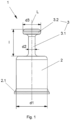
- a protective cap 1 is shown in a schematic representation.
- the protective cap 1 can be used, for example, in a clutch bell K of a friction clutch of a motor vehicle and serves to seal off a fluid-carrying connection port V of a release device during transport and/or assembly/dismantling.
- This application area of the protective cap 1 is in Fig. 2 and Fig. 3
- the application of the protective cap 1 is not limited to the area described.
- the protective cap 1 is preferably a rotationally symmetrical component made of an elastic plastic, which consists of a pot-shaped fastening area 2 and a handle area 3.
- the handle area 3 comprises a shaft 3.1 and a head piece 3.2, wherein the shaft 3.1 extending in the direction of a longitudinal axis L creates a connection between the fastening area 2 and the head piece 3.2.
- the shaft 3.1 which is formed by a strong reduction in diameter compared to the fastening area 2, which has a diameter d1, has a relatively small diameter d2 in relation to an axial length l of the handle area 3.
- the head piece 3.2 which is preferably designed with a flattened front side, has a slightly larger diameter d3 compared to the shaft 3.1.
- the grip area 3 When using an elastic, resilient plastic material - at least for the shaft 3.1 - the grip area 3 with the geometry has a tilting ability about the longitudinal axis L in conjunction with an elastic recovery ability in the direction of the longitudinal axis L.
- the fastening area 2 has a circumferential flange 2.1 on its open side facing away from the handle area 3, the arrangement of which is given here as an example for the use of further means for sealing against at least low pressures which arise during transport and/or during assembly/dismantling at the connection connection V (see Fig.3 ).
- Such means are a sealing lip-shaped design of the flange 2.1.
- the flange 2.1 also facilitates mounting (putting over) the protective cap 1 on the connection port V.
- the diameter d1 of the fastening area 2, which is essentially cylindrical and preferably made of an elastic material, is selected such that it approximately corresponds to the diameter of the connection port V to be closed or is slightly larger.
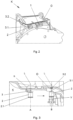
- the Fig.2 shows the use of the protective cap 1 in the coupling bell K.
- Two protective caps 1 are indicated here, which are attached to connection connections V (not shown here) and each protrude from an opening O in the coupling bell K.
- connection connections V not shown here
- the protective cap 1 In order to create a connection to a further line or a connection part (not shown) outside the coupling bell K, the protective cap 1 must be removed. This is easy to do because the geometry of the handle area 3 - with the narrow shaft 3.1 and the head piece 3.2 sitting on it - enables good handling, i.e. the head piece 3.2 can be easily gripped both manually and mechanically and the protective cap 1 can therefore be easily removed.
- Fig. 3 the protective cap 1 is shown during assembly of the release device in the clutch bell K.
- the complete release device (not shown here) with associated connection port V is inserted axially into the clutch bell K as a pre-assembled unit.
- the connection port V is located on a pressure line (not shown here in detail), which bridges a radial distance between the release device and the clutch bell K.
- the line or the connection port V must remain closed using the protective cap 1.
- the connection port V located in the clutch bell K must be closed again using the protective cap 1 to avoid contamination. This means that the connection port V with the protective cap 1 attached to it must be moved towards the opening O when assembling the system/release device when the radial installation space in the clutch bell K is very limited and must be moved away from the opening when disassembling.
- Fig.3 To explain the mode of operation of the protective cap 1, a movement of the connecting connection V in the coupling bell K from a position A to a position B is shown.
- the mounting direction is indicated by the arrow.
- the connection port V is not shown in position A.
- the connecting port V with the protective cap 1 In position B, the connecting port V with the protective cap 1 is in an end position associated with the opening O of the clutch bell K, in which end position the protective cap 1 can be removed from the connecting port V and this can be connected to the connecting part (not shown here) arranged outside the clutch bell K.
- the protective cap 1 located on the connection V must be moved along a coupling bell wall representing the radial installation space limitation, which is located at a distance from the fastening area 2 of the protective cap 1 that is smaller than the axial length l of the handle area 3. Due to the elastic bendability of the handle area 3 of the protective cap 1, the shaft 3.1 with the head piece 3.2 bends laterally at least partially - depending on the distance to the coupling bell wall - in a spring-loaded manner as soon as the radial installation space limitation is present as a mechanical resistance or obstacle.
- the tilting angle ⁇ i.e. how far the handle area 3 tilts from the upright starting position directed in the direction of the longitudinal axis L into a lateral avoidance position, depends on the dimensions of the protective cap 1 and on the radial installation space (distance) in the clutch bell K. If, for example, there is more space for the protective cap 1, the handle area 3 only has to tilt to the side at a smaller tilting angle ⁇ than in a narrow installation space.
- the protective cap 1 When the protective cap 1 (with the connection V) continues to move in the direction of the arrow, the protective cap 1 reaches the position B opposite the opening O. This increases the radial installation space and the grip area 3 (shaft 3.1 with the head piece 3.2) can straighten up again in the direction of the longitudinal axis L due to its spring-elastic design.
- the protective cap 1 is now in the position shown in Fig.2 shown position, in which the head piece 3.2 looks out of the opening O and is therefore easy to handle or dismantle. This also applies vice versa to the separation of the system from the connection part located outside the coupling bell K, whereby the protective cap 1 must be put back on or mounted on the connection connection V.
- the design of the protective cap 1 - here in particular the head piece 3.2 - enables good handling during its manual or mechanical assembly.
- the design of the shaft 3.1 (in conjunction with the elastic material) enables it to be folded over and straightened up again in a springy manner.
- the strength-optimized design of the grip area 3 (shaft 3.1 and head piece 3.2) also allows disassembly forces to be better absorbed.
- the design of the protective cap 1 - here in particular the fastening area 2 - ensures that the line is well sealed against small pressures. Since the protective cap 1 is a rotationally symmetrical part, no assembly orientation is necessary, which makes assembly of the protective cap 1 easier.
- the protective cap is made in one piece from an elastic plastic material.
- the use of an elastically flexible plastic, but above all the design of the protective cap 1, in particular of the handle area 3, enable the handle area 3 to bend away from the longitudinal axis L with the slightest mechanical resistance or to automatically straighten up again when the resistance decreases.
Landscapes
- Engineering & Computer Science (AREA)
- General Engineering & Computer Science (AREA)
- Mechanical Engineering (AREA)
- Mechanical Operated Clutches (AREA)
Claims (7)
- Dispositif de désaccouplement hydraulique destiné à un embrayage à friction d'un véhicule automobile, caractérisé par un capuchon de protection (1) destiné à un raccord de liaison (V) de guidage de fluide qui comporte au moins une région de fixation (2) coopérant avec le raccord de liaison (V), une région de préhension élastique (3), pliable élastiquement, étant raccordée à la région de fixation (2) du côté opposé au raccord de liaison (V), laquelle région de préhension peut être déviée latéralement de manière élastique en présence d'une résistance mécanique et peut reprendre sa position initiale lorsque la résistance est supprimée, et la région de préhension (3) qui comprend un tige (3.1) se raccordant à la région de fixation (2) dans la direction d'un axe longitudinal (L) et une pièce de tête (3.2) formée à l'extrémité de la tige (3.1) pouvant être inclinée de manière élastique d'un angle d'inclinaison (α) par rapport à l'axe longitudinal (L) et la tige (3.1) ayant un diamètre (d2) fortement réduit par rapport au diamètre (d1) de la région de fixation (2) et la région de fixation (2) présentant sur son côté tourné vers le raccord de liaison (V) des moyens (2.1), qui servent à assurer l'étanchéité, les moyens comprenant une bride (2.1) périphérique en forme de lèvre d'étanchéité sur la région de fixation (2) sur son côté ouvert opposé à la région de préhension (3).
- Dispositif de désaccouplement hydraulique selon la revendication 1, caractérisé en ce qu'au moins la tige (3.1) est en une matière synthétique élastique.
- Dispositif de désaccouplement hydraulique selon la revendication 1 ou 2, caractérisé en ce qu'une longueur axiale (1) de la région de préhension (3) est supérieure d'un multiple au diamètre (d2) de la tige (3.1).
- Dispositif de désaccouplement hydraulique selon l'une des revendications 1 à 3, caractérisé en ce que la pièce de tête (3.2) a un diamètre (d3) formé par l'extension de diamètre de la tige (3.1).
- Dispositif de désaccouplement hydraulique selon l'une des revendications 1 à 4, caractérisé en ce que le capuchon de protection (1) est à symétrie de révolution.
- Dispositif de désaccouplement hydraulique selon l'une des revendications 1 à 5, caractérisé en ce que la région de fixation (2) et la région de préhension (3) sont en des matières différentes.
- Dispositif de désaccouplement hydraulique selon l'une des revendications 1 à 6, caractérisé en ce que la région de fixation (2) et la région de préhension (3) sont réalisées d'une seule pièce en une matière synthétique élastique.
Applications Claiming Priority (1)
| Application Number | Priority Date | Filing Date | Title |
|---|---|---|---|
| DE102013224918 | 2013-12-04 |
Publications (3)
| Publication Number | Publication Date |
|---|---|
| EP2881642A1 EP2881642A1 (fr) | 2015-06-10 |
| EP2881642B1 EP2881642B1 (fr) | 2019-09-18 |
| EP2881642B2 true EP2881642B2 (fr) | 2024-05-22 |
Family
ID=51893935
Family Applications (1)
| Application Number | Title | Priority Date | Filing Date |
|---|---|---|---|
| EP14193204.6A Active EP2881642B2 (fr) | 2013-12-04 | 2014-11-14 | Couvercle de protection |
Country Status (2)
| Country | Link |
|---|---|
| EP (1) | EP2881642B2 (fr) |
| DE (1) | DE102014223273A1 (fr) |
Families Citing this family (1)
| Publication number | Priority date | Publication date | Assignee | Title |
|---|---|---|---|---|
| DE102014220644A1 (de) | 2014-10-13 | 2016-04-14 | Schaeffler Technologies AG & Co. KG | Schutzkappe, insbesondere für einen Hydraulikanschluss, Demontagewerkzeug und Verfahren zur Demontage der Schutzkappe |
Family Cites Families (8)
| Publication number | Priority date | Publication date | Assignee | Title |
|---|---|---|---|---|
| US4046276A (en) * | 1976-07-14 | 1977-09-06 | Baxter Travenol Laboratories, Inc. | Port protector cap for a container |
| DE3571017D1 (en) * | 1984-11-13 | 1989-07-20 | Baxter Int | Port and elastic closure |
| US4779997A (en) * | 1987-04-27 | 1988-10-25 | Baxter Travenol Laboratories, Inc. | Closure for a port and closure assembly |
| US5385253A (en) * | 1992-09-02 | 1995-01-31 | Baxter International Inc. | Port closure |
| DE19716473C2 (de) * | 1997-04-19 | 2002-07-04 | Fte Automotive Gmbh | Zentralausrücker für eine hydraulische Kupplungsbetätigung |
| DE102007028783A1 (de) * | 2007-06-22 | 2008-12-24 | Veritas Ag | Verschlusselement |
| DE102010043438A1 (de) | 2010-11-05 | 2012-05-10 | Robert Bosch Gmbh | Schutzkappe für einen flüssigkeitsführenden Verbindungsanschluss eines hydraulischen Systems |
| DE102013206104A1 (de) * | 2012-04-25 | 2013-10-31 | Schaeffler Technologies AG & Co. KG | Verschlusselement für ein hydraulisches Anschlusssystem |
-
2014
- 2014-11-14 DE DE102014223273.2A patent/DE102014223273A1/de not_active Withdrawn
- 2014-11-14 EP EP14193204.6A patent/EP2881642B2/fr active Active
Also Published As
| Publication number | Publication date |
|---|---|
| DE102014223273A1 (de) | 2015-06-11 |
| EP2881642A1 (fr) | 2015-06-10 |
| EP2881642B1 (fr) | 2019-09-18 |
Similar Documents
| Publication | Publication Date | Title |
|---|---|---|
| DE102014112584A1 (de) | Ventilvorrichtung | |
| EP3004702B1 (fr) | Combination d'un boîtier et d'une soupape | |
| WO2008110235A1 (fr) | Raccord de câble comprenant une contre-enveloppe ou un écrou d'accouplement | |
| DE102005058161B4 (de) | Schnellverschluss für den Installationsbereich | |
| EP2881642B2 (fr) | Couvercle de protection | |
| EP2334968B1 (fr) | Accouplement à verrouillage | |
| EP3153755B1 (fr) | Bride compressible à assemblage contrôlé | |
| DE102015009421A1 (de) | Stellventil zum Einstellen einer Prozessfluidströmung einer prozesstechnischen Anlage | |
| EP2515021A2 (fr) | Agencement de filtre de réduction de pression doté d'une protection anti-fuites | |
| EP3168375B1 (fr) | Robinetterie murale | |
| DE102017215675A1 (de) | Verbindungsanordnung für Rohre | |
| WO2018127318A1 (fr) | Ensemble soupape | |
| EP2639487B1 (fr) | Raccord pour tubes avec bouchon | |
| EP3557108B9 (fr) | Dispositif de raccordement pour conduites de fluide | |
| DE102014220644A1 (de) | Schutzkappe, insbesondere für einen Hydraulikanschluss, Demontagewerkzeug und Verfahren zur Demontage der Schutzkappe | |
| EP2481856A1 (fr) | Unité de soupape de remplissage | |
| DE102015202747B4 (de) | Absperrarmatur mit Sensor | |
| DE102014119410B4 (de) | Anbohrarmatur und Verfahren zum Herstellen einer Verbindung zu einer medienführenden Leitung mittels einer solchen Anbohrarmatur | |
| EP2873629B1 (fr) | Récipient émaillé ou autre composant émaillé ayant des volumes intérieurs et des manchons de raccordement | |
| DE102010055430B4 (de) | Klappenventil sowie Dichtung für ein Klappenventil | |
| WO2009015819A2 (fr) | Compteur de consommation pour des liquides | |
| DE60109071T2 (de) | Verschlussvorrichtung zum Verschließen einer Öffnung | |
| EP3421856B1 (fr) | Raccord de tuyauterie | |
| DE102015214829A1 (de) | Ventileinsatz | |
| DE10305724B4 (de) | Heizkörperanschluss |
Legal Events
| Date | Code | Title | Description |
|---|---|---|---|
| PUAI | Public reference made under article 153(3) epc to a published international application that has entered the european phase |
Free format text: ORIGINAL CODE: 0009012 |
|
| 17P | Request for examination filed |
Effective date: 20141114 |
|
| AK | Designated contracting states |
Kind code of ref document: A1 Designated state(s): AL AT BE BG CH CY CZ DE DK EE ES FI FR GB GR HR HU IE IS IT LI LT LU LV MC MK MT NL NO PL PT RO RS SE SI SK SM TR |
|
| AX | Request for extension of the european patent |
Extension state: BA ME |
|
| R17P | Request for examination filed (corrected) |
Effective date: 20151210 |
|
| RBV | Designated contracting states (corrected) |
Designated state(s): AL AT BE BG CH CY CZ DE DK EE ES FI FR GB GR HR HU IE IS IT LI LT LU LV MC MK MT NL NO PL PT RO RS SE SI SK SM TR |
|
| STAA | Information on the status of an ep patent application or granted ep patent |
Free format text: STATUS: EXAMINATION IS IN PROGRESS |
|
| 17Q | First examination report despatched |
Effective date: 20180416 |
|
| GRAP | Despatch of communication of intention to grant a patent |
Free format text: ORIGINAL CODE: EPIDOSNIGR1 |
|
| STAA | Information on the status of an ep patent application or granted ep patent |
Free format text: STATUS: GRANT OF PATENT IS INTENDED |
|
| INTG | Intention to grant announced |
Effective date: 20190403 |
|
| GRAS | Grant fee paid |
Free format text: ORIGINAL CODE: EPIDOSNIGR3 |
|
| GRAA | (expected) grant |
Free format text: ORIGINAL CODE: 0009210 |
|
| STAA | Information on the status of an ep patent application or granted ep patent |
Free format text: STATUS: THE PATENT HAS BEEN GRANTED |
|
| AK | Designated contracting states |
Kind code of ref document: B1 Designated state(s): AL AT BE BG CH CY CZ DE DK EE ES FI FR GB GR HR HU IE IS IT LI LT LU LV MC MK MT NL NO PL PT RO RS SE SI SK SM TR |
|
| REG | Reference to a national code |
Ref country code: GB Ref legal event code: FG4D Free format text: NOT ENGLISH |
|
| REG | Reference to a national code |
Ref country code: CH Ref legal event code: EP |
|
| REG | Reference to a national code |
Ref country code: DE Ref legal event code: R096 Ref document number: 502014012660 Country of ref document: DE |
|
| REG | Reference to a national code |
Ref country code: AT Ref legal event code: REF Ref document number: 1181742 Country of ref document: AT Kind code of ref document: T Effective date: 20191015 |
|
| REG | Reference to a national code |
Ref country code: IE Ref legal event code: FG4D Free format text: LANGUAGE OF EP DOCUMENT: GERMAN |
|
| REG | Reference to a national code |
Ref country code: NL Ref legal event code: MP Effective date: 20190918 |
|
| PG25 | Lapsed in a contracting state [announced via postgrant information from national office to epo] |
Ref country code: SE Free format text: LAPSE BECAUSE OF FAILURE TO SUBMIT A TRANSLATION OF THE DESCRIPTION OR TO PAY THE FEE WITHIN THE PRESCRIBED TIME-LIMIT Effective date: 20190918 Ref country code: BG Free format text: LAPSE BECAUSE OF FAILURE TO SUBMIT A TRANSLATION OF THE DESCRIPTION OR TO PAY THE FEE WITHIN THE PRESCRIBED TIME-LIMIT Effective date: 20191218 Ref country code: LT Free format text: LAPSE BECAUSE OF FAILURE TO SUBMIT A TRANSLATION OF THE DESCRIPTION OR TO PAY THE FEE WITHIN THE PRESCRIBED TIME-LIMIT Effective date: 20190918 Ref country code: HR Free format text: LAPSE BECAUSE OF FAILURE TO SUBMIT A TRANSLATION OF THE DESCRIPTION OR TO PAY THE FEE WITHIN THE PRESCRIBED TIME-LIMIT Effective date: 20190918 Ref country code: FI Free format text: LAPSE BECAUSE OF FAILURE TO SUBMIT A TRANSLATION OF THE DESCRIPTION OR TO PAY THE FEE WITHIN THE PRESCRIBED TIME-LIMIT Effective date: 20190918 Ref country code: NO Free format text: LAPSE BECAUSE OF FAILURE TO SUBMIT A TRANSLATION OF THE DESCRIPTION OR TO PAY THE FEE WITHIN THE PRESCRIBED TIME-LIMIT Effective date: 20191218 |
|
| REG | Reference to a national code |
Ref country code: LT Ref legal event code: MG4D |
|
| PG25 | Lapsed in a contracting state [announced via postgrant information from national office to epo] |
Ref country code: GR Free format text: LAPSE BECAUSE OF FAILURE TO SUBMIT A TRANSLATION OF THE DESCRIPTION OR TO PAY THE FEE WITHIN THE PRESCRIBED TIME-LIMIT Effective date: 20191219 Ref country code: RS Free format text: LAPSE BECAUSE OF FAILURE TO SUBMIT A TRANSLATION OF THE DESCRIPTION OR TO PAY THE FEE WITHIN THE PRESCRIBED TIME-LIMIT Effective date: 20190918 Ref country code: LV Free format text: LAPSE BECAUSE OF FAILURE TO SUBMIT A TRANSLATION OF THE DESCRIPTION OR TO PAY THE FEE WITHIN THE PRESCRIBED TIME-LIMIT Effective date: 20190918 Ref country code: AL Free format text: LAPSE BECAUSE OF FAILURE TO SUBMIT A TRANSLATION OF THE DESCRIPTION OR TO PAY THE FEE WITHIN THE PRESCRIBED TIME-LIMIT Effective date: 20190918 |
|
| PG25 | Lapsed in a contracting state [announced via postgrant information from national office to epo] |
Ref country code: ES Free format text: LAPSE BECAUSE OF FAILURE TO SUBMIT A TRANSLATION OF THE DESCRIPTION OR TO PAY THE FEE WITHIN THE PRESCRIBED TIME-LIMIT Effective date: 20190918 Ref country code: NL Free format text: LAPSE BECAUSE OF FAILURE TO SUBMIT A TRANSLATION OF THE DESCRIPTION OR TO PAY THE FEE WITHIN THE PRESCRIBED TIME-LIMIT Effective date: 20190918 Ref country code: IT Free format text: LAPSE BECAUSE OF FAILURE TO SUBMIT A TRANSLATION OF THE DESCRIPTION OR TO PAY THE FEE WITHIN THE PRESCRIBED TIME-LIMIT Effective date: 20190918 Ref country code: RO Free format text: LAPSE BECAUSE OF FAILURE TO SUBMIT A TRANSLATION OF THE DESCRIPTION OR TO PAY THE FEE WITHIN THE PRESCRIBED TIME-LIMIT Effective date: 20190918 Ref country code: EE Free format text: LAPSE BECAUSE OF FAILURE TO SUBMIT A TRANSLATION OF THE DESCRIPTION OR TO PAY THE FEE WITHIN THE PRESCRIBED TIME-LIMIT Effective date: 20190918 Ref country code: PL Free format text: LAPSE BECAUSE OF FAILURE TO SUBMIT A TRANSLATION OF THE DESCRIPTION OR TO PAY THE FEE WITHIN THE PRESCRIBED TIME-LIMIT Effective date: 20190918 Ref country code: PT Free format text: LAPSE BECAUSE OF FAILURE TO SUBMIT A TRANSLATION OF THE DESCRIPTION OR TO PAY THE FEE WITHIN THE PRESCRIBED TIME-LIMIT Effective date: 20200120 |
|
| PG25 | Lapsed in a contracting state [announced via postgrant information from national office to epo] |
Ref country code: IS Free format text: LAPSE BECAUSE OF FAILURE TO SUBMIT A TRANSLATION OF THE DESCRIPTION OR TO PAY THE FEE WITHIN THE PRESCRIBED TIME-LIMIT Effective date: 20200224 Ref country code: SK Free format text: LAPSE BECAUSE OF FAILURE TO SUBMIT A TRANSLATION OF THE DESCRIPTION OR TO PAY THE FEE WITHIN THE PRESCRIBED TIME-LIMIT Effective date: 20190918 Ref country code: SM Free format text: LAPSE BECAUSE OF FAILURE TO SUBMIT A TRANSLATION OF THE DESCRIPTION OR TO PAY THE FEE WITHIN THE PRESCRIBED TIME-LIMIT Effective date: 20190918 Ref country code: CZ Free format text: LAPSE BECAUSE OF FAILURE TO SUBMIT A TRANSLATION OF THE DESCRIPTION OR TO PAY THE FEE WITHIN THE PRESCRIBED TIME-LIMIT Effective date: 20190918 |
|
| REG | Reference to a national code |
Ref country code: DE Ref legal event code: R026 Ref document number: 502014012660 Country of ref document: DE |
|
| PLBI | Opposition filed |
Free format text: ORIGINAL CODE: 0009260 |
|
| REG | Reference to a national code |
Ref country code: CH Ref legal event code: PL |
|
| PLAX | Notice of opposition and request to file observation + time limit sent |
Free format text: ORIGINAL CODE: EPIDOSNOBS2 |
|
| 26 | Opposition filed |
Opponent name: FTE AUTOMOTIVE GMBH Effective date: 20200617 |
|
| PG2D | Information on lapse in contracting state deleted |
Ref country code: IS |
|
| PG25 | Lapsed in a contracting state [announced via postgrant information from national office to epo] |
Ref country code: LI Free format text: LAPSE BECAUSE OF NON-PAYMENT OF DUE FEES Effective date: 20191130 Ref country code: LU Free format text: LAPSE BECAUSE OF NON-PAYMENT OF DUE FEES Effective date: 20191114 Ref country code: MC Free format text: LAPSE BECAUSE OF FAILURE TO SUBMIT A TRANSLATION OF THE DESCRIPTION OR TO PAY THE FEE WITHIN THE PRESCRIBED TIME-LIMIT Effective date: 20190918 Ref country code: DK Free format text: LAPSE BECAUSE OF FAILURE TO SUBMIT A TRANSLATION OF THE DESCRIPTION OR TO PAY THE FEE WITHIN THE PRESCRIBED TIME-LIMIT Effective date: 20190918 Ref country code: CH Free format text: LAPSE BECAUSE OF NON-PAYMENT OF DUE FEES Effective date: 20191130 Ref country code: IS Free format text: LAPSE BECAUSE OF FAILURE TO SUBMIT A TRANSLATION OF THE DESCRIPTION OR TO PAY THE FEE WITHIN THE PRESCRIBED TIME-LIMIT Effective date: 20200119 |
|
| REG | Reference to a national code |
Ref country code: BE Ref legal event code: MM Effective date: 20191130 |
|
| PG25 | Lapsed in a contracting state [announced via postgrant information from national office to epo] |
Ref country code: SI Free format text: LAPSE BECAUSE OF FAILURE TO SUBMIT A TRANSLATION OF THE DESCRIPTION OR TO PAY THE FEE WITHIN THE PRESCRIBED TIME-LIMIT Effective date: 20190918 |
|
| GBPC | Gb: european patent ceased through non-payment of renewal fee |
Effective date: 20191218 |
|
| PG25 | Lapsed in a contracting state [announced via postgrant information from national office to epo] |
Ref country code: FR Free format text: LAPSE BECAUSE OF NON-PAYMENT OF DUE FEES Effective date: 20191118 Ref country code: IE Free format text: LAPSE BECAUSE OF NON-PAYMENT OF DUE FEES Effective date: 20191114 Ref country code: GB Free format text: LAPSE BECAUSE OF NON-PAYMENT OF DUE FEES Effective date: 20191218 |
|
| PLBB | Reply of patent proprietor to notice(s) of opposition received |
Free format text: ORIGINAL CODE: EPIDOSNOBS3 |
|
| PG25 | Lapsed in a contracting state [announced via postgrant information from national office to epo] |
Ref country code: BE Free format text: LAPSE BECAUSE OF NON-PAYMENT OF DUE FEES Effective date: 20191130 |
|
| REG | Reference to a national code |
Ref country code: AT Ref legal event code: MM01 Ref document number: 1181742 Country of ref document: AT Kind code of ref document: T Effective date: 20191114 |
|
| PG25 | Lapsed in a contracting state [announced via postgrant information from national office to epo] |
Ref country code: AT Free format text: LAPSE BECAUSE OF NON-PAYMENT OF DUE FEES Effective date: 20191114 |
|
| PG25 | Lapsed in a contracting state [announced via postgrant information from national office to epo] |
Ref country code: CY Free format text: LAPSE BECAUSE OF FAILURE TO SUBMIT A TRANSLATION OF THE DESCRIPTION OR TO PAY THE FEE WITHIN THE PRESCRIBED TIME-LIMIT Effective date: 20190918 |
|
| PG25 | Lapsed in a contracting state [announced via postgrant information from national office to epo] |
Ref country code: HU Free format text: LAPSE BECAUSE OF FAILURE TO SUBMIT A TRANSLATION OF THE DESCRIPTION OR TO PAY THE FEE WITHIN THE PRESCRIBED TIME-LIMIT; INVALID AB INITIO Effective date: 20141114 Ref country code: MT Free format text: LAPSE BECAUSE OF FAILURE TO SUBMIT A TRANSLATION OF THE DESCRIPTION OR TO PAY THE FEE WITHIN THE PRESCRIBED TIME-LIMIT Effective date: 20190918 |
|
| PLAB | Opposition data, opponent's data or that of the opponent's representative modified |
Free format text: ORIGINAL CODE: 0009299OPPO |
|
| R26 | Opposition filed (corrected) |
Opponent name: FTE AUTOMOTIVE GMBH Effective date: 20200617 |
|
| PG25 | Lapsed in a contracting state [announced via postgrant information from national office to epo] |
Ref country code: TR Free format text: LAPSE BECAUSE OF FAILURE TO SUBMIT A TRANSLATION OF THE DESCRIPTION OR TO PAY THE FEE WITHIN THE PRESCRIBED TIME-LIMIT Effective date: 20190918 |
|
| PG25 | Lapsed in a contracting state [announced via postgrant information from national office to epo] |
Ref country code: MK Free format text: LAPSE BECAUSE OF FAILURE TO SUBMIT A TRANSLATION OF THE DESCRIPTION OR TO PAY THE FEE WITHIN THE PRESCRIBED TIME-LIMIT Effective date: 20190918 |
|
| PUAH | Patent maintained in amended form |
Free format text: ORIGINAL CODE: 0009272 |
|
| STAA | Information on the status of an ep patent application or granted ep patent |
Free format text: STATUS: PATENT MAINTAINED AS AMENDED |
|
| PGFP | Annual fee paid to national office [announced via postgrant information from national office to epo] |
Ref country code: DE Payment date: 20240119 Year of fee payment: 10 |
|
| 27A | Patent maintained in amended form |
Effective date: 20240522 |
|
| AK | Designated contracting states |
Kind code of ref document: B2 Designated state(s): AL AT BE BG CH CY CZ DE DK EE ES FI FR GB GR HR HU IE IS IT LI LT LU LV MC MK MT NL NO PL PT RO RS SE SI SK SM TR |
|
| REG | Reference to a national code |
Ref country code: DE Ref legal event code: R102 Ref document number: 502014012660 Country of ref document: DE |