EP2881360A1 - Device for treating a container in a drink filling assembly and method for cleaning said device - Google Patents
Device for treating a container in a drink filling assembly and method for cleaning said device Download PDFInfo
- Publication number
- EP2881360A1 EP2881360A1 EP14196300.9A EP14196300A EP2881360A1 EP 2881360 A1 EP2881360 A1 EP 2881360A1 EP 14196300 A EP14196300 A EP 14196300A EP 2881360 A1 EP2881360 A1 EP 2881360A1
- Authority
- EP
- European Patent Office
- Prior art keywords
- treatment
- closure
- cleaning
- container
- opening
- Prior art date
- Legal status (The legal status is an assumption and is not a legal conclusion. Google has not performed a legal analysis and makes no representation as to the accuracy of the status listed.)
- Ceased
Links
Images

Classifications
-
- B—PERFORMING OPERATIONS; TRANSPORTING
- B67—OPENING, CLOSING OR CLEANING BOTTLES, JARS OR SIMILAR CONTAINERS; LIQUID HANDLING
- B67C—CLEANING, FILLING WITH LIQUIDS OR SEMILIQUIDS, OR EMPTYING, OF BOTTLES, JARS, CANS, CASKS, BARRELS, OR SIMILAR CONTAINERS, NOT OTHERWISE PROVIDED FOR; FUNNELS
- B67C3/00—Bottling liquids or semiliquids; Filling jars or cans with liquids or semiliquids using bottling or like apparatus; Filling casks or barrels with liquids or semiliquids
- B67C3/001—Cleaning of filling devices
- B67C3/002—Cleaning of filling devices using cups or dummies to be placed under the filling heads
- B67C3/004—Cleaning of filling devices using cups or dummies to be placed under the filling heads permanently attached to the filling machine and movable between a rest and a working position
Definitions
- the present invention relates to a device for treating a container, preferably in a beverage filling plant, particularly preferably for filling a container with a filling product.
- the present invention further relates to a method for cleaning the apparatus for treating the containers.
- Such a treatment member may be, for example, a filling member having a treatment opening in the form of a filling opening through which a treatment fluid in the form of a filling product passes into the container.
- a treatment opening of the respective treatment member is present in the form of a corresponding flushing opening, through which a treatment fluid in the form of a flushing fluid enters the container to be treated.
- clean containers by introducing a cleaning fluid, wherein the corresponding treatment member is then provided in the form of a cleaning member having a treatment opening in the form of the outlet opening for the treatment fluid in the form of the cleaning fluid.
- the cleaning medium for cleaning the treatment member is introduced via a separate cleaning channel in the treatment member, and then withdrawn via the leading in the production operation, the treatment fluid channel in the treatment organ, so that here quasi a backward flushing of the treatment fluid leading channels in the treatment device is made possible. Again, the cleaning medium does not escape from the treatment opening.
- This type of cleaning in which the treatment opening of the treatment member for cleaning the treatment member is closed with a closure and the treatment fluid leading channels are flushed in the treatment member with a cleaning medium, without this exits the treatment opening is also called “cleaning in place” (CIP ) or “Sterilization in Place” (SIP), since the treatment organ need not be removed, disassembled or disassembled to carry out the cleaning.
- CIP cleaning in place
- SIP Secondary in Place
- the closure closing the treatment opening is usually designed in the form of a closure cap which seals the treatment opening of the treatment organ in a sealing manner.
- the closure or the closure cap by means of a pivoting device from a production position in which the treatment opening is released and the treatment member is used to treat the container in a cleaning position pivoted, in which the treatment opening is closed in a fluid-tight manner and a cleaning of the treatment member is performed.
- the pivoting device usually has a rotary shaft, which is connected via a boom with the corresponding cap. By means of a combined rotary-lifting movement of this rotary shaft, the cap is pivoted from the production position to the cleaning position and back to the production position.
- the rotary shaft carries out in addition to the pivoting movement of a lifting movement, by means of which the cap is raised and is pressed onto the treatment opening when the cap is in the cleaning position. Accordingly, a complex pivoting device is necessary to perform the combined rotary-stroke movement and thus to move the shutter from the production position to the cleaning position and back again.
- Such pivoting caps in the form of CIP caps with a rotary lifting device are for example from the DE 10 2009 033 557 A1 . DE 10 2010 027 623 A1 or the DE 10 2010 027 624 A1 known.
- a device for treating a container preferably in a beverage filling plant, particularly preferably for filling a container with a filling product, comprising a treatment member having a treatment opening for treating the container with a treatment fluid, a closure for closing the treatment opening for cleaning the treatment member, and a pivoting device for moving the closure of a treatment opening for the treatment of the container release production position proposed in a treatment opening closing cleaning position.
- the closure can be pivoted by the pivoting device in a plane which is stationary relative to the treatment element.
- the pivoting device pivots the closure from the production position into the cleaning position in a plane fixed relative to the treatment member, a complex trajectory for moving the closure and thus a complex mechanical design of the pivoting device can be dispensed with. Due to the pivoting in a stationary plane, the pivoting device must accordingly execute only one rotation about a pivot axis. Lifting or lowering movements of the closure are not necessary. Accordingly, the pivoting device can be formed by a simple rotary drive, for example an electric motor or a compressed air drive. It is therefore unnecessary to provide a complex control for raising or lowering the closure for sealing the treatment opening in the cleaning position.
- the pivoting device preferably pivots the closure as close as possible under the treatment opening, so that the stationary plane in which the closure is pivoted is designed so that a sealing of the treatment opening with the closure can be achieved.
- the closure has a membrane, which can be pressed in the cleaning position by applying a pressure medium for sealing against the treatment opening.
- the membrane is preferably acted upon with compressed air, cleaning medium or any other medium, such that in the cleaning position, a sealing closure of the treatment opening of the treatment member is achieved by the closure.
- the membrane has a reinforcement region, which preferably follows the outer contours of the treatment opening.
- the reinforcing region may, for example, be in the form of a plate-shaped reinforcement in the region of the membrane which is pressed against the treatment opening.
- the pivoting device pivots the closure about an axis of rotation, wherein the axis of rotation is preferably arranged on the pitch circle of a rotary container treatment machine and / or is arranged eccentrically to the rotational axis of a carousel of the rotary treatment machine.
- each treatment member is assigned its own pivoting device with closure directly, which is arranged correspondingly together with the treatment member on a pitch circle of a rotary container treatment machine.
- the closure of each treatment opening in a rotary container treatment machine can be adjusted so that an optimum sealing effect is achieved.
- the treatment member and the pivoting device can be controlled individually together with the closure or, in the case of maintenance or defect, removed modularly from the rotary container treatment machine and then exchanged modularly.
- a piston is provided in the closure instead of or in addition to the membrane, by means of which the closure closes the treatment opening.
- the piston may comprise either a seal or a correspondingly shaped part, which is complementary to the region of the treatment member surrounding the treatment opening, in order to achieve a corresponding sealing.
- the pivoting device preferably comprises a rotary shaft, which extends along the axis of rotation, and by means of which the closure can be pivoted from the production position into the cleaning position.
- the rotary shaft to a pressure medium channel to Actuation of the membrane and / or the piston of the closure with a pressure medium, preferably with cleaning medium or compressed air on.
- a pressure medium preferably with cleaning medium or compressed air on.
- a method for cleaning a device for treating a container comprising closing a treatment opening of a treatment member for treating a container by means of a closure and applying a cleaning fluid to the closed treatment member.
- the closure for closing the treatment opening is pivoted from a production position leaving the treatment opening open for treatment of the container in a position fixed relative to the treatment organ into a cleaning position closing the treatment opening.
- FIG. 1 shows a device 1 for treating a container not shown here in a beverage filling plant, comprising a treatment member 2 in the form of a filling member 20 with a treatment opening 22 in the form of a Greineres 26. About the Art.aueres 26 and using a filling valve 24 which a Greinerkegel 240 and has a Greventilkegelsitz 242, according to fill product from an overlying Mill etcreservoir via the treatment opening 22 in the container disposed below flow.
- a filling member 20 is known in principle.
- a closure 3 for closing the treatment opening 22 is shown, wherein the treatment opening 22 of the treatment member 2 for cleaning and / or sterilizing the treatment member 2 by means of the closure 3 is closed.
- the closure 3 has a carrier 30, on which a membrane 32 is arranged. Between the membrane 32 and the carrier 30, a volume 34 is correspondingly formed, which can be acted upon by a pressure medium such that the membrane 32 is expanded and comes into contact with the treatment member 2 so that the treatment opening 22 fluid-tight and preferably also sealed pressure-tight becomes.
- the pressure of the pressure medium which is introduced into the volume 34 between the support 30 and the membrane 32, determines the contact pressure of the membrane 32 to the treatment member 2 and thus also the maximum pressure of a cleaning medium, which can be applied to the treatment opening 22, without the seal applied by means of the closure 3 fails.
- the shutter 3 is about a pivoting device 4 of the in FIG. 1 shown cleaning position pivoted to a production position, wherein a pivoting about the pivot axis X takes place around.
- the swiveling device 4 pivots the closure 3 in such a way that, in the production position, it completely releases the treatment opening 22, and on the other hand so far out of the way that a container to be filled can be easily installed under the treatment opening 22 so that the filling product can flow into the container.
- the pivoting device 4 pivots the shutter 3 in a pivoting plane Y fixed relative to the treatment member 2 from the treatment position to the production position and back again. Accordingly, the swivel device 4 does not have to apply any lifting or lowering movement to the closure 3.
- the sealing of the treatment opening 22 of the treatment member 2 is effected by a corresponding loading of the volume 34 between the carrier 30 and the membrane 32 with a pressure medium.
- the pivoting device 4 can thus be made quite simple, since only a rotation of the rotary shaft 40 about the pivot axis X around is necessary, a lifting movement but not done and is not provided.
- the pivoting device 4 can be pivoted in accordance with a simple electric motor or a compressed air driven rotation mechanism so that the shutter 3 can be pivoted from the production position to the cleaning position and back again. This results in a simple storage of the rotary shaft 40th
- the shutter 3 is connected to the rotation shaft 40 via a cantilever 42, with the cantilever 42 extending radially away from the rotation shaft 40, for example.
- the rotary shaft 40 and the boom 42 have a common channel 5, through which the pressure medium can be introduced into the volume 34 between the carrier 30 and the membrane 32.
- the channel 5 is formed in the embodiments shown in the figures by a introduced in the rotary shaft 40 through hole 50 and introduced into the boom 42 through hole 52.
- the two through holes 50, 52 are correspondingly interconnected and sealed against each other, that a pressure-resistant channel 5 is formed, extending from a source not shown in the figures for the pressure medium to the volume 34 between the carrier 30 and the membrane 32nd extends.
- the treatment member 2 and the treatment opening 22 are preferably formed symmetrically to an axis B of the treatment member 2.
- the axis B of the treatment member 2 and the pivot axis X are preferably each on a pitch circle of a rotary container treatment machine. Accordingly, both the axis B of the treatment member 2, and the pivot axis X are arranged eccentrically to the rotational axis of a carousel of the rotary container treatment machine.
- Each treatment element 2 in a rotary container treatment machine is preferably provided with its own pivoting device 4 and its own closure 3. Accordingly, the example in FIG. 1 shown unit of treatment member 2 and pivoting device 4 with the closure 3 are simply replaced modularly, if this should be necessary in the event of maintenance or defect.
- Individual pressurization of the membrane 32 with pressure also allows an individual adaptation of the pressure of the pressure medium applied to the membrane 32, so that a fluid-tight seal of the respective treatment opening 22 is achieved with minimal wear on the membrane 32.
- the membrane 32 has a reinforcement 320 in the region of the treatment opening 22.
- the reinforcement 320 essentially follows the outer contours of the edge regions of the treatment opening 22.
- the reinforcement 320 prevents bulging of the membrane 32 in the area of the contact surfaces around the treatment opening 22.
- a uniform application of the membrane 32 is achieved to the treatment member 2, whereby the sealing effect of the membrane 32 is further improved. In this way, an unwanted opening of the seal at a possible weak point of the membrane 32 can be prevented.
- the membrane 32 may be made of a plastic, preferably an elastic plastic. However, the membrane 32 can also be provided in the form of a bellows which contains plastic or metal or consists of these materials.
- membrane 32 may be provided on the support 30 of the shutter 3, a piston not shown here, which is pressed to seal the treatment opening 22 by acting on the corresponding piston volume with a supplied for example via the channel 5 in the rotary shaft 40 pressure medium.
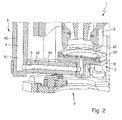
- FIG. 2 a schematic perspective and partially sectional view of another device 1 is shown, wherein again a treatment member 2 is shown in the form of a filling member 20.
- a closure 3 is provided, wherein the closure 3 has indeed been pivoted into the cleaning position in the pivoting plane Y, but the membrane 32 is not yet exposed to the corresponding pressure medium. Thus, the treatment opening 22 is not completely sealed.
- the reinforcement 320 of the membrane 32 is in FIG. 2 Good to see and is here in the form of a circular or annular plate formed, which is applied to the membrane 32.
- the radius of the circular plate of the reinforcement 320 substantially corresponds to the outer contours of the edge region around the treatment opening 22, so that the reinforcement 320 can come into contact with the edge region of the treatment opening 22.
- a container holder 6 is shown, by means of which containers to be treated can be held on their neck ring and can thus be guided under the treatment member 2.
- the pivoting device 4 and in particular the rotary shaft 40 are in turn clearly visible.
- the pressurizing medium passage 5 is formed by the through-hole 50 in the rotating shaft 40 and the through-hole 52 in the boom 42.
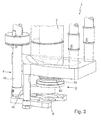
- FIG. 3 shows a schematic side view of the device 1 for treating a container of FIG. 2 , wherein again the treatment member 2 is shown in the form of the filling member 20, which is arranged above the container holder 6, so that a guided in the container holder 6 container can be treated by means of the treatment member 2.
- the treatment member 2 is a filling member 20, so that a filling product can be filled in the guided in the container holder 6 container.
- FIG. 3 the closure 3 is again shown in the cleaning position, but the membrane 32 is not yet loaded with the pressure medium, so that a fluid-tight closing of the Treatment opening 22 has not been completed.
- the swivel device 4 is likewise shown schematically and essentially has the rotary shaft 40, on which the shutter 3 is held over the boom 42. By simply rotating the rotary shaft 40 such that a lifting or lowering movement does not take place, the shutter 3 moves from the production position to the cleaning position and back again.
Abstract
Die vorliegende Erfindung betrifft eine Vorrichtung (1) zum Behandeln eines Behälters, bevorzugt in einer Getränkeabfüllanlage, besonders bevorzugt zum Befüllen eines Behälters mit einem Füllprodukt, umfassend ein Behandlungsorgan (2) mit einer Behandlungsöffnung (22) zum Behandeln des Behälters mit einem Behandlungsfluid, einen Verschluss (3) zum Verschließen der Behandlungsöffnung (22) zur Reinigung des Behandlungsorgans (2), und eine Schwenkvorrichtung (4) zum Bewegen des Verschlusses (3) von einer die Behandlungsöffnung (22) zur Behandlung des Behälters freilassenden Produktionsposition in eine die Behandlungsöffnung (22) verschließende Reinigungsposition, wobei der Verschluss (3) durch die Schwenkvorrichtung (4) in einer bezüglich des Behandlungsorgans (2) ortsfesten Ebene (Y) verschwenkbar ist.The present invention relates to a device (1) for treating a container, preferably in a beverage filling plant, particularly preferably for filling a container with a filling product, comprising a treatment member (2) having a treatment opening (22) for treating the container with a treatment fluid A closure (3) for closing the treatment opening (22) for cleaning the treatment organ (2), and a pivoting device (4) for moving the closure (3) from a production position leaving the treatment opening (22) open to treat the container. 22) closing cleaning position, wherein the closure (3) by the pivoting device (4) in a relative to the treatment member (2) stationary plane (Y) is pivotable.
Description
Die vorliegende Erfindung betrifft eine Vorrichtung zum Behandeln eines Behälters, bevorzugt in einer Getränkeabfüllanlage, besonders bevorzugt zum Befüllen eines Behälters mit einem Füllprodukt. Die vorliegende Erfindung betrifft weiterhin ein Verfahren zur Reinigung der Vorrichtung zum Behandeln der Behälter.The present invention relates to a device for treating a container, preferably in a beverage filling plant, particularly preferably for filling a container with a filling product. The present invention further relates to a method for cleaning the apparatus for treating the containers.
In Getränkeabfüllanlagen ist es bekannt, Behälter mit einem Behandlungsorgan zu behandeln. Ein solches Behandlungsorgan kann dabei beispielsweise ein Füllorgan sein, welches eine Behandlungsöffnung in Form einer Füllöffnung aufweist, durch welche hindurch ein Behandlungsfluid in Form eines Füllprodukts in den Behälter gelangt. Weiterhin ist es bekannt, den zu behandelnden Behälter mit Spülvorrichtungen beziehungsweise Rinsern zu behandeln, wobei hier eine Behandlungsöffnung des jeweiligen Behandlungsorgans in Form einer entsprechenden Spülöffnung vorhanden ist, durch welche hindurch ein Behandlungsfluid in Form eines Spülfluids in den zu behandelnden Behälter eintritt. Es ist weiterhin bekannt, Behälter durch das Einbringen eines Reinigungsfluids zu reinigen, wobei das entsprechende Behandlungsorgan dann in Form eines Reinigungsorgans vorgesehen ist, welches eine Behandlungsöffnung in Form der Austrittsöffnung für das Behandlungsfluid in Form des Reinigungsfluids aufweist.In beverage filling plants, it is known to treat containers with a treatment organ. Such a treatment member may be, for example, a filling member having a treatment opening in the form of a filling opening through which a treatment fluid in the form of a filling product passes into the container. Furthermore, it is known to treat the container to be treated with rinsing devices or rinsers, in which case a treatment opening of the respective treatment member is present in the form of a corresponding flushing opening, through which a treatment fluid in the form of a flushing fluid enters the container to be treated. It is also known to clean containers by introducing a cleaning fluid, wherein the corresponding treatment member is then provided in the form of a cleaning member having a treatment opening in the form of the outlet opening for the treatment fluid in the form of the cleaning fluid.
In Getränkeabfüllanlagen ist es üblich, die genannten Behandlungsorgane in festgelegten Zeitabständen zu reinigen. Eine solche Reinigung kann beispielsweise dann durchgeführt werden, wenn das mittels eines Füllorgans abzufüllende Füllprodukt gewechselt wird und entsprechend eine vollständige Reinigung der das Füllprodukt führenden Kanäle und Bestandteile der Getränkeabfüllanlage durchgeführt werden muss, um danach wieder ein sortenreines Abfüllen zu gewährleisten. Weiterhin ist es bekannt, aus hygienischen Gründen periodisch eine Anlagenreinigung durchzuführen, um zu verhindern, dass sich mikrobiologische Verunreinigungen ausbilden, welche das Füllprodukt verunreinigen könnten.In beverage filling plants, it is customary to clean said treatment organs at specified intervals. Such a cleaning can be carried out, for example, when the filling product to be filled by means of a filler is exchanged and, correspondingly, a complete cleaning of the filling product-carrying channels and components of the beverage filling plant has to be carried out in order then to ensure again a sorted filling. Furthermore, it is known for hygienic reasons periodically Perform equipment cleaning to prevent the formation of microbiological contaminants that could contaminate the fill product.
Zur Durchführung einer Reinigung des Behandlungsorgans ist es bekannt, zunächst die Behandlungsöffnungen des Behandlungsorgans mittels eines Verschlusses fluiddicht zu verschließen. Dann wird ein Reinigungsmedium über die Kanäle, die im Produktionsbetrieb das Behandlungsfluid - beispielsweise das Füllprodukt - führen, in das Behandlungsorgan eingeleitet, um die Reinigung des Behandlungsorgans durchzuführen. Das Reinigungsmedium kann dann aufgrund des aufgesetzten Verschlusses nicht über die Behandlungsöffnung ablaufen, sondern wird über einen separaten Reinigungskanal abgezogen, welcher beispielsweise oberhalb der Behandlungsöffnung des das Behandlungsmedium führenden Kanals abzweigt. Das Reinigungsmedium kann entsprechend das Behandlungsorgan durchströmen, tritt aber nicht aus der Behandlungsöffnung aus.To carry out a cleaning of the treatment member, it is known to first fluid-tightly close the treatment openings of the treatment member by means of a closure. Then, a cleaning medium via the channels, which in the production operation, the treatment fluid - for example, the filling product - lead introduced into the treatment device to perform the cleaning of the treatment member. The cleaning medium can then not drain through the treatment opening due to the attached closure, but is withdrawn via a separate cleaning channel, which branches off, for example, above the treatment opening of the channel leading to the treatment medium. The cleaning medium can accordingly flow through the treatment member, but does not escape from the treatment opening.
In einer Variante wird das Reinigungsmedium zur Reinigung des Behandlungsorgans über einen separaten Reinigungskanal in das Behandlungsorgan eingeleitet, und dann über den im Produktionsbetrieb das Behandlungsfluid führenden Kanal im Behandlungsorgan abgezogen, so dass hier quasi ein Rückwärtsspülen der das Behandlungsfluid führenden Kanäle im Behandlungsorgan ermöglicht wird. Auch hier tritt das Reinigungsmedium nicht aus der Behandlungsöffnung aus.In one variant, the cleaning medium for cleaning the treatment member is introduced via a separate cleaning channel in the treatment member, and then withdrawn via the leading in the production operation, the treatment fluid channel in the treatment organ, so that here quasi a backward flushing of the treatment fluid leading channels in the treatment device is made possible. Again, the cleaning medium does not escape from the treatment opening.
Diese Reinigungsart, in welcher die Behandlungsöffnung des Behandlungsorgans zum Reinigen des Behandlungsorgans mit einem Verschluss verschlossen wird und die das Behandlungsfluid führenden Kanäle im Behandlungsorgan mit einem Reinigungsmedium gespült werden, ohne dass dieses aus der Behandlungsöffnung austritt, wird auch als "Cleaning in Place" (CIP) oder "Sterilisation in Place" (SIP) bezeichnet, da das Behandlungsorgan zur Durchführung der Reinigung nicht entfernt, ausgebaut oder auseinandergenommen werden muss.This type of cleaning, in which the treatment opening of the treatment member for cleaning the treatment member is closed with a closure and the treatment fluid leading channels are flushed in the treatment member with a cleaning medium, without this exits the treatment opening is also called "cleaning in place" (CIP ) or "Sterilization in Place" (SIP), since the treatment organ need not be removed, disassembled or disassembled to carry out the cleaning.
Der die Behandlungsöffnung verschließende Verschluss ist dabei üblicherweise in Form einer Verschlusskappe ausgebildet, welche die Behandlungsöffnung des Behandlungsorgans dichtend abdichtet. Hierzu wird der Verschluss beziehungsweise die Verschlusskappe mittels einer Schwenkvorrichtung aus einer Produktionsposition, in welcher die Behandlungsöffnung freigegeben ist und das Behandlungsorgan zum Behandeln des Behälters dient, in eine Reinigungsposition verschwenkt, in welcher die Behandlungsöffnung fluiddicht verschlossen ist und eine Reinigung des Behandlungsorgans durchgeführt wird.The closure closing the treatment opening is usually designed in the form of a closure cap which seals the treatment opening of the treatment organ in a sealing manner. For this purpose, the closure or the closure cap by means of a pivoting device from a production position in which the treatment opening is released and the treatment member is used to treat the container in a cleaning position pivoted, in which the treatment opening is closed in a fluid-tight manner and a cleaning of the treatment member is performed.
Die Schwenkvorrichtung weist dabei üblicherweise eine Drehwelle auf, welche über einen Ausleger mit der entsprechenden Verschlusskappe verbunden ist. Mittels einer kombinierten Dreh-Hubbewegung dieser Drehwelle wird die Verschlusskappe von der Produktionsposition in die Reinigungsposition und wieder zurück in die Produktionsposition verschwenkt. Um das eigentliche Abdichten zu ermöglichen, führt die Drehwelle dabei neben der Schwenkbewegung eine Hubbewegung aus, mittels welcher die Verschlusskappe angehoben wird und auf die Behandlungsöffnung aufgepresst wird, wenn sich die Verschlusskappe in der Reinigungsposition befindet. Entsprechend ist eine aufwändige Schwenkvorrichtung notwendig, um die kombinierte Dreh-Hubbewegung auszuführen und damit den Verschluss von der Produktionsposition in die Reinigungsposition und wieder zurück zu bewegen. Solche einschwenkbaren Verschlusskappen in Form von CIP-Kappen mit einer Dreh-Hubvorrichtung sind beispielsweise aus der
Ausgehend von dem bekannten Stand der Technik ist es eine Aufgabe der vorliegenden Erfindung, eine Vorrichtung zum Behandeln eines Behälters anzugeben, welche einen vereinfachten Aufbau bereitstellt, sowie ein Verfahren zur Reinigung der Vorrichtung anzugeben.Starting from the known prior art, it is an object of the present invention to provide a device for treating a container, which provides a simplified structure, and to provide a method for cleaning the device.
Diese Aufgabe wird durch eine Vorrichtung zum Behandeln eines Behälters mit den Merkmalen des Anspruchs 1 gelöst. Vorteilhafte Weiterbildungen ergeben sich aus den Unteransprüchen.This object is achieved by a device for treating a container having the features of
Entsprechend wird eine Vorrichtung zum Behandeln eines Behälters, bevorzugt in einer Getränkeabfüllanlage, besonders bevorzugt zum Befüllen eines Behälters mit einem Füllprodukt, umfassend ein Behandlungsorgan mit einer Behandlungsöffnung zum Behandeln des Behälters mit einem Behandlungsfluid, einen Verschluss zum Verschließen der Behandlungsöffnung zur Reinigung des Behandlungsorgans, und eine Schwenkvorrichtung zum Bewegen des Verschlusses von einer die Behandlungsöffnung zur Behandlung des Behälters freilassenden Produktionsposition in eine die Behandlungsöffnung verschließende Reinigungsposition vorgeschlagen. Erfindungsgemäß ist der Verschluss durch die Schwenkvorrichtung in einer bezüglich des Behandlungsorgans ortsfesten Ebene verschwenkbar.Accordingly, a device for treating a container, preferably in a beverage filling plant, particularly preferably for filling a container with a filling product, comprising a treatment member having a treatment opening for treating the container with a treatment fluid, a closure for closing the treatment opening for cleaning the treatment member, and a pivoting device for moving the closure of a treatment opening for the treatment of the container release production position proposed in a treatment opening closing cleaning position. According to the invention, the closure can be pivoted by the pivoting device in a plane which is stationary relative to the treatment element.
Dadurch, dass die Schwenkvorrichtung den Verschluss von der Produktionsposition in die Reinigungsposition in einer bezüglich des Behandlungsorgans ortsfesten Ebene verschwenkt, kann auf eine aufwändige Trajektorie zur Bewegung des Verschlusses und damit auf eine aufwändige mechanische Ausbildung der Schwenkvorrichtung verzichtet werden. Durch die Verschwenkung in einer ortsfesten Ebene muss die Schwenkvorrichtung entsprechend nur eine Rotation um eine Schwenkachse herum ausführen. Hub- beziehungsweise Absenkbewegungen des Verschlusses sind nicht notwendig. Entsprechend kann die Schwenkvorrichtung durch einen einfachen Rotationsantrieb, beispielsweise einen Elektromotor oder einen Druckluftantrieb, ausgebildet sein. Es erübrigt sich damit, eine aufwändige Steuerung für das Anheben beziehungsweise Absenken des Verschlusses zum Abdichten der Behandlungsöffnung in der Reinigungsposition vorzusehen.Due to the fact that the pivoting device pivots the closure from the production position into the cleaning position in a plane fixed relative to the treatment member, a complex trajectory for moving the closure and thus a complex mechanical design of the pivoting device can be dispensed with. Due to the pivoting in a stationary plane, the pivoting device must accordingly execute only one rotation about a pivot axis. Lifting or lowering movements of the closure are not necessary. Accordingly, the pivoting device can be formed by a simple rotary drive, for example an electric motor or a compressed air drive. It is therefore unnecessary to provide a complex control for raising or lowering the closure for sealing the treatment opening in the cleaning position.
Die Schwenkvorrichtung verschwenkt den Verschluss bevorzugt möglichst knapp unter die Behandlungsöffnung, so dass die ortsfeste Ebene, in welcher der Verschluss verschwenkt wird, so ausgebildet ist, dass ein Abdichten der Behandlungsöffnung mit dem Verschluss erreicht werden kann.The pivoting device preferably pivots the closure as close as possible under the treatment opening, so that the stationary plane in which the closure is pivoted is designed so that a sealing of the treatment opening with the closure can be achieved.
In einer besonders bevorzugten Ausbildung weist der Verschluss eine Membran auf, welche in der Reinigungsposition durch Beaufschlagen mit einem Druckmedium zur Abdichtung an die Behandlungsöffnung anpressbar ist. Die Membran ist bevorzugt mit Druckluft, Reinigungsmedium oder einem beliebigen anderen Medium beaufschlagbar, derart, dass in der Reinigungsposition ein abdichtendes Verschließen der Behandlungsöffnung des Behandlungsorgans durch den Verschluss erreicht wird. Durch das Bereitstellen der Membran kann erreicht werden, dass trotz der einfachen Verschwenkung des Verschlusses in einer ortsfesten Ebene bezüglich des Behandlungsorgans ein fluiddichtes und druckfestes Abdichten der Behandlungsöffnung des Behandlungsorgans erreicht werden kann. Durch ein Beaufschlagen der Membran mit einem entsprechenden Druckmedium kann die Membran dann an die Behandlungsöffnung angepresst werden. Durch die Wahl des Druckes, mittels welchem die Membran an die Behandlungsöffnung angepresst wird, kann die Druckfestigkeit der Abdichtung der Behandlungsöffnung eingestellt werden. Mit anderen Worten kann über das Bereitstellen der Membran in dem Verschluss ein druckfestes Abdichten der Behandlungsöffnung erreicht werden, so dass ein Reinigungsvorgang beziehungsweise ein Sterilisationsvorgang bei hohen Drücken des jeweiligen Reinigungs- beziehungsweise Sterilisationsmediums durchgeführt werden kann.In a particularly preferred embodiment, the closure has a membrane, which can be pressed in the cleaning position by applying a pressure medium for sealing against the treatment opening. The membrane is preferably acted upon with compressed air, cleaning medium or any other medium, such that in the cleaning position, a sealing closure of the treatment opening of the treatment member is achieved by the closure. By providing the membrane can be achieved that, despite the simple pivoting of the closure in a stationary plane with respect to the treatment member, a fluid-tight and pressure-tight sealing of the treatment opening of the treatment member can be achieved. By applying the membrane with a corresponding pressure medium, the membrane can then be pressed against the treatment opening. By choosing the pressure by means of which the membrane is pressed against the treatment opening, the pressure resistance of the sealing of the treatment opening can be adjusted. In other words, by providing the membrane in the closure, a pressure-tight sealing of the treatment opening can be achieved, so that a cleaning process or a sterilization process can be carried out at high pressures of the respective cleaning or sterilization medium.
Bevorzugt weist die Membran einen Verstärkungsbereich auf, welcher bevorzugt den Außenkonturen der Behandlungsöffnung folgt. Der Verstärkungsbereich kann beispielsweise in Form einer plattenförmigen Verstärkung in dem Bereich der Membran ausgebildet sein, welcher an die Behandlungsöffnung angepresst wird. Durch die Verstärkung kann ein gleichmäßigeres Anpressen der Membran an dem Behandlungsorgan erreicht werden, so dass ein zuverlässiges und druckfestes Abdichten der Behandlungsöffnung ermöglicht wird. Der Verstärkungsbereich ermöglicht weiterhin, dass ein gleichmäßiges Anlegen der Membran an das Behandlungsorgan zur Abdichtung der Behandlungsöffnung erreicht wird, und nicht ein zufälliges Leck durch das Ausweichen des Membranmaterials an einer Stelle mit eventuell leicht niedrigerer Anpresskraft auftreten kann.Preferably, the membrane has a reinforcement region, which preferably follows the outer contours of the treatment opening. The reinforcing region may, for example, be in the form of a plate-shaped reinforcement in the region of the membrane which is pressed against the treatment opening. By reinforcing a more uniform pressing of the membrane can be achieved on the treatment member, so that a reliable and pressure-tight sealing of the treatment opening is made possible. The reinforcing area further allows uniform application of the membrane to the treatment member to seal the treatment opening, and not accidental leakage due to deflection of the membrane material at a location with possibly a slightly lower contact force.
Bevorzugt verschwenkt die Schwenkvorrichtung den Verschluss um eine Drehachse herum, wobei die Drehachse bevorzugt auf dem Teilkreis einer Rundläuferbehälterbehandlungsmaschine angeordnet ist und/oder exzentrisch zur Rotationsachse eines Karussells der Rundläuferbehandlungsmaschine angeordnet ist. Besonders bevorzugt ist jedem Behandlungsorgan eine eigene Schwenkvorrichtung mit Verschluss direkt zugeordnet, welche entsprechend zusammen mit dem Behandlungsorgan auf einem Teilkreis einer Rundläuferbehälterbehandlungsmaschine angeordnet ist. Durch die individuelle Zuordnung der Schwenkvorrichtung und des Verschlusses lässt sich das Verschließen einer jeden Behandlungsöffnung in einer Rundläuferbehälterbehandlungsmaschine so justieren, dass eine optimale Dichtwirkung erreicht wird. Weiterhin lassen sich das Behandlungsorgan und die Schwenkvorrichtung zusammen mit dem Verschluss einzeln ansteuern beziehungsweise im Wartungs- oder Defektfall modular der Rundläuferbehälterbehandlungsmaschine entnehmen und dann modular austauschen.Preferably, the pivoting device pivots the closure about an axis of rotation, wherein the axis of rotation is preferably arranged on the pitch circle of a rotary container treatment machine and / or is arranged eccentrically to the rotational axis of a carousel of the rotary treatment machine. Particularly preferably, each treatment member is assigned its own pivoting device with closure directly, which is arranged correspondingly together with the treatment member on a pitch circle of a rotary container treatment machine. By the individual assignment of the pivoting device and the closure, the closure of each treatment opening in a rotary container treatment machine can be adjusted so that an optimum sealing effect is achieved. Furthermore, the treatment member and the pivoting device can be controlled individually together with the closure or, in the case of maintenance or defect, removed modularly from the rotary container treatment machine and then exchanged modularly.
Bevorzugt ist in dem Verschluss anstelle oder zusätzlich zu der Membran ein Kolben vorgesehen, mittels welchem der Verschluss die Behandlungsöffnung verschließt. Der Kolben kann hierzu entweder eine Dichtung oder ein entsprechend geformtes Teil, welches komplementär zu dem die Behandlungsöffnung umgebenden Bereich des Behandlungsorgans ausgebildet ist, umfassen, um ein entsprechendes Abdichten zu erreichen.Preferably, a piston is provided in the closure instead of or in addition to the membrane, by means of which the closure closes the treatment opening. For this purpose, the piston may comprise either a seal or a correspondingly shaped part, which is complementary to the region of the treatment member surrounding the treatment opening, in order to achieve a corresponding sealing.
Die Schwenkvorrichtung umfasst bevorzugt eine Drehwelle, welche sich entlang der Drehachse erstreckt, und mittels welcher der Verschluss von der Produktionsposition in die Reinigungsposition verschwenkbar ist. Besonders bevorzugt weist die Drehwelle einen Druckmedienkanal zur Beaufschlagung der Membran und/oder des Kolbens des Verschlusses mit einem Druckmedium, bevorzugt mit Reinigungsmedium oder Druckluft, auf. Auf diese Weise kann das benötigte Druckmedium, welches die Membran und/oder den Kolben zum druckdichten Anpressen beaufschlagt, ohne externe Druckmedienschläuche beziehungsweise Druckmedienleitungen zugeführt werden. Entsprechend können auf diese Weise Teile eingespart werden, wodurch die Gesamtvorrichtung weniger komplex und damit weniger anfällig wird und gleichzeitig einfacherer zu reinigen und zu hygienisieren ist.The pivoting device preferably comprises a rotary shaft, which extends along the axis of rotation, and by means of which the closure can be pivoted from the production position into the cleaning position. Particularly preferably, the rotary shaft to a pressure medium channel to Actuation of the membrane and / or the piston of the closure with a pressure medium, preferably with cleaning medium or compressed air on. In this way, the required pressure medium, which acts on the membrane and / or the piston for pressure-tight pressing, can be supplied without external pressure medium hoses or pressure medium lines. Accordingly, parts can be saved in this way, whereby the overall device is less complex and thus less vulnerable and at the same time easier to clean and to sanitize.
Die oben beschriebene Aufgabe wird weiterhin durch ein Verfahren mit den Merkmalen des Anspruchs 11 gelöst. Vorteilhafte Weiterbildungen des Verfahrens ergeben sich aus den Unteransprüchen.The object described above is further achieved by a method having the features of claim 11. Advantageous developments of the method will become apparent from the dependent claims.
Entsprechend wird ein Verfahren zum Reinigen einer Vorrichtung zum Behandeln eines Behälters, bevorzugt in einer Getränkeabfüllanlage, vorgeschlagen, umfassend das Verschließen einer Behandlungsöffnung eines Behandlungsorgans zum Behandeln eines Behälters mittels eines Verschlusses und Beaufschlagen des verschlossenen Behandlungsorgans mit einem Reinigungsfluid. Erfindungsgemäß wird der Verschluss zum Verschließen der Behandlungsöffnung von einer die Behandlungsöffnung zur Behandlung des Behälters freilassenden Produktionsposition in einer bezüglich des Behandlungsorgans ortsfesten Ebene in eine die Behandlungsöffnung verschließende Reinigungsposition verschwenkt.Accordingly, a method for cleaning a device for treating a container, preferably in a beverage filling plant, is proposed, comprising closing a treatment opening of a treatment member for treating a container by means of a closure and applying a cleaning fluid to the closed treatment member. According to the invention, the closure for closing the treatment opening is pivoted from a production position leaving the treatment opening open for treatment of the container in a position fixed relative to the treatment organ into a cleaning position closing the treatment opening.
Bevorzugte weitere Ausführungsformen und Aspekte der vorliegenden Erfindung werden durch die nachfolgende Beschreibung der Figuren näher erläutert. Dabei zeigen:
Figur 1- eine schematische Schnittzeichnung durch eine Vorrichtung zum Behandeln eines Behälters in Form eines Füllorgans;
Figur 2- eine schematische, perspektivische und teilgeschnittene Ansicht einer weiteren Vorrichtung zum Behandeln eines Behälters; und
Figur 3- eine schematische perspektivische Seitenansicht der Vorrichtung aus
Figur 2 .
- FIG. 1
- a schematic sectional view through an apparatus for treating a container in the form of a filling member;
- FIG. 2
- a schematic, perspective and partially sectional view of another device for treating a container; and
- FIG. 3
- a schematic perspective side view of the device
FIG. 2 ,
Im Folgenden werden bevorzugte Ausführungsbeispiele anhand der Figuren beschrieben. Dabei werden gleiche, ähnliche oder gleichwirkende Elemente in den unterschiedlichen Figuren mit identischen Bezugszeichen bezeichnet und auf eine wiederholte Beschreibung dieser Elemente wird in der nachfolgenden Beschreibung teilweise verzichtet, um Redundanzen zu vermeiden.In the following, preferred embodiments will be described with reference to the figures. In this case, identical, similar or equivalent elements in the different figures are denoted by identical reference numerals and a repeated description of these elements will be omitted in the following description in part in order to avoid redundancies.
Weiterhin ist ein Verschluss 3 zum Verschließen der Behandlungsöffnung 22 gezeigt, wobei die Behandlungsöffnung 22 des Behandlungsorgans 2 zum Reinigen und/oder Sterilisieren des Behandlungsorgans 2 mittels des Verschlusses 3 verschlossen wird. Der Verschluss 3 weist einen Träger 30 auf, an welchem eine Membran 32 angeordnet ist. Zwischen der Membran 32 und dem Träger 30 ist entsprechend ein Volumen 34 ausgebildet, welches mit einem Druckmedium derart beaufschlagt werden kann, dass die Membran 32 expandiert wird und mit dem Behandlungsorgan 2 so in Kontakt tritt, dass die Behandlungsöffnung 22 fluiddicht und bevorzugt auch druckdicht abgedichtet wird.Furthermore, a
Der Druck des Druckmediums, welches in das Volumen 34 zwischen dem Träger 30 und der Membran 32 eingebracht wird, bestimmt den Anpressdruck der Membran 32 an das Behandlungsorgan 2 und damit auch den Maximaldruck eines Reinigungsmediums, welcher auf die Behandlungsöffnung 22 aufgebracht werden kann, ohne dass die mittels des Verschlusses 3 aufgebrachte Abdichtung versagt.The pressure of the pressure medium, which is introduced into the
Der Verschluss 3 wird über eine Schwenkvorrichtung 4 von der in
Die Schwenkvorrichtung 4 verschwenkt den Verschluss 3 in einer bezüglich des Behandlungsorgans 2 ortsfesten Verschwenkebene Y von der Behandlungsposition in die Produktionsposition und wieder zurück. Entsprechend muss die Schwenkvorrichtung 4 keinerlei Hub- oder Absenkbewegung auf den Verschluss 3 aufbringen. Die Abdichtung der Behandlungsöffnung 22 des Behandlungsorgans 2 wird durch ein entsprechendes Beaufschlagen des Volumens 34 zwischen dem Träger 30 und der Membran 32 mit einem Druckmedium bewirkt.The
Die Schwenkvorrichtung 4 kann damit recht einfach ausgebildet sein, da lediglich eine Rotation der Drehwelle 40 um die Schwenkachse X herum notwendig ist, eine Hubbewegung aber nicht erfolgt und auch nicht vorgesehen ist. Die Schwenkvorrichtung 4 kann entsprechend über einen einfachen Elektromotor oder einen druckluftbetriebenen Rotationsmechanismus so verschwenkt werden, dass der Verschluss 3 von der Produktionsposition in die Reinigungsposition und wieder zurück verschwenkt werden kann. Damit ergibt sich auch eine einfache Lagerung der Drehwelle 40.The
Der Verschluss 3 ist über einen Ausleger 42 mit der Drehwelle 40 verbunden, wobei sich der Ausleger 42 beispielsweise radial von der Drehwelle 40 fort erstreckt.The
Die Drehwelle 40 und der Ausleger 42 weisen einen gemeinsamen Kanal 5 auf, durch welchen hindurch das Druckmedium in das Volumen 34 zwischen dem Träger 30 und der Membran 32 eingebracht werden kann. Der Kanal 5 wird in den in den Figuren gezeigten Ausführungsbeispielen durch eine in der Drehwelle 40 eingebrachte Durchgangsbohrung 50 und eine in den Ausleger 42 eingebrachte Durchgangsbohrung 52 ausgebildet. Die beiden Durchgangsbohrungen 50, 52 sind dabei entsprechend durchgängig miteinander verbunden und so gegeneinander abgedichtet, dass ein druckfester Kanal 5 ausgebildet wird, der sich von einer in den Figuren nicht gezeigten Quelle für das Druckmedium zu dem Volumen 34 zwischen dem Träger 30 und der Membran 32 erstreckt.The
Auf zusätzliche Druckmedienleitungen zum Zuleiten des Druckmediums zu dem Volumen 34 kann so verzichtet werden.On additional print media lines for supplying the pressure medium to the
In der Reinigungsposition, welche in
Das Behandlungsorgan 2 beziehungsweise die Behandlungsöffnung 22 sind bevorzugt symmetrisch zu einer Achse B des Behandlungsorgans 2 ausgebildet. Die Achse B des Behandlungsorgans 2 und die Schwenkachse X liegen bevorzugt jeweils auf einem Teilkreis einer Rundläuferbehälterbehandlungsmaschine. Entsprechend sind sowohl die Achse B des Behandlungsorgans 2, als auch die Schwenkachse X exzentrisch zur Rotationsachse eines Karussells der Rundläuferbehälterbehandlungsmaschine angeordnet.The
Jedes Behandlungsorgan 2 in einer Rundläuferbehälterbehandlungsmaschine ist bevorzugt mit einer eigenen Schwenkvorrichtung 4 und einem eigenen Verschluss 3 versehen. Entsprechend kann die beispielsweise in
Die Membran 32 weist in dem gezeigten Ausführungsbeispiel in dem Bereich der Behandlungsöffnung 22 eine Verstärkung 320 auf. Die Verstärkung 320 folgt im Wesentlichen den Außenkonturen der Randbereiche der Behandlungsöffnung 22. Durch die Verstärkung 320 kann ein Ausbeulen der Membran 32 im Bereich der Anlageflächen um die Behandlungsöffnung 22 herum verhindert werden. Weiterhin wird ein gleichmäßiges Anlegen der Membran 32 an das Behandlungsorgan 2 erreicht, wodurch die Dichtwirkung der Membran 32 weiter verbessert wird. Auf diese Weise kann auch ein ungewolltes Öffnen der Abdichtung an einer möglichen Schwachstelle der Membran 32 verhindert werden.In the exemplary embodiment shown, the
Die Membran 32 kann aus einem Kunststoff, bevorzugt einem elastischen Kunststoff, hergestellt sein. Die Membran 32 kann aber auch in Form eines Balgs bereitgestellt werden, der Kunststoff oder Metall enthält oder aus diesen Werkstoffen besteht.The
Anstelle der in
In
Die Verstärkung 320 der Membran 32 ist in
Eine Behälterhalterung 6 ist gezeigt, mittels welcher zu behandelnde Behälter an ihrem Halsring gehalten werden können und so unter das Behandlungsorgan 2 geführt werden können.A
Die Schwenkvorrichtung 4 und insbesondere die Drehwelle 40 sind wiederum klar zu erkennen. Der Kanal 5 zur Beaufschlagung mit einem Druckmedium ist mittels der Durchgangsbohrung 50 in der Drehwelle 40 und der Durchgangsbohrung 52 in dem Ausleger 42 ausgebildet.The
In
Soweit anwendbar, können alle einzelnen Merkmale, die in den einzelnen Ausführungsbeispielen dargestellt sind, miteinander kombiniert und/oder ausgetauscht werden, ohne den Bereich der Erfindung zu verlassen.Where applicable, all individual features illustrated in the individual embodiments may be combined and / or interchanged without departing from the scope of the invention.
- 11
- Vorrichtung zum Behandeln eines BehältersApparatus for treating a container
- 22
- Behandlungsorgantreatment member
- 2020
- FüllorganFilling head
- 2222
- Behandlungsöffnungtreatment opening
- 2424
- Füllventilfilling valve
- 2626
- FüllproduktauslaufFüllproduktauslauf
- 240240
- FüllventilkegelFüllventilkegel
- 242242
- FüllventilkegelsitzFüllventilkegelsitz
- 33
- Verschlussshutter
- 3030
- Trägercarrier
- 3232
- Membranmembrane
- 3434
- Volumenvolume
- 320320
- Verstärkung der MembranReinforcement of the membrane
- 44
- Schwenkvorrichtungswivel device
- 4040
- Drehwellerotary shaft
- 4242
- Auslegerboom
- 55
- Kanalchannel
- 5050
- DurchgangsbohrungThrough Hole
- 5252
- DurchgangsbohrungThrough Hole
- 66
- Behälterhalterungcontainer holder
- XX
- Schwenkachseswivel axis
- YY
- Schwenkebenepivot plane
- BB
- Achse des BehandlungsorgansAxis of the treatment organ
Claims (12)
dadurch gekennzeichnet, dass
der Verschluss (3) durch die Schwenkvorrichtung (4) in einer bezüglich des Behandlungsorgans (2) ortsfesten Ebene (Y) verschwenkbar ist.Device (1) for treating a container, preferably in a beverage filling installation, particularly preferably for filling a container with a filling product, comprising a treatment member (2) with a treatment opening (22) for treating the container with a treatment fluid, a closure (3) for Closing the treatment opening (22) for cleaning the treatment member (2), and a pivoting device (4) for moving the closure (3) from a production position leaving the treatment opening (22) open for treatment of the container into a cleaning position closing the treatment opening (22),
characterized in that
the closure (3) can be pivoted by the pivoting device (4) in a plane (Y) fixed relative to the treatment element (2).
dadurch gekennzeichnet, dass
der Verschluss (3) zum Verschließen der Behandlungsöffnung (22) von einer die Behandlungsöffnung (22) zur Behandlung des Behälters freilassenden Produktionsposition in einer bezüglich des Behandlungsorgans (2) ortsfesten Ebene (Y) in eine die Behandlungsöffnung (22) verschließende Reinigungsposition verschwenkt wird.Method for cleaning a device (1) for treating a container, preferably in a beverage filling installation, comprising closing a treatment opening (22) of a treatment member (2) for treating a container by means of a closure (3) and applying pressure to the closed treatment member (2) a cleaning fluid,
characterized in that
the closure (3) for closing the treatment opening (22) is pivoted from a production position leaving the treatment opening (22) open in a position (Y) fixed relative to the treatment element (2) into a cleaning position closing the treatment opening (22).
Applications Claiming Priority (1)
| Application Number | Priority Date | Filing Date | Title |
|---|---|---|---|
| DE102013113494.7A DE102013113494A1 (en) | 2013-12-04 | 2013-12-04 | Apparatus for treating a container in a beverage bottling plant and a method for cleaning the apparatus |
Publications (1)
| Publication Number | Publication Date |
|---|---|
| EP2881360A1 true EP2881360A1 (en) | 2015-06-10 |
Family
ID=52015916
Family Applications (1)
| Application Number | Title | Priority Date | Filing Date |
|---|---|---|---|
| EP14196300.9A Ceased EP2881360A1 (en) | 2013-12-04 | 2014-12-04 | Device for treating a container in a drink filling assembly and method for cleaning said device |
Country Status (3)
| Country | Link |
|---|---|
| EP (1) | EP2881360A1 (en) |
| CN (1) | CN104692312A (en) |
| DE (1) | DE102013113494A1 (en) |
Families Citing this family (4)
| Publication number | Priority date | Publication date | Assignee | Title |
|---|---|---|---|---|
| DE102016201313A1 (en) * | 2016-01-29 | 2017-08-03 | Robert Bosch Gmbh | Device and method for dosing liquid or pasty contents in containers |
| CN105905853A (en) * | 2016-05-27 | 2016-08-31 | 杭州中亚机械股份有限公司 | Piston for filling valve |
| CN105967130A (en) * | 2016-05-27 | 2016-09-28 | 杭州中亚机械股份有限公司 | Piston for filling valve |
| CN110562900A (en) * | 2019-10-12 | 2019-12-13 | 广州达意隆包装机械股份有限公司 | Automatic false cup of liquid filling machine and filling equipment |
Citations (6)
| Publication number | Priority date | Publication date | Assignee | Title |
|---|---|---|---|---|
| WO2007070222A1 (en) * | 2005-12-14 | 2007-06-21 | Evergreen Packaging International B.V. | Container filling apparatus including cleaning system |
| DE102008030291A1 (en) * | 2008-06-30 | 2009-12-31 | Khs Ag | Filling element and filling machine for filling containers |
| US20100084046A1 (en) * | 2007-01-22 | 2010-04-08 | Sidel Participations | Filling machine provided with a cleaning device |
| DE102009033557A1 (en) | 2009-07-16 | 2011-01-20 | Krones Ag | Device for bottling beverages with CIP cap control |
| DE102010027623A1 (en) | 2010-07-19 | 2012-01-19 | Krones Aktiengesellschaft | Filling device for containers with cleaning system |
| DE102010027624A1 (en) | 2010-07-19 | 2012-01-19 | Krones Aktiengesellschaft | Device for treating containers with rinsing cap |
Family Cites Families (4)
| Publication number | Priority date | Publication date | Assignee | Title |
|---|---|---|---|---|
| DE19608764B4 (en) * | 1996-03-07 | 2004-03-18 | Khs Maschinen- Und Anlagenbau Ag | Device for treating bottles, cans and. like. |
| FR2950609B1 (en) * | 2009-09-29 | 2011-12-09 | Sidel Participations | FILLING MACHINE EQUIPPED WITH A CLEANING DEVICE IN PLACE WITH INDIVIDUAL COLLECTOR ELEMENTS |
| DE102009051160A1 (en) * | 2009-10-29 | 2011-05-05 | Khs Gmbh | Filling element and filling machine for filling containers |
| DE102011111496B3 (en) * | 2011-08-30 | 2012-06-06 | Khs Gmbh | Lifting element with retractable rinsing sleeve |
-
2013
- 2013-12-04 DE DE102013113494.7A patent/DE102013113494A1/en not_active Withdrawn
-
2014
- 2014-12-04 CN CN201410737128.6A patent/CN104692312A/en active Pending
- 2014-12-04 EP EP14196300.9A patent/EP2881360A1/en not_active Ceased
Patent Citations (6)
| Publication number | Priority date | Publication date | Assignee | Title |
|---|---|---|---|---|
| WO2007070222A1 (en) * | 2005-12-14 | 2007-06-21 | Evergreen Packaging International B.V. | Container filling apparatus including cleaning system |
| US20100084046A1 (en) * | 2007-01-22 | 2010-04-08 | Sidel Participations | Filling machine provided with a cleaning device |
| DE102008030291A1 (en) * | 2008-06-30 | 2009-12-31 | Khs Ag | Filling element and filling machine for filling containers |
| DE102009033557A1 (en) | 2009-07-16 | 2011-01-20 | Krones Ag | Device for bottling beverages with CIP cap control |
| DE102010027623A1 (en) | 2010-07-19 | 2012-01-19 | Krones Aktiengesellschaft | Filling device for containers with cleaning system |
| DE102010027624A1 (en) | 2010-07-19 | 2012-01-19 | Krones Aktiengesellschaft | Device for treating containers with rinsing cap |
Also Published As
| Publication number | Publication date |
|---|---|
| DE102013113494A1 (en) | 2015-06-11 |
| CN104692312A (en) | 2015-06-10 |
Similar Documents
| Publication | Publication Date | Title |
|---|---|---|
| EP2010447B1 (en) | Filling element and filling machine with a filling element | |
| EP2146922B1 (en) | Filling system and method for controlling a filling system | |
| EP0539791B1 (en) | Method and apparatus for filling bottles or similar containers with a liquid product | |
| EP3286130B1 (en) | Filling valve assembly and filling machine | |
| EP2881360A1 (en) | Device for treating a container in a drink filling assembly and method for cleaning said device | |
| DE102011111496B3 (en) | Lifting element with retractable rinsing sleeve | |
| EP2409946B1 (en) | Device for handling containers with flushing cap | |
| EP2398731B1 (en) | Method for the pressurised filling of bottles or like containers, and filling system and filling machine for carrying out said method | |
| DE10342415A1 (en) | Container handling machine | |
| EP2969894A1 (en) | Method and filling machine for filling cans or the like containers with liquid contents | |
| DE102011111483A1 (en) | Container handling machine | |
| EP2915772B1 (en) | Device for filling a container with a filling product | |
| EP2969895B1 (en) | Rotary distributor for filling machines | |
| EP3020531A1 (en) | Pressure control device | |
| DE102019103095A1 (en) | Device for treating a container | |
| DE2948633A1 (en) | DEVICE FOR CLOSING VESSELS | |
| WO2016066275A2 (en) | Piston arrangement for pumping a liquid | |
| EP3554987B1 (en) | Filling element arrangement, and filling machine | |
| DE2947035C2 (en) | Filling element for counter pressure vessel filling machine | |
| EP2848577A1 (en) | Device for dosing a product into a container | |
| EP2534089B1 (en) | Filling system for filling containers in a pressurized manner | |
| DE102016106210A1 (en) | Apparatus and method for filling a container with a filling product | |
| DE102015112790A1 (en) | Method for cleaning and / or disinfecting closing elements of a closing machine, closing machine and closing element | |
| DE4331463A1 (en) | Machine for sterilising and filling vessels under back pressure | |
| DE102019135472A1 (en) | Filling machine |
Legal Events
| Date | Code | Title | Description |
|---|---|---|---|
| PUAI | Public reference made under article 153(3) epc to a published international application that has entered the european phase |
Free format text: ORIGINAL CODE: 0009012 |
|
| 17P | Request for examination filed |
Effective date: 20141204 |
|
| AK | Designated contracting states |
Kind code of ref document: A1 Designated state(s): AL AT BE BG CH CY CZ DE DK EE ES FI FR GB GR HR HU IE IS IT LI LT LU LV MC MK MT NL NO PL PT RO RS SE SI SK SM TR |
|
| AX | Request for extension of the european patent |
Extension state: BA ME |
|
| R17P | Request for examination filed (corrected) |
Effective date: 20151203 |
|
| RBV | Designated contracting states (corrected) |
Designated state(s): AL AT BE BG CH CY CZ DE DK EE ES FI FR GB GR HR HU IE IS IT LI LT LU LV MC MK MT NL NO PL PT RO RS SE SI SK SM TR |
|
| 17Q | First examination report despatched |
Effective date: 20170619 |
|
| STAA | Information on the status of an ep patent application or granted ep patent |
Free format text: STATUS: THE APPLICATION HAS BEEN REFUSED |
|
| 18R | Application refused |
Effective date: 20191120 |