EP2881159A1 - Système de capture et de récupération de gaz et de particules - Google Patents
Système de capture et de récupération de gaz et de particules Download PDFInfo
- Publication number
- EP2881159A1 EP2881159A1 EP13824776.2A EP13824776A EP2881159A1 EP 2881159 A1 EP2881159 A1 EP 2881159A1 EP 13824776 A EP13824776 A EP 13824776A EP 2881159 A1 EP2881159 A1 EP 2881159A1
- Authority
- EP
- European Patent Office
- Prior art keywords
- self
- priming
- gases
- induced flow
- particles
- Prior art date
- Legal status (The legal status is an assumption and is not a legal conclusion. Google has not performed a legal analysis and makes no representation as to the accuracy of the status listed.)
- Withdrawn
Links
- 239000007789 gas Substances 0.000 title claims abstract description 46
- 239000002245 particle Substances 0.000 title claims abstract description 23
- 238000000034 method Methods 0.000 claims abstract description 21
- 230000008569 process Effects 0.000 claims abstract description 19
- 238000004140 cleaning Methods 0.000 claims abstract description 15
- 238000005202 decontamination Methods 0.000 claims abstract description 3
- 230000003588 decontaminative effect Effects 0.000 claims abstract description 3
- 238000005086 pumping Methods 0.000 claims abstract 5
- 238000004064 recycling Methods 0.000 claims abstract 2
- 239000000428 dust Substances 0.000 claims description 30
- 239000007788 liquid Substances 0.000 claims description 5
- 238000000605 extraction Methods 0.000 claims description 3
- 230000008859 change Effects 0.000 claims description 2
- 238000010521 absorption reaction Methods 0.000 claims 1
- 238000012544 monitoring process Methods 0.000 claims 1
- 238000005457 optimization Methods 0.000 claims 1
- 230000035945 sensitivity Effects 0.000 claims 1
- XLYOFNOQVPJJNP-UHFFFAOYSA-N water Substances O XLYOFNOQVPJJNP-UHFFFAOYSA-N 0.000 description 8
- 238000011109 contamination Methods 0.000 description 4
- 238000013461 design Methods 0.000 description 4
- 239000012716 precipitator Substances 0.000 description 4
- 230000007613 environmental effect Effects 0.000 description 3
- 229910052500 inorganic mineral Inorganic materials 0.000 description 3
- 239000011707 mineral Substances 0.000 description 3
- 238000000926 separation method Methods 0.000 description 3
- 238000009825 accumulation Methods 0.000 description 2
- 239000000356 contaminant Substances 0.000 description 2
- 238000010586 diagram Methods 0.000 description 2
- 230000000694 effects Effects 0.000 description 2
- 239000004744 fabric Substances 0.000 description 2
- 238000005259 measurement Methods 0.000 description 2
- 238000005065 mining Methods 0.000 description 2
- 230000009467 reduction Effects 0.000 description 2
- 238000004062 sedimentation Methods 0.000 description 2
- FFBHFFJDDLITSX-UHFFFAOYSA-N benzyl N-[2-hydroxy-4-(3-oxomorpholin-4-yl)phenyl]carbamate Chemical compound OC1=C(NC(=O)OCC2=CC=CC=C2)C=CC(=C1)N1CCOCC1=O FFBHFFJDDLITSX-UHFFFAOYSA-N 0.000 description 1
- 238000006243 chemical reaction Methods 0.000 description 1
- 239000003795 chemical substances by application Substances 0.000 description 1
- 150000001875 compounds Chemical class 0.000 description 1
- 238000009833 condensation Methods 0.000 description 1
- 230000005494 condensation Effects 0.000 description 1
- 238000001514 detection method Methods 0.000 description 1
- 239000006185 dispersion Substances 0.000 description 1
- 239000012153 distilled water Substances 0.000 description 1
- 230000005684 electric field Effects 0.000 description 1
- 239000012717 electrostatic precipitator Substances 0.000 description 1
- 238000003912 environmental pollution Methods 0.000 description 1
- 239000012530 fluid Substances 0.000 description 1
- 230000008570 general process Effects 0.000 description 1
- 230000005484 gravity Effects 0.000 description 1
- 230000003993 interaction Effects 0.000 description 1
- 238000005461 lubrication Methods 0.000 description 1
- 238000012423 maintenance Methods 0.000 description 1
- 230000007246 mechanism Effects 0.000 description 1
- 238000006386 neutralization reaction Methods 0.000 description 1
- 230000001376 precipitating effect Effects 0.000 description 1
- 230000003134 recirculating effect Effects 0.000 description 1
- 238000011084 recovery Methods 0.000 description 1
- 238000005070 sampling Methods 0.000 description 1
- 238000007873 sieving Methods 0.000 description 1
- 239000007921 spray Substances 0.000 description 1
- 238000012546 transfer Methods 0.000 description 1
- 239000002699 waste material Substances 0.000 description 1
Images

Classifications
-
- B—PERFORMING OPERATIONS; TRANSPORTING
- B01—PHYSICAL OR CHEMICAL PROCESSES OR APPARATUS IN GENERAL
- B01D—SEPARATION
- B01D47/00—Separating dispersed particles from gases, air or vapours by liquid as separating agent
- B01D47/10—Venturi scrubbers
-
- B—PERFORMING OPERATIONS; TRANSPORTING
- B01—PHYSICAL OR CHEMICAL PROCESSES OR APPARATUS IN GENERAL
- B01D—SEPARATION
- B01D53/00—Separation of gases or vapours; Recovering vapours of volatile solvents from gases; Chemical or biological purification of waste gases, e.g. engine exhaust gases, smoke, fumes, flue gases, aerosols
- B01D53/14—Separation of gases or vapours; Recovering vapours of volatile solvents from gases; Chemical or biological purification of waste gases, e.g. engine exhaust gases, smoke, fumes, flue gases, aerosols by absorption
- B01D53/1412—Controlling the absorption process
-
- B—PERFORMING OPERATIONS; TRANSPORTING
- B01—PHYSICAL OR CHEMICAL PROCESSES OR APPARATUS IN GENERAL
- B01D—SEPARATION
- B01D53/00—Separation of gases or vapours; Recovering vapours of volatile solvents from gases; Chemical or biological purification of waste gases, e.g. engine exhaust gases, smoke, fumes, flue gases, aerosols
- B01D53/34—Chemical or biological purification of waste gases
- B01D53/74—General processes for purification of waste gases; Apparatus or devices specially adapted therefor
- B01D53/77—Liquid phase processes
- B01D53/78—Liquid phase processes with gas-liquid contact
-
- B—PERFORMING OPERATIONS; TRANSPORTING
- B01—PHYSICAL OR CHEMICAL PROCESSES OR APPARATUS IN GENERAL
- B01F—MIXING, e.g. DISSOLVING, EMULSIFYING OR DISPERSING
- B01F23/00—Mixing according to the phases to be mixed, e.g. dispersing or emulsifying
- B01F23/10—Mixing gases with gases
-
- B—PERFORMING OPERATIONS; TRANSPORTING
- B01—PHYSICAL OR CHEMICAL PROCESSES OR APPARATUS IN GENERAL
- B01F—MIXING, e.g. DISSOLVING, EMULSIFYING OR DISPERSING
- B01F25/00—Flow mixers; Mixers for falling materials, e.g. solid particles
- B01F25/30—Injector mixers
- B01F25/31—Injector mixers in conduits or tubes through which the main component flows
- B01F25/312—Injector mixers in conduits or tubes through which the main component flows with Venturi elements; Details thereof
- B01F25/3123—Injector mixers in conduits or tubes through which the main component flows with Venturi elements; Details thereof with two or more Venturi elements
- B01F25/31232—Injector mixers in conduits or tubes through which the main component flows with Venturi elements; Details thereof with two or more Venturi elements used simultaneously
-
- B—PERFORMING OPERATIONS; TRANSPORTING
- B01—PHYSICAL OR CHEMICAL PROCESSES OR APPARATUS IN GENERAL
- B01F—MIXING, e.g. DISSOLVING, EMULSIFYING OR DISPERSING
- B01F25/00—Flow mixers; Mixers for falling materials, e.g. solid particles
- B01F25/30—Injector mixers
- B01F25/31—Injector mixers in conduits or tubes through which the main component flows
- B01F25/312—Injector mixers in conduits or tubes through which the main component flows with Venturi elements; Details thereof
- B01F25/3124—Injector mixers in conduits or tubes through which the main component flows with Venturi elements; Details thereof characterised by the place of introduction of the main flow
- B01F25/31243—Eductor or eductor-type venturi, i.e. the main flow being injected through the venturi with high speed in the form of a jet
-
- B—PERFORMING OPERATIONS; TRANSPORTING
- B08—CLEANING
- B08B—CLEANING IN GENERAL; PREVENTION OF FOULING IN GENERAL
- B08B15/00—Preventing escape of dirt or fumes from the area where they are produced; Collecting or removing dirt or fumes from that area
- B08B15/04—Preventing escape of dirt or fumes from the area where they are produced; Collecting or removing dirt or fumes from that area from a small area, e.g. a tool
-
- C—CHEMISTRY; METALLURGY
- C21—METALLURGY OF IRON
- C21B—MANUFACTURE OF IRON OR STEEL
- C21B7/00—Blast furnaces
- C21B7/002—Evacuating and treating of exhaust gases
-
- C—CHEMISTRY; METALLURGY
- C21—METALLURGY OF IRON
- C21C—PROCESSING OF PIG-IRON, e.g. REFINING, MANUFACTURE OF WROUGHT-IRON OR STEEL; TREATMENT IN MOLTEN STATE OF FERROUS ALLOYS
- C21C5/00—Manufacture of carbon-steel, e.g. plain mild steel, medium carbon steel or cast steel or stainless steel
- C21C5/28—Manufacture of steel in the converter
- C21C5/38—Removal of waste gases or dust
- C21C5/40—Offtakes or separating apparatus for converter waste gases or dust
-
- B—PERFORMING OPERATIONS; TRANSPORTING
- B01—PHYSICAL OR CHEMICAL PROCESSES OR APPARATUS IN GENERAL
- B01D—SEPARATION
- B01D2247/00—Details relating to the separation of dispersed particles from gases, air or vapours by liquid as separating agent
- B01D2247/04—Regenerating the washing fluid
-
- B—PERFORMING OPERATIONS; TRANSPORTING
- B01—PHYSICAL OR CHEMICAL PROCESSES OR APPARATUS IN GENERAL
- B01D—SEPARATION
- B01D2247/00—Details relating to the separation of dispersed particles from gases, air or vapours by liquid as separating agent
- B01D2247/14—Fan arrangements for providing induced draft
-
- B—PERFORMING OPERATIONS; TRANSPORTING
- B01—PHYSICAL OR CHEMICAL PROCESSES OR APPARATUS IN GENERAL
- B01D—SEPARATION
- B01D2252/00—Absorbents, i.e. solvents and liquid materials for gas absorption
- B01D2252/10—Inorganic absorbents
- B01D2252/103—Water
-
- B—PERFORMING OPERATIONS; TRANSPORTING
- B01—PHYSICAL OR CHEMICAL PROCESSES OR APPARATUS IN GENERAL
- B01D—SEPARATION
- B01D2257/00—Components to be removed
- B01D2257/60—Heavy metals or heavy metal compounds
-
- B—PERFORMING OPERATIONS; TRANSPORTING
- B01—PHYSICAL OR CHEMICAL PROCESSES OR APPARATUS IN GENERAL
- B01D—SEPARATION
- B01D2257/00—Components to be removed
- B01D2257/80—Water
-
- B—PERFORMING OPERATIONS; TRANSPORTING
- B01—PHYSICAL OR CHEMICAL PROCESSES OR APPARATUS IN GENERAL
- B01D—SEPARATION
- B01D2258/00—Sources of waste gases
- B01D2258/02—Other waste gases
- B01D2258/025—Other waste gases from metallurgy plants
-
- B—PERFORMING OPERATIONS; TRANSPORTING
- B01—PHYSICAL OR CHEMICAL PROCESSES OR APPARATUS IN GENERAL
- B01D—SEPARATION
- B01D53/00—Separation of gases or vapours; Recovering vapours of volatile solvents from gases; Chemical or biological purification of waste gases, e.g. engine exhaust gases, smoke, fumes, flue gases, aerosols
- B01D53/002—Separation of gases or vapours; Recovering vapours of volatile solvents from gases; Chemical or biological purification of waste gases, e.g. engine exhaust gases, smoke, fumes, flue gases, aerosols by condensation
-
- C—CHEMISTRY; METALLURGY
- C21—METALLURGY OF IRON
- C21B—MANUFACTURE OF IRON OR STEEL
- C21B2100/00—Handling of exhaust gases produced during the manufacture of iron or steel
- C21B2100/40—Gas purification of exhaust gases to be recirculated or used in other metallurgical processes
- C21B2100/44—Removing particles, e.g. by scrubbing, dedusting
-
- Y—GENERAL TAGGING OF NEW TECHNOLOGICAL DEVELOPMENTS; GENERAL TAGGING OF CROSS-SECTIONAL TECHNOLOGIES SPANNING OVER SEVERAL SECTIONS OF THE IPC; TECHNICAL SUBJECTS COVERED BY FORMER USPC CROSS-REFERENCE ART COLLECTIONS [XRACs] AND DIGESTS
- Y02—TECHNOLOGIES OR APPLICATIONS FOR MITIGATION OR ADAPTATION AGAINST CLIMATE CHANGE
- Y02P—CLIMATE CHANGE MITIGATION TECHNOLOGIES IN THE PRODUCTION OR PROCESSING OF GOODS
- Y02P10/00—Technologies related to metal processing
- Y02P10/25—Process efficiency
Definitions
- the present invention relates to a system for capturing and recovering polluting gases and particles in the air, in a size greater than 75 micrograms per cubic meter, with sizes of 2.5 to 30 micrometers, the methodology having as an objective the task of removing the polluting gas and dust. Said objective being established by the detection of the presence of said polluting gas and dust as well as the cleaning efficiency control.
- the recovery and capture systems of polluting gas and dust are installed wherein a high environmental polluting particles concentration is generated, said concentration range being risky to people, the environment and the service life of machines.
- Cleaning apparatuses have to consider: the feature of the gas, the environmental temperature or the process temperature generated by the gas compound or polluting dust, the water steam condensation, minerals and gases present therein. Cleaning apparatuses also depend on the features of the contaminant due to its abrasive or corrosive condition.
- cleaning apparatuses One distinguishing feature of cleaning apparatuses is the one related to the direct energy requirements or auxiliary sources to be used, which in order to be produced, need energy or a process, wherein said energy is obtained as a natural resource. Generally, they are hot gases from a process, air and steam under pressure.
- Electrostatic Precipitators are very efficient for cleaning air and cooled-smelter gases which use high potentials of electric fields and its process consists of: gas ionization, charging of dust particles, transport of particles to the collection surface, neutralization and removal of the charge in the collected dust and removal of dust particles.
- Dust collectors comprised by fabric sleeve filters having a lower efficiency for cleaning air use the principle of intercepting the polluted air current by using big filters. They use electric power to move the extractors as well as the compressed air at high pressure for removing dust. Its process comprises the stage in which the dust is captured and drawn, the interception of air for the removal of dust particles, trapped in the fabric sleeve filters, pulses of air at high pressure directed towards the sleeves for removing the accumulated dust, collecting the dust dropped by gravity. The clean air at the end of the extractor is directed through the ducts having an outlet towards the atmosphere.
- Dust suppressants of low efficiency work by means of a dissemination mechanism wherein a fog created with water and air under pressure is used. Thereby creating a moisture dispersion for capturing and precipitating the dust.
- Wet Collectors are not normally used in mining however they are classified as: Centrifugal Humidifiers which use the centrifugal force to accelerate the dust particle, impregnating it on some wet surface collectors.
- Wet dynamic precipitators use water spray in a compartment loaded with dust particles by means of the mechanical separation of the air from the wet dust.
- the Venturi-type collector uses the Venturi effect to absorb gases or dust mixing it with water to channel them towards a separation section.
- the invention for capturing and recovering gases and particles is detailed, which is an apparatus that uses two aspiration processes one is carried out by means of self-priming units in a steam flow and the other by means of an extractor driven by a motor with speed control.
- the self-priming units are interspersed in the contaminated air current next to a restriction or elbow having the purpose of disaggregation due to the density of gases and particles present in the contaminated air.
- Every mineral treatment process generates dust due to the mineral crushing, transfer, transport, sieving and stacking stages. It is important to deliver an apparatus which is adapted to the structural design of the dust-generating process unit.
- the invention due to its structural simplicity is designed to modify the measures to be used depending on the capture contaminated air volumes and the level of contamination. By means of the control methodology it is possible to modify the parameters linked to the cleaning process.
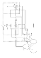
- Figure 1 is the general process and instrumentation design of the apparatus for capturing and recovering gases and particles.
- the diagram of figure 1 is the diagram of the process, equipment and instrumentation involved in the general explanatory operation of the invention.
- the main process is initiated in the gases and particles contamination source such as for example, a Pierce-Smith Reactor or Converter 1, the extractor hood 2, the support pipe of self-priming pumps 3 which is the first dragging of gases and particles by aspiration.
- the induced draft fan or Extractor 4 is the most important agent of aspiration
- the second Support pipe of self-priming pumps 5 is also used for dragging the gasses and particles by means of aspiration
- the water dynamic precipitator 6 is the last cleaning stage and where the clean air exits to the atmosphere.
- the secondary process comprises a separation tank for the accumulation of the captured gases and particles 7, the steam fired boiler 8, solenoid valves for controlling the distilled water feed 12, a steam-feed control valve 13 and a discharge waste valve 14 which are involved in controlling the steam.
- the clean distillate enters the dynamic precipitator 6 and the boiler 8.
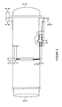
- FIG. 1 is the objective of the invention and represents the elements indicated as induced flow apparatus 3 and 5 of figure 1 .
- Figure 2 is the detail of the contaminated gas inlet 21 and the clean gas outlet 29 in the induced flow apparatus, the clean steam inlet 27 as well as the contaminated steam outlet 28.
- the self-priming units are structurally inserted towards the inner part of the induced flow apparatus.
- a circular manifold 22 from where are distributed the eight lines similar to the aspiration line 23, located at a distance equivalent to the average diameter of the cylindrical section of the contaminated air inlet 21, typical sample of the other lines, in the extracted portion is inwardly visualized the self-priming pump 24 and the outlet of each line 25 towards the manifold 26 to be concentrated on the discharge line 28 when returning to the tank, dust sedimentation element absorbed by the steam/distillate.
- the self-priming pump is detailed as well as how this works inside the induced flow pipe.
- the inlet chamber 31 normally are injected liquids or steam at high pressure in order to create suction inside the pump, due to the narrowing and expansion of the nozzle 32.
- the suction chamber 33 at the discharge nozzle produces the aspiring effect on the suction line 34, thereby suctioning the dust contaminated air, being mixed to exit through a parallel section 35, wherein the diffusor 36 as well as the discharge 37 are at a pressure higher than the one of the suction.
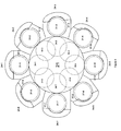
- Figure 4 shows the distribution of the large-scale self-priming pumps in a plane which shifts the 8 aforementioned units (each one of them being represented in figure 3 ) to the inside of the duct which conveys gases and dust 21 and it also shows its distribution as a sub-index from 1 to 8 with the numbering associated to figures 2 and 3 .
- the suction ducts are 34-1, 34-2, 34-3, 34-4, 34-5, 34-6, 34-7, 34-8.
Landscapes
- Chemical & Material Sciences (AREA)
- Engineering & Computer Science (AREA)
- Chemical Kinetics & Catalysis (AREA)
- Environmental & Geological Engineering (AREA)
- Manufacturing & Machinery (AREA)
- Materials Engineering (AREA)
- Metallurgy (AREA)
- Organic Chemistry (AREA)
- Analytical Chemistry (AREA)
- General Chemical & Material Sciences (AREA)
- Oil, Petroleum & Natural Gas (AREA)
- Biomedical Technology (AREA)
- Health & Medical Sciences (AREA)
- Separation Of Particles Using Liquids (AREA)
- Gas Separation By Absorption (AREA)
Applications Claiming Priority (2)
| Application Number | Priority Date | Filing Date | Title |
|---|---|---|---|
| CL2012002186A CL2012002186A1 (es) | 2012-08-03 | 2012-08-03 | Sistema de captación y extracción de gases y particulas contaminantes que son partes de un circuito cerado de vapor a presion, incluyendo dos estacionaes de recuperacion de gases cilindricas conectadas a una campana de extraccion, un ventilador de tiro inducido y un precipitador dinamico de agua. |
| PCT/CL2013/000050 WO2014019101A1 (fr) | 2012-08-03 | 2013-08-02 | Système de capture et de récupération de gaz et de particules |
Publications (2)
| Publication Number | Publication Date |
|---|---|
| EP2881159A1 true EP2881159A1 (fr) | 2015-06-10 |
| EP2881159A4 EP2881159A4 (fr) | 2016-03-30 |
Family
ID=50027038
Family Applications (1)
| Application Number | Title | Priority Date | Filing Date |
|---|---|---|---|
| EP13824776.2A Withdrawn EP2881159A4 (fr) | 2012-08-03 | 2013-08-02 | Système de capture et de récupération de gaz et de particules |
Country Status (7)
| Country | Link |
|---|---|
| US (1) | US20160121257A1 (fr) |
| EP (1) | EP2881159A4 (fr) |
| AU (1) | AU2013299280A1 (fr) |
| CA (1) | CA2880223A1 (fr) |
| CL (1) | CL2012002186A1 (fr) |
| PE (1) | PE20150366A1 (fr) |
| WO (1) | WO2014019101A1 (fr) |
Cited By (1)
| Publication number | Priority date | Publication date | Assignee | Title |
|---|---|---|---|---|
| CN110860169A (zh) * | 2019-08-21 | 2020-03-06 | 南京梅宝新型建材有限公司 | 一种磁材烘干窑烟气净化处理装置以及处理方法 |
Families Citing this family (5)
| Publication number | Priority date | Publication date | Assignee | Title |
|---|---|---|---|---|
| CA2900101C (fr) | 2014-08-13 | 2023-01-03 | Harnischfeger Technologies, Inc. | Systeme de suppression automatique de la poussiere et methode |
| CN112717603A (zh) * | 2020-11-17 | 2021-04-30 | 临泉县睿鑫建材有限公司 | 一种空心砖生产用除尘装置 |
| CN115212783A (zh) * | 2022-07-26 | 2022-10-21 | 天地壹号饮料股份有限公司 | 自动除尘硅藻土预混合装置 |
| CN116116191B (zh) * | 2023-01-04 | 2023-11-14 | 广东鸿星环保科技有限公司 | 一种同流向高效脱硝治理系统 |
| CN117861403B (zh) * | 2023-12-09 | 2025-05-06 | 温州市排水有限公司 | 一种低噪音除臭净化设备 |
Family Cites Families (10)
| Publication number | Priority date | Publication date | Assignee | Title |
|---|---|---|---|---|
| GB314906A (en) * | 1928-04-18 | 1929-07-18 | Verner Russell Chadwick | Improvements in or relating to the washing of smoke and fumes from furnaces and the like |
| US2757987A (en) * | 1952-05-08 | 1956-08-07 | Allen Sherman Hoff Co | Method and apparatus for transporting finely divided solids |
| US3613333A (en) * | 1969-07-17 | 1971-10-19 | Hugh E Gardenier | Process and apparatus for cleaning and pumping contaminated industrial gases |
| US3707067A (en) * | 1970-07-13 | 1972-12-26 | Gerald P Dietrick | Gas scrubbing device |
| US3998626A (en) * | 1973-03-12 | 1976-12-21 | Pennsylvania Engineering Corporation | Method for air pollution control combined with safe recovery and control of gases from a bottom-blown steel converter vessel |
| ZA766846B (en) * | 1975-11-28 | 1977-10-26 | Lone Star Steel Co | Apparatus and process for the removal of pollutant material from gas streams |
| US4272499A (en) * | 1979-11-28 | 1981-06-09 | Lone Star Steel Company | Process and apparatus for the removal of particulate matter and reactive or water soluble gases from carrier gases |
| KR100436540B1 (ko) * | 2001-11-23 | 2004-06-19 | 한국수력원자력 주식회사 | Co₂ 분사제염 발생 오염입자 포집방법 및 장치 |
| DE102006061256B4 (de) * | 2006-12-22 | 2009-04-30 | Fette Gmbh | Filteranlage zum Abscheiden von Stäuben aus Gasen |
| CN201912865U (zh) * | 2010-12-22 | 2011-08-03 | 张映伟 | 烟雾粉尘滤清回收装置 |
-
2012
- 2012-08-03 CL CL2012002186A patent/CL2012002186A1/es unknown
-
2013
- 2013-08-02 EP EP13824776.2A patent/EP2881159A4/fr not_active Withdrawn
- 2013-08-02 PE PE2015000105A patent/PE20150366A1/es not_active Application Discontinuation
- 2013-08-02 AU AU2013299280A patent/AU2013299280A1/en not_active Abandoned
- 2013-08-02 WO PCT/CL2013/000050 patent/WO2014019101A1/fr not_active Ceased
- 2013-08-02 CA CA 2880223 patent/CA2880223A1/fr not_active Abandoned
- 2013-08-02 US US14/419,416 patent/US20160121257A1/en not_active Abandoned
Cited By (1)
| Publication number | Priority date | Publication date | Assignee | Title |
|---|---|---|---|---|
| CN110860169A (zh) * | 2019-08-21 | 2020-03-06 | 南京梅宝新型建材有限公司 | 一种磁材烘干窑烟气净化处理装置以及处理方法 |
Also Published As
| Publication number | Publication date |
|---|---|
| PE20150366A1 (es) | 2015-03-25 |
| WO2014019101A1 (fr) | 2014-02-06 |
| EP2881159A4 (fr) | 2016-03-30 |
| AU2013299280A1 (en) | 2015-02-19 |
| CA2880223A1 (fr) | 2014-02-06 |
| CL2012002186A1 (es) | 2012-10-05 |
| US20160121257A1 (en) | 2016-05-05 |
Similar Documents
| Publication | Publication Date | Title |
|---|---|---|
| EP2881159A1 (fr) | Système de capture et de récupération de gaz et de particules | |
| CN101400427A (zh) | 过滤城市环境中空气的方法和设备 | |
| KR101569721B1 (ko) | 소각로용 미세먼지 저감장치 | |
| CN104492756B (zh) | 一种石墨粉尘处理装置 | |
| Bogomolov et al. | On inertial systems, dust cleaning and dust removal equipment, and work areas in the production of aerated concrete from the hopper suction apparatus CSF | |
| CN109876575B (zh) | 烟尘过滤器及烟尘烟气采样设备 | |
| KR102169511B1 (ko) | 원전 해체용 방사화 콘크리트 포집 공조 시스템 | |
| KR20100009691U (ko) | 사이크론 전기집진기 | |
| CN108905476B (zh) | 一种工业厂房用气体过滤净化系统 | |
| CN201344552Y (zh) | 烟气预处理装置 | |
| CN104606994B (zh) | 除尘脱硝脱硫一体化装置 | |
| CN108716992B (zh) | 一种双极荷电-旋风除尘实验装置 | |
| CN111318122A (zh) | 一种高温含尘废气排放净化方法及其装置 | |
| CN205340436U (zh) | 螺旋水膜复合除尘装置 | |
| CN209173624U (zh) | 一种金属非金属矿山选矿厂局部喷雾除尘装置 | |
| CN204242278U (zh) | 一种纸币处理设备的集尘与消毒装置 | |
| CN211585872U (zh) | 一种模块化粉尘处理装置 | |
| CN104492599B (zh) | 一种石墨粉尘处理方法 | |
| CN103239965A (zh) | 一种组合式空气净化设备 | |
| CN109663446B (zh) | 一种零排放干选方法 | |
| CN210021565U (zh) | 一种适用于零排放干选系统的洁净风处理系统 | |
| CN209865667U (zh) | 一种新型工业烟尘过滤器 | |
| CN208287749U (zh) | 一种可循环废气处理装置 | |
| CN204219957U (zh) | 一种净化器颗粒物收集处理系统 | |
| CN219292346U (zh) | 一种预降尘装置及除尘系统 |
Legal Events
| Date | Code | Title | Description |
|---|---|---|---|
| PUAI | Public reference made under article 153(3) epc to a published international application that has entered the european phase |
Free format text: ORIGINAL CODE: 0009012 |
|
| 17P | Request for examination filed |
Effective date: 20150226 |
|
| AK | Designated contracting states |
Kind code of ref document: A1 Designated state(s): AL AT BE BG CH CY CZ DE DK EE ES FI FR GB GR HR HU IE IS IT LI LT LU LV MC MK MT NL NO PL PT RO RS SE SI SK SM TR |
|
| AX | Request for extension of the european patent |
Extension state: BA ME |
|
| DAX | Request for extension of the european patent (deleted) | ||
| RA4 | Supplementary search report drawn up and despatched (corrected) |
Effective date: 20160301 |
|
| RIC1 | Information provided on ipc code assigned before grant |
Ipc: B01D 47/10 20060101ALI20160224BHEP Ipc: B01D 53/00 20060101ALI20160224BHEP Ipc: B01D 50/00 20060101AFI20160224BHEP Ipc: C21C 5/40 20060101ALI20160224BHEP Ipc: C21B 7/00 20060101ALI20160224BHEP Ipc: B01F 3/02 20060101ALI20160224BHEP Ipc: B08B 15/04 20060101ALI20160224BHEP Ipc: B01D 53/78 20060101ALI20160224BHEP Ipc: B01F 5/04 20060101ALI20160224BHEP |
|
| R17P | Request for examination filed (corrected) |
Effective date: 20150226 |
|
| STAA | Information on the status of an ep patent application or granted ep patent |
Free format text: STATUS: THE APPLICATION IS DEEMED TO BE WITHDRAWN |
|
| 18D | Application deemed to be withdrawn |
Effective date: 20170301 |