EP2881007B1 - Mécanisme de verrouillage - Google Patents
Mécanisme de verrouillage Download PDFInfo
- Publication number
- EP2881007B1 EP2881007B1 EP13195480.2A EP13195480A EP2881007B1 EP 2881007 B1 EP2881007 B1 EP 2881007B1 EP 13195480 A EP13195480 A EP 13195480A EP 2881007 B1 EP2881007 B1 EP 2881007B1
- Authority
- EP
- European Patent Office
- Prior art keywords
- locking mechanism
- stationary
- spring
- mechanism according
- bearing
- Prior art date
- Legal status (The legal status is an assumption and is not a legal conclusion. Google has not performed a legal analysis and makes no representation as to the accuracy of the status listed.)
- Active
Links
Images


Classifications
-
- A—HUMAN NECESSITIES
- A47—FURNITURE; DOMESTIC ARTICLES OR APPLIANCES; COFFEE MILLS; SPICE MILLS; SUCTION CLEANERS IN GENERAL
- A47B—TABLES; DESKS; OFFICE FURNITURE; CABINETS; DRAWERS; GENERAL DETAILS OF FURNITURE
- A47B3/00—Folding or stowable tables
- A47B3/08—Folding or stowable tables with legs pivoted to top or underframe
- A47B3/0818—Folding or stowable tables with legs pivoted to top or underframe with manually actuated locking means
-
- A—HUMAN NECESSITIES
- A47—FURNITURE; DOMESTIC ARTICLES OR APPLIANCES; COFFEE MILLS; SPICE MILLS; SUCTION CLEANERS IN GENERAL
- A47B—TABLES; DESKS; OFFICE FURNITURE; CABINETS; DRAWERS; GENERAL DETAILS OF FURNITURE
- A47B3/00—Folding or stowable tables
- A47B3/08—Folding or stowable tables with legs pivoted to top or underframe
- A47B3/0809—Folding or stowable tables with legs pivoted to top or underframe with elastic locking means
- A47B3/0815—Folding or stowable tables with legs pivoted to top or underframe with elastic locking means the resilient force of the elastic locking means acting in a direction perpendicular to the axis of rotation of the leg
Definitions
- the present invention relates to a locking mechanism which locks a first part relative to a second part. When unlocked, either the first or second part can be pivoted relative to the other between at least one locked and at least one unlocked position.
- the locking mechanism of the present invention will often be used in connection with furnitures where a simple, light-weight solution is appreciated.
- the locking mechanism Due to the possibility of enclosing the movable parts of the locking mechanism in a closed or semi-closed profile the locking mechanism can be placed in positions where it will be visible as the user will see the outer surface of the profile and not the mechanism as such.
- US 2010/0175598 relates to a table with a swingable bow foot.
- the table comprises a table top and at least one bow foot which are swingable between a transportation position in which it is swung in so as to rest against a surface of the table top, and a swung out utilization position.
- the bow foot has a base limb and at least one table leg, the bow foot experiences an offset between its transportation position and its utilization position axially to its base limb, which offset is controlled by a control tenon (36) guided in a control track, wherein the control track is formed on the circumference of the base limb and the control tenon is firmly attached to the table top.
- a bar plate (46) comprises on its inner site facing the table top (12) a pocket-like recess (52) corresponding to bar elements (42A, 42B) in such a way that when the relevant bar element (42A, 42B) is engaged, the relevant bow foot is locked and cannot be swung.
- This mechanism is relatively complex i.e. it is constructed of many interacting parts, and the locking mechanism comprising a bar element and the recess of the bar plate has to be constructed of material having a high hardness in order to withstand stress. Also, forces are transferred to the table top via the bar plate and the swing axis, thereby necessitating that the table top possess a certain strength.
- DE202011101437U discloses a locking mechanism with a stationary part in the form of a bracket.
- the present invention was made in view of the prior art described above, and the object of the present invention is to provide a locking mechanism which is both simple, easy to operate and having a design which makes it acceptable to be placed in a position where it will be seen.
- the present invention provides a locking mechanism to be attached to a device or a device part comprising a first and a second part,
- the first part (1) can be at least partly positioned inside the stationary part (2) and the stationary part (2) is fixed to a part of a device.
- the stationary part (2) can be constituted by or be part of a device part such as a surface of a table top or a wall or a side of a wall mounted shelf.
- the release mechanism can be a release arm (1c, 1d) extending in a direction opposite the protruding part (1b).
- the release arm can function as a lever thereby reducing the strength needed by the user to unlock the locking mechanism.
- the part of the bearing (3, 3a, 3b) or the stationary part (2) or the independent part held in position by the stationary part (2) or by the bearing (3, 3a) having the fourth contact surface (14b) is made of steel or of a material having similar indentation hardness i.e. ability to resist deformation.
- the spring (7) or spring system can have a second attachment position on the stationary part (2).
- the spring (7) or spring system can have a second attachment position on the stationary part (2) which - relative to the swing axis a1 - is placed opposite the protruding part (1a) and the spring (7) is biased when extended i.e. the spring (7) pulls.
- the first part (1) can be unreleasably fixed to a surface of a table top and the second part (9) comprises a single table leg or a set of two table legs which are pivotable between a locked position in which the table legs support the table top, and an unlocked position in which the table legs are in a folded position.
- the bearing (3, 3a, 3b) can provide guiding means (10) providing an off-set in a direction perpendicular to the direction of rotation of the second part (9) when the second part (9) is pivoted from the locked to the unlocked position and the same or secondary guiding means provide an off-set in the opposite direction when the second part (9) is pivoted from the unlocked to the locked position.
- one part of the bearing (3a) can provide primary guiding means (10) providing an off-set in a direction both perpendicular to the direction of rotation of the second part (9) and parallel to the surface of attachment, when the second part is pivoted from the locked to the unlocked position, and a second part of the bearing (3b) can provide secondary guiding means (10) providing an off-set in the opposite direction of the first off-set when the second part (9) is pivoted from the unlocked position to the locked position.
- the guiding means (10) can be constituted by at least two inclined surfaces (10) corresponding to each their surface of respectively the first and the second protruding part (4).
- the locking mechanism can comprise means (6) for adjusting the distance between the first and second contact surfaces (1b, 4a) of respectively the first (1) and the second (9) part.
- the hinge connection (5, 6) can comprise two pointed screws (6) with round heads forming a line which line constituting the swing axis a1.
- the round heads of the pointed screws (6) may face the stationary part (2) and each round head may fit into a top recess of a screw bolt (5) being attached to the stationary part (2).
- the first part (1) can be unreleasably fixed to the lower surface of a table top or a shelf and the second part (9) comprises a part which is unreleasably and stationary fixed to a wall, allowing the table top or shelf to pivot between a locked position where the upper surface of the table top or shelf is placed perpendicularly relative to the wall and an unlocked position where the table top or shelf is parallel to the wall.
- the present invention may be used with a table.
- Closed profile is an object having a fixed, cross-sectional cut i.e. the cross-sectional view is the same through-out the length of the profile. Normally, such a profile is made by extrusion of e.g. metals or polymers. That the profile is closed means that the profile has a completely closed outer surface.
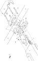
- Figure 1 shows an exploded view of a locking mechanism comprising a first 1 and a second part 9.
- the locking mechanism allows the first 1 and second 9 parts to pivot relative to each other when the locking mechanism is in a released state.
- the locking mechanism will allow one part of a device to swing relative to another part of the same device such as e.g. the device is a table and a pair of table legs are allowed to swing relative to a table top, the device is a vehicle and a tailboard is allowed to swing relative to the vehicle, the device is a wall mounted bed and the sleeping surface e.g. including a madras is allowed to swing relative to the wall, the device is a wall or seat mounted tray or table top which is allowed to swing relative to the wall or the seat etc.
- Fig. 2 and 3 show cut-through side views of the same embodiment as fig. 1 .
- Fig. 2 shows a cut-through side view where the cut has been made through the centre of the locking mechanism.
- Fig. 3 shows a cut-through side view where the cut has been made off the centre and instead shows how the fastening means for the bearing 3 fix the bearing 3 to the stationary part 2.
- the fastening means is constituted by four screw bolts 16.
- the locking mechanism comprises a stationary part 2 to which the first part 1 is fixed via a hinged connection, and a bearing 3, 3a, 3b in which the second part 9 is rotatably mounted.
- the stationary part 2 and the bearing 3 do not move relative to each other i.e. they are fixed relative to each other and relative to one of the device parts which the locking mechanism operates with.
- the stationary part 2 and the bearing is fixed to one device part and the second part either constitutes a second device part or is attached to a second device part.
- the bearing 3 can e.g. be provided with a cover plate 15 able to cover fastening means 16 for the bearing and making it possible to adapt the design of the locking mechanism to any desirable use or function without influencing the functionality of the locking mechanism.
- the first part 1 can be constituted by a single piece of material, e.g. it can e.g. be molded from a hard polymer such as glass reinforced nylon or steel, alternatively the first part 1 can be composed of separate pieces of material which are assembled and after assembling, the parts will be completely fixed and stationary relative to each other. If the first part 1 is composed of two or more pieces then each piece might be made of a material which is optimized in respect of weight and durability. I.e. if the locking mechanism is placed in a tray in an aeroplane it is important that each part weighs as little as possible, where as if a locking mechanism is used for e.g. holding a wall bed including a bottom and a madras which can be turned up or down, then it should be able to carry about 200 kg.
- the first part 1 comprises a first protruding part 1a provided with a first contact surface 1b at one end.
- the protruding part 1a extends in direction of the second part 9 and when the first part 1 is mounted in the locking mechanism and the locking mechanism is in a locked position, the first contact surface 1b will be in contact with the second part 9.
- the first protruding part 1a should be constructed of a relatively hard and wear resistant material as it should remain relatively unaffected by the contact during the life time of the locking mechanism. When using the word "relatively" it is indicated that the use of the locking mechanism will determine how hard and wear resistant the material needs to be.
- the first part 1 illustrated in fig. 1 is constructed of a flat part fixed on top of a rectangular block, the flat part extends toward the second part 9 as the first protruding part 1a, and the front surface i.e. the first contact surface 1b of the flat part is in contact with a corresponding surface of the second part 9.
- the contact between the first contact surface 1b and the actually prevents the second part 9 from rotating, the flat part has to be made of a material having a relatively high durability, "relatively high” means that the choice of material is influenced by the force the actual locking mechanism is subjected to.
- the first part 1 is also provided with a central part and the central part of the embodiment shown in fig. 1 provides an attachment position for a spring 7, the spring 7 forces the first part 1 into the locked position.
- the first part 1 is provided with some kind of release means which are able to provide a force big enough to overcome the force from the spring 7,
- the embodiment in fig. 1 is provided with a second protruding part 1c which extends in a direction opposite from the first protruding part 1a, when a relatively long handle part or release part 1d is attached to the second protruding part thereby providing a lever, it becomes easy for the user to overcome the force from the spring or spring system and release the first part 1 from the locked position.
- the hinged connection allows the first part 1 to pivot around a swing axis a1 between at least two positions, a first locked position and a second released or unlocked position.
- first locked position the first part 1 is forced into a locked position by a spring 7, and in the second unlocked or released position a user overcomes the force of the spring 7 and the user forces the first part 1 into the second released position.
- Figure 1-3 illustrates one embodiment of a hinged connection where two pointed screws 6 with round heads form a line which line represents the swing axis a1 (see fig. 2 ).
- the round heads of the pointed screws 6 face the stationary part 2 and fit into each their top recess of two screw bolts 5 which have been screwed into treads in the stationary part 2.
- the screw bolts 5 will normally be made of a very durable material such as steel.
- the spring 7 or spring system i.e. a plurality of springs has one or more attachment points on the stationary part 2 and one or more attachment points on the first protruding part 1a of the first part.
- the first part needs to have an attachment position for a spring or a spring system, but the attachment position could be at several positions, the attachment position e.g. depends on whether the spring or spring system which forces the first part into the locked position pushes or pulls.
- the spring 7 causes a movement of the protruding part 1a of the first part towards the circumferential surface of the second part 9 in order to keep the first protruding part 1a in contact with the second part 9, until the force provided by the spring is exceeded by a releasing force normally provided by the user.
- the attachment point for the spring 7 on the first part 1 is provided by a pointed screw 11 which extends from the "lower" side of the central part of the first part 1 which is the inside of an inner surface 19 of the stationary part 2.
- the attachment point could be constituted by a tap or hook protruding from the lower surface of the first part 1, such a part could be an integrated part of the first part 1.
- the inner surface 19 of the stationary part 2 is the side facing the device part to which the stationary part 2 is attached.
- the spring 7 is illustrated as a helical metal spring which pulls in order to get from a biased to a relaxed position.
- One end of the helical spring 7 is attached to the free end of the pointed screw 11; the opposite end of the helical spring 7 is attached to the stationary part 2, e.g. to a (not shown) screw which is screwed into a longitudinal track 22 provided in the profile constituting the stationary part 2.
- the longitudinal track 22 is placed centrally and close to the inner surface 19 of the stationary part 2.
- the first part 1 will be in an unlocked position when the first protruding part 1a is pivoted into a position where the first protruding part 4 of the second part 9 can pass below, i.e. rotate anticlockwise in the figure, the contact surface 1b of the first protruding part 1.
- a spring or spring system can be positioned anywhere in the system where it pushes or pulls in direction of the rotation.
- the position of the spring 7 in the embodiment of fig. 1-3 has the advantageous that it is possible to use a physically large spring such as a helical spring without having to e.g. increase the height of the stationary part 2.
- the second part 9 shown in fig. 1 has a circular or at least partly circular perifery provided with two protruding parts, a first protruding part 4 and a second protruding part 14.
- the first protruding part 4 has a contact surface 4a corresponding to the first contact surface 1b of the first part 1 and the second protruding part 14 has a contact surface 14a corresponding to the third contact surface 8a of either the bearing 3a or the stationary part 2 or an independent part 8.
- the second part 9 is immobilised in one position when the locking mechanism is locked and when the locking mechanism is released the second part 9 can rotate or pivot between at least two positions.
- the contact between the first and the second contact surfaces 1a and 4a on respectively the first part 1 and the second part 9 prevents the second part 9 from rotating or pivoting in one direction (i.e. anticlockwise according to the embodiment of fig. 1 ) when the locking mechanism is in a locked position
- the contact between the fourth and the third contact surfaces 8a and 14a on respectively the bearing 3a or the stationary part 2 or an independent part 8 and on the second part 9 prevent the second part 9 from rotating or pivoting in the opposite direction (i.e. clockwise according to the embodiment of fig. 1 ) when the locking mechanism is in a locked position.
- the bearing 3 fixes the position of the second part 9 relative to both the stationary part 2 and the first part 1, and makes it impossible for the second part 9 to move away from the first part 1.
- the locking mechanism can be provided with means to lock the second part 9 in the released or unlocked end position and/or to lock the second part 9 in one or more intermediate positions. Whether this feature is advantageous will depend on the actual use of the locking mechanism. According to the embodiment of fig. 1-3 , the second part 9 is locked by friction in the released or unlocked position, and need therefore not be released by any release means as such; thus, the user has to overcome the frictional resistance and tension of the spring 7 upon bringing the second part 9 back into the locked position.
- the fourth contact surface 8a can be constituted e.g. by a protruding part of either the bearing 3a or the stationary part 2 extending in direction of the second part, or alternatively the fourth contact surface 8a can be provided by a separate piece e.g. a rectangular block 8 as shown in fig. 1 , which is made of e.g. a hard and durable material such as steel. By making a separate piece it is possible to increase the wear resistance of the fourth contact surface without increasing the weight of the locking mechanism significantly.
- the locking mechanism will be provided with a means for adjusting the distance between the first and second part 1, 9 in order to make it possible to obtain a very precise contact between the first contact surface 1b of the first part and the second contact surface 4a of the second part 9 compensating for that the first and second part might not be made in accurate measures.
- This feature makes it possible to produce the first and second parts of the locking mechanism with a larger tolerance.
- the means 6 for adjusting the distance or contact between the first and second contact surfaces of respectively the first and the second part comprises the two bolts which are part of the hinged connection.
- the stationary part 2 provides a mounting for the first part 1 i.e. the first part 1 is fixed unreleasably via the hinged connection to the stationary part 2 and the stationary part 2 is fixed, normally unreleasably, to a device part able to swing relative to the second part 9.
- the stationary part 2 is constituted by a closed profile enclosing the hinged connection and the first part and providing a large part of the external surface of the locking mechanism.
- the design of the locking mechanism do not depend on the functions of the locking mechanism but allows for completely different functions such as providing handles for carrying the device on which the locking mechanism is mounted or providing attachment points for equipment to be used together with the device or just allowing a pleasing design which makes it acceptable to show the locking mechanism when the device on which it is mounted is e.g. folded together or up against a wall.
- a profile for stationary part 2 makes it possible to reduce the number of necessary parts when constructing the locking mechanism as most of the parts are either bolts screwed directly into the tracks of the profile or parts attached by the bolts which are screwed directly into the tracks of the profile. This reduces the number of necessary parts and simplifies the production.
- the outer or external surfaces of the locking mechanism are constituted entirely by the stationary part 2, i.e. the closed profile, and the cover plates 15 covering each end of the profile.
- the stationary part 2 can e.g. be a profile extruded of aluminium as this is a lightweight and inexpensive material.
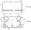
- Fig. 4a and 4b shows an embodiment of a stationary part
- fig. 4a shows a side view of the stationary part
- fig. 4b shows a cross-sectional end view of the stationary part.
- the profile constituting the stationary part 2 is furnished with the shown tracks in its full length, and the length of the profile is adapted to the first and the second part of the locking mechanism.
- the shown profile is closed i.e. the wall of the profile comprises a closed surface surrounding an enclosed space in which the first part 1 is placed, when the profile is closed it will normally be provided with one or more openings allowing a user to access e.g. the handle part 1c.
- the stationary part 2 is has an outer surface 18 which is facing way from the surface to which the locking mechanism is attached, and an inner surface 19 which is facing the surface of the device to which the locking mechanism is attached.
- the stationary part 2 further has two outward facing side surfaces 17 which each are provided with a recess or indentation 24 in the full length of the stationary part.
- the recess 24 might function as a finger grip if carrying the device which the locking mechanism is attached to.
- the outward facing side surfaces 17 is also provided with an external track 23 which also extends in the full length of the stationary part 2.
- Such an external track 23 can be used to permanently or temporarily attach extra parts to the device to which the stationary part 2 of the locking mechanism is attached.
- the part of the hinged connection attached to the stationary part 2 is constructed of two screw bolts 5 which are fixed in the stationary part 2.
- the screw bolts 5 are postioned in each of two longitudinal tracks 20 provided in the profile close to the middle of the profile thereby allowing the first part 1 to move both up and down.
- the screw bolts 5 are inserted from the open end of the stationary part 2 and screwed into the tracks 20.
- the profile of fig. 4 is also provided with longitudinal tracks 21 close to each corner of the profile, these four tracks 21 are adapted to receive the fastening means 16 i.e. the four screw bolts 16 shown in fig. 1 .
- a further track 22 positioned centrally and close to the inner surface of the stationary part 2 can be used for a bolt having a head to which head the spring 7 is attached i.e. representing the attachment point 12 of the spring with the stationary part 2.
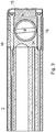
- the stationary part 2 will be provided with an opening 13 in an outer surface 18 or a side surface 17 through which opening 13 a user can manipulate the release part 1d.
- Fig. 8 shows an embodiment of a stationary part 2 provided with an opening 13 fitting to a release arm 1d, the release arm 1d is provided with a release button which fits closely into the opening 13.
- a bearing 3 according to the invention will be assembled from at least two parts 3a, 3b in order to make it possible to assembly the bearing 3 around the second part 9.
- the bearing can be provided with guiding means 10 causing a displacement of the second part in direction of the rotation axis of the second part 9 i.e. the second part 9 rotates in one direction and is simultaneously displaced along the axis which it rotates around.
- the guiding means 10, i.e. two inclined surfaces perpendicular to the surface of the second part 9, on the inner bearing part 3a is in contact with both end surfaces of the first protruding part 4 during rotation; and the guiding means 10 i.e. an inclined surface perpendicular to the surface of the second part 9, on the outer bearing 3b is in contact with one end surface of the second protruding part 14 during rotation of the second part 9.
- the contact between the guiding means 10 and the two protruding parts 4, 14 forces the second part 9 to move relatively to the stationary part 2 in direction of the rotation axis of the second part 9.
- the bearing 3a provides primary guiding means 10 providing an off-set i.e. displacement in a direction perpendicular to the direction of rotation of the second part 9 when the second part is brought from the locked to the unlocked position and an off-set in opposite direction when the second part 9 is brought from the unlocked position to the locked position.
- the locking mechanism according to the claims is particularly advantageous when used with a table having foldable legs.
- a table is illustrated in fig. 6a and 6b where fig. 6a shows a side view of the table and fig. 6b shows an end view of the table.
- the table comprises a table top 25 corresponding to a device part and two sets of U-shaped table legs 9 each corresponding to a second part 9.
- the stationary part 2 has the form of a profile and the locking mechanism for both the left and the right set of U-shaped table legs is placed in the same profile which side 17 can be seen in fig. 6a .
- the locking mechanism is in a locked position.
- the release part 1d of the first part 1 of the locking mechanism locking each pair of U-shaped table legs extends through each an opening in the stationary part 2 and allows the user to push the release part 1d in direction of the table top and thereby release the locking mechanism and allowing the user to fold the table legs to a position along i.e. parallel to the table top 25. This movement from the locked to the unlocked end position is illustrated with arrows on fig. 6a .
- the two pairs of U-shaped table legs are held in position by the stationary part 2 which is attached to the table top 25 and by the bearings 3 which are attached to the stationary part 2.
- the bearings 3 are not shown as such in fig. 6a and fig. 6b as the bearings 3 are hidden inside each their cover plate 15.
- the second part 9 i.e. each set of U-shaped table legs will be displaced in a direction perpendicular to the direction of rotation and parallel to the lower surface of the table top 25 during folding and unfolding of the U-shaped table legs.
- the stationary part 2 is a closed profile, all forces originating from the locking mechanism will be absorbed by the profile as the locking mechanism is placed inside the profile. This makes it possible to use relatively fragile plates for table tops as e.g. a white board or material with a very low weight.
- the stationary part 2 can as it is shown in fig. 6a extend in the full length of the table top 25, but it might also be provided as two separate parts, where each part only extends long enough to contain the locking mechanism for a set of U-shaped table legs.
- the side surface 17 of the stationary part 2 is provided with indentations 24 improving finger grip when carrying the folded table, or provided with one or more indentations or tracks 23 as shown in fig. 4 corresponding to a wall mounting part fixed on a wall, thereby allowing the user to hang the folded table on a wall where the wall mounting part is positioned having the table top facing away from the wall.
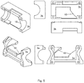
- Fig. 7 shows details of the locking mechanism when used for the table shown in fig. 6a and 6b .
- the arrows along the middle piece of the U-shaped table legs 9 indicate how the table legs are displaced perpendicular to the direction of rotation, i.e. in a direction parallel to the surface of the table top, during folding and un-folding of the table legs 9.
- Fig. 7 also shows an enlargement of the corner bearings 26 which are placed on each side of the locking mechanism.
- a first side of the L-shaped corner bearing 26 is fixed to the table top 25, this side of the L-shaped corner bearing 26 defines the distance between the lower surface of the table top 25 and the perifery of the circular table leg 9.
- the length of the second side of the L-shaped corner bearing defines the distance between the folded tables when they are stacked during storage in a folded state.
- the corner bearings also help stabilizing the table when the table is in the unfolded and locked use position.
Landscapes
- Pivots And Pivotal Connections (AREA)
Claims (16)
- Mécanisme de verrouillage à fixer à un dispositif ou à une partie de dispositif comprenant une première (1) et une deuxième (9) portion,- la première portion (1) est fixée de manière non détachable à une partie stationnaire (2) par l'intermédiaire d'une liaison articulée (5, 6) définissant un axe oscillant a1, la première portion (1) peut pivoter par rapport à la partie stationnaire (2) le long de l'axe oscillant a1 et présente au moins deux positions: une position de verrouillage et une position déverrouillée, la première portion (1) comprend:--- une partie en saillie (1a) s'étendant en direction de la deuxième portion (9) et ayant une première surface de contact (1b),--- une position de fixation pour un ressort (7) ou un système à ressort dont le ressort (7) ou le système à ressort force la première portion (1) dans la position verrouillée, lors de sollicitation du ressort (7), la première portion (1) est mise en position déverrouillée,--- un mécanisme de libération (1c, 1d) qui, lors de l'impact par l'utilisateur sollicite le ressort (7),- la deuxième portion (9) comprend une première partie en saillie (4) ayant une deuxième surface de contact (4a) et une deuxième partie saillante (14) ayant une troisième surface de contact (14a), la deuxième portion (9) peut être dans une position verrouillée et dans une position déverrouillée et, lorsqu'elle est dans la position verrouillée, la première surface de contact (1b) touche la deuxième surface de contact (4a), la deuxième portion (9) est située dans un palier (3, 3a, 3b) permettant la rotation entre les positions verrouillée et déverrouillée de la deuxième portion (9), et le palier (3, 3a, 3b) est fixe par rapport à la partie stationnaire (2), le palier (3, 3a, 3b) ou la partie stationnaire (2) ou une partie indépendante maintenue en position par la partie stationnaire (2) ou par le palier (3, 3a) présente une quatrième surface de contact (8a) et, lorsqu'elle est dans la position verrouillée, la troisième surface de contact (14a) de la deuxième portion (9) touche la quatrième surface de contact (8a), dans lequel la partie stationnaire (2) est un profilé fermé.
- Mécanisme de verrouillage selon la revendication 1, dans lequel le profilé est constitué de matériau extrudé.
- Mécanisme de verrouillage selon la revendication 1 ou 2, dans lequel la partie stationnaire (2) est constituée d'un matériau léger, par ex. aluminium.
- Mécanisme de verrouillage selon l'une quelconque des revendications précédentes, dans lequel la première portion (1) est au moins partiellement positionnée à l'intérieur de la partie stationnaire (2), et la partie stationnaire (2) est fixée à une partie d'un dispositif.
- Mécanisme de verrouillage selon l'une quelconque des revendications précédentes, dans lequel la partie stationnaire (2) est constituée par le dispositif ou une partie de celui-ci, telle qu'une surface d'un dessus de table ou d'une paroi ou d'un côté d'une étagère montée sur la paroi.
- Mécanisme de verrouillage selon l'une quelconque des revendications précédentes, dans lequel le mécanisme de libération est un bras de libération (1c, 1d) s'étendant dans une direction opposée à la partie en saillie (1b).
- Mécanisme de verrouillage selon l'une quelconque des revendications précédentes, dans lequel la partie du palier (3, 3a, 3b) ou la partie stationnaire (2) ou la partie indépendante maintenue en position par la partie stationnaire (2) ou par le palier (3, 3a) ayant la quatrième surface de contact (14b) est faite d'acier ou d'un matériau ayant une dureté d'indentation similaire, c'est-à-dire une capacité à résister à la déformation
- Mécanisme de verrouillage selon l'une quelconque des revendications précédentes, dans lequel le ressort (7) ou le système à ressort présente une deuxième position de fixation sur la partie stationnaire (2).
- Mécanisme de verrouillage selon l'une quelconque des revendications précédentes, dans lequel le ressort (7) ou le système à ressort présente une deuxième position de fixation sur la partie stationnaire (2) qui, par rapport à l'axe oscillant a1, est placée en regard de la partie en saillie (1a), et le ressort (7) est sollicité lorsqu'il est étendu, c'est-à-dire que le ressort (7) tire.
- Mécanisme de verrouillage selon l'une quelconque des revendications précédentes, dans lequel la première portion (1) peut être fixée de manière non détachable sur une surface d'un dessus de table, et la deuxième portion (9) comprend un ensemble de deux pattes de table qui peuvent pivoter entre une position verrouillée dans laquelle les pattes de table peuvent soutenir le dessus de table, et une position déverrouillée dans laquelle les pieds de table sont dans une position repliée.
- Mécanisme de verrouillage selon l'une quelconque des revendications précédentes, dans lequel le palier (3, 3a, 3b) fournit des moyens de guidage (10) fournissant un décalage dans une direction perpendiculaire à la direction de rotation de la deuxième portion (9) lorsque la deuxième portion (9) est pivotée à partir de la position verrouillée vers la position déverrouillée et les mêmes moyens de guidage ou des moyens de guidage secondaires fournissent un décalage dans la direction opposée lorsque la deuxième portion (9) est pivotée à partir de la position déverrouillée vers la position verrouillée.
- Mécanisme de verrouillage selon l'une quelconque des revendications précédentes, dans lequel une partie du palier (3a) fournit des moyens de guidage primaires (10) fournissant un décalage dans une direction à la fois perpendiculaire à la direction de rotation de la deuxième portion (9) et parallèle à la surface de fixation, lorsque la deuxième portion est amenée à partir de la position verrouillée vers la position déverrouillée, et une deuxième partie du palier (3b) fournit des moyens de guidage secondaires (10) fournissant un décalage dans la direction opposée lorsque la deuxième portion (9) est amenée à partir de la position déverrouillée vers la position verrouillée.
- Mécanisme de verrouillage selon la revendication 11 ou 12, dans lequel le moyen de guidage (10) comprend au moins deux surfaces inclinées (10) correspondant à chacune de leur surface respectivement de la première et de la deuxième partie en saillie (4).
- Mécanisme de verrouillage selon l'une quelconque des revendications précédentes, dans lequel le mécanisme de verrouillage comprend des moyens (6) pour ajuster la distance entre les première et deuxième surfaces de contact (1b, 4a) respectivement de la première (1) et de la deuxième (9) portion.
- Mécanisme de verrouillage selon l'une quelconque des revendications précédentes, dans lequel la liaison articulée (5, 6) comprend deux vis pointues (6) avec des têtes rondes formant une ligne, ladite ligne constituant l'axe oscillant a1.
- Mécanisme de verrouillage selon la revendication 15, dans lequel les têtes rondes des vis pointues (6) sont tournées vers la partie stationnaire (2), et chaque tête ronde s'adapte dans un évidement supérieur d'un boulon de vis (5) attaché à la partie stationnaire (2).
Priority Applications (2)
| Application Number | Priority Date | Filing Date | Title |
|---|---|---|---|
| DK13195480.2T DK2881007T3 (en) | 2013-12-03 | 2013-12-03 | Stopper |
| EP13195480.2A EP2881007B1 (fr) | 2013-12-03 | 2013-12-03 | Mécanisme de verrouillage |
Applications Claiming Priority (1)
| Application Number | Priority Date | Filing Date | Title |
|---|---|---|---|
| EP13195480.2A EP2881007B1 (fr) | 2013-12-03 | 2013-12-03 | Mécanisme de verrouillage |
Publications (2)
| Publication Number | Publication Date |
|---|---|
| EP2881007A1 EP2881007A1 (fr) | 2015-06-10 |
| EP2881007B1 true EP2881007B1 (fr) | 2017-11-22 |
Family
ID=49725010
Family Applications (1)
| Application Number | Title | Priority Date | Filing Date |
|---|---|---|---|
| EP13195480.2A Active EP2881007B1 (fr) | 2013-12-03 | 2013-12-03 | Mécanisme de verrouillage |
Country Status (2)
| Country | Link |
|---|---|
| EP (1) | EP2881007B1 (fr) |
| DK (1) | DK2881007T3 (fr) |
Families Citing this family (3)
| Publication number | Priority date | Publication date | Assignee | Title |
|---|---|---|---|---|
| USD895325S1 (en) | 2018-04-16 | 2020-09-08 | Playground Store Limited | Desktop with stowed legs |
| CN109996466B (zh) | 2018-04-16 | 2021-12-28 | 游乐场商店有限公司 | 桌子系统 |
| USD879514S1 (en) | 2018-04-16 | 2020-03-31 | Playground Store Limited | Desk |
Citations (3)
| Publication number | Priority date | Publication date | Assignee | Title |
|---|---|---|---|---|
| DE102007033742B3 (de) | 2007-07-18 | 2009-02-12 | Stechert Stahlrohrmöbel GmbH | Tisch mit einer Tischplatte und mit zwei Tischbein-Paaren |
| KR20100004791U (ko) | 2008-10-30 | 2010-05-11 | 노영철 | 절첩식 상다리 고정장치 |
| DE202011106673U1 (de) | 2011-10-12 | 2012-02-13 | Horst Hartmann | Dreh- und Verriegelungselement für Klapptische |
Family Cites Families (6)
| Publication number | Priority date | Publication date | Assignee | Title |
|---|---|---|---|---|
| JP4332197B1 (ja) * | 2008-03-07 | 2009-09-16 | 山田工業株式会社 | テーブル及びテーブルの脚支持構造 |
| DE202008005046U1 (de) | 2008-04-11 | 2008-07-03 | Design Ballendat Gmbh | Tisch mit verschwenkbarem Bügelfuß |
| DE102009011706A1 (de) * | 2009-03-09 | 2010-09-16 | Reinhold Thies Stanz- Und Rohrteile Gmbh | Beschlag |
| US8413594B2 (en) * | 2010-08-18 | 2013-04-09 | DSA International, Inc. | Folding leg latch assembly |
| CH704329A2 (de) * | 2011-01-13 | 2012-07-13 | Walter Gasser | Klappgestell. |
| DE202011101437U1 (de) * | 2011-06-03 | 2011-08-09 | Horst Hartmann | Arretierungs-und Verriegelungssystem für Klapptische |
-
2013
- 2013-12-03 DK DK13195480.2T patent/DK2881007T3/en active
- 2013-12-03 EP EP13195480.2A patent/EP2881007B1/fr active Active
Patent Citations (3)
| Publication number | Priority date | Publication date | Assignee | Title |
|---|---|---|---|---|
| DE102007033742B3 (de) | 2007-07-18 | 2009-02-12 | Stechert Stahlrohrmöbel GmbH | Tisch mit einer Tischplatte und mit zwei Tischbein-Paaren |
| KR20100004791U (ko) | 2008-10-30 | 2010-05-11 | 노영철 | 절첩식 상다리 고정장치 |
| DE202011106673U1 (de) | 2011-10-12 | 2012-02-13 | Horst Hartmann | Dreh- und Verriegelungselement für Klapptische |
Also Published As
| Publication number | Publication date |
|---|---|
| EP2881007A1 (fr) | 2015-06-10 |
| DK2881007T3 (en) | 2017-12-18 |
Similar Documents
| Publication | Publication Date | Title |
|---|---|---|
| US8960104B2 (en) | Table | |
| US8745922B1 (en) | Gate apparatus | |
| US6854304B2 (en) | Paddle lock | |
| US3643292A (en) | Automatically interlockable hinge fitting | |
| EP3344834B1 (fr) | Verrou à crochet avec éléments de liaison individuels | |
| US20080178778A1 (en) | Latch assembly with remote release | |
| US20100052339A1 (en) | Locker structure | |
| US20100175598A1 (en) | Table with swingable bow foot | |
| EP2881007B1 (fr) | Mécanisme de verrouillage | |
| US6929292B1 (en) | Lever lock system | |
| JP5168019B2 (ja) | 折畳み式テーブルの天板回動装置 | |
| GB2456697A (en) | Aircraft interior equipment support | |
| JP2012149838A (ja) | 冷蔵庫の棚装置及び冷蔵庫 | |
| US7913682B2 (en) | Barbeque grill having foldable stands | |
| CA2733555A1 (fr) | Dispositif de verrouillage abattant et charniere | |
| US6877806B2 (en) | Folding tray assembly | |
| US6958904B2 (en) | Rotating display mounting structure | |
| WO2020230310A1 (fr) | Accessoire d'articulation | |
| JP5080901B2 (ja) | 折畳み式テーブルの上アームユニット | |
| US8151416B2 (en) | Hinge with integral locking mechanism | |
| JP6769819B2 (ja) | ドアガードおよびドアガード装置 | |
| JP2006102146A (ja) | 椅子における座の前後摺動装置 | |
| JP7328758B2 (ja) | 折畳み式テーブル | |
| HK1133163A (en) | Table with swingable bow foot | |
| WO2013114224A2 (fr) | Verrou de poignée de porte à béquille |
Legal Events
| Date | Code | Title | Description |
|---|---|---|---|
| PUAI | Public reference made under article 153(3) epc to a published international application that has entered the european phase |
Free format text: ORIGINAL CODE: 0009012 |
|
| 17P | Request for examination filed |
Effective date: 20131203 |
|
| AK | Designated contracting states |
Kind code of ref document: A1 Designated state(s): AL AT BE BG CH CY CZ DE DK EE ES FI FR GB GR HR HU IE IS IT LI LT LU LV MC MK MT NL NO PL PT RO RS SE SI SK SM TR |
|
| AX | Request for extension of the european patent |
Extension state: BA ME |
|
| R17P | Request for examination filed (corrected) |
Effective date: 20151130 |
|
| RBV | Designated contracting states (corrected) |
Designated state(s): AL AT BE BG CH CY CZ DE DK EE ES FI FR GB GR HR HU IE IS IT LI LT LU LV MC MK MT NL NO PL PT RO RS SE SI SK SM TR |
|
| 17Q | First examination report despatched |
Effective date: 20160808 |
|
| GRAP | Despatch of communication of intention to grant a patent |
Free format text: ORIGINAL CODE: EPIDOSNIGR1 |
|
| INTG | Intention to grant announced |
Effective date: 20170424 |
|
| GRAS | Grant fee paid |
Free format text: ORIGINAL CODE: EPIDOSNIGR3 |
|
| GRAA | (expected) grant |
Free format text: ORIGINAL CODE: 0009210 |
|
| AK | Designated contracting states |
Kind code of ref document: B1 Designated state(s): AL AT BE BG CH CY CZ DE DK EE ES FI FR GB GR HR HU IE IS IT LI LT LU LV MC MK MT NL NO PL PT RO RS SE SI SK SM TR |
|
| REG | Reference to a national code |
Ref country code: GB Ref legal event code: FG4D |
|
| REG | Reference to a national code |
Ref country code: CH Ref legal event code: EP |
|
| REG | Reference to a national code |
Ref country code: FR Ref legal event code: PLFP Year of fee payment: 5 Ref country code: IE Ref legal event code: FG4D |
|
| REG | Reference to a national code |
Ref country code: AT Ref legal event code: REF Ref document number: 947573 Country of ref document: AT Kind code of ref document: T Effective date: 20171215 |
|
| REG | Reference to a national code |
Ref country code: DK Ref legal event code: T3 Effective date: 20171213 |
|
| REG | Reference to a national code |
Ref country code: DE Ref legal event code: R096 Ref document number: 602013029714 Country of ref document: DE |
|
| REG | Reference to a national code |
Ref country code: NL Ref legal event code: MP Effective date: 20171122 |
|
| REG | Reference to a national code |
Ref country code: LT Ref legal event code: MG4D |
|
| REG | Reference to a national code |
Ref country code: AT Ref legal event code: MK05 Ref document number: 947573 Country of ref document: AT Kind code of ref document: T Effective date: 20171122 |
|
| PG25 | Lapsed in a contracting state [announced via postgrant information from national office to epo] |
Ref country code: SE Free format text: LAPSE BECAUSE OF FAILURE TO SUBMIT A TRANSLATION OF THE DESCRIPTION OR TO PAY THE FEE WITHIN THE PRESCRIBED TIME-LIMIT Effective date: 20171122 Ref country code: ES Free format text: LAPSE BECAUSE OF FAILURE TO SUBMIT A TRANSLATION OF THE DESCRIPTION OR TO PAY THE FEE WITHIN THE PRESCRIBED TIME-LIMIT Effective date: 20171122 Ref country code: NL Free format text: LAPSE BECAUSE OF FAILURE TO SUBMIT A TRANSLATION OF THE DESCRIPTION OR TO PAY THE FEE WITHIN THE PRESCRIBED TIME-LIMIT Effective date: 20171122 Ref country code: NO Free format text: LAPSE BECAUSE OF FAILURE TO SUBMIT A TRANSLATION OF THE DESCRIPTION OR TO PAY THE FEE WITHIN THE PRESCRIBED TIME-LIMIT Effective date: 20180222 Ref country code: LT Free format text: LAPSE BECAUSE OF FAILURE TO SUBMIT A TRANSLATION OF THE DESCRIPTION OR TO PAY THE FEE WITHIN THE PRESCRIBED TIME-LIMIT Effective date: 20171122 Ref country code: FI Free format text: LAPSE BECAUSE OF FAILURE TO SUBMIT A TRANSLATION OF THE DESCRIPTION OR TO PAY THE FEE WITHIN THE PRESCRIBED TIME-LIMIT Effective date: 20171122 |
|
| PG25 | Lapsed in a contracting state [announced via postgrant information from national office to epo] |
Ref country code: RS Free format text: LAPSE BECAUSE OF FAILURE TO SUBMIT A TRANSLATION OF THE DESCRIPTION OR TO PAY THE FEE WITHIN THE PRESCRIBED TIME-LIMIT Effective date: 20171122 Ref country code: AT Free format text: LAPSE BECAUSE OF FAILURE TO SUBMIT A TRANSLATION OF THE DESCRIPTION OR TO PAY THE FEE WITHIN THE PRESCRIBED TIME-LIMIT Effective date: 20171122 Ref country code: GR Free format text: LAPSE BECAUSE OF FAILURE TO SUBMIT A TRANSLATION OF THE DESCRIPTION OR TO PAY THE FEE WITHIN THE PRESCRIBED TIME-LIMIT Effective date: 20180223 Ref country code: BG Free format text: LAPSE BECAUSE OF FAILURE TO SUBMIT A TRANSLATION OF THE DESCRIPTION OR TO PAY THE FEE WITHIN THE PRESCRIBED TIME-LIMIT Effective date: 20180222 Ref country code: LV Free format text: LAPSE BECAUSE OF FAILURE TO SUBMIT A TRANSLATION OF THE DESCRIPTION OR TO PAY THE FEE WITHIN THE PRESCRIBED TIME-LIMIT Effective date: 20171122 Ref country code: HR Free format text: LAPSE BECAUSE OF FAILURE TO SUBMIT A TRANSLATION OF THE DESCRIPTION OR TO PAY THE FEE WITHIN THE PRESCRIBED TIME-LIMIT Effective date: 20171122 |
|
| PG25 | Lapsed in a contracting state [announced via postgrant information from national office to epo] |
Ref country code: SK Free format text: LAPSE BECAUSE OF FAILURE TO SUBMIT A TRANSLATION OF THE DESCRIPTION OR TO PAY THE FEE WITHIN THE PRESCRIBED TIME-LIMIT Effective date: 20171122 Ref country code: CZ Free format text: LAPSE BECAUSE OF FAILURE TO SUBMIT A TRANSLATION OF THE DESCRIPTION OR TO PAY THE FEE WITHIN THE PRESCRIBED TIME-LIMIT Effective date: 20171122 Ref country code: CY Free format text: LAPSE BECAUSE OF FAILURE TO SUBMIT A TRANSLATION OF THE DESCRIPTION OR TO PAY THE FEE WITHIN THE PRESCRIBED TIME-LIMIT Effective date: 20171122 Ref country code: EE Free format text: LAPSE BECAUSE OF FAILURE TO SUBMIT A TRANSLATION OF THE DESCRIPTION OR TO PAY THE FEE WITHIN THE PRESCRIBED TIME-LIMIT Effective date: 20171122 |
|
| REG | Reference to a national code |
Ref country code: CH Ref legal event code: PL |
|
| REG | Reference to a national code |
Ref country code: DE Ref legal event code: R026 Ref document number: 602013029714 Country of ref document: DE |
|
| PLBI | Opposition filed |
Free format text: ORIGINAL CODE: 0009260 |
|
| PG25 | Lapsed in a contracting state [announced via postgrant information from national office to epo] |
Ref country code: RO Free format text: LAPSE BECAUSE OF FAILURE TO SUBMIT A TRANSLATION OF THE DESCRIPTION OR TO PAY THE FEE WITHIN THE PRESCRIBED TIME-LIMIT Effective date: 20171122 Ref country code: PL Free format text: LAPSE BECAUSE OF FAILURE TO SUBMIT A TRANSLATION OF THE DESCRIPTION OR TO PAY THE FEE WITHIN THE PRESCRIBED TIME-LIMIT Effective date: 20171122 Ref country code: SM Free format text: LAPSE BECAUSE OF FAILURE TO SUBMIT A TRANSLATION OF THE DESCRIPTION OR TO PAY THE FEE WITHIN THE PRESCRIBED TIME-LIMIT Effective date: 20171122 Ref country code: IT Free format text: LAPSE BECAUSE OF FAILURE TO SUBMIT A TRANSLATION OF THE DESCRIPTION OR TO PAY THE FEE WITHIN THE PRESCRIBED TIME-LIMIT Effective date: 20171122 |
|
| PLAX | Notice of opposition and request to file observation + time limit sent |
Free format text: ORIGINAL CODE: EPIDOSNOBS2 |
|
| 26 | Opposition filed |
Opponent name: FLOKK AS Effective date: 20180803 |
|
| REG | Reference to a national code |
Ref country code: IE Ref legal event code: MM4A |
|
| PG25 | Lapsed in a contracting state [announced via postgrant information from national office to epo] |
Ref country code: MT Free format text: LAPSE BECAUSE OF NON-PAYMENT OF DUE FEES Effective date: 20171203 Ref country code: LU Free format text: LAPSE BECAUSE OF NON-PAYMENT OF DUE FEES Effective date: 20171203 |
|
| REG | Reference to a national code |
Ref country code: FR Ref legal event code: PLFP Year of fee payment: 6 |
|
| REG | Reference to a national code |
Ref country code: BE Ref legal event code: MM Effective date: 20171231 |
|
| PG25 | Lapsed in a contracting state [announced via postgrant information from national office to epo] |
Ref country code: IE Free format text: LAPSE BECAUSE OF NON-PAYMENT OF DUE FEES Effective date: 20171203 |
|
| PG25 | Lapsed in a contracting state [announced via postgrant information from national office to epo] |
Ref country code: SI Free format text: LAPSE BECAUSE OF FAILURE TO SUBMIT A TRANSLATION OF THE DESCRIPTION OR TO PAY THE FEE WITHIN THE PRESCRIBED TIME-LIMIT Effective date: 20171122 Ref country code: BE Free format text: LAPSE BECAUSE OF NON-PAYMENT OF DUE FEES Effective date: 20171231 Ref country code: LI Free format text: LAPSE BECAUSE OF NON-PAYMENT OF DUE FEES Effective date: 20171231 Ref country code: CH Free format text: LAPSE BECAUSE OF NON-PAYMENT OF DUE FEES Effective date: 20171231 |
|
| PLBB | Reply of patent proprietor to notice(s) of opposition received |
Free format text: ORIGINAL CODE: EPIDOSNOBS3 |
|
| PG25 | Lapsed in a contracting state [announced via postgrant information from national office to epo] |
Ref country code: HU Free format text: LAPSE BECAUSE OF FAILURE TO SUBMIT A TRANSLATION OF THE DESCRIPTION OR TO PAY THE FEE WITHIN THE PRESCRIBED TIME-LIMIT; INVALID AB INITIO Effective date: 20131203 Ref country code: MC Free format text: LAPSE BECAUSE OF FAILURE TO SUBMIT A TRANSLATION OF THE DESCRIPTION OR TO PAY THE FEE WITHIN THE PRESCRIBED TIME-LIMIT Effective date: 20171122 |
|
| PLBP | Opposition withdrawn |
Free format text: ORIGINAL CODE: 0009264 |
|
| PLBD | Termination of opposition procedure: decision despatched |
Free format text: ORIGINAL CODE: EPIDOSNOPC1 |
|
| REG | Reference to a national code |
Ref country code: DE Ref legal event code: R100 Ref document number: 602013029714 Country of ref document: DE |
|
| PG25 | Lapsed in a contracting state [announced via postgrant information from national office to epo] |
Ref country code: MK Free format text: LAPSE BECAUSE OF FAILURE TO SUBMIT A TRANSLATION OF THE DESCRIPTION OR TO PAY THE FEE WITHIN THE PRESCRIBED TIME-LIMIT Effective date: 20171122 |
|
| PLBM | Termination of opposition procedure: date of legal effect published |
Free format text: ORIGINAL CODE: 0009276 |
|
| 27C | Opposition proceedings terminated |
Effective date: 20191026 |
|
| PG25 | Lapsed in a contracting state [announced via postgrant information from national office to epo] |
Ref country code: TR Free format text: LAPSE BECAUSE OF FAILURE TO SUBMIT A TRANSLATION OF THE DESCRIPTION OR TO PAY THE FEE WITHIN THE PRESCRIBED TIME-LIMIT Effective date: 20171122 |
|
| PG25 | Lapsed in a contracting state [announced via postgrant information from national office to epo] |
Ref country code: PT Free format text: LAPSE BECAUSE OF FAILURE TO SUBMIT A TRANSLATION OF THE DESCRIPTION OR TO PAY THE FEE WITHIN THE PRESCRIBED TIME-LIMIT Effective date: 20171122 |
|
| PG25 | Lapsed in a contracting state [announced via postgrant information from national office to epo] |
Ref country code: AL Free format text: LAPSE BECAUSE OF FAILURE TO SUBMIT A TRANSLATION OF THE DESCRIPTION OR TO PAY THE FEE WITHIN THE PRESCRIBED TIME-LIMIT Effective date: 20171122 Ref country code: IS Free format text: LAPSE BECAUSE OF FAILURE TO SUBMIT A TRANSLATION OF THE DESCRIPTION OR TO PAY THE FEE WITHIN THE PRESCRIBED TIME-LIMIT Effective date: 20180322 |
|
| REG | Reference to a national code |
Ref country code: DE Ref legal event code: R082 Ref document number: 602013029714 Country of ref document: DE Representative=s name: ZACCO LEGAL RECHTSANWALTSGESELLSCHAFT MBH, DE |
|
| PGFP | Annual fee paid to national office [announced via postgrant information from national office to epo] |
Ref country code: DE Payment date: 20241119 Year of fee payment: 12 |
|
| PGFP | Annual fee paid to national office [announced via postgrant information from national office to epo] |
Ref country code: DK Payment date: 20241015 Year of fee payment: 12 |
|
| PGFP | Annual fee paid to national office [announced via postgrant information from national office to epo] |
Ref country code: GB Payment date: 20241018 Year of fee payment: 12 |
|
| PGFP | Annual fee paid to national office [announced via postgrant information from national office to epo] |
Ref country code: FR Payment date: 20241021 Year of fee payment: 12 |
|
| REG | Reference to a national code |
Ref country code: DE Ref legal event code: R082 Ref document number: 602013029714 Country of ref document: DE |