EP2880720B1 - Elektrische einrichtung mit explosionsgeschützter steckverbindung - Google Patents
Elektrische einrichtung mit explosionsgeschützter steckverbindung Download PDFInfo
- Publication number
- EP2880720B1 EP2880720B1 EP13735308.2A EP13735308A EP2880720B1 EP 2880720 B1 EP2880720 B1 EP 2880720B1 EP 13735308 A EP13735308 A EP 13735308A EP 2880720 B1 EP2880720 B1 EP 2880720B1
- Authority
- EP
- European Patent Office
- Prior art keywords
- contact
- counter
- contacts
- mating
- type
- Prior art date
- Legal status (The legal status is an assumption and is not a legal conclusion. Google has not performed a legal analysis and makes no representation as to the accuracy of the status listed.)
- Active
Links
Images


Classifications
-
- H—ELECTRICITY
- H01—ELECTRIC ELEMENTS
- H01R—ELECTRICALLY-CONDUCTIVE CONNECTIONS; STRUCTURAL ASSOCIATIONS OF A PLURALITY OF MUTUALLY-INSULATED ELECTRICAL CONNECTING ELEMENTS; COUPLING DEVICES; CURRENT COLLECTORS
- H01R13/00—Details of coupling devices of the kinds covered by groups H01R12/70 or H01R24/00 - H01R33/00
- H01R13/66—Structural association with built-in electrical component
- H01R13/70—Structural association with built-in electrical component with built-in switch
- H01R13/703—Structural association with built-in electrical component with built-in switch operated by engagement or disengagement of coupling parts, e.g. dual-continuity coupling part
- H01R13/7036—Structural association with built-in electrical component with built-in switch operated by engagement or disengagement of coupling parts, e.g. dual-continuity coupling part the switch being in series with coupling part, e.g. dead coupling, explosion proof coupling
-
- H—ELECTRICITY
- H01—ELECTRIC ELEMENTS
- H01R—ELECTRICALLY-CONDUCTIVE CONNECTIONS; STRUCTURAL ASSOCIATIONS OF A PLURALITY OF MUTUALLY-INSULATED ELECTRICAL CONNECTING ELEMENTS; COUPLING DEVICES; CURRENT COLLECTORS
- H01R13/00—Details of coupling devices of the kinds covered by groups H01R12/70 or H01R24/00 - H01R33/00
- H01R13/66—Structural association with built-in electrical component
- H01R13/70—Structural association with built-in electrical component with built-in switch
- H01R13/703—Structural association with built-in electrical component with built-in switch operated by engagement or disengagement of coupling parts, e.g. dual-continuity coupling part
-
- H—ELECTRICITY
- H01—ELECTRIC ELEMENTS
- H01R—ELECTRICALLY-CONDUCTIVE CONNECTIONS; STRUCTURAL ASSOCIATIONS OF A PLURALITY OF MUTUALLY-INSULATED ELECTRICAL CONNECTING ELEMENTS; COUPLING DEVICES; CURRENT COLLECTORS
- H01R13/00—Details of coupling devices of the kinds covered by groups H01R12/70 or H01R24/00 - H01R33/00
- H01R13/46—Bases; Cases
- H01R13/53—Bases or cases for heavy duty; Bases or cases for high voltage with means for preventing corona or arcing
Definitions
- the invention relates to an electrical device with a connector for the electrical connection of several components of the electrical device.
- US 4166664 writes a connector device with high-voltage contacts and low-voltage contacts.
- EP 0 314 949 A1 and DE 10 2006 016 137 A1 reveal connectors with different lengths of contact pins that belong to different circuits.
- EP 1 202 424 A2 discloses an arrangement with a distribution element for distributing electrical circuits in a hazardous area disclosed.
- the distributor element has pins and sockets. Both intrinsically safe and non-intrinsically safe field devices can be connected to the distributor.
- the sockets are coded on the distributor element, for example at different depths, so that an unambiguous assignment of intrinsically safe and non-intrinsically safe connections is ensured.
- the second type of protection is preferably the type of protection Ex e.
- the first type of protection is preferably the degree of protection Ex d or Ex i.
- the contact group comprises multiple contact / mating contact pairings. These can be arranged in branches of the electrical circuit connected in parallel to each other. Also, they are preferably each associated with individual current limiting circuits. The structural complexity of such a connector remains low. The explosion protection is realized electrically.
- the current limiting circuits may be associated with the connector assembly. An intervention in the Electronics of the circuit to be connected is not required.
- the contact / mating contact pairings in particular, if the degree of protection Ex i is provided, voltage limiting circuits can be assigned. These prevent sparking at the contacts, which are designed, for example, in the type of protection Ex i.
- This embodiment is particularly suitable for circuits having one or more inductive components in the circuit.
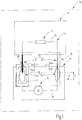
- an electrical device 10 is schematically illustrated, which is operable in a potentially explosive environment.
- the electrical device 10 comprises at least two components 11, 12, which cooperate electrically.
- the component 11 may contain one or more electrical consumers, such as, for example, light sources, motors, sounders or other electrical components or apparatus, such as computers or the like. All such consumers are in FIG. 1 symbolized by a resistor 13. Its impedance can be purely ohmic, purely reactive or complex.
- the first component 11 may include non-illustrated power or voltage sources.
- the second component 12 contains at least one voltage source 14, which feeds the electrical load 13.
- the voltage source 14 may be of any suitable type. It may be formed, for example, as a rechargeable battery, as a power supply, as a primary battery, as a supercapacitor or as another memory.
- the second component 12 may include a plurality of such voltage sources 14 in series or parallel connection.
- the second component 12 may include electrical loads.
- the two components 11, 12 are electrically connected to each other.
- a connector device 15 which in FIG. 1 is symbolized by a long / short dashed square.
- the connector device 15 includes a contact assembly 16, which comprises at least two Kohntaktmaschine 17, 18.
- the contact group 17 comprises at least one contact 17a or several such contacts.
- the contact 17a (and optionally further to the same contact group 17 associated contacts) may be formed, for example, as plug contacts or alternatively as a socket contacts.
- the second contact group 18 comprises at least one contact 18a or optionally also a plurality of contacts.
- To the connector device 15 also includes a mating contact assembly 19 which includes a first mating contact group 20 and a second mating contact group 21.
- the first mating contact group 20 has a mating contact 20a and possibly further mating contacts.
- the second mating contact group 21 has at least one mating contact 21a and possibly further mating contacts.
- the mating contacts 20a, 21a of the two mating contact groups and optionally further mating contacts belonging to the groups can be designed as plugs or sockets.
- the contact 17a and the mating contact 20a together form a contact / mating contact pairing 22.
- the contact 18a and the mating contact 21a together form a contact / mating contact mating 23.
- the contact / mating contact pairings 22, 23 form the forward conductor and the return conductor, which electrically connect a first section 25 to a second section 26 in a circuit 24.
- the first section 25 is arranged in the first component 11.
- the section 25 contains the electrical load 13.
- the second section 26 is arranged in the second component 12 and contains the source 14.
- the plug connector 15 fulfills a high type of protection, such as, for example, Ex d or Ex i.
- a high type of protection such as, for example, Ex d or Ex i.
- the contact / WhitneyPaarung here the pairing 22
- the contact / WhitneyPaarung which receives the last electrical contact when connecting the connector 15 and at the same time is the one who first disconnects the electrical current path when disconnecting, in the first degree of protection, here, for example.
- Ex d educated is the one who first disconnects the electrical current path when disconnecting, in the first degree of protection, here, for example.
- the type of protection Ex d is achieved, for example, by an enclosure of the mating contact group 20 or of the mating contact 20 a, which defines a gap 28 with the contact group 17 or the contact 17 a, which is so long and so narrow that, in the case of an explosion within the housing 27 From the gap 28 escape neither flames nor glowing particles.
- the other contact / mating contact pairing 23, however, is executed in the second type of protection, for example.
- It is considered to be static electrical contact, which only closes or disconnects when it is de-energized.
- the currentlessness is effected when closing by the lead V and when opening by the lag N, with which the contact 18a operates in comparison to the contact 17a.
- the lead V and the lag N can be achieved in the simplest case by a length difference of the contacts 17a, 18a.
- a position or length difference of the mating contacts 20a, 21a may be provided.
- the premature closure of the contact / mating pairing 23 and the lagging opening thereof may alternatively be achieved by other means.
- the connector 15 may have other means to allow the electrical contact between the contact 17a and the mating contact 20a always only when the contact 18a and the mating contact 21a are already in secure contact. These means can also be provided to secure the contact 17a and the mating contact 20a disconnect before the contact 18a and the mating contact 21a separate.
- insulating elements may be provided for this purpose, which move the contact 17a and the contact 20a in a direction other than the insertion direction (eg transversely thereto) and thus close or disconnect, if the connector is to be made or disconnected.
- the device 10 works as follows:
- the connector device 15 When the components 11, 12 are provided, the connector device 15 is initially in a disconnected state. Now, if the contact assembly 16 is connected to the mating contact arrangement 19 by being moved towards each other, first closes the contact / mating contact pairing 23. This takes place in the de-energized state, because the circuit 24 is not yet closed. The circuit 24 closes as soon as the contact 17a is inserted into the housing 27 and comes within contact with the mating contact 20a. This may possibly cause a spark that ignites in the housing 27 located ignitable mixture. The enclosure 27 is sized to withstand the resulting explosion. Occurring overpressure can be reduced by the gap 28, wherein the length and small width of the gap 28 prevent the escape of flames or glowing particles. Likewise, the conditions when a spark occurs within the housing 27 when disconnecting the connector means 15.
- FIG. 2 illustrates a modified embodiment of the device 10.
- the above description is based on the already introduced reference numerals accordingly.
- the consumer 13 and the voltage source 14 are symbolically arranged by blocks. These may include multiple or many electrical or electronic components including current and voltage sources of ohmic elements in reactive elements or the like.
- the contact / mating contact mating 23 may include a plurality of contacts 18a, 18b and mating contacts 21a, 21b. These are electrically connected in parallel. Preferably, they are arranged on both sides of the contact / mating contact pairing 22. This provides protection against skewing when pulling and plugging. By an integrated or externally mounted mechanical guidance of the part to be inserted an inclination is prevented. If the contacts 18a, 18b and mating contacts 21a, 21b arranged at different opposite sides of the contact / mating contact pairing 22, can also be dispensed with a parallel guide, because even with inclined position of the corresponding connector parts a safe forward or lag the contacts 18a, 18b is sheared.
- the contact / mating contact pairing 22 is designed in degree of protection Ex d.
- the other contact / mating contact pairing 23 is carried out in the protection Ex e when plugging before and when pulling lagging.
- the circuit is safely disconnected when opening via the Ex d contact before the Ex e connection is disconnected.
- the contacts and mating contacts can also be executed several times and connected in parallel. This applies to the Ex e contacts as well as to the Ex d contacts.
- FIG. 3 remove Another variant of the combination of different types of protection can be according to the embodiment FIG. 3 remove.
- the contacts and mating contacts are subject to the type of protection Ex i. the contact mating contact pair 23 is in turn carried out in the type of protection Ex e
- the circuit 24 is, as far as it leads via the contacts 17 a to c and mating contacts 20 a to c, divided into mutually parallel branches 29, 30, 31. In these branches, current limiting devices 33 to 38 are provided at least in one of the components 11, 12, preferably in both.
- Such current limiting circuits can be constructed with transistors or other electronic components or integrated circuits that flow through them Monitor current and reduce if necessary.
- the principle lies in the fact that one of the conductors (forward conductor or return conductor) is guided in multiple poles over several Ex i contacts.
- the circuit 24 is divided into several intrinsically safe circuits.
- the Ex i contacts take over the activation of the circuit before the separation. Regardless of the degree of protection Ex i for the contact / mating contact arrangement 22, the components 11, 12 may also be formed completely or partially encapsulated.
- a voltage limiting device 39 may be provided which limits the voltages occurring at the Ex i contacts of the contact / mating contact pairing 22.
- this can be done by voltage limiting diodes, for example Z-diodes 40, 41, 42, which are connected to the branches 29, 30, 31 and which are connected to a common ground potential.
- the connection point of the zener diodes 40 to 42 can also be connected via a contact / counter contact pairing 46 to a suitable point of the circuit 24 in the respective other component, here the component 12.
- the Zener diodes 40 to 42 may be preceded by resistors 43, 44, 45, in order to limit the current that occurs. Otherwise, the previous description applies accordingly.
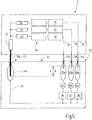
- the embodiment according to FIG. 4 be modified so that the voltage source 14 may be divided into individual voltage sources 14a, 14c to be formed.
- the circuit 24 is divided into individual Ex i circuits in different branches 29, 30, 31. The number of these individual branches results from the desired current flowing through the load 13 and the current load provided at each contact 17a-c.
- the contact / mating contact pairing 23 is preferably in turn an Ex e contact. The previous description otherwise applies accordingly.
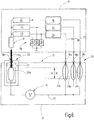
- FIG. 6 illustrates a modified embodiment in which a plurality of designed according to the ignition protection Ex i contact / mating contact pairings 23 with a designed according to the type of protection Ex d contact / mating contact pairing 23 cooperates.
- the switching contact here is the contact against contact pair 22. This is provided with the housing 27, which provides the explosion protection.
- the arranged in the branches 29, 39, 31 contact / mating contact pairings 23 are the leading during insertion and trailing when pulling contact pairings. They are current limiting devices 33 to 35 before and / or downstream. In addition, a voltage limiting device 39 may be provided.
- the circuit 24 is divided into several intrinsically safe circuits or branches 29 to 31.
- one of the conductors forward conductor or return conductor
- the other conductor is routed via one or more contact / counter contact pairings designed according to Ex d criteria.
- a current and / or a voltage limitation can be provided both in the component 11 and additionally or alternatively in the component 12.
- the voltage limiting device 39 can be supported on internal ground circuits on the ground.
- a connection modeled on FIG. 4 be provided. It may be the two components 11, 12 completely or partially encapsulated (eg Protection type Ex d or Ex m) may be formed.
- All embodiments with multiple contacts 17a-c or 18a-c, in particular after Figures 5 and 6 could be used to design a bus system.
- the respective contacts 17a-17c ( FIG. 5 ) or 18a - 18c ( Figure 6) may be formed as bus lines.
- the voltage source 14 may be housed in the component 11.
- the module 12 or a plurality of parallel modules 12 can then be plugged onto the bus lines.
- the contacts 20a-20c or 21a-21c as bus lines.
- one or more components 11 can be attached to these bus lines belonging to the module 12.
- the bus lines may be flexible or inflexible insulated or bare lines.
- contact / mating contact pairings 22, 23 which have juxtaposed, parallel aligned contacts 17, 18 and mating contacts 20, 21.
- the contact / mating mating 23 may form the Ex d enclosure for the mating / mating pair 22 (and optionally further, e.g., 46).
- a connector device 15 which serves to open and close a circuit 24.
- the connector device 15 includes at least two contact / mating contact pairings 22, 23, which are designed in different types of protection. At least one of the two Contact / mating pairing is designed to separate the current passing through them without causing an explosion. (Type of protection Ex d or Ex i).
- the other contact / mating contact pairing 23 opens and closes when de-energized. It can therefore be designed in the second type of protection, for example Ex e.
Landscapes
- Details Of Connecting Devices For Male And Female Coupling (AREA)
Description
- Die Erfindung betrifft eine elektrische Einrichtung mit einem Steckverbinder zur elektrischen Verbindung mehrerer Komponenten der elektrischen Einrichtung.
- Für explosionsgeschützte elektrische Betriebsmittel ist es bekannt, Steckverbinder vorzusehen, die in explosionsgefährdeten Bereichen eingesetzt werden können. Dazu schlägt die
EP 1 638 173 A2 Steckverbinder vor, die mehrere Kontaktstifte aufweisen. Einer der Kontaktstifte dient zur Kontaktierung eines Überwachungsleiters. Dieser Kontaktstift ist kürzer ausgeführt als die anderen Kontaktstifte, so dass er beim Herstellen der Steckverbindung als letzter kontaktiert und beim Trennen der Steckverbindung als erster trennt. An dem Überwachungsleiter liegt eine Spannung an, die unter der Mindestzündspannung liegt. Somit kann beim Öffnen und Schließen der Kontaktstelle kein Zündfunken entstehen. Über den Überwachungsleiter wird die Stromzufuhr zu und von den anderen längeren Kontaktstiften zu- und abgeschaltet. Dadurch kann sichergestellt werden, dass die anderen längeren Kontaktstifte immer in strom- und spannungslosen Zustand in Kontakt mit den zugeordneten Buchsen kommen. Die Kombination eines der Explosionsschutzart Ex i entsprechenden Überwachungsleiters mit anderen Kontakten, die nur im stromlosen Zustand geschlossen oder getrennt werden, setzt zusätzliche Schalter in den angeschlossenen Komponenten voraus. - Weiter offenbart die
DE 20 2005 010 927 U1 einen explosionsgeschützten Steckverbinder der Zündschutzart druckfeste Kapselung (Ex d). Diese ist so aufgebaut, dass die druckfeste Kapselung erhalten bleibt, bis alle Kontakte getrennt sind. - Explosionsschutz durch druckfeste Kapselung aller Kontakte führt zu einem großen konstruktiven und baulichen Aufwand.
-
DE 198 38 492 A1 beschreibt eine explosionsgeschützte Steckverbindungsanordnung mit zwei Steckverbinderleisten, die in zusammengestecktem Zustand eine elektrische Verbindung zwischen einer Stromquelle und einem Verbraucher herstellen, wobei eine Schaltungsanordnung mit gesteuerten Schaltern vorhanden ist, die einen Hauptstromkreis von der Stromquelle zum Verbraucher trennen und verbinden können und über einen Steuerstromkreis angesteuert werden. Beim Verbinden der Steckverbinderleisten werden zunächst die Kontakte des Hauptstromkreises geschlossen, so dass die gesteuerten Schalter in einem trennenden Zustand verbleiben, bis auch die Kontakte des Steuerstromkreises geschlossen werden und die Schalter in ihren leitenden Zustand umschalten können. -
US 4166664 schreibt eine Steckverbindungseinrichtung mit Hochvoltkontakten und Niedervoltkontakten. - Die aus
US 2943216 bekannte Steckverbindungseinrichtung hat zwei Steuerkontakte, die zu einem vom Hauptstromkreis separaten Steuerstromkreis gehören. Ein ansteuerbarer Schalter hat eine Steuerspule im Steuerstromkreis zur Betätigung eines Kontakts im Hauptstromkreis. Bei getrennter Steckverbindung ist die Steuerspule nicht bestromt und der Kontakt trennt den Hauptstromkreis. -
EP 0 314 949 A1 undDE 10 2006 016 137 A1 offenbaren Steckverbindungen mit unterschiedlich langen Kontaktstiften, die zu unterschiedlichen Stromkreisen gehören. - Aus
EP 1 202 424 A2 ist eine Anordnung mit einem Verteilerelement zur Verteilung elektrischer Stromkreise in einem explosionsgefährdeten Bereich offenbart. Das Verteilerelement weist Stifte und Buchsen auf. Es können sowohl eigensichere, als auch nicht eigensichere Feldgeräte an den Verteiler angeschlossen werden. Um den korrekten Anschluss sicherzustellen, sind die Buchsen am Verteilerelement kodiert, beispielsweise unterschiedlich tief, so dass eine eindeutige Zuordnung von eigensicheren und nicht eigensicheren Anschlüssen sichergestellt ist. - Es ist Aufgabe der Erfindung, eine explosionsgeschützte elektrische Einrichtung anzugeben, die mit geringem Aufwand auskommt und vielseitig einsetzbar ist.
- Diese Aufgabe wird mit der elektrischen Einrichtung nach Anspruch 1 gelöst:
- Bei der erfindungsgemäßen elektrischen Einrichtung ist ein Steckverbinder zur elektrischen Verbindung zweier Komponenten der elektrischen Einrichtung vorgesehen. Der Steckverbinder dient der Verbindung von zwei Abschnitten eines elektrischen Stromkreises, wobei der eine Abschnitt in einer Komponente der elektrischen Einrichtung und der andere Abschnitt in der anderen Komponente der elektrischen Einrichtung angeordnet ist. Die beiden Abschnitte bilden gemeinsam einen elektrischen Stromkreis. Der Steckverbinder umfasst eine Kontaktanordnung und eine Gegenkontaktanordnung. Die Kontaktanordnung umfasst wenigstens zwei Kontaktgruppen, eine für den Hinleiter und eine von dem Rückleiter. Jede Kontaktgruppe umfasst mindestens einen oder auch mehrere Kontakte. Ebenso umfasst die Gegenkontaktanordnung wenigstens zwei Gegenkontaktgruppen. Jede Gegenkontaktgruppe umfasst mindestens einen, gegebenenfalls auch mehrere Gegenkontakte. Die Kontakte und die Gegenkontakte können wahlweise als Steckstift oder sonstige sowie als Buchsenkontakt oder sonstiger Gegenkontakt ausgebildet sein. Die Kontakte und Gegenkontakte bilden Kontakt/Gegenkontakt-Paarungen. Erfindungsgemäß ist hier vorgesehen, dass die Kontakt/Gegenkontakt-Paarungen des Hinleiters und die Kontakt/Gegenkontakt-Paarungen des Rückleiters unterschiedliche Zündschutzarten aufweisen. Dies obwohl die Kontakt/Gegenkontakt-Paarungen des Hinleiters und des Rückleiters vorzugsweise vom gleichen Laststrom durchflossen sind. Die Kontakt/Gegenkontakt-Gruppen weisen jedoch unterschiedliche Erstberührungspositionen auf. Diejenige Kontakt/Gegenkontakt-Gruppe, die beim Zusammenführen des Steckverbinders eine spätere Kontaktgabe verzeichnet und beim Trennen des Steckverbinders früher trennt, weist eine erste Schutzart auf als die andere Kontakt/Gegenkontakt-Gruppe. Damit wirkt die später berührende und früher trennende Kontakt/Gegenkontakt-Gruppe (mit der ersten Schutzart) als explosionsgeschützter Trennschalter für die verbleibende andere Kontakt/Gegenkontakt-Gruppe mit anderer (zweiter).
- Die zweite Zündschutzart ist vorzugsweise die Schutzart Ex e. Die erste Zündschutzart ist vorzugsweise die Schutzart Ex d oder Ex i. Im Falle der Zündschutzart Ex d wird es bevorzugt, lediglich einen oder wenige Kontakte in dieser Schutzart auszuführen. In der Zündschutzart Ex i wird es bevorzugt, wenn die Kontaktgruppe mehrere Kontakt/Gegenkontakt-Paarungen umfasst. Diese können in zueinander parallel geschalteten Zweigen des elektrischen Stromkreises angeordnet sein. Auch sind ihnen vorzugsweise jeweils individuelle Strombegrenzungsschaltungen zugeordnet. Der bauliche Aufwand eines solchen Steckverbinders bleibt gering. Der Explosionsschutz wird elektrisch realisiert. Die Strombegrenzungsschaltungen können der Steckverbinderanordnung zugeordnet werden. Ein Eingriff in die Elektronik des zu verbindenden Stromkreises ist nicht erforderlich.
- Außerdem ist bei keiner der vorgesehenen Ausführungsformen ein zusätzlicher Überwachungsleiter erforderlich.
- Ergänzend zu den Strombegrenzungsschaltungen können den Kontakt/Gegenkontakt-Paarungen, insbesondere, wenn die Schutzart Ex i vorgesehen ist, Spannungsbegrenzungsschaltungen zugeordnet werden. Diese verhindern Funkenbildung an den Kontakten, die beispielsweise in der Zündschutzart Ex i ausgeführt sind. Diese Ausführungsform eignet sich besonders für Schaltungen, die in dem Stromkreis eine oder mehrere induktive Bauelemente aufweisen.
- Weiter Einzelheiten vorteilhafter Ausführungsformen der Erfindung sind Gegenstand der Ansprüche, der Beschreibung oder der Zeichnung. Es zeigen:
-
Figur 1 Eine erfindungsgemäße Einrichtung, in aufs äußerste schematisierter Darstellung. -
Figur 2 bis 6 weitere beispielhafte alternative Ausführungsformen der erfindungsgemäßen Einrichtung jeweils, in schematisierter Blockschaltbilddarstellung. - In
Figur 1 ist eine elektrische Einrichtung 10 schematisch veranschaulicht, die in explosionsgefährdeter Umgebung betreibbar ist. Die elektrische Einrichtung 10 umfasst mindestens zwei Komponenten 11, 12, die elektrisch zusammenwirken. Beispielsweise kann die Komponente 11 einen oder mehrere elektrische Verbraucher enthalten, wie bspw. Lichtquellen, Motoren, Schallgeber oder sonstige elektrische Bauelemente oder Apparaturen, wie z.B. Rechner oder dergleichen. Alle solche Verbraucher sind inFigur 1 durch einen Widerstand 13 symbolisiert. Dessen Impedanz kann rein ohmsch, rein reaktiv oder komplex sein. Außerdem kann die erste Komponente 11 nicht weiter veranschaulichte Strom- oder Spannungsquellen enthalten. - Die zweite Komponente 12 enthält mindestens eine Spannungsquelle 14, die den elektrischen Verbraucher 13 speist. Die Spannungsquelle 14 kann jede geeignete Bauart haben. Sie kann bspw. als Akkumulator, als Netzteil, als Primärbatterie, als Superkondensator oder als sonstiger Speicher ausgebildet sein. Die zweite Komponente 12 kann mehrere solcher Spannungsquellen 14 in Reihen- oder Parallelschaltung enthalten. Außerdem kann die zweite Komponente 12 elektrische Verbraucher enthalten.
- Um den Verbraucher 13 mittels der Spannungsquelle 14 zu speisen, sind die beiden Komponenten 11, 12 elektrisch untereinander verbunden. Dazu dient eine Steckverbindereinrichtung 15, die in
Figur 1 durch ein lang/kurz gestricheltes Viereck symbolisiert ist. - Zu der Steckverbindereinrichtung 15 gehört eine Kontaktanordnung 16, die wenigstens zwei Kohntaktgruppen 17, 18 umfasst. Die Kontaktgruppe 17 umfasst mindestens einen Kontakt 17a oder auch mehrere solcher Kontakte. Der Kontakt 17a (und gegebenenfalls weitere zur gleichen Kontaktgruppe 17 gehörige Kontakte) können beispielsweise als Steckkontakte oder alternativ als Buchsenkontakte ausgebildet sein.
- Die zweite Kontaktgruppe 18 umfasst mindestens einen Kontakt 18a oder gegebenenfalls auch mehrere Kontakte. Der Kontakt 18a und gegebenenfalls weitere können als Steckkontakte oder auch als Buchsenkontakte ausgebildet sein.
- Zu der Steckverbindereinrichtung 15 gehört außerdem eine Gegenkontaktanordnung 19, die eine erste Gegenkontaktgruppe 20 und eine zweite Gegenkontaktgruppe 21 umfasst. Die erste Gegenkontaktgruppe 20 weist einen Gegenkontakt 20a sowie gegebenenfalls weitere Gegenkontakte auf. Die zweite Gegenkontaktgruppe 21 weist mindestens einen Gegenkontakt 21a sowie gegebenenfalls weitere Gegenkontakte auf. Die Gegenkontakte 20a, 21a der beiden Gegenkontaktgruppen sowie gegebenenfalls weitere zu den Gruppen gehörige Gegenkontakte können als Stecker oder Buchsen ausgebildet sein.
- Der Kontakt 17a und der Gegenkontakt 20a bilden zusammen eine Kontakt/Gegenkontakt-Paarung 22. Der Kontakt 18a und der Gegenkontakt 21a bilden zusammen eine Kontakt/Gegenkontakt-Paarung 23.
- Die Kontakt/Gegenkontakt-Paarungen 22, 23 bilden den Hinleiter und den Rückleiter, die in einem Stromkreis 24 einen ersten Abschnitt 25 mit einem zweiten Abschnitt 26 elektrisch verbinden. Der erste Abschnitt 25 ist in der ersten Komponente 11 angeordnet. Der Abschnitt 25 enthält den elektrischen Verbraucher 13. Der zweite Abschnitt 26 in der zweiten Komponente 12 angeordnet und enthält die Quelle 14.
- Der Steckverbinder 15 erfüllt insgesamt eine hohe Zündschutzart wie bspw. Ex d oder Ex i. Dazu haben die beiden Kontakt/Gegenkontakt-Paarungen 22, 23 unterschiedliche Zündschutzarten. Dabei ist diejenige Kontakt/GegenkontaktPaarung (hier die Paarung 22), die beim Verbinden des Steckverbinders 15 zuletzt elektrischen Kontakt erhält und die zugleich diejenige ist, die beim Trennen der Verbindung zuerst den elektrischen Strompfad unterbricht, in der ersten Schutzart, hier bspw. Ex d ausgebildet. Die Zündschutzart Ex d wird beispielsweise durch eine Einhausung der Gegenkontaktgruppe 20 bzw. des Gegenkontakts 20a erreicht, die mit der Kontaktgruppe 17 bzw. den Kontakt 17a einen Spalt 28 festlegt, der so lang und dabei so eng ist, dass bei Explosion innerhalb der Einhausung 27 aus dem Spalt 28 weder Flammen noch glühende Partikel austreten.
- Die andere Kontakt/Gegenkontakt-Paarung 23 ist hingegen in der zweiten Zündschutzart, bspw. Ex e ausgeführt. Sie wird als ruhender elektrischer Kontakt betrachtet, der nur dann schließt oder trennt, wenn er stromlos ist. Die Stromlosigkeit wird beim Schließen durch die Voreilung V und beim Öffnen durch die Nacheilung N bewirkt, mit der der Kontakt 18a im Vergleich zu dem Kontakt 17a arbeitet. Die Voreilung V und die Nacheilung N können im einfachsten Fall durch eine Längendifferenz der Kontakte 17a, 18a erzielt werden. Alternativ oder ergänzend kann eine Positions- oder Längendifferenz der Gegenkontakte 20a, 21a vorgesehen sein.
- Das voreilende Schließen der Kontakt/Gegenkontakt-Paarung 23 und das nacheilende Öffnen derselben kann alternativ auch durch andere Mittel erreicht werden. Beispielsweise kann der Steckverbinder 15 andere Mittel aufweisen, um die elektrische Kontaktgabe zwischen dem Kontakt 17a und dem Gegenkontakt 20a immer erst dann zuzulassen, wenn der Kontakt 18a und der Gegenkontakt 21a bereits in sicherer Berührung stehen. Diese Mittel können auch dazu vorgesehen sein, den Kontakt 17a und den Gegenkontakt 20a sicher zu trennen bevor der Kontakt 18a und der Gegenkontakt 21a trennen. Beispielsweise können dazu isolierende Elemente vorgesehen sein, die den Kontakt 17a und den Kontakt 20a in einer anderen als der Einsteckrichtung (z.B. quer zu dieser) bewegen und somit schließen oder trennen, wenn die Steckverbindung hergestellt oder getrennt werden soll.
- Werden die Komponenten 11, 12 bereitgestellt, ist die Steckverbindereinrichtung 15 zunächst in getrenntem Zustand. Wird nun die Kontaktanordnung 16 mit der Gegenkontaktanordnung 19 verbunden, indem sie aufeinander zu bewegt werden, schließt zunächst die Kontakt/Gegenkontakt-Paarung 23. Dies erfolgt im stromlosen Zustand, weil der Stromkreis 24 noch nicht geschlossen ist. Der Stromkreis 24 schließt, sobald der Kontakt 17a in die Einhausung 27 eingeführt ist und innerhalb dieser mit dem Gegenkontakt 20a in Berührung kommt. Hierbei kann möglicherweise ein Funken entstehen, der in der Einhausung 27 befindliches zündfähiges Gemisch zündet. Die Einhausung 27 ist so bemessen, dass sie der entstehenden Explosion widersteht. Auftretender Überdruck kann durch den Spalt 28 abgebaut werden, wobei die Länge und geringe Weite des Spalts 28 das Austreten von Flammen oder glühenden Partikeln verhindern. Ebenso sind die Verhältnisse, wenn beim Trennen der Steckverbindereinrichtung 15 ein Zündfunke innerhalb der Einhausung 27 auftritt.
- Weil nur eine der beiden Kontakt/Gegenkontakt-Anordnungen 22, 23 im stromführenden Zustand schließt und trennt, nämlich die Paarung 22, kann bei der anderen Paarung 23 auf eine explosionsschützende Einhausung verzichtet werden. Somit kann nach dem vorliegenden Konzept ein kleiner einfach aufgebauter, wenig Platz beanspruchender Steckverbinder 15 gestaltet werden, der in explosionsgefährdeter Umgebung einsetzbar ist.
-
Figur 2 veranschaulicht eine abgewandelte Ausführungsform der Einrichtung 10. Die vorstehende Beschreibung gilt unter Zugrundelegung der bereits eingeführten Bezugszeichen entsprechend. Der Verbraucher 13 und die Spannungsquelle 14 sind symbolisch durch Blöcke angeordnet. Diese können mehrere oder viele elektrische oder elektronische Bauelemente einschl. Strom- und Spannungsquellen ohmscher Elemente in reaktive Elemente oder dergleichen enthalten. - Es ist ersichtlich, dass die Kontakt/GegenkontaktPaarung 23 mehrere Kontakte 18a, 18b sowie Gegenkontakte 21a, 21b umfassen kann. Diese sind elektrisch parallel geschaltet. Vorzugsweise sind sie zu beiden Seiten der Kontakt/Gegenkontakt-Paarung 22 angeordnet. Dadurch wird ein Schutz gegen Schrägstellung beim Ziehen und Stecken bewirkt. Durch eine integrierte oder extern angebrachte mechanische Führung des zu steckenden Teils wird eine Schrägstellung verhindert. Sind die Kontakte 18a, 18b und Gegenkontakte 21a, 21b an verschiedenen einander gegenüber liegenden Seiten der Kontakt/Gegenkontakt-Paarung 22 angeordnet, kann auf eine Parallelführung auch verzichtet werden, weil selbst bei Schrägstellung der entsprechenden Steckerteile ein sicheres Vor- bzw. Nacheilen der Kontakte 18a, 18b schergestellt ist.
- Ein weiterer Vorteil der Nutzung mehrerer z.B. parallel geschalter Kontakte 18a, 18b bzw. Gegenkontakte 21a, 21b in der beim Schließen voreilenden und beim Öffnen nacheilenden Kontakt/Gegenkontakt-Paarung 23, liegt in der Vermeidung von latent gefährlichen Stromflussunterbrechungen beim Gleiten der Kontakte 18a, 18b in oder an den Gegenkontakten 21a, 21b, beispielsweise infolge von Staub oder Schmutzablagerungen an den Berührungsflächen.
- Bei den vorstehend beschriebenen Ausführungsformen nach den
Figuren 1 und2 , ist die Kontakt/Gegenkontakt-Paarung 22 in Schutzart Ex d ausgeführt. Die andere Kontakt/Gegenkontakt-Paarung 23 ist in der Schutzart Ex e beim Stecken vor und beim Ziehen nacheilend ausgeführt. Dadurch wird der Stromkreis beim Öffnen über den Ex d Kontakt sicher aufgetrennt bevor die Ex e Verbindung trennt. Beim Schließen ist der Ex e Kontakt bereits geschlossen, bis der nacheilende Ex d Kontakt den Stromkreis schließt. Die Kontakte und Gegenkontakte können wie erwähnt jeweils auch mehrfach ausgeführt und parallel geschaltet werden. Dies gilt sowohl für die Ex e Kontakte als auch für die Ex d Kontakte. - Eine andere Variante der Kombination verschiedener Schutzarten lässt sich der Ausführungsform nach
Figur 3 entnehmen. Hier sind mehrere Kontakt/Gegenkontakt-Paarungen 22 mit Kontakten 17a, 17b, 17c und Gegenkontakten 20a, 20b, 20c ohne einzelne oder gemeinsame Einhausung in beim Schließen nacheilender und beim Öffnen voreilender Bauweise vorgesehen. Die Kontakte und Gegenkontakte unterliegen der Zündschutzart Ex i. die Kontakt-Gegenkontaktpaarung 23 ist wiederum in der Zündschutzart Ex e ausgeführt Der Stromkreis 24 ist, soweit er über die Kontakte 17a bis c und Gegenkontakte 20a bis c führt, in zueinander parallele Zweige 29, 30, 31 aufgeteilt. In diesen Zweigen sind mindestens in einer der Komponenten 11, 12, vorzugsweise in beiden, Strombegrenzungseinrichtungen 33 bis 38 vorgesehen. Es kann sich dabei um ohmsche Widerstände oder auch komplexe Widerstände oder um elektronische Schaltungen handeln, die bei Erreichen eines Grenzstroms abschalten oder diesen Strom limitieren. Solche Strombegrenzungsschaltungen können mit Transistoren oder andere elektronischen Bauelementen oder integrieren Schaltungen aufgebaut werden, die den durchfließenden Strom überwachen und bei Bedarf drosseln. - Wie ersichtlich, liegt das Prinzip darin, dass eine der Leiter (Hinleiter oder Rückleiter) mehrpolig über mehrere Ex i Kontakte geführt wird. Der Stromkreis 24 ist dazu in mehrere eigensichere Stromkreise aufgeteilt. Die Ex i Kontakte übernehmen die Freischaltung des Stromkreises vor der Trennung. Unabhängig von der Schutzart Ex i für die Kontakt/Gegenkontakt-Anordnung 22 können die Komponenten 11, 12 auch vollständig oder teilweise gekapselt ausgebildet sein.
- Wie
Figur 4 veranschaulicht, kann zusätzlich zu der im Zusammenhang mitFigur 3 beschriebenen Konfiguration eine Spannungsbegrenzungseinrichtung 39 vorgesehen sein, die die an den Ex i Kontakten der Kontakt/Gegenkontakt-Paarung 22 auftretenden Spannungen begrenzt. Zum Beispiel kann dies durch Spannungsbegrenzungsdioden bspw. Z-Dioden 40, 41, 42 geschehen, die mit den Zweigen 29, 30, 31 verbunden sind und die auf ein gemeinsames Massepotential gelegt sind. Alternativ kann der Verbindungspunkt der Z-Dioden 40 bis 42 auch über eine Kontakt/Gegenkontakt-Paarung 46 mit einer geeigneten Stelle des Stromkreises 24 in der jeweils anderen Komponente, hier die Komponente 12 verbunden sein. Den Z-Dioden 40 bis 42 können Widerstände 43, 44, 45 vorgeschaltet sein, um wiederum den auftretenden Strom zu begrenzen. Ansonsten gilt die vorige Beschreibung entsprechend. - Wie
Figur 5 veranschaulicht, kann die Ausführungsform nachFigur 4 dahingehend abgewandelt werden, dass die Spannungsquelle 14 aufgeteilt in Einzelspannungsquellen 14a, bis 14c ausgebildet sein. Wiederum ist der Stromkreis 24 auf einzelne Ex i Stromkreise in verschiedenen Zweigen 29, 30, 31 aufgeteilt. Die Anzahl dieser einzelnen Zweige ergibt sich aus dem gewünschten durch den Verbraucher 13 fließenden Strom und der an jedem Kontakt 17a bis c vorgesehenen Strombelastung. Die Kontakt/Gegenkontakt-Paarung 23 ist vorzugsweise wiederum eine Ex e Kontakt. Die vorige Beschreibung gilt ansonsten entsprechend. -
Figur 6 veranschaulicht eine abgewandelte Ausführungsform, bei der mehrere nach der Zündschutzart Ex i gestaltete Kontakt/Gegenkontakt-Paarungen 23 mit eine nach der Zündschutzart Ex d gestalteten Kontakt/Gegenkontakt-Paarung 23 zusammenwirkt. Hinsichtlich der Gestaltung der Kontakte 17a, 20a sowie der Kontakte 18 (a,b,c) und Gegenkontakt 21(a,b,c) wird auf die vorige Beschreibung verwiesen. Der schaltende Kontakt ist hier die Kontakt gegen Kontaktpaarung 22. Diese ist mit der Einhausung 27 versehen, die den Explosionsschutz erbringt. Die in den Zweigen 29, 39, 31 angeordneten Kontakt/Gegenkontakt-Paarungen 23 sind die beim Stecken voreilenden und beim Ziehen nacheilenden Kontaktpaarungen. Ihnen sind Strombegrenzungseinrichtungen 33 bis 35 vor und/oder nachgeschaltet. Außerdem kann eine Spannungsbegrenzungseinrichtung 39 vorgesehen sein. - Wiederum wird der Stromkreis 24 in mehrere eigensichere Stromkreise bzw. Zweige 29 bis 31 aufgeteilt. Somit wird einer der Leiter (Hinleiter oder Rückleiter) mehrpolig über Ex i Kontakte geführt. Der andere Leiter wird über eine oder mehrere nach den Ex d Kriterien ausgebildeten Kontakt/Gegenkontakt-Paarungen geführt. Eine Strom- und/oder eine Spannungsbegrenzung kann sowohl in der Komponente 11 sowie ergänzend oder alternativ in der Komponente 12 vorgesehen sein. Die Spannungsbegrenzungseinrichtung 39 kann sich bei internen Stromkreisen auf die Masse abstützen. Bei externen Stromkreisen kann eine Verbindung nach Vorbild der
Figur 4 vorgesehen sein. Es können die beiden Komponenten 11, 12 vollständig oder teilweise gekapselt (z.B. nach Zündschutzart Ex d oder auch Ex m) ausgebildet sein. - Alle Ausführungsformen mit mehreren Kontakten 17a-c oder 18a-c insbesondere nach den
Figuren 5 und6 könne zur Gestaltung eines Bussystems genutzt werden. Z.B. können die jeweiligen Kontakte 17a - 17c (Figur 5 ) oder 18a - 18c (Figur 6) als Busleitungen ausgebildet sein. Die Spannungsquelle 14 kann in der Komponente 11 untergebracht sein. Das Modul 12 oder mehrere dazu parallele Module 12 können dann auf die Busleitungen aufgesteckt sein. Es ist aber auch möglich, die Kontakte 20a - 20c bzw 21a - 21c als Busleitungen zu nutzen. Auf diese zu dem Modul 12 gehörigen Busleitungen können dann wiederum ein oder mehrere Komponenten 11 aufgesteckt werden. In beiden genannten Fällen können die Busleitungen flexible oder unflexible isolierte oder blanke Leitungen sein. - Die vorstehenden Ausführungsformen sind im Zusammenhang mit Kontakt/Gegenkontakt-Paarungen 22, 23 beschrieben, die nebeneinander angeordnete, parallel zueinander ausgerichtetete Kontakte 17, 18 und Gegenkontakte 20, 21 aufweisen. Es ist aber auch möglich, wenigstens eine Kontakt/Gegenkontakt-Paarung (z.B. 23) so auszubilden, dass sie die andere Kontakt/Gegenkontakt-Paarung 22 konzentrisch umgibt. Bei einer solchen z.B. koaxialen Anordnung kann die Kontakt/Gegenkontakt-Paarung 23 die Ex d Einhausung für die Kontakt/Gegenkontakt-Paarung 22 (und gegebenenfalls weitere, z.B. 46) bilden.
- Bei einer elektrischen Einrichtung ist eine Steckverbindungseinrichtung 15 vorgesehen, die zum Öffnen und Schließen eines Stromkreises 24 dient. Die Steckverbindungseinrichtung 15 enthält mindestens zwei Kontakt/Gegenkontakt-Paarungen 22, 23, die in unterschiedlichen Zündschutzarten ausgeführt sind. Mindestens eine der beiden Kontakt/Gegenkontakt-Paarung ist dabei darauf eingerichtet, den über sie laufenden Strom zu trennen, ohne dass dadurch eine Explosion ausgelöst wird. (Zündschutzart Ex d oder Ex i). Die andere Kontakt/Gegenkontakt-Paarung 23 öffnet und schließt im stromlosen Zustand. Sie kann deshalb in der zweiten Zündschutzart, beispielsweise Ex e ausgeführt sein.
-
- 10
- Einrichtung
- 11
- erste Komponente der Einrichtung 10
- 12
- zweite Komponente der Einrichtung 10
- 13
- elektrischer Verbraucher
- 14
- Spannungsquelle
- 14a - c
- Einzelspannungsquelle
- 15
- Steckverbindereinrichtung
- 16
- Kontaktanordnung
- 17
- erste Kontaktgruppe
- 18
- zweite Kontaktgruppe
- 19
- Gegenkontaktanordnung
- 20
- erste Gegenkontaktgruppe
- 21
- zweite Gegenkontaktgruppe
- 22
- Kontakt/Gegenkontakt-Paarung
- 23
- Kontakt/Gegenkontakt-Paarung
- 24
- Stromkreis
- 25
- erster Abschnitt des Stromkreises 24
- 26
- zweiter Abschnitt des Stromkreises 24
- 27
- Einhausung
- 28
- Spalt
- V
- Voreilung
- N
- Nacheilung
- 29 - 31
- Zweige
- 33 - 38
- Strombegrenzungseinrichtungen
- 39
- Spannungsbegrenzungseinrichtung
- 40 - 42
- Z-Dioden
- 43 - 45
- Widerstände
- 46
- Kontakt/Gegenkontakt-Paarung
Claims (11)
- Explosionsgeschützte elektrische Einrichtung (10) mit ersten und zweiten Komponenten (11, 12) und mit einem Steckverbinder (15) zur elektrischen Verbindung der ersten und zweiten Komponenten (11, 12) der elektrischen Einrichtung (10):wobei der Steckverbinder (15) eine Kontaktanordnung (16) und eine Gegenkontaktanordnung (19) aufweist,wobei die erste Komponente (11) einen ersten Abschnitt (25) eines elektrischen Stromkreises (24) aufweist, der mit der Kontaktanordnung (16) des Steckverbinders (15) elektrisch verbunden ist, und wobei die zweite Komponente (12) einen zweiten Abschnitt (26) des elektrischen Stromkreises (24) aufweist, der mit der Gegenkontaktanordnung (19) des Steckverbinders (15) elektrisch verbunden ist,wobei die Abschnitte (25, 26) elektrisch in Reihe geschaltet sind,wobei die Kontaktanordnung (16) wenigstens eine erste und eine zweite Kontaktart (17, 18) mit jeweils wenigstens einem Kontakt (17a, 17b ...; 18a, 18b ...) aufweist und wobei die Gegenkontakteinrichtung (19) wenigstens eine erste und eine zweite Kontaktart (20, 21) mit jeweils einem Gegenkontakt (20a, 20b ...; 21a, 21b ...) aufweist,wobei durch Verbindung des wenigstens einen Kontakts (17a, 17b ...) der ersten Kontaktart (17) mit dem wenigstens einen Gegenkontakt (20a, 20b ...) der ersten Kontaktart (20) eine erste Kontakt/Gegenkontakt-Paarung (22) und durch Verbindung des wenigstens einen Kontakts (18a, 18b ...) der zweiten Kontaktart mit dem wenigstens einen Gegenkontakt (21a,21b ...) der zweiten Kontaktart (21) eine zweite Kontakt/Gegenkontakt-Paarung (23) ausgebildet sind,dadurch gekennzeichnet, dass die Kontakt/Gegenkontakt-Paarungen (22, 23) zwei unterschiedlichen Zündschutzarten aufweisen,wobei die ersten Kontakt/Gegenkontakt-Paarungen (22) in einer ersten Zündschutzart für eine spätere Kontaktgabe und eine frühere Kontakttrennung eingerichtet sind und wobei die zweite Kontakt/Gegenkontakt-Paarung (23) in einer anderen, zweiten Zündschutzart ausgeführt ist und für eine frühere Kontaktgabe und eine spätere Kontakttrennung eingerichtet ist,wobei die Kontakt/Gegenkontakt-Paarungen (22) in der ersten Zündschutzart durch eine Einhausung einer Gegenkontaktgruppe (20) bzw. eines Gegenkontakts (20a) erreicht ist, die mit einer Kontaktgruppe (17) bzw. einem Kontakt (17a) einen Spalt (28) festlegt, der so lang und dabei so eng ist, dass bei einer Explosion innerhalb der Einhausung (27) aus dem Spalt (28) weder Flammen noch glühende Partikel austreten.
- Einrichtung nach Anspruch 1, dadurch gekennzeichnet, dass beide Kontakt/Gegenkontakt-Paarungen (22, 23) von dem gleichen Strom durchflossen sind.
- Einrichtung nach Anspruch 1 oder 2, dadurch gekennzeichnet, dass jede Kontaktgruppe (17, 18) der Kontaktanordnung (16) einen oder mehrere Kontakte (17a, 17b...; 18a, 18b...) aufweist und/oder dass jede Gegenkontaktgruppe (20, 21) der Gegenkontaktanordnung (19) eine oder mehrere Gegenkontakte (20a, 20b...; 21a, 21b...) aufweist.
- Einrichtung nach einem der vorstehenden Ansprüche,
dadurch gekennzeichnet, dass die Kontakt/Gegenkontakt-Paarungen (22, 23) unterschiedliche Erstberührungspositionen aufweisen. - Einrichtung nach einem der vorstehenden Ansprüche,
dadurch gekennzeichnet, dass lediglich eine einzige Kontakt/Gegenkontakt-Paarung (22) die erste Schutzart aufweist. - Einrichtung nach einem der Ansprüche 1 - 4, dadurch gekennzeichnet, dass mehrere der Kontakt/Gegenkontakt-Paarungen (22, 23) in zueinander parallel geschalteten Zweigen (29, 30, 31) des elektrischen Stromkreises (24) angeordnet sind.
- Einrichtung nach Anspruch 6, dadurch gekennzeichnet, dass jeder der Zweige (29, 30, 31) mindestens eine Strombegrenzungsschaltung (33 - 38) enthält.
- Einrichtung nach Anspruch 7, dadurch gekennzeichnet, dass in einem, mehreren oder allen Zweigen (29, 30, 31) die Strombegrenzungsschaltung (33 - 38) in nur einem der Abschnitte (26, 27) angeordnet ist.
- Einrichtung nach Anspruch 7, dadurch gekennzeichnet, dass in einem, mehreren oder allen Zweigen (29, 31) in beiden Abschnitten eine Strombegrenzungsschaltung (33 - 38) angeordnet ist.
- Einrichtung nach einem der vorstehenden Ansprüche,
dadurch gekennzeichnet, dass in einem der Abschnitte (25, 26) eine Spannungsbegrenzungsschaltung (33 - 38) angeordnet ist. - Einrichtung nach Anspruch 10, dadurch gekennzeichnet, dass die Spannungsbegrenzungsschaltung (39) an eine Kontakt/Gegenkontakt-Paarung (46) angeschlossen ist, die die erste der Schutzarten und die frühere Kontaktgabeposition sowie die spätere Kontakttrennposition aufweist.
Applications Claiming Priority (2)
| Application Number | Priority Date | Filing Date | Title |
|---|---|---|---|
| DE102012107091.1A DE102012107091A1 (de) | 2012-08-02 | 2012-08-02 | Elektrische Einrichtung mit explosionsgeschützter Steckverbindung |
| PCT/EP2013/064728 WO2014019832A1 (de) | 2012-08-02 | 2013-07-11 | Elektrische einrichtung mit explosionsgeschützter steckverbindung |
Publications (2)
| Publication Number | Publication Date |
|---|---|
| EP2880720A1 EP2880720A1 (de) | 2015-06-10 |
| EP2880720B1 true EP2880720B1 (de) | 2017-01-11 |
Family
ID=48782347
Family Applications (1)
| Application Number | Title | Priority Date | Filing Date |
|---|---|---|---|
| EP13735308.2A Active EP2880720B1 (de) | 2012-08-02 | 2013-07-11 | Elektrische einrichtung mit explosionsgeschützter steckverbindung |
Country Status (5)
| Country | Link |
|---|---|
| US (1) | US9531116B2 (de) |
| EP (1) | EP2880720B1 (de) |
| CN (1) | CN104662747B (de) |
| DE (1) | DE102012107091A1 (de) |
| WO (1) | WO2014019832A1 (de) |
Families Citing this family (1)
| Publication number | Priority date | Publication date | Assignee | Title |
|---|---|---|---|---|
| CN118472720B (zh) * | 2024-05-28 | 2025-12-05 | 红旗电缆电器仪表集团有限公司 | 一种防爆的新能源汽车用复合电缆 |
Citations (1)
| Publication number | Priority date | Publication date | Assignee | Title |
|---|---|---|---|---|
| EP1202424A2 (de) * | 2000-10-25 | 2002-05-02 | ABB PATENT GmbH | Anordnung zur Verteilung elektrischer Stromkreise im explosionsgefährdeten Bereich |
Family Cites Families (11)
| Publication number | Priority date | Publication date | Assignee | Title |
|---|---|---|---|---|
| US2943213A (en) * | 1957-03-05 | 1960-06-28 | Mine Safety Appliances Co | Electric power system for hazardous atmospheres |
| US4166664A (en) * | 1975-01-24 | 1979-09-04 | Amp Incorporated | High voltage quick disconnect electrical connector assembly |
| US4628392A (en) * | 1983-12-20 | 1986-12-09 | Biw Cable Systems, Inc. | Explosion proof electrical connector system with quick power disconnect |
| DE3621960A1 (de) * | 1986-07-01 | 1988-01-14 | Wagner Robert | Explosionsgeschuetzte fassung und leuchte fuer zweistiftsockel-leuchtstofflampen |
| US4927382A (en) | 1987-11-03 | 1990-05-22 | Siemens Aktiengesellschaft | Electrical function group for a vehicle |
| DE19838492A1 (de) * | 1998-08-25 | 2000-03-09 | Stahl R Schaltgeraete Gmbh | Explosionsgeschützte Steckverbindungsanordnung |
| DE102004045455A1 (de) | 2004-09-20 | 2006-04-06 | BöSha GmbH + Co KG | Explosionsgeschützte elektrische Betriebmittel, insbesondere Leuchten und Verteilerkästen, in überwachten Stromkreisen mit Steckverbindungen |
| DE202005010927U1 (de) | 2005-07-12 | 2006-11-16 | Cooper Crouse-Hinds Gmbh | Explosionsgeschützter Steckverbinder |
| DE102006016137A1 (de) | 2006-04-06 | 2007-10-11 | Robert Bosch Gmbh | Steckvorrichtung zur Kontaktierung der Hochspannungsbaugruppe eines Hybridfahrzeugs sowie Hochspannungsbaugruppe eines Hybridfahrzeugs |
| DE102010040833A1 (de) * | 2010-09-15 | 2012-03-15 | Endress + Hauser Gmbh + Co. Kg | Elektrische oder elektronische Sicherheitsbaugruppe |
| DE102011010799A1 (de) * | 2011-02-09 | 2012-08-09 | Krohne Messtechnik Gmbh | Explosionsgeschütztes Gerät |
-
2012
- 2012-08-02 DE DE102012107091.1A patent/DE102012107091A1/de not_active Withdrawn
-
2013
- 2013-07-11 US US14/418,717 patent/US9531116B2/en not_active Expired - Fee Related
- 2013-07-11 CN CN201380041124.8A patent/CN104662747B/zh not_active Expired - Fee Related
- 2013-07-11 EP EP13735308.2A patent/EP2880720B1/de active Active
- 2013-07-11 WO PCT/EP2013/064728 patent/WO2014019832A1/de not_active Ceased
Patent Citations (1)
| Publication number | Priority date | Publication date | Assignee | Title |
|---|---|---|---|---|
| EP1202424A2 (de) * | 2000-10-25 | 2002-05-02 | ABB PATENT GmbH | Anordnung zur Verteilung elektrischer Stromkreise im explosionsgefährdeten Bereich |
Also Published As
| Publication number | Publication date |
|---|---|
| CN104662747B (zh) | 2018-09-21 |
| EP2880720A1 (de) | 2015-06-10 |
| DE102012107091A1 (de) | 2014-02-06 |
| WO2014019832A1 (de) | 2014-02-06 |
| US9531116B2 (en) | 2016-12-27 |
| US20150180162A1 (en) | 2015-06-25 |
| CN104662747A (zh) | 2015-05-27 |
Similar Documents
| Publication | Publication Date | Title |
|---|---|---|
| DE112017003848B4 (de) | Lichtbogenloser Leistungsverbinder | |
| DE102014017081A1 (de) | Anschlussanordnung zum elektrischen Kontaktieren eines Batteriemoduls, Koppelelement zum elektrischen Verbinden von Batteriemodulen, Batteriemodul, Batterie für ein Kraftfahrzeug und Kraftfahrzeug | |
| EP2742565B1 (de) | Mechatronisches steckverbindersystem | |
| EP2606535B1 (de) | Elektrische wanddurchführungsklemme | |
| EP2831957B1 (de) | Sicherungssystem für hochstromanwendungen | |
| DE10225259B3 (de) | Elektrischer Steckverbinder | |
| EP4078737B1 (de) | Steckkontaktvorrichtung zur vermeidung eines lichtbogens beim trennen einer gleichstromverbindung | |
| WO2000011758A1 (de) | Explosionsgeschützte steckverbindungsanordnung | |
| DE102013005106B3 (de) | Steckervorrichtung zum berührsicheren elektrischen Kontaktieren einer korrepondierenden Buchsenvorrichtung, korrespondierende Buchsenvorrichtung sowie daraus gebildetes Verbindersystem | |
| EP4078738B1 (de) | Technik zur vermeidung eines lichtbogens beim trennen einer gleichstromverbindung unter verwendung einer verlängerung eines leitungsverbunds | |
| DE202013012368U1 (de) | Wechselrichter und Gleichstromanschlusseinheit für einen Wechselrichter | |
| DE102014200206A1 (de) | Stromunterbrechungseinrichtung für Traktionsbatterien | |
| DE102012107091A1 (de) | Elektrische Einrichtung mit explosionsgeschützter Steckverbindung | |
| EP0773601A2 (de) | Sicherheitssteckverbindung | |
| DE10052846C2 (de) | Anordnung zur Verzweigung elektrischer Stromkreise im explosionsgefährdeten Bereich | |
| DE102015110644A1 (de) | Vorrichtung zur trennbaren elektrischen Verbindung | |
| DE102013004709A1 (de) | Steckvorrichtung | |
| DE102014226221B4 (de) | Niederspannungs-Schutzschaltgerät und Anordnung zur Überwachung eines Stromkreises in einem Niederspannungsnetz | |
| EP2559047B1 (de) | Schaltgerät | |
| DE202014103923U1 (de) | Überspannungsschutzanordnung | |
| DE102019122824A1 (de) | Basiselement für eine wenigstens zweiteilige Überspannungsschutzvorrichtung und entsprechende Überspannungsschutzvorrichtung | |
| WO2016055055A1 (de) | Steckverbinder | |
| EP4465455A1 (de) | Kabelsteckverbinder mit versetztem kopplungsbereich für den schutzleiter | |
| DE102020132974A1 (de) | Steckkontaktvorrichtung zur Vermeidung eines Lichtbogens beim Trennen einer Gleichstromverbindung | |
| DE102015111972A1 (de) | Schaltung auf Platinen in mehreren Ebenen mit Schnittstelle für Steckkarte |
Legal Events
| Date | Code | Title | Description |
|---|---|---|---|
| PUAI | Public reference made under article 153(3) epc to a published international application that has entered the european phase |
Free format text: ORIGINAL CODE: 0009012 |
|
| 17P | Request for examination filed |
Effective date: 20150129 |
|
| AK | Designated contracting states |
Kind code of ref document: A1 Designated state(s): AL AT BE BG CH CY CZ DE DK EE ES FI FR GB GR HR HU IE IS IT LI LT LU LV MC MK MT NL NO PL PT RO RS SE SI SK SM TR |
|
| AX | Request for extension of the european patent |
Extension state: BA ME |
|
| DAX | Request for extension of the european patent (deleted) | ||
| 17Q | First examination report despatched |
Effective date: 20160405 |
|
| REG | Reference to a national code |
Ref country code: DE Ref legal event code: R079 Ref document number: 502013006076 Country of ref document: DE Free format text: PREVIOUS MAIN CLASS: H01R0013703000 Ipc: H01R0013530000 |
|
| RIC1 | Information provided on ipc code assigned before grant |
Ipc: H01R 13/53 20060101AFI20160627BHEP Ipc: H01R 13/703 20060101ALI20160627BHEP |
|
| GRAP | Despatch of communication of intention to grant a patent |
Free format text: ORIGINAL CODE: EPIDOSNIGR1 |
|
| INTG | Intention to grant announced |
Effective date: 20160829 |
|
| STAA | Information on the status of an ep patent application or granted ep patent |
Free format text: STATUS: GRANT OF PATENT IS INTENDED |
|
| GRAS | Grant fee paid |
Free format text: ORIGINAL CODE: EPIDOSNIGR3 |
|
| GRAA | (expected) grant |
Free format text: ORIGINAL CODE: 0009210 |
|
| STAA | Information on the status of an ep patent application or granted ep patent |
Free format text: STATUS: THE PATENT HAS BEEN GRANTED |
|
| AK | Designated contracting states |
Kind code of ref document: B1 Designated state(s): AL AT BE BG CH CY CZ DE DK EE ES FI FR GB GR HR HU IE IS IT LI LT LU LV MC MK MT NL NO PL PT RO RS SE SI SK SM TR |
|
| REG | Reference to a national code |
Ref country code: GB Ref legal event code: FG4D Free format text: NOT ENGLISH |
|
| REG | Reference to a national code |
Ref country code: CH Ref legal event code: EP |
|
| REG | Reference to a national code |
Ref country code: AT Ref legal event code: REF Ref document number: 862069 Country of ref document: AT Kind code of ref document: T Effective date: 20170115 |
|
| REG | Reference to a national code |
Ref country code: IE Ref legal event code: FG4D Free format text: LANGUAGE OF EP DOCUMENT: GERMAN |
|
| REG | Reference to a national code |
Ref country code: DE Ref legal event code: R096 Ref document number: 502013006076 Country of ref document: DE |
|
| REG | Reference to a national code |
Ref country code: LT Ref legal event code: MG4D |
|
| REG | Reference to a national code |
Ref country code: NL Ref legal event code: MP Effective date: 20170111 |
|
| PG25 | Lapsed in a contracting state [announced via postgrant information from national office to epo] |
Ref country code: NL Free format text: LAPSE BECAUSE OF FAILURE TO SUBMIT A TRANSLATION OF THE DESCRIPTION OR TO PAY THE FEE WITHIN THE PRESCRIBED TIME-LIMIT Effective date: 20170111 |
|
| PG25 | Lapsed in a contracting state [announced via postgrant information from national office to epo] |
Ref country code: GR Free format text: LAPSE BECAUSE OF FAILURE TO SUBMIT A TRANSLATION OF THE DESCRIPTION OR TO PAY THE FEE WITHIN THE PRESCRIBED TIME-LIMIT Effective date: 20170412 Ref country code: HR Free format text: LAPSE BECAUSE OF FAILURE TO SUBMIT A TRANSLATION OF THE DESCRIPTION OR TO PAY THE FEE WITHIN THE PRESCRIBED TIME-LIMIT Effective date: 20170111 Ref country code: IS Free format text: LAPSE BECAUSE OF FAILURE TO SUBMIT A TRANSLATION OF THE DESCRIPTION OR TO PAY THE FEE WITHIN THE PRESCRIBED TIME-LIMIT Effective date: 20170511 Ref country code: LT Free format text: LAPSE BECAUSE OF FAILURE TO SUBMIT A TRANSLATION OF THE DESCRIPTION OR TO PAY THE FEE WITHIN THE PRESCRIBED TIME-LIMIT Effective date: 20170111 Ref country code: NO Free format text: LAPSE BECAUSE OF FAILURE TO SUBMIT A TRANSLATION OF THE DESCRIPTION OR TO PAY THE FEE WITHIN THE PRESCRIBED TIME-LIMIT Effective date: 20170411 Ref country code: FI Free format text: LAPSE BECAUSE OF FAILURE TO SUBMIT A TRANSLATION OF THE DESCRIPTION OR TO PAY THE FEE WITHIN THE PRESCRIBED TIME-LIMIT Effective date: 20170111 |
|
| PG25 | Lapsed in a contracting state [announced via postgrant information from national office to epo] |
Ref country code: PL Free format text: LAPSE BECAUSE OF FAILURE TO SUBMIT A TRANSLATION OF THE DESCRIPTION OR TO PAY THE FEE WITHIN THE PRESCRIBED TIME-LIMIT Effective date: 20170111 Ref country code: BG Free format text: LAPSE BECAUSE OF FAILURE TO SUBMIT A TRANSLATION OF THE DESCRIPTION OR TO PAY THE FEE WITHIN THE PRESCRIBED TIME-LIMIT Effective date: 20170411 Ref country code: RS Free format text: LAPSE BECAUSE OF FAILURE TO SUBMIT A TRANSLATION OF THE DESCRIPTION OR TO PAY THE FEE WITHIN THE PRESCRIBED TIME-LIMIT Effective date: 20170111 Ref country code: LV Free format text: LAPSE BECAUSE OF FAILURE TO SUBMIT A TRANSLATION OF THE DESCRIPTION OR TO PAY THE FEE WITHIN THE PRESCRIBED TIME-LIMIT Effective date: 20170111 Ref country code: SE Free format text: LAPSE BECAUSE OF FAILURE TO SUBMIT A TRANSLATION OF THE DESCRIPTION OR TO PAY THE FEE WITHIN THE PRESCRIBED TIME-LIMIT Effective date: 20170111 Ref country code: PT Free format text: LAPSE BECAUSE OF FAILURE TO SUBMIT A TRANSLATION OF THE DESCRIPTION OR TO PAY THE FEE WITHIN THE PRESCRIBED TIME-LIMIT Effective date: 20170511 Ref country code: ES Free format text: LAPSE BECAUSE OF FAILURE TO SUBMIT A TRANSLATION OF THE DESCRIPTION OR TO PAY THE FEE WITHIN THE PRESCRIBED TIME-LIMIT Effective date: 20170111 |
|
| REG | Reference to a national code |
Ref country code: DE Ref legal event code: R097 Ref document number: 502013006076 Country of ref document: DE |
|
| PG25 | Lapsed in a contracting state [announced via postgrant information from national office to epo] |
Ref country code: CZ Free format text: LAPSE BECAUSE OF FAILURE TO SUBMIT A TRANSLATION OF THE DESCRIPTION OR TO PAY THE FEE WITHIN THE PRESCRIBED TIME-LIMIT Effective date: 20170111 Ref country code: EE Free format text: LAPSE BECAUSE OF FAILURE TO SUBMIT A TRANSLATION OF THE DESCRIPTION OR TO PAY THE FEE WITHIN THE PRESCRIBED TIME-LIMIT Effective date: 20170111 Ref country code: IT Free format text: LAPSE BECAUSE OF FAILURE TO SUBMIT A TRANSLATION OF THE DESCRIPTION OR TO PAY THE FEE WITHIN THE PRESCRIBED TIME-LIMIT Effective date: 20170111 Ref country code: SK Free format text: LAPSE BECAUSE OF FAILURE TO SUBMIT A TRANSLATION OF THE DESCRIPTION OR TO PAY THE FEE WITHIN THE PRESCRIBED TIME-LIMIT Effective date: 20170111 Ref country code: RO Free format text: LAPSE BECAUSE OF FAILURE TO SUBMIT A TRANSLATION OF THE DESCRIPTION OR TO PAY THE FEE WITHIN THE PRESCRIBED TIME-LIMIT Effective date: 20170111 |
|
| PLBE | No opposition filed within time limit |
Free format text: ORIGINAL CODE: 0009261 |
|
| STAA | Information on the status of an ep patent application or granted ep patent |
Free format text: STATUS: NO OPPOSITION FILED WITHIN TIME LIMIT |
|
| PG25 | Lapsed in a contracting state [announced via postgrant information from national office to epo] |
Ref country code: SM Free format text: LAPSE BECAUSE OF FAILURE TO SUBMIT A TRANSLATION OF THE DESCRIPTION OR TO PAY THE FEE WITHIN THE PRESCRIBED TIME-LIMIT Effective date: 20170111 Ref country code: DK Free format text: LAPSE BECAUSE OF FAILURE TO SUBMIT A TRANSLATION OF THE DESCRIPTION OR TO PAY THE FEE WITHIN THE PRESCRIBED TIME-LIMIT Effective date: 20170111 |
|
| 26N | No opposition filed |
Effective date: 20171012 |
|
| PG25 | Lapsed in a contracting state [announced via postgrant information from national office to epo] |
Ref country code: SI Free format text: LAPSE BECAUSE OF FAILURE TO SUBMIT A TRANSLATION OF THE DESCRIPTION OR TO PAY THE FEE WITHIN THE PRESCRIBED TIME-LIMIT Effective date: 20170111 |
|
| REG | Reference to a national code |
Ref country code: CH Ref legal event code: PL |
|
| GBPC | Gb: european patent ceased through non-payment of renewal fee |
Effective date: 20170711 |
|
| REG | Reference to a national code |
Ref country code: IE Ref legal event code: MM4A |
|
| REG | Reference to a national code |
Ref country code: FR Ref legal event code: ST Effective date: 20180330 |
|
| PG25 | Lapsed in a contracting state [announced via postgrant information from national office to epo] |
Ref country code: IE Free format text: LAPSE BECAUSE OF NON-PAYMENT OF DUE FEES Effective date: 20170711 Ref country code: CH Free format text: LAPSE BECAUSE OF NON-PAYMENT OF DUE FEES Effective date: 20170731 Ref country code: LI Free format text: LAPSE BECAUSE OF NON-PAYMENT OF DUE FEES Effective date: 20170731 Ref country code: GB Free format text: LAPSE BECAUSE OF NON-PAYMENT OF DUE FEES Effective date: 20170711 |
|
| PG25 | Lapsed in a contracting state [announced via postgrant information from national office to epo] |
Ref country code: FR Free format text: LAPSE BECAUSE OF NON-PAYMENT OF DUE FEES Effective date: 20170731 |
|
| REG | Reference to a national code |
Ref country code: BE Ref legal event code: MM Effective date: 20170731 |
|
| PG25 | Lapsed in a contracting state [announced via postgrant information from national office to epo] |
Ref country code: LU Free format text: LAPSE BECAUSE OF NON-PAYMENT OF DUE FEES Effective date: 20170711 |
|
| PG25 | Lapsed in a contracting state [announced via postgrant information from national office to epo] |
Ref country code: BE Free format text: LAPSE BECAUSE OF NON-PAYMENT OF DUE FEES Effective date: 20170731 |
|
| PG25 | Lapsed in a contracting state [announced via postgrant information from national office to epo] |
Ref country code: MT Free format text: LAPSE BECAUSE OF FAILURE TO SUBMIT A TRANSLATION OF THE DESCRIPTION OR TO PAY THE FEE WITHIN THE PRESCRIBED TIME-LIMIT Effective date: 20170111 |
|
| PG25 | Lapsed in a contracting state [announced via postgrant information from national office to epo] |
Ref country code: HU Free format text: LAPSE BECAUSE OF FAILURE TO SUBMIT A TRANSLATION OF THE DESCRIPTION OR TO PAY THE FEE WITHIN THE PRESCRIBED TIME-LIMIT; INVALID AB INITIO Effective date: 20130711 Ref country code: MC Free format text: LAPSE BECAUSE OF FAILURE TO SUBMIT A TRANSLATION OF THE DESCRIPTION OR TO PAY THE FEE WITHIN THE PRESCRIBED TIME-LIMIT Effective date: 20170111 |
|
| REG | Reference to a national code |
Ref country code: AT Ref legal event code: MM01 Ref document number: 862069 Country of ref document: AT Kind code of ref document: T Effective date: 20180711 |
|
| PG25 | Lapsed in a contracting state [announced via postgrant information from national office to epo] |
Ref country code: CY Free format text: LAPSE BECAUSE OF FAILURE TO SUBMIT A TRANSLATION OF THE DESCRIPTION OR TO PAY THE FEE WITHIN THE PRESCRIBED TIME-LIMIT Effective date: 20170111 |
|
| PG25 | Lapsed in a contracting state [announced via postgrant information from national office to epo] |
Ref country code: MK Free format text: LAPSE BECAUSE OF FAILURE TO SUBMIT A TRANSLATION OF THE DESCRIPTION OR TO PAY THE FEE WITHIN THE PRESCRIBED TIME-LIMIT Effective date: 20170111 |
|
| PG25 | Lapsed in a contracting state [announced via postgrant information from national office to epo] |
Ref country code: AT Free format text: LAPSE BECAUSE OF NON-PAYMENT OF DUE FEES Effective date: 20180711 |
|
| PG25 | Lapsed in a contracting state [announced via postgrant information from national office to epo] |
Ref country code: TR Free format text: LAPSE BECAUSE OF FAILURE TO SUBMIT A TRANSLATION OF THE DESCRIPTION OR TO PAY THE FEE WITHIN THE PRESCRIBED TIME-LIMIT Effective date: 20170111 |
|
| PG25 | Lapsed in a contracting state [announced via postgrant information from national office to epo] |
Ref country code: AL Free format text: LAPSE BECAUSE OF FAILURE TO SUBMIT A TRANSLATION OF THE DESCRIPTION OR TO PAY THE FEE WITHIN THE PRESCRIBED TIME-LIMIT Effective date: 20170111 |
|
| REG | Reference to a national code |
Ref country code: DE Ref legal event code: R081 Ref document number: 502013006076 Country of ref document: DE Owner name: R. STAHL SCHALTGERAETE GMBH, DE Free format text: FORMER OWNER: R.STAHL SCHALTGERAETE GMBH, 74638 WALDENBURG, DE |
|
| PGFP | Annual fee paid to national office [announced via postgrant information from national office to epo] |
Ref country code: DE Payment date: 20250528 Year of fee payment: 13 |