EP2880312B1 - Elektromagnetische pumpe - Google Patents
Elektromagnetische pumpe Download PDFInfo
- Publication number
- EP2880312B1 EP2880312B1 EP13734331.5A EP13734331A EP2880312B1 EP 2880312 B1 EP2880312 B1 EP 2880312B1 EP 13734331 A EP13734331 A EP 13734331A EP 2880312 B1 EP2880312 B1 EP 2880312B1
- Authority
- EP
- European Patent Office
- Prior art keywords
- armature
- core part
- air gap
- receiving portion
- pump
- Prior art date
- Legal status (The legal status is an assumption and is not a legal conclusion. Google has not performed a legal analysis and makes no representation as to the accuracy of the status listed.)
- Not-in-force
Links
- 238000003780 insertion Methods 0.000 claims description 138
- 230000037431 insertion Effects 0.000 claims description 138
- 230000005291 magnetic effect Effects 0.000 claims description 72
- 230000005294 ferromagnetic effect Effects 0.000 claims description 64
- 238000005086 pumping Methods 0.000 claims description 9
- 239000012530 fluid Substances 0.000 description 12
- 230000002093 peripheral effect Effects 0.000 description 8
- 238000013461 design Methods 0.000 description 7
- 230000000295 complement effect Effects 0.000 description 5
- 230000008859 change Effects 0.000 description 4
- 230000007423 decrease Effects 0.000 description 4
- 238000011161 development Methods 0.000 description 4
- 230000000694 effects Effects 0.000 description 4
- 239000000463 material Substances 0.000 description 4
- 238000000418 atomic force spectrum Methods 0.000 description 3
- 238000005516 engineering process Methods 0.000 description 3
- 230000005284 excitation Effects 0.000 description 3
- 230000002349 favourable effect Effects 0.000 description 3
- 230000004907 flux Effects 0.000 description 3
- 238000004519 manufacturing process Methods 0.000 description 3
- 238000010276 construction Methods 0.000 description 2
- 230000001419 dependent effect Effects 0.000 description 2
- 239000012811 non-conductive material Substances 0.000 description 2
- 239000004033 plastic Substances 0.000 description 2
- 230000009467 reduction Effects 0.000 description 2
- 230000004044 response Effects 0.000 description 2
- 239000004809 Teflon Substances 0.000 description 1
- 229920006362 Teflon® Polymers 0.000 description 1
- 230000001133 acceleration Effects 0.000 description 1
- 230000009471 action Effects 0.000 description 1
- 230000006978 adaptation Effects 0.000 description 1
- 238000013459 approach Methods 0.000 description 1
- 230000002238 attenuated effect Effects 0.000 description 1
- 230000015572 biosynthetic process Effects 0.000 description 1
- 239000004020 conductor Substances 0.000 description 1
- 230000036461 convulsion Effects 0.000 description 1
- 230000006735 deficit Effects 0.000 description 1
- 238000002347 injection Methods 0.000 description 1
- 239000007924 injection Substances 0.000 description 1
- 239000007788 liquid Substances 0.000 description 1
- 238000000034 method Methods 0.000 description 1
- 239000002245 particle Substances 0.000 description 1
- 230000000149 penetrating effect Effects 0.000 description 1
- -1 polytetrafluoroethylene Polymers 0.000 description 1
- 229920001343 polytetrafluoroethylene Polymers 0.000 description 1
- 239000004810 polytetrafluoroethylene Substances 0.000 description 1
- 230000008569 process Effects 0.000 description 1
- 230000000644 propagated effect Effects 0.000 description 1
- 230000000630 rising effect Effects 0.000 description 1
- 238000007789 sealing Methods 0.000 description 1
- 239000000243 solution Substances 0.000 description 1
- 125000006850 spacer group Chemical group 0.000 description 1
Images





Classifications
-
- F—MECHANICAL ENGINEERING; LIGHTING; HEATING; WEAPONS; BLASTING
- F04—POSITIVE - DISPLACEMENT MACHINES FOR LIQUIDS; PUMPS FOR LIQUIDS OR ELASTIC FLUIDS
- F04B—POSITIVE-DISPLACEMENT MACHINES FOR LIQUIDS; PUMPS
- F04B35/00—Piston pumps specially adapted for elastic fluids and characterised by the driving means to their working members, or by combination with, or adaptation to, specific driving engines or motors, not otherwise provided for
- F04B35/04—Piston pumps specially adapted for elastic fluids and characterised by the driving means to their working members, or by combination with, or adaptation to, specific driving engines or motors, not otherwise provided for the means being electric
-
- F—MECHANICAL ENGINEERING; LIGHTING; HEATING; WEAPONS; BLASTING
- F04—POSITIVE - DISPLACEMENT MACHINES FOR LIQUIDS; PUMPS FOR LIQUIDS OR ELASTIC FLUIDS
- F04B—POSITIVE-DISPLACEMENT MACHINES FOR LIQUIDS; PUMPS
- F04B17/00—Pumps characterised by combination with, or adaptation to, specific driving engines or motors
- F04B17/03—Pumps characterised by combination with, or adaptation to, specific driving engines or motors driven by electric motors
- F04B17/04—Pumps characterised by combination with, or adaptation to, specific driving engines or motors driven by electric motors using solenoids
- F04B17/048—Pumps characterised by combination with, or adaptation to, specific driving engines or motors driven by electric motors using solenoids the fluid flowing around the moving part of the motor
Definitions
- the invention relates to an electromagnetic pump.
- Electromagnetic pumps known in practice have a coil extending along a longitudinal axis, wherein the coil is in each case partially penetrated by a first ferromagnetic core part and a second ferromagnetic core part.
- the ferromagnetic core parts are spaced apart from one another in the interior of the coil, wherein an armature that at least partially passes through the two core parts is axially displaced axially when the coil is excited by the resulting magnetic field.
- an axial primary air gap is arranged between the first ferromagnetic core part and the armature
- a radial secondary air gap is arranged between the second ferromagnetic core part and the armature, wherein an insertion section of the armature guided in the second core part is cylindrical.
- the cylindrical insertion section is received in a likewise cylindrical receiving portion of the second core part, wherein in the region of the first core part facing end face of the receiving portion, an insertion of the anchor facilitating chamfer can be provided.
- a disadvantage is limited by the cylindrical configuration of the insertion section, the structural design of the magnetic circuit but essentially to the first ferromagnetic core part and the first ferromagnetic core part facing anchor head of the anchor.
- the movement of the armature towards the end of the energization of the coil must be controlled by a sophisticated electronics for braking in order to achieve a stroke-force characteristic that deviates from a substantially exponentially increasing stroke-force characteristic.
- DE 10 2008 058 046 A1 describes in one embodiment, an electromagnetic reciprocating pump with a coil and a first and a second partially arranged in the coil ferromagnetic Core part.
- a ferromagnetic armature is slidably received in a support sleeve made of a magnetically non-conductive material, wherein the support sleeve is provided in a receiving portion of the second core part facing the first core part.
- a primary air gap is arranged between the armature and the first core part, and a secondary air gap is arranged between an insertion section of the armature and a receiving section of the second core part.
- the magnet armature has at a first core part facing the end of a recess in which a first spring is received, which is supported at its end remote from the armature to the first core part.
- a support element is provided, on which a first end of a second spring is supported.
- a second end of the second spring is supported on a recess of a dosing cylinder received in the second core part.
- a magnetic force between the armature and the first core part is greater than a magnetic force between the armature and the second core part.
- the insertion section and the receiving section have no conical sections through which a stroke-force characteristic changing over the stroke can be realized.
- additional measures such as the provision of control electronics, must be taken.
- US 2009/0 200 499 A1 shows an electromagnetic linear drive for a pump with a coil which is partially enclosed by a first ferromagnetic core part and a second ferromagnetic core part.
- a ferromagnetic armature having yoke sections and magnet sections is slidably received in a central area of the first core part and the second core part.
- the armature has a first guide section and a second guide section with which the armature is guided in a first centering disk and a second centering disk.
- an air gap is formed between the An armature and the first core part and between the armature and the second core part.
- no primary air gap is arranged between the armature and the first core part.
- no insertion section is provided with at least one conical section which has a different opening angle than the frusto-conical contour of the front region of the ferromagnetic armature.
- DE 11 01 960 B describes an electromagnetic pump comprising a coil which is enclosed by a ferromagnetic housing.
- the housing forms a cylindrical pumping space, in which a ferromagnetic core part is accommodated.
- a ferromagnetic armature is accommodated axially displaceably in the pump space, wherein an air gap is formed between the armature and the core part.
- the pumping space is delimited at an end opposite the core part by a sealing flange made of a non-magnetically conductive material.
- the armature is biased against the closure flange by means of a spring, which is supported on the core part and the armature, wherein an abutment is formed on the armature by a radially projecting insertion section of the armature, with which the armature is guided in the pump chamber.
- the armature Upon energization of the coil, the armature displaces in response to a magnetic force against a spring force in the direction of the core part. After de-energizing the coil, the armature returns to a preloaded initial position.
- the anchor may also have a conical shape. An at least partially disposed in the coil second core part is not provided, as no at least partially disposed in the coil second core part.
- a radial, secondary air gap between the insertion portion of the armature and the receiving portion of the second core member is absent, so that a magnetic force between the armature and the first core member at a closing operation of the first air gap is greater than a magnetic force between the armature and the second core member.
- DD 128 346 A1 shows an electromagnetic drive with a coil and a first ferromagnetic core part.
- a ferromagnetic armature In a receiving portion of a second ferromagnetic core part, a ferromagnetic armature is slidably received with an insertion. Between the armature and the first core part and between the armature and the second magnetic core part, a primary and a secondary air gap are arranged.
- a magnetic force between the armature and the first core part is greater than between the armature and the second core part, whereby the armature is displaced in the direction of the first core part and the primary air gap is closed.
- the insertion section of the armature has a stepped contour.
- a ferromagnetic armature with a first core part facing the front region with a stroke direction tapering frustoconical contour is not shown.
- a front portion of the armature projecting radially beyond an end face of the receiving portion of the second core part facing the first core part, and an insertion portion having at least one tapered portion having an opening angle other than the frusto-conical contour of the front portion of the ferromagnetic armature are not shown ,
- DE 696 07 230 T2 describes an electromagnetic pump comprising a coil and a first ferromagnetic core part. Opposite the first core part, a second ferromagnetic core part is arranged, wherein the first core part and the second core part form a low-pressure chamber of the pump. In the low pressure chamber, a ferromagnetic armature is slidably received. Between the armature and the first core part, a primary air gap and between the armature and the second core part, a secondary air gap is arranged. The armature has a receiving portion on which a first end of a spring is supported. A second end of the spring is supported on an extension of a low-pressure chamber limiting Housing part of the pump.
- the armature is biased against a spacer of the second core part.
- a magnetic force between the armature and the first core part is greater than between the armature and the second core part, whereby the armature is displaced against a spring force in the direction of the first core part. This reduces the primary air gap between the armature and the first core part.
- the armature In a de-energized state of the coil, the armature returns due to the spring force back into an initial position.
- the contour of the armature has cylindrical sections with different diameters and conical sections.
- a ferromagnetic armature having a front region facing the first core part with a frustoconical contour tapering in the stroke direction or a front region of the armature projecting radially over an end face of the receiving section of the second core part facing the first core part is not shown.
- no insertion section is provided with at least one conical section which has an opening angle deviating from the frusto-conical contour of the front area of the ferromagnetic armature.
- US 2 006 592 A shows an electromagnetic pump, comprising a first coil and a second coil, which are arranged axially spaced apart in a pump housing.
- the first coil and the second coil are radially bounded on the inside by a support sleeve of a magnetically non-conductive material, which forms a pumping chamber of the pump.
- the pumping chamber is limited in the axial direction at one end by a first ferromagnetic core part, which is partially enclosed by the second coil.
- the pump chamber is bounded in the axial direction by a second ferromagnetic core part, which is partially enclosed by the first coil.
- a ferromagnetic armature is received axially displaceable.
- the armature Upon energization of the first coil, the armature displaces due to a magnetic force in the direction of the first core part, wherein the primary air gap is closed.
- the armature When the first coil is de-energized and the second coil is energized, the armature is displaced in the direction due to a magnetic force acting in the opposite direction of the second core part, wherein the secondary air gap is closed.
- the armature has tapered insertion portions at first and second ends that are aligned with tapered receiving portions in the first core portion and the second core portion such that the anchor is insertable into the first core portion and the second core portion.
- An electromagnetic pump with exactly one coil is not shown.
- no radial, secondary air gap is arranged between the insertion section of the armature and the receiving section of the second core section facing the longitudinal axis.
- An insertion portion having at least one tapered portion having an opening angle other than the frusto-conical contour of the front portion of the ferromagnetic anchor is also not shown.
- FR 2 428 343 A1 describes an electromagnetic linear drive with a coil arranged in a housing.
- the coil is clamped between a first housing half and a second housing half and projects into an actuator space.
- a U-shaped ferromagnetic core part is arranged around the coil.
- a ferromagnetic armature passes through the coil and the core part and is displaceably received in the first housing half by means of a first cylindrical guide section and in the second housing half by means of a second cylindrical guide section.
- the second guide portion is enclosed by a spring, which is supported at one end to the second housing half and the other end to a spring plate fixed on the armature, so that the armature is biased relative to the second housing half.
- the armature Upon energization of the coil, the armature displaces against a bias in the direction of the second housing half as a result of a magnetic force. In a de-energized state of the coil, the armature returns to an initial position due to a return action of the spring.
- the armature is conically formed along a portion located in the core portion and the coil.
- an electromagnetic pump comprises a coil having a longitudinal axis, a first ferromagnetic core part arranged at least partially in the coil, and a second ferromagnetic core part at least partially disposed in the coil and a ferromagnetic armature.
- a magnetic field is generated which extends over the two core parts and the armature.
- the magnetic field has to bridge a primary air gap between the armature and the first core part and a secondary air gap between an insertion section of the armature and a longitudinal axis facing receiving portion of the second core part, where a force acting between the armature and the first core part magnetic force in a closing operation is always greater than a magnetic force between the armature and the second core part.
- At least one of insertion section of the armature and receiving section of the second core part have a shape deviating from a cylindrical shape.
- the deviating contour is preferably itself cylindrical again, e.g. designed as a radial ring or radial groove.
- the stroke-force characteristic or the stroke-force curve at the beginning of a stroke movement as high a force as possible, whereas in an average stroke range only an average force is generated, which decreases significantly to the stroke end.
- the magnetic resistance at the secondary air gap is highly stroke-dependent and, in comparison to the primary resistance, becomes larger than in known lifting magnets.
- the deviating contour can be a lifting force of ferromagnetic armature are tuned to a respective movement section of the armature.
- the electromagnetic pump makes it possible to influence by geometric changes of the secondary air gap limiting pump parts on the obtained by energizing the coil feed of the armature force, in particular to increase or decrease, and to change these in particular over the stroke of the armature. So it is particularly possible to influence by a change in the secondary air gap in the region of the last part of the stroke of the armature, the force so that the armature is not displaced with maximum force, but experiences a braking and thus the material of the pump less wear subject. As a result, a complex electronic Abregelung the energization of the coil can be avoided and a simple and inexpensive control can be provided. Furthermore, the life of the electromagnetic pump is extended and the mechanical stress of the corresponding parts of the pump is reduced.
- At least one of insertion section of the armature and receiving portion of the second core part over a range of at least one sixth, preferably a quarter of a maximum axial extent of the secondary air gap has a deviating from the cylindrical shape contour.
- the region in which the contour of the insertion section or of the receiving section deviating from the cylindrical contour is provided is provided at a distance from the end face of the second core part facing the first core part.
- the deviating from the cylindrical contour contour may be formed by a step in the region of the receiving portion or the insertion, wherein a plurality of stages may be provided.
- the cylindrical contour of the circumference of the insertion deviating area itself again has a cylindrical peripheral portion, the distance from the axis of the armature but deviates from that of the circumference of the insertion.
- the corresponding region consists of several sub-stages, wherein these are preferably formed rotationally symmetrical.
- a constriction may be provided on an end of the receiving region of the second core part facing the first core part.
- a constriction may also be provided on an end of the receiving region of the second core part facing away from the first core part.
- the magnetoresistance in the end region of the lifting movement of the armature is advantageously increased, so that advantageous braking of the lifting movement takes place before the armature strikes the first core part.
- both the insertion section and the receiving section are equipped with a deviating from the cylindrical contour area, which preferably, but not necessarily, partially superimposed, so that due to the stroke of the actuator, the configuration of the secondary air gap at least over a sixth, preferably a quarter the maximum extension of the secondary air gap, which it assumes in the de-energized state of the coil, is influenced.
- a region projecting from the circumference of the insertion section is provided on the insertion section in such a way that it is arranged with a likewise recessed region on the receiving section in such a way that the insertion section and the receiving section reach a certain stroke of the actuator in FIG Covering and thus particularly affect this phase of the stroke.
- the same can be provided for the initial phase of the stroke.
- the recessed region of the receiving section particularly preferably forms a constriction at an end of the receiving section facing the first core part and recessed portion of the insertion section has a flange on an end of the armature facing away from the first core part. It comes advantageously to a strong reduction of the magnetic resistance in an end region of the lifting movement of the armature.
- At least one of insertion section of the armature and receiving section of the second core part over a range of at least one third of a maximum axial extent of the secondary air gap has a different contour from the cylindrical contour.
- that region of the maximum axial extension of the secondary air gap, over which the insertion section and / or the receiving section deviate from a cylindrical contour makes up more than half, in particular preferably more than three quarters of the corresponding extent, so that the adjusting effect is particularly pronounced in the relocation of the anchor.
- both the insertion section and the receiving section deviate from the cylindrical shape, in order thereby to achieve a particularly effective influencing of the secondary air gap.
- the deviating contour extends over a plurality of and / or larger areas, wherein particularly preferably at least two contour sections deviating from the cylindrical contour and spaced apart from each other are provided.
- an electromagnetic pump is advantageously provided, which has an improved magnetic flux line at exactly definable times of movement of the armature.
- At least one of insertion section of the armature and receiving portion of the second core part over a range of at least one sixth, preferably one quarter of a maximum extent of the secondary air gap is conical.
- a parabolic, elliptical or hyperbolic formation of the Insertion section of the armature or the receiving portion of the second core part may be provided.
- the correspondingly formed insertion section or receiving section extends over more than half of the axial extent of the corresponding parts, in particular over the entire axial extent in the region of the secondary air gap.
- This can be manufactured easily produced by the receiving section as a whole, but in any case over the area that receives the insertion of the armature, a slightly conical configuration undergoes, however, deviates from the cylindrical shape only a few degrees.
- the insertion section of the armature is formed, so that when the coil is de-energized the outer cone of the insertion section has the greatest proximity to the inner cone of the receiving section.
- the width of the secondary air gap increases, and accordingly, the force is reduced with increasing stroke of the armature.
- the portions which are cone-shaped may also be spaced apart from each other with cylindrical steps, or may be provided only in areas of the circumference of the portion.
- a third preferred embodiment of the electromagnetic pump is provided that exactly one of insertion section of the armature and receiving portion of the second core part has a gradation with widened secondary air gap.
- the insertion section of the armature is designed accordingly, this can be accomplished in a simple manner in terms of production technology, and a correspondingly machined armature can be inserted into existing core parts.
- a different characteristic can be set, both with respect to the stroke and the intensity of the change in force, so that several different anchors in the manner of a kit adapted respectively to the needs of the specific pump can be used in the same core part. The solution achieved can be easily realized in terms of manufacturing technology and can thus be produced cost-effectively.
- a radially projecting from the insertion of the armature projection has a first core part facing surface.
- the projection projecting radially in front of the insertion section of the anchor is expediently of rotationally symmetrical design so that it encloses the insertion section in the manner of a ring.
- different cross sections of the projection are possible, for example as a trapezoid, triangle, rectangle, dovetail, large-U or the like.
- more than one projection is provided, for example with a cross-section shaped as a large-W or a plurality of consecutive projections with a different cross-section.
- the at least one projection has a surface which faces the first core part, that is to say which has at least one component which exhibits energization in the stroke direction of the armature.
- This surface is in a particularly simple realization in a plane normal to the stroke direction, but it is also possible that this surface has a slope in the manner of a truncated cone.
- the projection extends only over a length of the insertion of less than a sixth of its extension and is provided at a position of the peripheral portion, which is still at maximum stroke of the first core part facing end side of the receiving portion axially spaced.
- the receiving portion of the second core part has an inner projection facing the longitudinal axis. This increases the magnetic flux density in the pump, so that a changed magnetic force is exerted on the armature.
- the inner projection expediently has a surface facing the first core part, and in the case of a symmetrical construction also a surface facing away from the first core part.
- both the insertion section of the anchor has a protruding projection and the receiving section of the second core part has an internal projection
- magnetic components of the two parts which approach or leave each other via the stroke of the anchor can be used to obtain force components which transmit the force of the anchor increase or decrease the stroke.
- an axial force component becomes effective in the region of the secondary air gap, which can be easily realized by selecting the position of the projection or the inner projection.
- the appropriate arrangement of projection and inner projection that is, whether the projection is displaced in the direction of the inner projection or from the inner projection, resulting in the respectively desired force components. It is understood that overlapping effects are possible in providing more than one projection and / or more than one inner projection. Conveniently, the inner projection and the projection partially overlap in axial projection.
- the effective axial surfaces of the axially opposite portions of the two projections are significantly smaller than the axially opposite surfaces of the armature cone and armature counterpart;
- the ratio of the areas is less than 1:10, more preferably less than 1:25.
- the maximum outer diameter of the insertion section of the armature is smaller than the minimum inner diameter of the receiving section of the second core section.
- the contour deviating from a cylindrical shape has a plurality of steps.
- the plurality may be provided in the insertion section of the armature and / or in the receiving section of the second core part, resulting in individually adjustable or modifiable force profiles over the stroke.
- the insertion section of the armature is preferably moved out of the receiving section of the second core part completely. This increases the magnetic resistance, which advantageously achieves a deceleration of the movement of the armature to one end of the lifting movement, thereby advantageously attenuating the strength of the impact of the armature against the first core part towards the end of the lifting movement.
- a support sleeve made of plastic or the like.
- the support sleeve may be provided for lining a recessed groove in the armature or receiving portion.
- the support sleeve is suitably selected from a material which is not magnetically conductive and thus magnetically equates to an air gap substantially.
- the support sleeve can also line a deviating from the cylindrical shape portion of the receiving portion and extend the receiving portion.
- a support sleeve made of polytetrafluoroethylene be attached to the end face of the receiving portion.
- the front region of the armature projects radially beyond an end face of the receiving portion of the second core part facing the first core part.
- the front portion of the armature has a reduced outer diameter, which does not protrude radially beyond the first core part facing end side of the receiving portion.
- the executed stroke of the armature can be at least approximately linearized over the current, which can be adjusted particularly favorable and partial strokes, for example in a pressure-regulating pump.
- a pressure-regulating pump is the Spring force and possibly the effective piston surfaces of the armature tuned so that the armature is not reset in a jerk against the stroke direction and a certain volume is ejected, but a pressure in the outlet is set.
- an electromagnetic pump is characterized in that the conical portion of the insertion of the armature tapers against the tapered in the stroke direction frustoconical contour of the front portion of the armature, whereby an axial, in particular against the stroke direction acting component of the actuator displacing magnetic force is achieved ,
- the conical section of the insertion section of the armature extends partially outside the receiving section.
- the tapered conical section of the insertion section of the armature which tapers counter to the stroke direction, is steeper than the frustoconical contour of the front section of the armature which tapers in the stroke direction.
- both parts can be simply plugged into each other.
- the electromagnetic pump is preferably selected from the group comprising reciprocating pump, diaphragm pump, pressure-regulating pump and metering pump.
- Fig. 1 shows an electromagnetic pump 100 designed as a metering pump, with a housing 101, an electromagnetic coil 102 arranged in the housing 101, a first ferromagnetic core part 103 and a second ferromagnetic core part 104.
- the electromagnetic coil 102 is wound on a bobbin 105 and is partially penetrated in its inner region by the first ferromagnetic core part 103 and the second ferromagnetic core part 104, respectively.
- the two ferromagnetic core parts 103, 104 are spaced apart from one another by a pump chamber 107 defining a distance 106, wherein the first ferromagnetic core part 103 has a supply line 108 and the second ferromagnetic core part 104 has a discharge line 109 for a fluid to be conveyed.
- a movable, ferromagnetic armature 110 is arranged, which armature 110 is biased by a arranged between the armature 110 and the first core member 103 spring 111 in a conveying direction 112 of the electromagnetic pump 100.
- the armature 110 has essentially a hollow cylindrical shape and is penetrated by a piston rod 113 in its entire longitudinal extent, wherein the piston rod 113 protrudes beyond the armature 110 in the conveying direction 112 and thereby passes through a metering cylinder 114.
- the armature 110 In its first region 115 facing the first core part 103, the armature 110 has a frustoconical contour tapering in the stroke direction.
- the first core part 103 has a conical counterpart 119 facing the armature 110 and complementary to the front region 115 of the armature 110, wherein a region between the armature 110 and the conical armature counterpart 119 is referred to as a primary air gap.
- the front portion 115 protrudes into the axial distance between the two core parts 103, 104.
- the armature 110 extends with an end facing away from the first core part 103, formed as an insertion portion 117 in a receiving portion 118 of the second core portion 104, wherein the front portion 115 of the armature 110 projects radially beyond a first core part 103 facing end side of the receiving portion 118 of the second core part 104.
- An area between the insertion portion 117 of the armature 110 and the receiving portion 118 of the second core portion 104 is referred to as a secondary air gap.
- the region between the front region 115 of the armature 110 and the counterpart 119 of the first core part 103 defines a primary air gap 151, the axial extent of which is maximized in the case of a deenergized coil 102.
- the peripheral surface of the insertion portion 117 of the armature 110 and the longitudinal axis of the coil 102 facing receiving portion 118 of the second core member 104 define in the region in which they are opposed, a substantially radial, secondary air gap 152.
- the longitudinal axis is in Fig. 1 denoted by 153.
- the magnetic force between the armature 110 and the first core member 103 is greater than the magnetic force between the armature 110 and the second core member 104 due to the resulting magnetic field at a closing operation of the first air gap 151.
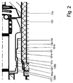
- Fig. 2 shows an enlarged section of the pump 100 according to Fig. 1 from which, in particular, the concrete configuration of the outer contour of the insertion portion 117 and the receiving portion 118 results.
- the insertion portion 117 of the armature 110 in the region of an otherwise cylindrical peripheral surface on an annular outer projection 120 which extends over the entire radial circumference of the insertion portion 117.
- This radially projecting outer projection 120 also represents the maximum outer diameter of the insertion section 117 and has a radially to outwardly facing, to the peripheral surface of the Ein Sinceabrabsterrorisms 117 concentric annular surface 120a, which is connected via a first, facing in the stroke direction and thus the first core portion 103 facing surface 120b with the remaining insertion portion 117, and the second core 103 facing away from the one Surface 120c is connected to a rear portion of the insertion portion 117, so as to give a cross-section in approximately trapezoidal profile of the outer projection 120.
- the surface 120b facing the first core part 103 and the surface 120c of the outer projection 120 facing away from the first core part 103 can also be configured differently, in particular perpendicular to the longitudinal axis 153 or the main axis of the insertion section 117, or vice versa may be configured trapezoidal, so that an approximately dovetailed cross-section of the outer projection 120 is formed.
- the projection may also have a rounded contour.
- the receiving portion 118 of the second core part 104 has an inner projection 121 offset from the position of the outer projection 120 in the direction of the first core part 103, which is directed radially in the direction of the longitudinal axis 153 of the armature 110 and has a completely closed annular course.
- the outer projection 120 and the inner projection 121 are arranged spaced apart in the longitudinal direction, wherein the inner projection 121 has a concentric with the otherwise cylindrical shape of the insertion portion 117 extending inner annular surface 121 a, the one 121a facing the first core portion 103 surface with the inner ring surface 121a is connected via a second, the first core portion 103 facing away from the surface 121 c with the receiving portion 118 and facing the first surface 120 b of the outer projection 120.
- the inner projection 121 and the outer projection 120 partially overlap in the projection, so that upon excitation of the coil 102 and the stroke of the armature 110 caused thereby, the outer projection 120 comes closer to the inner projection 121. This will the force of the armature 110 is increased by the resulting axial component in the region of the secondary air gap 152, so that in an end phase of the stroke of the armature 110, the force acting on the armature 110 is increased. Conveniently, even at the maximum stroke of the armature 110, the inner projection 120 and the outer projection 121 are still spaced from each other so that contact does not occur.
- the outer projection 121 in the stroke direction of the actuator 110 upon energization of the coil 102 may be disposed behind the inner projection 120, so that then the first core portion 103 facing surface 121 b of the first core portion 103 facing away from the surface 120c , It is also possible that a plurality of inner projections 120 and / or a plurality of outer projections 121 are provided, in which case an inner projection and / or an outer projection may also be adjacent to each of two facing surfaces of adjacent projections.
- the inner projection 120 and the outer projection 121 may be formed so that they are guided past each other, so that the insertion portion 117 of the armature 110 is inserted into the receiving portion 118 of the second core member 104 from the direction of the first core member 103.
- at least one of the inner projection and the outer projection is perforated, so that the respective other can be guided past this.
- Fig. 3 shows an alternative embodiment of the secondary air gap, wherein the same or structurally comparable parts of the electromagnetic pump have the same reference numerals as in the embodiment according to FIG Fig. 1 and 2 and therefore only the differences are highlighted.
- the insertion section 217 of the armature 210 has a circumferential surface 222 tapering in the conveying direction 112, the conical shape extending over almost the entire extent of the insertion section 217.
- the cone angle, in Fig. 3 is shown, for reasons of clarity, larger than would be the case in the practical construction.
- the receiving portion 218 has a hollow cylindrical inner peripheral surface 223, so that when the coil 102 is de-energized, the thickness of the secondary air gap 252 between the insertion portion 217 and the receiving portion 218 near the end face of the receiving portion 218 is minimal, and close to the end of the receiving portion facing away from the first core portion 103 218 is maximum.
- the third embodiment according to Fig. 4 differs from the previous embodiment only in the configuration of the insertion of the armature, so that the same reference numerals as in the previous embodiment are otherwise used for the same or structurally comparable parts.
- the armature 310 has an insertion section 317, which is provided with a step 330 which is provided circumferentially around the lateral surface of the insertion section 317, so that the secondary air gap 352 has a lower thickness in an end face of the receiving section 218 facing the first core section 103
- the step 330 may also be arranged so that the recessed portion is located near the front portion 115 of the core portion 310, and also more than a step, such as a cascade of small steps over parts of the extension of the insertion section 317 or may be provided over the entire insertion section 317, wherein expediently at least a quarter of the maximum extent of the secondary air gap 352 is formed differently from the remaining circumference of the insertion.
- the magnetic resistance of the rear portion of the insertion portion 317 differs from the front larger diameter portion of the insertion portion 317, so that a maximum magnetic force is influenced accordingly.
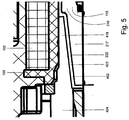
- the fourth embodiment according to Fig. 5 differs from the second embodiment according to Fig. 3 only by the differently shaped receiving portion, so that the same or structurally comparable parts as the embodiment according to Fig. 3 bear the same reference numerals.
- the in Fig. 5 Anchor 210 shown the same as the off Fig. 3
- the receiving part 418 is designed differently in that the inner peripheral surface 423 of the receiving portion 418 has a complementary to the cone shape of the insertion portion 217 cone shape, that is, is formed as an inner cone, which tapers in the conveying direction. This results in a de-energized coil 102, a secondary air gap 452 with almost constant thickness over the course of the insertion section 217, so that there is a favorable magnetic resistance by the low secondary air gap 452.
- the armature 210 Upon energization of the coil 102, the armature 210 is displaced, wherein the axial movement of the armature 210 increases the secondary air gap 452 in its thickness in proportion to the extent to which the armature 210 is displaced.
- the magnetic resistance changes over the stroke and accordingly influences the force with which the armature 210 is acted upon.
- the cone angle an exaggerated in the drawing, but noticeable axial component of the secondary air gap 452 defining parts is effective, the effect on the force is not greater than the radial component.
- Fig. 6 shows a further embodiment in which the configuration of the secondary air gap is again designed differently than in the preceding embodiments, wherein the same reference numerals as in the preceding embodiments show the same or structurally comparable parts.
- the armature 510 has an insertion section 517, which is rotationally symmetrical and whose limiting curve has a continuous, wave-like curved profile, with regions 517a of larger diameter and regions 517b of smaller diameter.
- the receiving section 518 of the second core part 504 is bounded by a rotationally symmetric envelope 523, which has regions of smaller inner diameter 523a and regions of larger inner diameter 523b. This results in a secondary air gap 552, which fluctuates over the course in its strength, wherein upon excitation of the coil 102 further changes in the strength of the secondary air gap 552 be induced, with the result of a corresponding influence on the magnetic resistance.
- curve courses 523, 517 are expediently complementary to one another, and expediently the maximum outer diameter of the insertion section 517 is smaller than the minimum inner diameter of the receiving section 518 so that the second core part 504 can be formed in one piece in particular and the armature 510 Direction of the first core part 103 can be used in the second core part 504.
- Figs. 7A to 7C 12 shows a schematic view of an electromagnetic pump 700 without representing a coil, other drive components, such as springs, or connection components to a pump space 707.
- an armature 710 is arranged, which armature 710 is axially displaceable in a conveying direction.
- the pump space 707 is limited by magnetic field guiding components 703, which for example correspond to the core parts 103, 104 and the coil carrier 105 shown in the first embodiment, but can also take other forms.
- a primary air gap is defined by a distance between the armature 710 and a conical counterpart 719.
- the armature 710 has a frustoconical contour tapering in the stroke direction in its front region 715 facing the counterpart 719.
- the conical counterpart 719 is formed on one of the magnetic field guiding components 703.
- the armature 710 in an end section facing away from the counterpart 719 and designated as an insertion section 717, has an annular outer projection 720 extending from a counter-cone 719 opposite end face of the armature 710 extends over about one sixth of the insertion portion 717 and projects radially to about a center of the secondary air gap.
- the components 703 include a receiving portion 718 in which the insertion portion 717 of the armature 710 is inserted.
- a radial inner projection 721 is arranged, which projects approximately to a center of the secondary air gap, so that the inner projection 721 and the outer projection 720 of the insertion 718 do not abut each other during a movement of the armature 710.
- Fig. 7A the outer projection 721 is arranged on a side of the inner projection 720 facing away from the pump space 707.
- a negative overlap there is no radial overlap of the outer surface of the outer projection and the inner surface of the inner projection, which is referred to herein as a negative overlap.
- the position shown of the armature 710 is a non-energized stroke position, wherein a coil, not shown, is not energized and the armature 710 is biased, for example by a spring in the stroke position shown. It is understood that a stop prevents the armature 710 against further biasing against a bias of the spring.
- Fig. 7B shows the armature 710 in a middle stroke position, wherein the inner surface of the inner projection 721 is disposed opposite to the outer surface of the outer projection 720.
- Fig. 7C shows the armature 710 in a deflected stroke position with the armature 710 fully extended out of the receiving portion 718, and with the front portion 715 of the armature 710 shown just before abutting against the counter-cone 719. Also in this position, there is a negative overlap between the inner projection 721 and the outer projection 720.
- the magnetic resistance of the entire assembly is higher than with positive coverage. Further, the magnetic resistance is further increased as the armature 710 moves out of the receiving portion 718.
- the behavior of the armature 710 is influenced to such an extent that when the armature 710 starts moving after the state in FIG Fig. 7A There is an approximately medium resistance, so that a pressure peak, which would result in a sudden energization of the coil in the pump chamber 707, is avoided. While the outer projection 720 on the inner projection 721 as in Fig. 7B moved past, the magnetic resistance decreases and the maximum force of the pump can be used for a delivery of a fluid. In the in Fig.
- Fig. 8 shows analogous to that in the Fig. 7A-C 1, a schematic view of another embodiment of an electromagnetic pump 800, without a coil, other drive components, such as springs, or connecting component to a pump chamber 807 represent.
- the same or comparable components have over the embodiments of Fig. 7 a reference number increased by 100, so that in the following a more detailed description of the position and nature of the components is dispensed with and only the differences are highlighted and described.
- the pump 800 of the embodiment according to Fig. 8 is constructed as the pump 700 of the embodiment according to Fig. 7 , wherein an insertion portion 817 of an armature 810 and a receiving portion 818, in which the armature 810 is inserted, from the insertion portion 717 and the Detect receiving section 818 of the seventh embodiment.
- the outer diameter of the insertion portion 817 and the inner diameter of the receiving portion 818 are approximately the same size, but a clearance is provided for sliding the armature 10 in the receiving portion 818.
- the insertion section 817 has, in a rear region facing away from a counter-cone 819, a groove 820a, an outer projection 820b being formed between an end face of the anchor 810 facing away from the counter-cone 819 and the groove 820a.
- the outer projection 820b has a same outer diameter as a remaining part of the insertion portion 817.
- the receiving portion 818 also has a groove 821a, wherein an outer projection 820b is formed between an end of the receiving portion 818 facing the counter-cone 819 and the groove 820a.
- the outer projection 820b has a same outer diameter as a remaining part 817a of the insertion section 817.
- FIG. 12 shows the armature 810 in a middle stroke position with the inner surface of the inner projection 821b facing the outer surface of the outer projection 820b.
- Fig. 9 shows an electromagnetic pump 900 designed as a metering pump, comprising a housing 901, an electromagnetic coil 902 arranged in the housing 901, a first ferromagnetic core part 903 and a second ferromagnetic core part 904.
- the electromagnetic coil 902 is wound on a coil support 905 and is wound in its Indoors of the first ferromagnetic core portion 903 and the second ferromagnetic core portion 904 each partially penetrated.
- the two ferromagnetic core parts 903, 904 are spaced from each other by a pumping space 907 defining a distance 906, wherein the first ferromagnetic core part 903 has a feed line 908 and the second ferromagnetic core part 904 has a discharge line 909 for a fluid to be conveyed.
- a pumping space 907 defining a distance 906
- the first ferromagnetic core part 903 has a feed line 908
- the second ferromagnetic core part 904 has a discharge line 909 for a fluid to be conveyed.
- a movable, ferromagnetic armature 910 Arranged in the pump chamber 907 is a movable, ferromagnetic armature 910, which armature 910 is biased in a conveying direction 912 of the electromagnetic pump 900 by a spring 911 arranged between the armature 910 and the first core part 903.
- the armature 910 has a substantially hollow cylindrical shape and is penetrated by a piston rod 913 in its entire longitudinal extension, wherein the piston rod 913 projects beyond the armature 110 with one end 913a in the conveying direction 912 and abuts against the drain line 909 and this with fully de-energized coil 902 closes.
- the armature 910 In its first region 915 facing the first core part 903, the armature 910 has a frustoconical contour which tapers in the stroke direction.
- the first core part 903 has a cone-shaped counterpart 919 facing the armature 910 and complementary to the front area 915 of the armature 910, wherein a region between the armature 910 and the conical armature counterpart 919 is referred to as a primary air gap.
- the front region 915 protrudes into the axial distance between both core parts 903, 904.
- the armature 910 extends with an end facing away from the first core part 903, formed as an insertion section 917 in a receiving portion 818 of the second core part 904, wherein the front portion 915 of the armature 910 does not protrude radially beyond an end face of the receiving portion 918 of the second core part 904 facing the first core part 903, whereby core parts 903, 904 with a smaller diameter can also be used.
- the front area 915 of the armature 910 it is also possible for the front area 915 of the armature 910 to protrude radially beyond the end face of the receiving portion 918 facing the first core part 903.
- An area between the insertion portion 917 of the armature 910 and the receiving portion 918 of the second core part 904 is referred to as a secondary air gap.
- the region between the front region 915 of the armature 910 and the counterpart 919 of the first core part 903 defines a primary air gap 951 whose axial extension is maximized in the case of a deenergized coil 902.
- the peripheral surface of the insertion portion 917 of the armature 910 and the receiving portion 918 of the second core portion 904 facing the longitudinal axis 953 of the spool 902 define a substantially radial, secondary air gap 952 in the region in which they oppose.
- the magnetic force between the armature 910 and the first core part 903 is greater than the magnetic force between the armature 910 and the second core part 904 due to the resulting magnetic field in a closing operation of the first air gap 951.
- a conical portion 960 of the insertion portion 917 of the armature 910 tapers against the longitudinally tapered frusto-conical contour of the front portion 915 of the armature 910, starting from an end face 961 of the insertion portion 917.
- a cylindrical region 962 of the insertion section 917 which extends up to an end wall 963 of the Insertion section 917 extends, in which the drain line 909 in a recess 964, which is greater than the end 913a of the piston rod 913, opens.
- a conical portion 970 of the insertion portion 917 of the armature 910 extends partially in radial overlap with the conical portion 960 of the insertion portion 917, partially outside the receiving portion 918, in FIG Fig. 9
- the conical portion 970 of the insertion portion 917 of the armature 910 passes completely out of radial overlap with the conical portion 960 of the insertion portion 917.
- the conical portion 970 of the insertion portion 917 closes in the direction of federation through a continuous cylindrical Region 971 of the armature 910, which is surrounded in the non-energized state partially radially from the conical portion 960 of the insertion section 917.
- a cylindrical section 972 adjoins the conical section 970 of the insertion section 917, which is adjoined in turn by the frustoconical contour of the front section 915 of the armature 910 which tapers in the stroke direction and which faces from an annular end face 973 of the first core section 903 Anchor 910 is limited.
- the conical section 970 constitutes slightly more than one sixth of the axial extent of the insertion section 917, which extends from a front side 974 of the armature 910 facing the drain line 909 to the cylindrical section 972, but without it.
- the conical section 960 constitutes slightly more than one sixth of the axial extent of the receiving section 916.
- the conical section 970 of the insertion section 917 which tapers counter to the stroke direction, is steeper than the frustoconically tapering contour of the front section 915 of the armature 910, since for approximately the same radial alignment the front section 915 has a longer axial distance Available.
- the cone angle of the conical sections 970 and 960 is approximately the same and differs by less than 8 °.
- the cone angle front portion 915 of armature 910 and counterpart 919 is approximately the same and differs by less than 8 °.
- a check valve 980 is arranged, which is biased by a spring 981 in the direction of the stroke of the armature 910 corresponding closing direction.
- a sleeve 982 is arranged, the bore 983 of the piston rod 913 is partially penetrated.
- a suction space 984 radially surrounded by the sleeve 982 between the valve member of the check valve 980 and the end face of the piston rod 913 facing the supply line 908 is connected to the pump space 907, for example via a bore containing a valve in the piston rod 913 which is not is shown further.
- the check valve 980 prevents the escape of the fluid, and this is pressed through the connection in the pump chamber 907. If the armature 910 displaced by the spring 911 back to its original position, created in the suction chamber 984, a negative pressure which lifts the valve member of the check valve 980 and allows a backflow of fluid, while the fluid upon return of the armature 910 from the pump chamber 907 in the Drain line 909 is pressed. It can be seen that the spring 911 is supported on an end face of the sleeve 982. It can also be seen that the bores in both core parts 903, 904 have a through bore which has in stages from outside to inside increasing diameter, so that a simple assembly by inserting components such as the sleeve 982 or the check valve 980 is possible.
- Fig. 9 shown and explained above features on the armature 910, in particular arrangement, length and angle of the conical portion 970 of the insertion portion 917, which also referred to as a secondary cone can be, and on the cone-shaped counterpart 919, in particular length, diameter and angle, there are additional degrees of freedom to optimize the force curve as a function of the stroke. In the present embodiment, this achieves, inter alia, a sufficient acceleration at the beginning of the stroke, a rising force with the stroke for overriding the bias of the spring 911 and a moderate and certainly not too large excess force at the end of the movement of the armature 910.
- the armature 910 securely holds the end of the stroke, but strikes the conical counterpart 919 with only a slight excess of force, even with variable supply voltage and changing coil temperature. As a result, unnecessary introduced into the Dosierpumoe 900 vibrations and temperature increases are avoided, which leads to an extension of the service life.
- the air gaps in the operation of the electromagnetic pump can not be filled with air, but with the medium to be pumped, pump oil or other medium, and in particular also the mutual leadership favoring sleeve, such as Teflon or the like may include.
- the invention has been described above with reference to an embodiment of the electromagnetic magnetic pump as an injection pump with dosing. It is understood that instead of a metering cylinder, an armature acting as a piston can be used, or that the pump can also be designed as a diaphragm pump, in which the fluid to be delivered remains outside the air gaps.
- the invention has been described above with reference to embodiments in which the insertion section and the receiving portion are formed as one-piece parts. It is understood that these parts can be composed of several parts in terms of manufacturing technology, for example, a base part with a cylindrical contour and a shrunk or pressed bushing part, which is at least partially ferromagnetic and accordingly has a specific ferromagnetic contour.
- a base part with a cylindrical contour and a shrunk or pressed bushing part which is at least partially ferromagnetic and accordingly has a specific ferromagnetic contour.
- it is possible to assemble a modular assortment by means of a corresponding socket in which the characteristic in the region of the secondary air gap is influenced by the type of the usual lining or bushing.
Landscapes
- Engineering & Computer Science (AREA)
- Mechanical Engineering (AREA)
- General Engineering & Computer Science (AREA)
- Physics & Mathematics (AREA)
- Fluid Mechanics (AREA)
- Reciprocating Pumps (AREA)
- Compressors, Vaccum Pumps And Other Relevant Systems (AREA)
- Electromagnetic Pumps, Or The Like (AREA)
Description
- Die Erfindung betrifft eine elektromagnetische Pumpe.
- Aus der Praxis bekannte elektromagnetische Pumpen weisen eine sich entlang einer Längsachse erstreckende Spule auf, wobei die Spule von einem ersten ferromagnetischen und einem zweiten ferromagnetischen Kernteil jeweils teilweise durchsetzt ist. Die ferromagnetischen Kernteile sind im Inneren der Spule voneinander beabstandet, wobei ein die beiden Kernteile zumindest teilweise durchsetzender Anker bei Erregung der Spule durch das entstehende Magnetfeld axial verlagert wird. Dabei ist zwischen dem ersten ferromagnetischen Kernteil und dem Anker ein axialer primärer Luftspalt angeordnet und zwischen dem zweiten ferromagnetischen Kernteil und dem Anker ein radialer sekundärer Luftspalt angeordnet, wobei ein in dem zweiten Kernteil geführter Einführabschnitt des Ankers zylindrisch ausgestaltet ist. Der zylindrische Einführabschnitt ist dabei in einen ebenfalls zylindrischen Aufnahmeabschnitt des zweiten Kernteils aufgenommen, wobei im Bereich der dem ersten Kernteil zugekehrten Stirnseite des Aufnahmeabschnitts eine das Einführen des Ankers erleichternde Fase vorgesehen sein kann. Nachteilig wird durch die zylindrische Ausgestaltung des Einführabschnitts die konstruktive Auslegung des Magnetkreises aber im Wesentlichen auf das erste ferromagnetische Kernteil und den dem ersten ferromagnetischen Kernteil zugewandten Ankerkopf des Ankers beschränkt. Ferner nachteilig muss die Bewegung des Ankers gegen Ende der Bestromung der Spule durch eine aufwendige Elektronik zum Abbremsen gesteuert werden, um eine Hub-Kraft-Kennlinie zu erzielen, die von einer im Wesentlichen exponentiell ansteigenden Hub-Kraft-Kennlinie abweicht.
-
DE 10 2008 058 046 A1 beschreibt in einem Ausführungsbeispiel eine elektromagnetische Hubkolbenpumpe mit einer Spule und einem ersten und einem zweiten abschnittsweise in der Spule angeordneten ferromagnetischen Kernteil. Ein ferromagnetischer Anker ist in einer Stützhülse aus einem magnetisch nicht leitenden Material verschiebbar aufgenommen, wobei die Stützhülse in einem dem ersten Kernteil zugekehrten Aufnahmeabschnitt des zweiten Kernteils vorgesehen ist. Zwischen dem Anker und dem ersten Kernteil ist ein primärer Luftspalt und zwischen einem Einführabschnitt des Ankers und einem Aufnahmeabschnitt des zweiten Kernteils ein sekundärer Luftspalt angeordnet. Der Magnetanker weist an einem dem ersten Kernteil zugekehrten Ende eine Ausnehmung auf, in der eine erste Feder aufgenommen ist, die sich an ihrem dem Anker abgekehrten Ende an dem ersten Kernteil abstützt. An einem dem zweiten Kernteil zugekehrten Ende des Ankers ist ein Abstützelement vorgesehen, an dem ein erstes Ende einer zweiten Feder abgestützt ist. Ein zweites Ende der zweiten Feder stützt sich an einer Ausnehmung eines in dem zweiten Kernteil aufgenommenen Dosierzylinders ab. Bei einer Erregung der Spule verlagert sich der Anker in Folge einer Magnetkraft entgegen einer Federkraft der ersten Feder in Richtung des ersten Kernteils, wobei der primäre Luftspalt geschlossen wird. Hierbei ist eine magnetische Kraft zwischen dem Anker und dem ersten Kernteil größer als eine magnetische Kraft zwischen dem Anker und dem zweiten Kernteil. Der Einführabschnitt und der Aufnahmeabschnitt weisen keine konischen Abschnitte auf, durch die sich eine über den Hub ändernde Hub-Kraft-Kennlinie realisieren lässt. Um von einem im Wesentlichen exponentiell ansteigenden Verlauf der Hub-Kraft-Kennlinie abzuweichen, müssen zusätzliche Maßnahmen, wie beispielsweise das Vorsehen einer Regelelektronik, getroffen werden. -
US 2009 / 0 200 499 A1 zeigt einen elektromagnetischen Linearantrieb für eine Pumpe mit einer Spule, die von einem ersten ferromagnetischen Kernteil und einem zweiten ferromagnetischen Kernteil abschnittsweise umschlossen ist. Ein ferromagnetischer Anker mit Jochabschnitten und Magnetabschnitten ist verschiebbar in einem Zentralbereich des ersten Kernteils und des zweiten Kernteils aufgenommen. Der Anker weist einen ersten Führungsabschnitt und einen zweiten Führungsabschnitt auf, mit denen der Anker in einer ersten Zentrierscheibe und einer zweiten Zentrierscheibe geführt ist. Zwischen dem Anker und dem ersten Kernteil sowie zwischen dem Anker und dem zweiten Kernteil ist ein Luftspalt ausgebildet. Zwischen dem Anker und dem ersten Kernteil ist jedoch kein primärer Luftspalt angeordnet. So ergibt sich auch keine magnetische Kraft zwischen dem Anker und dem ersten Kernteil, die bei einem Schließvorgang des ersten Luftspalts größer ist als eine magnetische Kraft zwischen dem Anker und dem zweiten Kernteil. Schließlich ist auch kein Einführabschnitt mit zumindest einem konischen Abschnitt, der einen von der kegelstumpfförmigen Kontur des vorderen Bereichs des ferromagnetischen Ankers abweichenden Öffnungswinkel aufweist, vorgesehen. -
DE 11 01 960 B beschreibt eine elektromagnetische Pumpe, umfassend eine Spule, die von einem ferromagnetischen Gehäuse umschlossen ist. Das Gehäuse bildet einen zylindrischen Pumpraum, in dem ein ferromagnetisches Kernteil aufgenommen ist. In dem Pumpraum ist außerdem ein ferromagnetischer Anker axial verschiebbar aufgenommen, wobei zwischen dem Anker und dem Kernteil ein Luftspalt gebildet ist. Der Pumpraum ist an einem dem Kernteil gegenüberliegenden Ende durch einen Verschlussflansch aus einem nicht magnetisch leitenden Material begrenzt. Der Anker ist mittels einer Feder, die sich an dem Kernteil und dem Anker abstützt, gegenüber dem Verschlussflansch vorgespannt, wobei ein Widerlager am Anker durch einen radial vorstehenden Einführabschnitt des Ankers gebildet ist, mit dem der Anker in dem Pumpraum geführt ist. Bei einer Erregung der Spule verlagert sich der Anker in Folge einer Magnetkraft entgegen einer Federkraft in Richtung des Kernteils. Nach Entregung der Spule gelangt der Anker zurück in eine vorgespannte Ausgangslage. Gemäß einem Ausführungsbeispiel kann der Anker auch eine konische Gestalt aufweisen. Ein zumindest teilweise in der Spule angeordnetes zweites Kernteil ist nicht vorgesehen, ebenso kein zumindest teilweise in der Spule angeordnetes zweites Kernteil. Ein radialer, sekundärer Luftspalt zwischen dem Einführabschnitt des Ankers und dem Aufnahmeabschnitt des zweiten Kernteils fehlt, so dass eine magnetische Kraft zwischen dem Anker und dem ersten Kernteil bei einem Schließvorgang des ersten Luftspalts größer ist als eine magnetische Kraft zwischen dem Anker und dem zweiten Kernteil. Schließlich ist auch kein Einführabschnitt mit zumindest einem konischen Abschnitt, der einen von der kegelstumpfförmigen Kontur des vorderen Bereichs des ferromagnetischen Ankers abweichenden Öffnungswinkel aufweist, gezeigt. -
DD 128 346 A1 -
DE 696 07 230 T2 beschreibt eine elektromagnetische Pumpe, umfassend eine Spule und ein erstes ferromagnetisches Kernteil. Gegenüber dem ersten Kernteil ist ein zweites ferromagnetisches Kernteil angeordnet, wobei das erste Kernteil und das zweite Kernteil eine Niederdruckkammer der Pumpe bilden. In der Niederdruckkammer ist ein ferromagnetischer Anker verschiebbar aufgenommen. Zwischen dem Anker und dem ersten Kernteil ist ein primärer Luftspalt und zwischen dem Anker und dem zweiten Kernteil ein sekundärer Luftspalt angeordnet. Der Anker weist einen Aufnahmeabschnitt auf, an dem sich ein erstes Ende einer Feder abstützt. Ein zweites Ende der Feder stützt sich an einem Fortsatz eines die Niederdruckkammer begrenzenden Gehäuseteils der Pumpe ab. Dadurch ist der Anker gegenüber einem Abstandsstück des zweiten Kernteils vorgespannt. Bei einer Erregung der Spule ist eine Magnetkraft zwischen dem Anker und dem ersten Kernteil größer als zwischen dem Anker und dem zweiten Kernteil, wodurch sich der Anker entgegen einer Federkraft in Richtung des ersten Kernteils verlagert. Hierbei verringert sich der primäre Luftspalt zwischen dem Anker und dem ersten Kernteil. In einem entregten Zustand der Spule gelangt der Anker in Folge der Federkraft zurück in eine Ausgangslage. Die Kontur des Ankers weist zylindrische Abschnitte mit unterschiedlichen Durchmessern und konische Abschnitte auf. Ein ferromagnetischer Anker mit einem dem ersten Kernteil zugewandten vorderen Bereich mit einer sich Hubrichtung verjüngenden kegelstumpfförmigen Kontur bzw. ein vorderer Bereich des Ankers, der radial über eine dem ersten Kernteil zugewandte Stirnseite des Aufnahmeabschnitts des zweiten Kernteils vorsteht, ist nicht gezeigt. Schließlich ist auch kein Einführabschnitt mit zumindest einem konischen Abschnitt vorgesehen, der einen von der kegelstumpfförmigen Kontur des vorderen Bereichs des ferromagnetischen Ankers abweichenden Öffnungswinkel aufweist. -
US 2 006 592 A zeigt eine elektromagnetische Pumpe, umfassend eine erste Spule und eine zweite Spule, die in einem Pumpengehäuse axial voneinander beabstandet angeordnet sind. Die erste Spule und die zweite Spule sind innenseitig radial durch eine Stützhülse aus einem magnetisch nicht leitenden Material begrenzt, die eine Pumpkammer der Pumpe bildet. Die Pumpkammer wird in axialer Richtung einenends durch ein erstes ferromagnetisches Kernteil begrenzt, welches teilweise von der zweiten Spule umschlossen ist. Anderenends ist die Pumpkammer in axialer Richtung durch ein zweites ferromagnetisches Kernteil begrenzt, das teilweise von der ersten Spule umschlossen ist. In der Pumpkammer ist ein ferromagnetischer Anker axial verschiebbar aufgenommen. Bei einer Erregung der ersten Spule verlagert sich der Anker in Folge einer Magnetkraft in Richtung des ersten Kernteils, wobei der primäre Luftspalt geschlossen wird. Bei Entregung der ersten Spule und Erregung der zweiten Spule kommt es aufgrund einer in entgegengesetzter Richtung wirkenden Magnetkraft zu einer Verlagerung des Ankers in Richtung des zweiten Kernteils, wobei der sekundäre Luftspalt geschlossen wird. Der Anker weist an einem ersten und einem zweiten Ende konische Einführabschnitte auf, die mit konischen Aufnahmeabschnitten in dem ersten Kernteil und dem zweiten Kernteil fluchten, so dass der Anker in das erste Kernteil und das zweite Kernteil einführbar ist. Eine elektromagnetische Pumpe mit genau einer Spule ist nicht gezeigt. Zwischen dem Einführabschnitt des Ankers und dem zu der Längsachse gewandten Aufnahmeabschnitt des zweiten Kernteils ist auch kein radialer, sekundärer Luftspalt angeordnet. Ein Einführabschnitt mit zumindest einem konischen Abschnitt, der einen von der kegelstumpfförmigen Kontur des vorderen Bereichs des ferromagnetischen Ankers abweichenden Öffnungswinkel aufweist, ist ebenso nicht gezeigt. -
FR 2 428 343 A1 - Es ist die Aufgabe der Erfindung, eine elektromagnetische Pumpe anzugeben, die eine günstige Hub-Kraft-Kennlinie ermöglicht.
- Diese Aufgabe wird erfindungsgemäß durch eine elektromagnetische Pumpe mit den Merkmalen des Anspruchs 1 gelöst.
- Erfindungsgemäß umfasst eine elektromagnetische Pumpe eine Spule, die eine Längsachse aufweist, ein zumindest teilweise in der Spule angeordnetes erstes ferromagnetisches Kernteil und ein zumindest teilweise in der Spule angeordnetes zweites ferromagnetisches Kernteil sowie einen ferromagnetischen Anker. Bei Erregung der Spule wird ein Magnetfeld erzeugt, das sich über die beiden Kernteile und den Anker erstreckt. Dabei muss das Magnetfeld einen primären Luftspalt zwischen dem Anker und dem ersten Kernteil und einen sekundären Luftspalt zwischen einem Einführabschnitt des Ankers und einem zu der Längsachse gewandten Aufnahmeabschnitt des zweiten Kernteils überbrücken, wo eine zwischen dem Anker und dem ersten Kernteil wirkende magnetische Kraft bei einem Schließvorgang stets größer als eine magnetische Kraft zwischen dem Anker und dem zweiten Kernteil ist.
- Zumindest eines von Einführabschnitt des Ankers und Aufnahmeabschnitt des zweiten Kernteils weisen eine von einer zylindrischen Gestalt abweichende Kontur auf. Die abweichende Kontur ist vorzugsweise selbst wieder zylindrisch, z.B. als radialer Ring oder radiale Nut ausgebildet. Vorteilhaft können so durch einfache geometrische Änderung des Einführabschnitts des Ankers und/oder des Aufnahmeabschnitts des zweiten Kernteils in einer Produktfamilie unterschiedliche Kennlinien entsprechend einem Bedarf realisiert werden.
- Bevorzugt weist die Hub-Kraft-Kennlinie bzw. der Hub-Kraft-Verlauf zu Beginn einer Hubbewegung eine möglichst hohe Kraft auf, wo hingegen in einem mittleren Hubbereich nur eine mittlere Kraft erzeugt wird, die zum Hubende deutlich abnimmt.
- Durch die geometrischen Änderungen ist der magnetische Widerstand am sekundären Luftspalt stark hubabhängig und wird im Vergleich zum primären Widerstand größer als bei bekannten Hubmagneten. Durch eine entsprechende Ausgestaltung der abweichenden Kontur kann eine Hubkraft des ferromagnetischen Ankers auf einen jeweiligen Bewegungsabschnitt des Ankers abgestimmt werden.
- Die elektromagnetische Pumpe ermöglicht es, durch geometrische Veränderungen der den sekundären Luftspalt begrenzenden Pumpenteile über den durch Erregen der Spule erzielten Vorschub des Ankers die Kraft zu beeinflussen, insbesondere zu erhöhen oder zu erniedrigen, und diese insbesondere über den Hubverlauf des Ankers zu verändern. So ist es insbesondere möglich, durch eine Veränderung des sekundären Luftspalts im Bereich des letzten Teils des Hubes des Ankers die Kraft so zu beeinflussen, dass der Anker nicht mit maximaler Kraft verlagert wird, sondern eine Bremsung erfährt und damit das Material der Pumpe einem geringeren Verschleiß unterliegt. Hierdurch kann eine aufwändige elektronische Abregelung der Bestromung der Spule vermieden werden und eine einfache und kostengünstige Ansteuerung vorgesehen werden. Ferner wird die Lebensdauer der elektromagnetischen Pumpe verlängert und die mechanische Beanspruchung der entsprechenden Teile der Pumpe reduziert.
- Gemäß einer ersten bevorzugten Ausgestaltung der elektromagnetischen Pumpe ist vorgesehen, dass mindestens eines von Einführabschnitt des Ankers und Aufnahmeabschnitt des zweiten Kernteils über einen Bereich von wenigstens einem Sechstel, vorzugsweise einem Viertel einer maximalen axialen Erstreckung des sekundären Luftspalts eine von der zylindrischen Gestalt abweichende Kontur aufweist.
- Zweckmäßigerweise ist der Bereich, in dem die von der zylindrischen Kontur abweichende Kontur des Einführabschnitts oder des Aufnahmeabschnitts vorgesehen ist, von der dem ersten Kernteil zugekehrten Stirnseite des zweiten Kernteils beabstandet vorgesehen. Beispielsweise kann die von der zylindrischen Kontur abweichende Kontur durch eine Stufe im Bereich des Aufnahmeabschnitts oder des Einführabschnitts gebildet sein, wobei auch mehrere Stufen vorgesehen sein können. Insbesondere ist es möglich, dass auch der von der zylindrischen Kontur des Umfangs des Einführabschnitts abweichende Bereich selbst wieder einen zylindrischen Umfangsabschnitt aufweist, deren Abstand zu der Achse des Ankers jedoch von demjenigen des Umfangs des Einführabschnitts abweicht. Es ist möglich, dass der entsprechende Bereich aus mehreren Teilstufen besteht, wobei diese vorzugsweise rotationssymetrisch ausgebildet sind. Es ist aber auch möglich, von der Rotationssymmetrie abweichende Ausgestaltungen vorzusehen. Vorzugsweise kann eine Einschnürung an einem dem ersten Kernteil zugewandten Ende des Aufnahmebereichs des zweiten Kernteils vorgesehen sein. Dadurch wird vorteilhaft der Magnetwiderstand in einem Endbereich der Hubbewegung des Ankers reduziert, so dass ein kraftvoller Fluidausstoß erzielt werden kann. Vorteilhaft kann aber auch eine Einschnürung an einem dem ersten Kernteil abgewandten Ende des Aufnahmebereichs des zweiten Kernteils vorgesehen sein. Dadurch wird vorteilhaft der Magnetwiderstand in dem Endbereich der Hubbewegung des Ankers erhöht, so dass vorteilhaft eine Bremsung der Hubbewegung vor einem Auftreffen des Ankers auf das erste Kernteil stattfindet.
- Zweckmäßigerweise sind sowohl der Einführabschnitt als auch der Aufnahmeabschnitt mit einem von der zylindrischen Kontur abweichenden Bereich ausgestattet, der sich vorzugsweise, aber nicht zwangsläufig, partiell überlagert, so dass aufgrund des Hubes des Aktors die Konfiguration des sekundären Luftspalts wenigstens über ein Sechstel, vorzugsweise ein Viertel der maximalen Erstreckung des sekundären Luftspalts, die dieser im entregten Zustand der Spule einnimmt, beeinflusst wird. So kann beispielsweise vorgesehen sein, dass ein gegenüber dem Umfang des Einführabschnitts rückspringender Bereich an dem Einführabschnitt derart vorgesehen ist, dass dieser mit einem ebenfalls rückspringenden Bereich an dem Aufnahmeabschnitt derart angeordnet ist, dass der Einführabschnitt und der Aufnahmeabschnitt bei Erreichen eines bestimmten Hubes des Aktors in Überdeckung kommen und damit diese Phase des Hubes besonders beeinflussen. Entsprechendes kann für die Anfangsphase des Hubes vorgesehen sein. Besonders bevorzugt bilden der rückspringende Bereich des Aufnahmeabschnitts eine Einschnürung an einem dem ersten Kernteil zugewandten Ende des Aufnahmeabschnitts und der rückspringende Bereich des Einführabschnitts einen Flansch an einem dem ersten Kernteil abgewandten Ende des Ankers. Dabei kommt es vorteilhaft zu einer starken Reduzierung des magnetischen Widerstands in einem Endbereich der der Hubbewegung des Ankers.
- Gemäß einer bevorzugten Weiterbildung ist vorgesehen, dass mindestens eines von Einführabschnitt des Ankers und Aufnahmeabschnitt des zweiten Kernteils über einen Bereich von wenigstens einem Drittel einer maximalen axialen Erstreckung des sekundären Luftspalts eine von der zylindrischen Kontur abweichende Kontur aufweist. Zweckmäßigerweise macht derjenige Bereich der maximalen axialen Erstreckung des sekundären Luftspalts, über den sich der Einführabschnitt und/oder der Aufnahmeabschnitt von einer zylindrischen Kontur abweichen, mehr als die Hälfte, insbesondere bevorzugt mehr als drei Viertel der entsprechenden Erstreckung aus, so dass der sich einstellende Effekt bei der Verlagerung des Ankers besonders ausgeprägt ist. Insbesondere ist vorzugsweise vorgesehen, dass sowohl der Einführabschnitt als auch der Aufnahmeabschnitt von der zylindrischen Gestalt abweichen, um dadurch eine besonders effektive Beeinflussung des sekundären Luftspalts zu erreichen. Vorzugsweise erstreckt sich die abweichende Kontur über mehrere und/oder größere Bereiche, wobei besonders bevorzugt zumindest zwei von der zylindrischen Kontur abweichende und voneinander beabstandete Konturabschnitte vorgesehen sind. Dadurch wird vorteilhaft eine elektromagnetische Pumpe geschaffen, die eine verbesserte magnetische Flußleitung zu genau definierbaren Zeitpunkten der Bewegung des Ankers aufweist.
- Gemäß einer zweiten bevorzugten Ausgestaltung der elektromagnetischen Pumpe ist vorgesehen, dass mindestens eines von Einführabschnitt des Ankers und Aufnahmeabschnitt des zweiten Kernteils über einen Bereich von mindestens einem Sechstel, vorzugsweise einem Viertel einer maximalen Erstreckung des sekundären Luftspalts konisch ausgebildet ist. Alternativ kann anstelle der konischen Ausbildung oder in Kombination mit der konischen Ausbildung eine parabelförmige, elliptische oder hyperbolische Ausbildung des Einführabschnitts des Ankers oder des Aufnahmeabschnitts des zweiten Kernteils vorgesehen sein. Durch die geeignete Wahl der Form des Einführabschnitts oder des Aüfnahmeabschnitts kann eine an eine spezifische Situation angepasste Pumpe geschaffen werden. Zweckmäßigerweise erstreckt sich der entsprechend ausgebildete Einführabschnitt beziehungsweise Aufnahmeabschnitt über mehr als die Hälfte der axialen Erstreckung der entsprechenden Teile, insbesondere über die gesamte axiale Erstreckung im Bereich des sekundären Luftspaltes. Dies lässt sich fertigungstechnisch einfach herstellen, indem der Aufnahmeabschnitt insgesamt, jedenfalls aber über den Bereich, der den Einführabschnitt des Ankers aufnimmt, eine leicht konische Ausgestaltung erfährt, die von der zylindrischen Gestalt allerdings nur um wenige Winkelgrade abweicht. Zweckmäßigerweise, aber nicht zwangsläufig, mit demselben Konuswinkel ist der Einführabschnitt des Ankers ausgebildet, so dass bei entregter Spule der Außenkonus des Einführabschnitts die größte Nähe zu dem Innenkonus des Aufnahmeabschnitts aufweist. Mit Erregung der Spule vergrößert sich die Breite des sekundären Luftspalts, und entsprechend wird die Kraft mit zunehmendem Hub des Ankers reduziert. Alternativ ist es möglich, durch umgekehrte Orientierung des Innenkonus und des Außenkonus die Kraft bei zunehmendem Hub zu vergrößern. Es versteht sich, dass die Abschnitte, die konusförmig ausgebildet sind, auch mit zylindrischen Stufen voneinander beabstandet sein können, oder aber nur in Bereichen des Umfangs des Abschnitts vorgesehen sein können.
- Gemäß einer dritten bevorzugten Ausgestaltung der elektromagnetischen Pumpe ist vorgesehen, dass genau eines von Einführabschnitt des Ankers und Aufnahmeabschnitt des zweiten Kernteils eine Stufung mit verbreitertem sekundären Luftspalt aufweist. Hierdurch ist es in effektiver Weise nur notwendig, eines der beiden Teile, Einführabschnitt des Ankers und Aufnahmeabschnitt des zweiten Kernteils, dahingehend zu bearbeiten, dass es eine Stufung mit verbreitetem sekundären Luftspalt aufweist, beispielsweise indem an dem Einführabschnitt des Ankers ein Rücksprung vorgesehen ist, der eine prismatische oder eine abgerundete Ringnut bildet, oder bei dem eine rückspringende und zweckmäßigerweise umlaufende Ringnut im Bereich des Aufnahmeabschnitts vorgesehen ist. Insbesondere wenn der Einführabschnitt des Ankers entsprechend ausgebildet wird, lässt sich dies fertigungstechnisch in einfacher Weise bewerkstelligen, und ein entsprechend bearbeiteter Anker kann in bestehende Kernteile eingesetzt werden. Ferner kann je nach Auswahl der Lage der Stufung an dem Anker eine unterschiedliche Charakteristik sowohl bezogen auf den Hub als auch auf die Intensität der Änderung der Kraft eingestellt werden, so dass mehrere verschiedene Anker in der Art eines Baukastens jeweils an die Bedürfnisse der spezifischen Pumpe angepasst in dasselbe Kernteil eingesetzt werden können. Die erreichte Lösung lässt sich fertigungstechnisch einfach realisieren und damit kostengünstig herstellen.
- Gemäß einer weiteren bevorzugten Ausgestaltung der elektromagnetischen Pumpe ist vorgesehen, dass ein radial von dem Einführabschnitt des Ankers vorstehender Vorsprung eine dem ersten Kernteil zugekehrte Fläche aufweist. Vorteilhaft wird bei der Bestromung der Spule eine veränderte axiale magnetische Kraft auf den Anker ermöglicht. Der radial vor dem Einführabschnitt des Ankers vorstehende Vorsprung ist zweckmäßigerweise rotationssymetrisch ausgebildet, so dass er in der Art eines Rings den Einführabschnitt umschließt. Hierbei sind verschiedene Querschnitte des Vorsprungs möglich, beispielsweise als Trapez, Dreieck, Rechteck, Schwalbenschwanz, Groß-U oder dergleichen. Ferner ist es möglich, dass mehr als ein Vorsprung vorgesehen ist, beispielsweise mit einem als Groß-W geformten Querschnitt oder mehrere hintereinander liegende Vorsprünge mit unterschiedlichem Querschnitt. Der mindestens eine Vorsprung weist eine Fläche auf, die dem ersten Kernteil zugekehrt ist, das heißt, die wenigstens eine Komponente aufweist, die in Hubrichtung des Ankers bei Bestromen weist. Diese Fläche liegt bei einer besonders einfachen Realisation in einer zu der Hubrichtung normalen Ebene, es ist aber auch möglich, dass diese Fläche eine Neigung in der Art eines Kegelstumpfes aufweist. Zweckmäßigerweise erstreckt sich der Vorsprung nur über einen Längenabschnitt des Einführabschnitts von weniger als einem Sechstel von dessen Erstreckung und ist an einer Stelle des Umfangabschnitts vorgesehen, die auch bei maximalem Hub noch von der dem ersten Kernteil zugekehrten Stirnseite des Aufnahmeabschnitts axial beabstandet ist.
- Gemäß einer weiteren bevorzugten Ausgestaltung der elektromagnetischen Pumpe ist vorgesehen, dass der Aufnahmeabschnitt des zweiten Kernteils einen zu der Längsachse weisenden Innenvorsprung aufweist. Hierdurch erhöht sich die magnetische Flussdichte in der Pumpe, so dass eine veränderte magnetische Kraft auf den Anker ausgeübt wird. Der Innenvorsprung weist zweckmäßigerweise eine dem ersten Kernteil zugekehrte Fläche auf, und bei symmetrischem Aufbau auch eine dem ersten Kernteil abgekehrte Fläche.
- Weist sowohl der Einführabschnitt des Ankers einen vorstehenden Vorsprung als auch der Aufnahmeabschnitt des zweiten Kernteils einen Innenvorsprung auf, lassen sich durch magnetische Wechselwirkung dieser beiden Teile, die sich über den Hub des Ankers annähern oder voneinander entfernen, Kraftkomponenten erzielen, die die Kraft des Ankers über den Hub erhöhen oder erniedrigen. Damit wird im Bereich des sekundären Luftspalts eine axiale Kraftkomponente wirksam, die sich durch die Auswahl der Lage des Vorsprungs beziehungsweise des Innenvorsprungs leicht realisieren lässt. Durch die geeignete Anordnung von Vorsprung und Innenvorsprung, das heißt, ob der Vorsprung in Richtung auf den Innenvorsprung oder von dem Innenvorsprung verlagert wird, ergeben sich die jeweils gewünschten Kraftkomponenten. Es versteht sich, dass sich überlagernde Effekte beim Vorsehen von mehr als einem Vorsprung und/oder mehr als einem Innenvorsprung möglich sind. Zweckmäßigerweise überdecken sich der Innenvorsprung und der Vorsprung in axialer Projektion teilweise. Hierbei sind vorzugsweise die wirksamen axialen Flächen der sich axial gegenüberliegenden Abschnitte der beiden Vorsprünge deutlich kleiner als die sich axial gegenüberliegenden Flächen von Ankerkonus und Ankergegenstück; vorzugsweise beträgt das Verhältnis der Flächen weniger als 1:10, besonders bevorzugt weniger als 1:25.
- Gemäß einer bevorzugten Weiterbildung der elektromagnetischen Pumpe ist im Bereich des sekundären Luftspalts der maximale Außendurchmesser des Einführabschnitts des Ankers kleiner als der minimale Innendurchmesser des Aufnahmeabschnitts des zweiten Kernteils. Dadurch wird erreicht, dass die Pumpe vorteilhaft einfach zu montieren ist, ohne dass eine zweiteilige oder mehrteilige Ausgestaltung eines des ersten oder des zweiten Kernteils notwendig ist, da der Anker einfach in das zweite Kernteil eingesetzt werden kann, ohne dass beispielsweise eine Verdrehung des zweiten Kernteils gegenüber dem Anker oder eine zweiteilige Ausgestaltung des zweiten Kernteils benötigt wird.
- Gemäß einer bevorzugten Ausgestaltung ist vorgesehen, dass die von einer zylindrischen Gestalt abweichende Kontur eine Mehrzahl von Stufen aufweist. Hierzu kann die Mehrzahl in dem Einführabschnitt des Ankers und/oder in dem Aufnahmeabschnitt des zweiten Kernteils vorgesehen sein, wodurch sich über den Hub individuell anpassbare bzw. beeinflussbare Kraftverläufe ergeben. Durch das Vorsehen von mehreren axial versetzten Konturabschnitten wird vorteilhaft auch bei kleinem Magnethub eine ausreichende Überdeckungsfläche zwischen dem Anker und dem Aufnahmeabschnitt erreicht, da diese für den magnetischen Widerstand parallel wirken.
- In einer bevorzugten Weiterbildung wird der Einführabschnitt des Ankers aus dem Aufnahmeabschnitt des zweiten Kernteils vorzugsweise vollständig heraus bewegt. Dadurch erhöht sich der magnetische Widerstand, was vorteilhaft eine Abbremsung der Bewegung des Ankers zu einem Ende der Hubbewegung erzielt, wobei dadurch vorteilhaft die Stärke des Auftreffens des Ankers an dem ersten Kernteil zum Ende der Hubbewegung gedämpft wird.
- Zur Führung des Ankers kann in Verlängerung des Aufnahmeabschnitts eine Stützhülse aus Kunststoff oder dergleichen vorgesehen sein. Ebenso kann die Stützhülse zur Auskleidung einer rückspringenden Nut in Anker oder Aufnahmeabschnitt vorgesehen sein. Insbesondere dann, wenn die rückspringende Nut im Bereich der Stirnseite des Aufnahmeabschnitts angeordnet ist, aus dem der Einführabschnitt des Ankers zumindest so weit austritt, dass nur noch die Nut den Einführabschnitt überdeckt, bewirkt die Stützhülse ohne spürbare Beeinträchtigung der Magnetkraft eine Zentrierung des Einführabschnitts. Hierzu ist die Stützhülse zweckmäßig aus einem Material ausgewählt, das nicht magnetisch leitend ist und damit magnetisch einem Luftspalt im Wesentlichen gleichzusetzen ist. Alternativ kann auch ein Material vorgesehen werden, dass eine gegenüber dem Material des Aufnahmeabschnitts schlechtere magnetische Leitfähigkeit aufweist, wodurch im Bereich der Auskleidung der magnetische Widerstand einstellbar ist, z.B. ein Kunststoff mit eingelagerten ferromagnetischen Partikeln. Insbesondere kann die Stützhülse zugleich eine von der zylindrischen Gestalt abweichenden Bereich des Aufnahmeabschnitts auskleiden und den Aufnahmeabschnitt verlängern. So kann beispielsweise eine Stützhülse aus Polytetrafluorethylen an die Stirnseite des Aufnahmeabschnitts angesetzt werden.
- Gemäß einer bevorzugten Weiterbildung ist vorgesehen, dass der vordere Bereich des Ankers radial über eine dem ersten Kernteil zugewandte Stirnseite des Aufnahmeabschnitts des zweiten Kernteils vorsteht. Es ist aber auch möglich, dass der vordere Bereich des Ankers einen reduzierten Außendurchmesser aufweist, der nicht radial über die dem ersten Kernteil zugewandte Stirnseite des Aufnahmeabschnitts vorsteht. Hierdurch ist die im Bereich des primären Luftspalts sich einstellende Magnetkraft geringer dimensionierbar und entsprechend überlagert diese die sich im Bereich des sekundären Luftspalts sich einstellende Magnetkraft zwar noch, da die axiale Komponente des Magnetfeldes die radiale Komponente des Magnetfeldes deuztlich überwiegt. Gleichwohl kann damit ein vergleichsweise sanftes Ansprechverhalten des Ankers auf die Betromung erreicht werden, vor allem dann, wenn eine entgegen gerichtete axiale Komponente des Magnetfeldes im Bereich des sekundären Luftspalts beeinflusst. Durch die Einstellung der entsprechenden Parameter lässt sich beispielsweise der ausgeführte Hub des Ankers über die die Stromstärke zumindest annähernd linearisieren, wodurch sich besonders günstig auch Teilhübe einstellen lassen, beispielsweise bei einer druckregelnden Pumpe. Bei einer druckregelnden Pumpe ist die Federkraft und ggfs. die wirksamen Kolbenflächen des Ankers so abgestimmt, dass der Anker nicht in einem Ruck entgegen der Hubrichtung zurückgestellt wird und ein bestimmtes Volumen ausgestoßen wird, sondern ein Druck in der Auslassleitung eingestellt wird.
- Vorzugsweise zeichnet sich eine elektromagnetische Pumpe dadurch aus, dass der konischen Abschnitt des Einführabschnitt des Ankers sich entgegen der sich in Hubrichtung verjüngende kegelstumpfförmige Kontur des vorderen Bereichs des Ankers verjüngt, wodurch eine axiale, insbesondere entgegen der Hubrichtung wirkenden Komponente der den Aktor verlagernden Magnetkraft erreicht wird.
- Hierbei ist vorteilhaft vorgesehen, dass der konischen Abschnitt des Einführabschnitt des Ankers sich teilweise außerhalb des Aufnahmeabschnitt erstreckt.
- Vorzugsweise grenzt dann der sich entgegen der Hubrichtung verjüngende konische Abschnitt des Aufnahmeabschnitts an eine dem ersten Kernteil zugekehrte Stirnseite des zweiten Kernteils.
- Zweckmäßigerweise ist der sich entgegen der Hubrichtung verjüngende konische Abschnitt des Einführabschnitts des Ankers steiler als die sich in Hubrichtung verjüngende kegelstumpfförmige Kontur des vorderen Bereichs des Ankers.
- Eine besonders einfach montierbare Pumpe ergibt sich, wenn der außerhalb des sich entgegen der Hubrichtung verjüngende konische Abschnitt des Aufnahmeabschnitts gelegene in Pumprichtung weisende Bereich des Aufnahmeabschnitts zylindrisch ausgebildet ist. Insbesondere wenn der in den Zylinderbereich des Aufnahmeabschnitts eindringende Bereich des Einführabschnitts ebenfalls zylindrisch ausgebildet ist, lassen sich beide Teile einfach ineinanderstecken.
- Die elektromagnetische Pumpe ist bevorzugt ausgewählt aus der Gruppe umfassend Hubkolbenpumpe, Membranpumpe, druckregelnde Pumpe und Dosierpumpe.
- Weitere Vorteile, Eigenschaften und Weiterbildung der Erfindung ergeben sich aus der nachfolgenden Beschreibung von bevorzugten Ausführungsbeispielen sowie aus den abhängigen Ansprüchen.
- Fig. 1
- zeigt einen Längsschnitt durch eine elektromagnetische Pumpe mit einer ersten bevorzugten Ausführungsform eines sekundären Luftspaltes.
- Fig. 2
- zeigt einen vergrößerten Ausschnitt der Ausführungsform gemäß
Fig. 1 . - Fig. 3
- zeigt eine zweite Ausführungsform des sekundären Luftspaltes mit einem konusförmigen Gefälle des Einführabschnitts.
- Fig. 4
- zeigt eine dritte Ausführungsform des sekundären Luftspaltes mit einer Stufung des Einführabschnitts.
- Fig. 5
- zeigt eine vierte Ausführungsform des sekundären Luftspaltes mit einem konusförmigen Gefälle des Einführungsabschnitts und komplementärem Aufnahmeabschnitt.
- Fig. 6
- zeigt eine fünfte Ausführungsform des sekundären Luftspaltes mit einer wellenförmigen Kontur des Einführabschnitts.
- Fig. 7A-C
- zeigen den Bewegungsablauf einer sechsten Ausführungsform des sekundären Luftspalts.
- Fig. 8
- zeigt eine weitere Ausführungsform des sekundären Luftspalts mit Nuten im Einführabschnitt und Aufnahmeabschnitt.
- Fig. 9
- zeigt einen Längsschnitt durch eine elektromagnetische Pumpe mit einer weiteren bevorzugten Ausführungsform eines sekundären Luftspaltes.
-
Fig. 1 zeigt eine als Dosierpumpe ausgebildete elektromagnetische Pumpe 100, mit einem Gehäuse 101, eine in dem Gehäuse 101 angeordnete elektromagnetische Spule 102, einem ersten ferromagnetischen Kernteil 103 und einem zweiten ferromagnetischen Kernteil 104. Die elektromagnetische Spule 102 ist auf einem Spulenträger 105 aufgewickelt und wird in ihrem Innenbereich von dem ersten ferromagnetischen Kernteil 103 und dem zweiten ferromagnetischen Kernteil 104 jeweils teilweise durchsetzt. Die beiden ferromagnetischen Kernteile 103, 104 sind durch einen einen Abstand 106 definierenden Pumpenraum 107 voneinander beabstandet, wobei das erste ferromagnetische Kernteil 103 eine Zulaufleitung 108 und das zweite ferromagnetische Kernteil 104 eine Ablaufleitung 109 für ein zu förderndes Fluid aufweisen. In dem Pumpenraum 107 ist ein beweglicher, ferromagnetischer Anker 110 angeordnet, welcher Anker 110 durch eine zwischen dem Anker 110 und dem ersten Kernteil 103 angeordnete Feder 111 in eine Förderrichtung 112 der elektromagnetischen Pumpe 100 vorgespannt wird. Der Anker 110 weist im Wesentlichen eine hohlzylindrische Form auf und wird von einer Kolbenstange 113 in seiner gesamten Längserstreckung durchsetzt, wobei die Kolbenstange 113 über den Anker 110 in Förderrichtung 112 hinausragt und dabei einen Dosierzylinder 114 durchsetzt. Der Anker 110 weist in seinem dem ersten Kernteil 103 zugewandten vorderen Bereich 115 eine sich in Hubrichtung verjüngende kegelstumpfförmige Kontur auf. Das erste Kernteil 103 weist ein dem Anker 110 zugewandtes und zu dem vorderen Bereich 115 des Ankers 110 komplementär ausgebildetes konusförmiges Gegenstück 119 auf, wobei ein Bereich zwischen dem Anker 110 und dem konusförmigen Ankergegenstück 119 als primärer Luftspalt bezeichnet wird. Der vordere Bereich 115 ragt in den axialen Abstand zwischen beide Kernteile 103, 104. Der Anker 110 erstreckt sich mit einem dem ersten Kernteil 103 abgewandten, als Einführabschnitt 117 ausgebildeten Ende in einen Aufnahmeabschnitt 118 des zweiten Kernteils 104, wobei der vordere Bereich 115 des Ankers 110 radial über eine dem ersten Kernteil 103 zugewandte Stirnseite des Aufnahmeabschnitt 118 des zweiten Kernteils 104 vorsteht. Ein Bereich zwischen dem Einführabschnitt 117 des Ankers 110 und dem Aufnahmeabschnitt 118 des zweiten Kernteils 104 wird als sekundärer Luftspalt bezeichnet. - Der Bereich zwischen dem vorderen Bereich 115 des Ankers 110 und dem Gegenstück 119 des ersten Kernteils 103 definiert einen primären Luftspalt 151, dessen axiale Erstreckung bei entregter Spule 102 maximal ist. Die Umfangsfläche des Einführabschnitts 117 des Ankers 110 und der der Längsachse der Spule 102 zugekehrte Aufnahmeabschnitt 118 des zweiten Kernteils 104 definieren in dem Bereich, in dem diese sich gegenüber stehen, einen im Wesentlichen radialen, sekundären Luftspalt 152. Die Längsachse ist in
Fig. 1 mit 153 bezeichnet. Bei Bestromung der Spule 102 ist aufgrund des sich ergebenden Magnetfeldes die magnetische Kraft zwischen dem Anker 110 und dem ersten Kernteil 103 bei einem Schließvorgang des ersten Luftspalts 151 größer als die magnetische Kraft zwischen dem Anker 110 und dem zweiten Kernteil 104. - Bei einer Bestromung der Spule 102 entsteht ein magnetisches Feld innerhalb der Spule 102, wobei der ferromagnetische Anker 110 entgegen der Förderrichtung 112 von einer magnetischen Kraft beaufschlagt und verlagert wird. Die magnetische Kraft bewegt den Anker 110 entgegen der Vorspannung der Feder 111 in Richtung des ersten Kernteils 103, wobei der vordere Bereich 115 des Ankers 110 in das komplementär ausgebildete Gegenstück 119 des ersten Kernteils 103 eingeschoben wird. Dabei wird die Feder 111 weiter gespannt. Bei einem Entstromen der Spule 102 wird der Anker 110 durch die Vorspannung der Feder 111 wieder in Förderrichtung 112 verschoben, und die Kolbenstange 113 drückt das in dem Dosierzylinder 114 liegende Fluid hinter ein Rückschlagventil 160.
-
Fig. 2 zeigt einen vergrößerten Ausschnitt der Pumpe 100 gemäßFig. 1 , aus der sich insbesondere die konkrete Ausgestaltung der Außenkontur des Einführabschnitts 117 und des Aufnahmeabschnitts 118 ergibt. Hierbei weist der Einführabschnitt 117 des Ankers 110 im Bereich einer ansonsten zylindrischen Umfangsfläche einen ringförmigen Außenvorsprung 120 auf, der sich über den gesamten radialen Umfang des Einführabschnitts 117 erstreckt. Dieser radial vorstehende Außenvorsprung 120 stellt zugleich den maximalen Außendurchmesser des Einführabschnitts 117 dar und weist eine radial nach außen weisende, zu der Umfangsfläche des Einführabsschnitts 117 konzentrische Ringfläche 120a auf, die über eine erste, in Hubrichtung weisende und damit dem ersten Kernteil 103 zugekehrte Fläche 120b mit dem übrigen Einführabschnitt 117 verbunden ist, und die über eine zweite, dem ersten Kernteil 103 abgekehrte Fläche 120c mit einem rückwärtigen Bereich des Einführabschnitts 117 verbunden ist, so dass sich eine im Querschnitt in etwa trapezförmiges Profil des Außenvorsprungs 120 ergibt. Es versteht sich, dass die dem ersten Kernteil 103 zugekehrte Fläche 120b und die dem ersten Kernteil 103 abgekehrte Fläche 120c des Außenvorsprungs 120 auch anders ausgestaltet sein können, insbesondere senkrecht auf der Längsachse 153 beziehungsweise der Hauptachse des Einführabschnitts 117 stehen können, oder aber auch umgekehrt trapezförmig ausgestaltet sein können, so dass ein annähernd schwalbenschwanzartiger Querschnitt des Außenvorsprungs 120 gebildet ist. Schließlich kann der Vorsprung auch eine abgerundete Kontur aufweisen. - Der Aufnahmeabschnitt 118 des zweiten Kernteils 104 weist einen gegenüber der Lage des Außenvorsprungs 120 in Richtung auf das erste Kernteil 103 versetzten Innenvorsprung 121 auf, der radial in Richtung auf die Längsachse 153 des Ankers 110 gerichtet ist und einen vollständig geschlossenen ringförmigen Verlauf hat. Der Außenvorsprung 120 und der Innenvorsprung 121 sind in Längsrichtung voneinander beabstandet angeordnet, wobei der Innenvorsprung 121 eine konzentrisch zu der im Übrigen zylindrischen Gestalt des Einführabschnitts 117 verlaufende Innenringfläche 121 a aufweist, die über eine dem ersten Kernteil 103 zugekehrte Fläche 121 b mit der Innenringfläche 121a verbunden ist, und die über eine zweite, dem ersten Kernteil 103 abgekehrte Fläche 121c mit dem Aufnahmeabschnitt 118 verbunden und die der ersten Fläche 120b des Außenvorsprungs 120 zugekehrt ist.
- In dem gezeigten Ausführungsbeispiel überdecken sich der Innenvorsprung 121 und der Außenvorsprung 120 in der Projektion partiell, so dass bei Erregung der Spule 102 und dem hierdurch veranlassten Hub des Ankers 110 der Außenvorsprung 120 dem Innenvorsprung 121 näher kommt. Hierdurch wird die Kraft des Ankers 110 durch die sich ergebende axiale Komponente im Bereich des sekundären Luftspalts 152 erhöht, so dass in einer Endphase des Hubes des Ankers 110 die den Anker 110 beaufschlagende Kraft erhöht wird. Zweckmäßigerweise sind selbst bei maximalem Hub des Ankers 110 der Innenvorsprung 120 und der Außenvorsprung 121 noch voneinander beabstandet, so dass es nicht zu einem Kontakt kommt.
- Es versteht sich, dass alternativ der Außenvorsprung 121 in Hubrichtung des Aktors 110 bei Erregung der Spule 102 auch hinter dem Innenvorsprung 120 angeordnet sein kann, so dass dann die dem ersten Kernteil 103 zugekehrte Fläche 121 b der dem ersten Kernteil 103 abgekehrten Fläche 120c zugekehrt ist. Es ist weiterhin möglich, dass mehrere Innenvorsprünge 120 und/oder mehrere Außenvorsprünge 121 vorgesehen sind, wobei dann ein Innenvorsprung und/oder ein Außenvorsprung auch jeweils zwei diesem zugekehrte Flächen von benachbarten Vorsprüngen benachbart sein kann.
- Zweckmäßigerweise können der Innenvorsprung 120 und der Außenvorsprung 121 so ausgebildet sein, dass diese aneinander vorbeiführbar sind, so dass der Einführabschnitt 117 des Ankers 110 in den Aufnahmeabschnitt 118 des zweiten Kernteils 104 aus Richtung des ersten Kernteils 103 einsetzbar ist. Gemäß einer alternativen Ausgestaltung kann vorgesehen sein, dass wenigstens einer von Innenvorsprung und Außenvorsprung durchbrochen ausgebildet ist, so dass der jeweils andere hieran vorbeigeführt werden kann.
- Das erste Ausführungsbeispiel funktioniert dabei wie folgt:
- Durch die sich gegenüber liegenden Vorsprünge 120, 121 des Einführabschnitts 117 des Ankers 110 und des Aufnahmeabschnitts118 des zweiten Kernteils 104 wird eine höhere magnetische axiale Kraft auf den Anker 110 und damit eine schnellere Hubbewegung des Ankers 110 in Richtung des ersten Kernteils 103 erzielt. Gleichzeitig wird in einem Endbereich des Hubweges aufgrund einer sich, gegenüber einer rein zylindrischen Kontur des Einführabschnitts 117 und des Aufnahmeabschnitts 118 betrachtet, erhöht einstellenden Magnetwiderstands eine geringere magnetische Kraft erzielt, so dass eine schwächere Feder 111 für die Rückbewegung des Ankers 110 ausreichend ist.
-
Fig. 3 zeigt eine alternative Ausgestaltung des sekundären Luftspalts, wobei dieselben oder strukturell vergleichbare Teile der elektromagnetischen Pumpe dieselben Bezugszeichen aufweisen wie bei dem Ausführungsbeispiel gemäßFig. 1 und2 und daher nur die Unterschiede hervorgehoben werden. - Während der Aufbau der Pumpe insgesamt derjenigen des vorhergehenden Ausführungsbeispiels entspricht, weist der Einführabschnitt 217 des Ankers 210 eine sich in Förderrichtung 112 verjüngende Mantelfläche 222 auf, wobei die Konusgestalt über nahezu die gesamte Erstreckung des Einführabschnitts 217 verläuft. Der Konuswinkel, der in
Fig. 3 gezeigt wird, ist aus Gründen der Verdeutlichung größer gewählt als dies bei dem praktischen Bau der Fall wäre. Der Aufnahmeabschnitt 218 weist eine hohlzylindrische Innenumfangsfläche 223 auf, so dass bei entregter Spule 102 die Dicke des sekundären Luftspalts 252 zwischen dem Einführabschnitt 217 und dem Aufnahmeabschnitt 218 nahe der Stirnseite des Aufnahmeabschnitts 218 minimal ist, und nahe des dem ersten Kernteil 103 abgekehrten Endes des Aufnahmeabschnitts 218 maximal ist. - Es versteht sich, dass in gleicher Weise ein ähnlicher Effekt erzielbar ist, wenn der Aufnahmeabschnitt konusförmig und der Einführabschnitt zylindrisch sind, oder aber wenn sowohl der Aufnahmeabschnitt als auch der Einführabschnitt eine individuell aufeinander abgestimmte Konusgestalt aufweisen.
- Das zweite Ausführungsbeispiel funktioniert dabei wie folgt:
- Durch die gewählte Konusform des Einführabschnitts 217 ergeben sich im hinteren Bereich des Einführabschnitts 217 andere magnetische Widerstände als bei einer reinen zylindrischen Form, so dass eine maximale magnetische Kraft auf den Aktor 210 bereits zu einem früheren Zeitpunkt als bei einem Aktor mit einem zylindrischen Einführabschnitt erreicht wird.
- Das dritte Ausführungsbeispiel gemäß
Fig. 4 unterscheidet sich von dem vorhergehenden Ausführungsbeispiel nur in der Ausgestaltung des Einführabschnitts des Ankers, so dass im Übrigen für dieselben oder strukturell vergleichbare Teile dieselben Bezugszeichen wie bei dem vorhergehenden Ausführungsbeispiel Verwendung finden. - Der Anker 310 weist einen Einführabschnitt 317 auf, der mit einer Stufung 330 ausgestattet ist, die umlaufend um die Mantelfläche des Einführabschnitts 317 vorgesehen ist, so dass der sekundäre Luftspalt 352 in einer dem ersten Kernteil 103 zugekehrten Stirnseite des Aufnahmeabschnitts 218 eine geringere Stärke aufweist als in dem hinteren, dem ersten Kernteil 103 abgekehrten Bereich des Aufnahmeabschnitts 218. Es versteht sich, dass die Stufung 330 auch so angeordnet sein kann, dass der rückspringende Teil sich nahe dem vorderen Bereich 115 des Kernteils 310 befindet, und es ferner auch noch mehr als eine Stufung, wie beispielsweise eine Kaskade von kleinen Stufungen über Teile der Erstreckung des Einführabschnitts 317 oder über den gesamten Einführabschnitt 317 vorgesehen sein können, wobei zweckmäßigerweise wenigstens ein Viertel der maximalen Erstreckung des sekundären Luftspalts 352 von dem übrigen Umfang des Einführabschnitts verschieden ausgebildet ist.
- Es versteht sich, dass sich zwischen dem Ausführungsbeispiel gemäß
Fig. 3 undFig. 4 auch Kombinationen erzielen lassen, beispielsweise konische Abschnitte, die durch Stufungen voneinander getrennt sind. - Durch die gewählte Stufung unterscheidet sich der magnetische Widerstand des hinteren Bereichs des Einführabschnitts 317 von dem vorderen, einen größeren Durchmesser aufweisenden Bereich des Einführabschnitts 317, so dass eine maximale magnetische Kraft entsprechend beeinflusst wird.
- Das vierte Ausführungsbeispiel gemäß
Fig. 5 unterscheidet sich von dem zweiten Ausführungsbeispiel gemäßFig. 3 nur durch den anders gestalteten Aufnahmeabschnitt, so dass dieselben oder strukturell vergleichbare Teile wie dem Ausführungsbeispiel gemäßFig. 3 dieselben Bezugszeichen tragen. - Grundsätzlich ist der in
Fig. 5 gezeigte Anker 210 derselbe wie der ausFig. 3 , jedoch ist das Aufnahmeteil 418 dadurch anders gestaltet, dass auch die Innenumfangsfläche 423 des Aufnahmeabschnitts 418 eine zu der Konusform des Einführabschnitts 217 komplementäre Konusform aufweist, das heißt, als Innenkonus ausgebildet ist, der sich in Förderrichtung verjüngt. Hierdurch ergibt sich bei entregter Spule 102 ein sekundärer Luftspalt 452 mit nahezu konstanter Dicke über den Verlauf des Einführabschnitts 217, so dass sich durch den geringen sekundären Luftspalt 452 ein günstiger magnetischer Widerstand ergibt. Bei Erregung der Spule 102 wird der Anker 210 verlagert, wobei durch die axiale Bewegung des Ankers 210 der sekundäre Luftspalt 452 in seiner Dicke proportional zu dem Maß zunimmt, wie der Anker 210 verlagert wird. Hierdurch ändert sich der magnetische Widerstand über den Hubweg und beeinflusst entsprechend die Kraft, mit der der Anker 210 beaufschlagt wird. Hinzu kommt, dass durch den Konuswinkel eine, in der Zeichnung übertrieben dargestellte, jedoch spürbare axiale Komponente der den sekundären Luftspalt 452 definierenden Teile wirksam wird, deren Effekt auf die Kraft ungleich größer ist als die radiale Komponente. -
Fig. 6 zeigt ein weiteres Ausführungsbeispiel, bei dem die Konfiguration des sekundären Luftspalts wiederum anders ausgebildet ist als bei den vorhergehenden Ausführungsbeispielen, wobei dieselben Bezugszeichen wie in den vorhergehenden Ausführungsbeispielen dieselben oder strukturell vergleichbaren Teile zeigen. - Der Anker 510 weist einen Einführabschnitt 517 auf, der rotationssymmetrisch ausgebildet ist und dessen Begrenzungskurve ein stetiges, wellenartig geschwungenes Profil aufweist, mit Bereichen 517a größeren Durchmessers und Bereichen 517b geringeren Durchmessers. Der Aufnahmeabschnitt 518 des zweiten Kernteils 504 ist durch eine rotationssymmetrisch verlaufende Hüllkurve 523 begrenzt, die Bereiche kleineren Innendurchmessers 523a und Bereiche größeren Innendurchmessers 523b aufweist. Hierdurch ergibt sich ein sekundärer Luftspalt 552, der über den Verlauf in seiner Stärke schwankt, wobei bei Erregung der Spule 102 noch weitere Veränderungen der Stärke des sekundären Luftspalts 552 induziert werden, mit der Folge einer entsprechenden Beeinflussung des magnetischen Widerstands.
- Es versteht sich, dass zweckmäßigerweise die Kurvenverläufe 523, 517 zueinander komplementär ausgebildet sind, und hierbei zweckmäßigerweise der maximale Außendurchmesser des Einführabschnitts 517 kleiner ist als der minimale Innendurchmesser des Aufnahmeabschnitts 518, damit das zweite Kernteil 504 insbesondere einteilig ausgebildet werden kann und der Anker 510 aus Richtung des ersten Kernteils 103 in das zweite Kernteil 504 eingesetzt werden kann.
-
Fig. 7A bis 7C zeigen eine schematische Ansicht einer elektromagnetischen Pumpe 700, ohne eine Spule, andere Antriebskomponenten, wie beispielsweise Federn, oder Anschlusskomponente an einen Pumpenraum 707 darzustellen. - In dem Pumpenraum 707 ist ein Anker 710 angeordnet, welcher Anker 710 in eine Förderrichtung axial verlagerbar ist. Der Pumpenraum 707 wird von magnetfeldführenden Komponenten 703, welche beispielsweise den in dem ersten Ausführungsbeispiel gezeigten Kernteilen 103, 104 und dem Spulenträger 105 entsprechen, aber auch andere Formen annehmen können, begrenzt. Dabei ist ein primärer Luftspalt durch einen Abstand zwischen dem Anker 710 und einem konusförmigen Gegenstück 719 definiert. Der Anker 710 weist in seinem dem Gegenstück 719 zugewandten vorderen Bereich 715 eine sich in Hubrichtung verjüngende kegelstumpfförmige Kontur auf. Das konusförmige Gegenstück 719 ist dabei an einer der magnetfeldführenden Komponenten 703 ausgebildet. Der Anker 710 weist in einem dem Gegenstück 719 abgewandten als Einführabschnitt 717 bezeichneten Endabschnitt einen ringförmigen Außenvorsprung 720 auf, der sich von einer dem Gegenkonus 719 abgewandten Stirnseite des Ankers 710 über etwa ein Sechstel des Einführabschnitts 717 erstreckt und radial bis etwa zu einer Mitte des sekundären Luftspalts ragt.
- Die Komponenten 703 umfassen einen Aufnahmeabschnitt 718, in dem der Einführabschnitts 717 des Ankers 710 eingeführt ist. An dem Aufnahmeabschnitt ist ein radialer Innenvorsprung 721 angeordnet, der etwa bis zu einer Mitte des sekundären Luftspalts ragt, so dass der Innenvorsprung 721 und der Außenvorsprung 720 des Einführabschnitts 718 bei einer Bewegung des Ankers 710 nicht gegeneinander stoßen.
- In
Fig. 7A ist der Außenvorsprung 721 an einer dem Pumpenraum 707 abgewandten Seite des Innenvorsprungs 720 angeordnet. Dabei liegt keine radiale Überdeckung der äußeren Fläche des Außenvorsprung und der inneren Fläche des Innenvorsprungs vor, was vorliegend als negative Überdeckung bezeichnet wird. Die gezeigte Position des Ankers 710 ist eine unbestromte Hubposition, wobei eine nicht gezeigte Spule nicht bestromt ist und der Anker 710 beispielsweise durch eine Feder in die gezeigte Hubposition vorgespannt wird. Es versteht sich, dass ein Anschlag den Anker 710 entgegen einer Vorspannung der Feder an einer weiteren Bewegung hindert. -
Fig. 7B zeigt den Anker 710 in einer mittleren Hubposition, wobei die innere Fläche des Innenvorsprung 721 gegenüber der äußeren Fläche des Außenvorsprungs 720 angeordnet ist. -
Fig. 7C zeigt den Anker 710 in einer ausgelenkten Hubposition, wobei der Anker 710 gänzlich aus dem Aufnahmeabschnitt 718 ausgefahren ist, und wobei der vordere Bereich 715 des Ankers 710 kurz vor einem Anschlagen an dem Gegenkonus 719 gezeigt ist. Auch in dieser Position liegt eine negative Überdeckung zwischen dem Innenvorsprung 721 und dem Außenvorsprung 720 vor. - Bei einer negativen Überdeckung ist der magnetische Widerstand der gesamten Anordnung höher als bei einer positiven Überdeckung. Ferner wird der magnetische Widerstand weiter erhöht, wenn der Anker 710 aus dem Aufnahmeabschnitt 718 herausfährt.
- Dadurch wird in dem vorliegenden siebten Ausführungsbeispiel das Verhalten des Ankers 710 insoweit beeinflusst, als dass bei einem Anfahren der Bewegung des Ankers 710 nach dem Zustand in
Fig. 7A ein etwa mittelgroßer Widerstand vorliegt, so dass eine Druckspitze, die sich bei einem plötzlichen Bestromen der Spule in dem Pumpenraum 707 ergeben würde, vermieden wird. Während sich der Außenvorsprung 720 an dem Innenvorsprung 721 wie inFig. 7B vorbei bewegt, fällt der magnetische Widerstand ab und die maximale Kraft der Pumpe kann für eine Förderung eines Fluids verwandt werden. In der inFig. 7C gezeigt Position des Ankers 710 ist der magnetische Widerstand aufgrund der negativen Überdeckung sowie der Position des Anker 710 außerhalb des Aufnahmeabschnitts 718 stark angestiegen, so dass ein harter Stoß gegen den Gegenkonus 719 durch den Anker 710 vorteilhaft abgeschwächt wird. -
Fig. 8 zeigt analog zu dem in denFig. 7A-C gezeigten Ausführungsbeispiel eine schematische Ansicht eines weiteren Ausführungsbeispiels einer elektromagnetischen Pumpe 800, ohne eine Spule, andere Antriebskomponenten, wie beispielsweise Federn, oder Anschlusskomponente an einen Pumpenraum 807 darzustellen. Gleiche oder vergleichbare Komponenten weisen gegenüber dem Ausführungsbeispielen vonFig. 7 ein um 100 inkrementiertes Bezugszeichen auf, so dass im Folgenden auf eine nähere Beschreibung der Lage und Beschaffenheit der Komponenten verzichtet wird und nur die Unterschiede herausgestellt und beschrieben werden. - Die Pumpe 800 des Ausführungsbeispiels gemäß
Fig. 8 ist aufgebaut wie die Pumpe 700 des Ausführungsbeispiels gemäßFig. 7 , wobei sich ein Einführbereich 817 eines Ankers 810 sowie ein Aufnahmeabschnitt 818, in welchen der Anker 810 eingeführt ist, von dem Einführabschnitt 717 und dem Aufnahmeabschnitt 818 des siebten Ausführungsbeispiels unterscheiden. Der Außendurchmesser des Einführabschnitts 817 und der Innendurchmesser des Aufnahmeabschnitts 818 weisen etwa die gleiche Größe auf, wobei aber ein Spiel für ein Gleiten des Ankers 10 in dem Aufnahmeabschnitt 818 vorgesehen ist. Der Einführabschnitt 817 weist in einem hinteren, einem Gegenkonus 819 abgewandten Bereich eine Nut 820a, wobei ein Außenvorsprung 820b zwischen einer dem Gegenkonus 819 abgewandten Stirnseite des Ankers 810 und der Nut 820a gebildet ist. Der Außenvorsprung 820b weist einen gleichen Außendurchmesser auf wie ein übriger Teil des Einführabschnitts 817. - Der Aufnahmeabschnitt 818 weist ebenfalls eine Nut 821a auf, wobei ein Außenvorsprung 820b zwischen einem dem Gegenkonus 819 zugewandten Ende des Aufnahmeabschnitt 818 und der Nut 820a gebildet ist. Der Außenvorsprung 820b weist einen gleichen Außendurchmesser auf wie ein übriger Teil 817a des Einführabschnitts 817.
-
Fig. 8 zeigt den Anker 810 in einer mittleren Hubposition, wobei die innere Fläche des Innenvorsprung 821 b gegenüber der äußeren Fläche des Außenvorsprungs 820b angeordnet ist. - Im Unterschied zu der Pumpe 700 des siebten Ausführungsbeispiels wird eine negative Überdeckung des Einführabschnitts 817 und des Ausführungsabschnitts 818 zu Beginn einer Bewegung des Ankers 810 nicht hergestellt, so dass es nicht zu einer Reduktion des magnetischen Widerstands kommt. Dadurch wird der Anker 810 vorteilhaft schneller beschleunigt, was vorteilhaft zu einer reduzierten Betriebszeit der Spule und damit zu einem geringeren Stromverbrauch führt.
-
Fig. 9 zeigt eine als Dosierpumpe ausgebildete elektromagnetische Pumpe 900, mit einem Gehäuse 901, eine in dem Gehäuse 901 angeordnete elektromagnetische Spule 902, einem ersten ferromagnetischen Kernteil 903 und einem zweiten ferromagnetischen Kernteil 904. Die elektromagnetische Spule 902 ist auf einem Spulenträger 905 aufgewickelt und wird in ihrem Innenbereich von dem ersten ferromagnetischen Kernteil 903 und dem zweiten ferromagnetischen Kernteil 904 jeweils teilweise durchsetzt. Die beiden ferromagnetischen Kernteile 903, 904 sind durch einen einen Abstand 906 definierenden Pumpenraum 907 voneinander beabstandet, wobei das erste ferromagnetische Kernteil 903 eine Zulaufleitung 908 und das zweite ferromagnetische Kernteil 904 eine Ablaufleitung 909 für ein zu förderndes Fluid aufweisen. In dem Pumpenraum 907 ist ein beweglicher, ferromagnetischer Anker 910 angeordnet, welcher Anker 910 durch eine zwischen dem Anker 910 und dem ersten Kernteil 903 angeordnete Feder 911 in eine Förderrichtung 912 der elektromagnetischen Pumpe 900 vorgespannt wird. Der Anker 910 weist im Wesentlichen eine hohlzylindrische Form auf und wird von einer Kolbenstange 913 in seiner gesamten Längserstreckung durchsetzt, wobei die Kolbenstange 913 über den Anker 110 mit einem Ende 913a in Förderrichtung 912 hinausragt und gegen die Ablaufleitung 909 anschlägt und diese bei vollständig entstromter Spule 902 verschließt. Der Anker 910 weist in seinem dem ersten Kernteil 903 zugewandten vorderen Bereich 915 eine sich in Hubrichtung verjüngende kegelstumpfförmige Kontur auf. Das erste Kernteil 903 weist ein dem Anker 910 zugewandtes und zu dem vorderen Bereich 915 des Ankers 910 komplementär ausgebildetes konusförmiges Gegenstück 919 auf, wobei ein Bereich zwischen dem Anker 910 und dem konusförmigen Ankergegenstück 919 als primärer Luftspalt bezeichnet wird. Der vordere Bereich 915 ragt in den axialen Abstand zwischen beide Kernteile 903, 904. Der Anker 910 erstreckt sich mit einem dem ersten Kernteil 903 abgewandten, als Einführabschnitt 917 ausgebildeten Ende in einen Aufnahmeabschnitt 818 des zweiten Kernteils 904, wobei der vordere Bereich 915 des Ankers 910 radial nicht über eine dem ersten Kernteil 903 zugewandte Stirnseite des Aufnahmeabschnitt 918 des zweiten Kernteils 904 vorsteht, wodurch auch Kernteile 903, 904 mit kleinerem Durchmesser eingesetzt werden können. Es ist aber möglich, den vorderen Bereich 915 des Ankers 910 auch über die dem ersten Kernteil 903 zugewandte Stirnseite des Aufnahmeabschnitt 918 radial überstehen zu lassen. - Ein Bereich zwischen dem Einführabschnitt 917 des Ankers 910 und dem Aufnahmeabschnitt 918 des zweiten Kernteils 904 wird als sekundärer Luftspalt bezeichnet. Der Bereich zwischen dem vorderen Bereich 915 des Ankers 910 und dem Gegenstück 919 des ersten Kernteils 903 definiert einen primären Luftspalt 951, dessen axiale Erstreckung bei entregter Spule 902 maximal ist. Die Umfangsfläche des Einführabschnitts 917 des Ankers 910 und der der Längsachse 953 der Spule 902 zugekehrte Aufnahmeabschnitt 918 des zweiten Kernteils 904 definieren in dem Bereich, in dem diese sich gegenüber stehen, einen im Wesentlichen radialen, sekundären Luftspalt 952.
- Bei Bestromung der Spule 902 ist aufgrund des sich ergebenden Magnetfeldes die magnetische Kraft zwischen dem Anker 910 und dem ersten Kernteil 903 bei einem Schließvorgang des ersten Luftspalts 951 größer als die magnetische Kraft zwischen dem Anker 910 und dem zweiten Kernteil 904.
- Bei einer Bestromung der Spule 902 entsteht ein magnetisches Feld innerhalb der Spule 902, wobei der ferromagnetische Anker 910 entgegen der Förderrichtung 912 von einer magnetischen Kraft beaufschlagt und verlagert wird. Die magnetische Kraft bewegt den Anker 910 entgegen der Vorspannung der Feder 911 in Richtung des ersten Kernteils 903, wobei der vordere Bereich 915 des Ankers 910 in das komplementär ausgebildete Gegenstück 919 des ersten Kernteils 903 eingeschoben wird. Dabei wird die Feder 911 weiter gespannt. Bei einem Entstromen der Spule 902 wird der Anker 910 durch die Vorspannung der Feder 911 wieder in Förderrichtung 912 verschoben, und das Ende 913a der Kolbenstange 913 drückt das Fluid in die Ablaufleitung 909.
- Ein konischer Abschnitt 960 des Einführabschnitts 917 des Ankers 910 verjüngt sich entgegen der sich in Hubrichtung verjüngende kegelstumpfförmige Kontur des vorderen Bereichs 915 des Ankers 910, und zwar ausgehend von einer Stirnseite 961 des Einführabschnitts 917. An den einzigen und nur in eine Richtung weisenden konischen Abschnitt 960 schließt sich ein zylindrischer Bereich 962 des Einführabschnitts 917 an, der bis zu einer Stirnwand 963 des Einführabschnitts 917 reicht, in der die Ablaufleitung 909 in einer Vertiefung 964, die größer ist als das Ende 913a der Kolbenstange 913, mündet.
- Ein konischer Abschnitt 970 des Einführabschnitt 917 des Ankers 910 erstreckt sich teilweise in radialer Überdeckung mit dem konischen Abschnitt 960 des Einführabschnitts 917, teilweise außerhalb des Aufnahmeabschnitt 918, in der in
Fig. 9 gezeigten, nicht betromten Endposition des Ankers 910. Bei maximalem Hub gelangt der konische Abschnitt 970 des Einführabschnitts 917 des Ankers 910 vollständig außerhalb radialer Überdeckung mit dem konischen Abschnitt 960 des Einführabschnitts 917. An den konischen Abschnitt 970 des Einführabschnitt 917 schließt in Föderrichtung ein durchgehend zylindrischer Bereich 971 des Ankers 910 an, der im nicht bestromten Zustand teilweise radial von dem konischer Abschnitt 960 des Einführabschnitts 917umgeben ist. - In Hubrichtung schließt sich an den konischen Abschnitt 970 des Einführabschnitts 917 ein zylindrischer Abschnitt 972 an, an den sich wiederum die sich in Hubrichtung verjüngende kegelstumpfförmige Kontur des vorderen Bereichs 915 des Ankers 910 anschließt, die von einer dem ersten Kernteil 903 zugekehrten ringförmigen Stirnseite 973 des Ankers 910 begrenzt ist. Man erkennt, dass der konische Abschnitt 970 etwas mehr als ein Sechstel der axialen Erstreckung des Einführabschnitts 917 ausmacht, der von einer der Ablaufleitung 909 zugekehrten Stirnseite 974 des Ankers 910 bis zu dem zylindrischer Abschnitt 972, allerdings ohne diesen, reicht. Man erkennt ferner, dass auch der konische Abschnitt 960 etwas mehr als ein Sechstel der axialen Erstreckung des Aufnahmeabschnitts 916 ausmacht.
- Man erkennt weiter, dass der sich entgegen der Hubrichtung verjüngende konische Abschnitt 970 des Einführabschnitts 917 steiler ist als die sich in Hubrichtung verjüngende kegelstumpfförmige Kontur des vorderen Bereichs 915 des Ankers 910, da für ungefähr denselben radialen Anstand dem vorderen Bereich 915 ein längerer axialer Abstand zur Verfügung steht. Man erkennt ferner, dass der Konuswinkel der konischen Abschnitte 970 und 960 in etwa derselbe ist und sich um weniger als 8° unterscheidet. Auch der Konuswinkel von vorderem Bereich 915 des Ankers 910 und von Gegenstück 919 ist in etwa derselbe und unterscheidet sich um weniger als 8°.
- In der Zulaufleitung 908 ist ein Rückschlagventil 980 angeordnet, das von einer Feder 981 in der der Hubrichtung des Ankers 910 entsprechenden Schließrichtung vorgespannt ist. In der gegenüber der Zulaufleitung 908 vergrößerten Bohrung 903a des ersten Kernteils ist eine Hülse 982 angeordnet, deren Bohrung 983 von der Kolbenstange 913 teilweise durchsetzt ist. Ein Saugraum 984, der zwischen dem Ventilglied des Rückschlagventil 980 und der der Zulaufleitung 908 zugekehrten Stirnseite der Kolbenstange 913 von der Hülse 982 radial umgeben ist, ist mit dem Pumpraum 907 verbunden, beispielsweise über eine ein Ventil enthaltende Bohrung in der Kolbenstange 913, die nicht weiter dargestellt ist. Wird die Spule 902 bestromt, verhindert das Rückschlagventil 980 das Entweichen des Fluids, und dieses wird über die Verbindung in dem Pumpraum 907 gepresst. Wird der Anker 910 durch die Feder 911 zurück in seiner Ausgangslage verlagert, entsteht in dem Saugraum 984 ein Unterdruck, der das Ventilglied des Rückschlagventils 980 abhebt und ein Nachströmen von Fluid zulässt, während das Fluid bei Rückstellung des Ankers 910 aus dem Pumpraum 907 in die Ablaufleitung 909 gepresst wird. Man erkennt, dass die Feder 911 sich auf einer Stirnseite der Hülse 982 abstützt. Man erkennt ferner, dass die Bohrungen in beiden Kernteilen 903, 904 eine durchgehende Bohrung aufweisen, die in Stufen von außen nach innen zunehmende Durchmesser aufweist, so dass eine einfache Montage durch Einstecken von Komponenten wie der Hülse 982 oder des Rückschlagventils 980 möglich ist.
- Man erkennt ferner, dass in dem Gehäuse 901 zwei Polscheiben 991, 992 eingebracht sind, die den magnetischen Fluss zur Spule 902 nach Art eines Jochs begünstigen.
- Die in
Fig. 9 gezeigten und vorstehend erläuterten Formmerkmale am Anker 910, insbesondere Anordnung, Länge und Winkel des konischen Abschnitts 970 des Einführabschnitts 917, der auch als sekundärer Konus bezeichnet werden kann, und an dem konusförmigen Gegenstück 919, insbesondere Länge, Durchmesser und Winkel, ergeben sich zusätzliche Freiheitsgrade zur Optimierung des Kraftverlaufs als Funktion des Hubs. In der vorliegenden Ausführung erreicht man damit unter anderem eine ausreichende Beschleunigung am Anfang des Hubs, eine mit dem Hub ansteigende Kraft zur Überwidnung der Vorspannung der Feder 911 sowie einen mäßigen und jedenfalls nicht zu großen Kraftüberschuss am Ende der Bewegung des Ankers 910. Hierdurch erreicht und hält der Anker 910 sicher das Ende des Hubs, schlägt aber nur mit geringem Kraftüberschuss an dem konusförmigen Gegenstück 919 an, und zwar auch bei variabler Versorgungsspannung und sich ändernder Spulentemperatur. Hierdurch werden unnötige in die Dosierpumoe 900 eingeleitete Schwingungen und Temperaturerhöhungen vermieden, was zu einer Verlängerung der Standzeit führt. - Es versteht sich, dass die gezeigten Ausführungsbeispiele bzw. deren Elemente zur Erlangung des erfindungsgemäßes Erfolgs auch ohne weiteres kombiniert, aggregiert, substituiert oder modifiziert werden können.
- Die Erfindung ist vorstehend unter Bezugnahme auf primäre und sekundäre Luftspalte erläutert worden. Es versteht sich, dass die Luftspalte im Betrieb der elektromagnetischen Pumpe nicht mit Luft, sondern mit dem zu fördernden Medium, Pumpenöl oder einem anderen Medium gefüllt sein können, und insbesondere auch die gegenseitige Führung begünstigende Hülse, beispielsweise aus Teflon oder dergleichen, umfassen können.
- Die Erfindung ist vorstehend anhand einer Ausgestaltung der elektromagnetischen Magnetpumpe als Einspritzpumpe mit Dosierzylinder beschrieben worden. Es versteht sich, dass statt eines Dosierzylinders auch ein als Kolben wirkender Anker Einsatz finden kann, oder dass die Pumpe auch als Membranpumpe ausgebildet sein kann, bei der das zu fördernde Fluid außerhalb der Luftspalte verbleibt.
- Die Erfindung ist vorstehend anhand von Ausführungsbeispielen erläutert worden, bei dem durch Erregen der Spule der Aktor entgegen der Förderrichtung des Fluids abgehoben wird, und unter der Vorspannung der Feder das zu fördernde Fluid ausgestoßen wird. Es versteht sich, dass die Erfindung in gleicher Weise bei einer Pumpe realisiert werden kann, bei der der Ausstoß der Flüssigkeit durch den Hub des Ankers bei Erregung der Spule erfolgt, und lediglich der Rückschub unter der Vorspannung der Feder vorgesehen ist.
- Die Erfindung ist vorstehend anhand von Ausführungsbeispielen erläutert worden, bei denen spezifische Konturen des Einführabschnitts und des Aufnahmeabschnitts beschrieben wurden. Es versteht sich, dass jegliche Anpassung an eine gewünschte Hub-Kraft-Kennlinie durch erfindungsgemäße Konfiguration im Bereich des sekundären Luftspalts erreicht werden kann.
- Die Erfindung ist vorstehend anhand von Ausführungsbeispielen beschrieben worden, bei denen der Einführabschnitt und der Aufnahmeabschnitt als einstückige Teile ausgebildet sind. Es versteht sich, dass fertigungstechnisch diese Teile aus mehreren Teilen zusammengesetzt sein können, beispielsweise aus einem Grundteil mit zylindrischer Kontur und einem aufgeschrumpften oder aufgepressten Buchsenteil, welches zumindest teilweise ferromagnetisch ist und dementsprechend eine spezifische ferromagnetische Kontur aufweist. Insbesondere ist es möglich, durch eine entsprechende Buchse ein baukastenartiges Sortiment zusammenzustellen, bei dem durch die Art der gewöhnlichen Auskleidung beziehungsweise Buchse die Charakteristik im Bereich des sekundären Luftspalts beeinflusst wird. Durch eine entsprechende Ausgestaltung der Auskleidung beziehungsweise der Buchse ist es auch möglich, die ferromagnetischen Eigenschaften nicht rotationssymmetrisch über den Umfang des Einführabschnitts beziehungsweise des Aufnahmeabschnitts zu verteilen und hierdurch weitere magnetische Effekte im Bereich des sekundären Luftspalts zu erreichen.
Claims (15)
- Elektromagnetische Pumpe, umfassendgenau eine Spule (102; 902), wobei die eine Spule (102; 902) eine Längsachse (153; 953) aufweist,ein zumindest teilweise in der einen Spule (102; 902) angeordnetes ferromagnetisches erstes Kernteil (103; 903),ein zumindest teilweise in der einen Spule (102; 902) angeordnetes ferromagnetisches zweites Kernteil (104; 204; 404; 504; 904), undeinen ferromagnetischen Anker (110; 210; 310; 510; 910), wobei zwischen dem Anker (110; 210; 310; 510; 910) und dem ersten Kernteil (103; 903) ein primärer Luftspalt (151; 951) angeordnet ist, wobei zwischen einem Einführabschnitt (117; 217; 317; 517; 917) des Ankers (110; 210; 310; 510; 910) und einem zu der Längsachse (153; 953) gewandten Aufnahmeabschnitt (118; 218; 418; 518; 918) des zweiten Kernteils (104; 204; 404; 504; 904) ein radialer, sekundärer Luftspalt (152; 252; 352; 453; 553; 953) angeordnet ist,wobei der ferromagnetische Anker (110; 210; 310; 510; 910) in einem dem ersten Kernteil (103; 903) zugewandten vorderen Bereich (115; 915) eine sich in Hubrichtung verjüngende kegelstumpfförmige Kontur aufweist,
wobei eine magnetische Kraft zwischen dem Anker (110; 210; 310; 510; 910) und dem ersten Kernteil (103; 903) bei einem Schließvorgang des ersten Luftspalts (151; 951) größer ist als eine magnetische Kraft zwischen dem Anker (110; 210; 310; 510; 910) und dem zweiten Kernteil (104; 204; 404; 504; 904),
dadurch gekennzeichnet,
dass der Einführabschnitt (117; 217; 517; 917) des Ankers (110; 210; 510; 910) zumindest einen konischen Abschnitt aufweist, der einen von der kegelstumpfförmigen Kontur des vorderen Bereichs (115; 915) des ferromagnetischen Ankers (110; 210; 310; 510; 910) abweichenden Öffnungswinkel aufweist. - Elektromagnetische Pumpe nach Anspruch 1, dadurch gekennzeichnet, dass mindestens eines von Einführabschnitt (117; 217; 317; 517; 917) des Ankers (110; 210; 310; 510) und Aufnahmeabschnitt (118; 218; 418; 518; 918) des zweiten Kernteils (104; 204; 404; 504; 904) über einen Bereich von wenigstens einem Sechstel einer maximalen axialen Erstreckung des sekundären Luftspalts (152; 252; 352; 453; 553; 953) eine von der zylindrischen Kontur abweichende Kontur aufweist.
- Elektromagnetische Pumpe nach Anspruch 1 oder 2, dadurch gekennzeichnet, dass mindestens eines von Einführabschnitt (217; 917) des Ankers (210; 910) und Aufnahmeabschnitt (418; 918) des zweiten Kernteils (404; 904) über einen Bereich von mindestens einem Sechstel einer maximalen axialen Erstreckung des sekundären Luftspalts (252; 453; 952) konisch ausgebildet ist.
- Elektromagnetische Pumpe nach einem der Ansprüche 1 bis 3, dadurch gekennzeichnet, dass der Einführabschnitt (317) des Ankers (310) eine Stufung (330) mit verbreitertem sekundären Luftspalt aufweist.
- Elektromagnetische Pumpe nach einem der Ansprüche 1 bis 4, dadurch gekennzeichnet, dass der Aufnahmeabschnitt (118) des zweiten Kernteils (104) einen zu der Längsachse (153) weisenden Innenvorsprung (121) aufweist.
- Elektromagnetische Pumpe nach einem der Ansprüche 1 bis 5, dadurch gekennzeichnet, dass im Bereich des sekundären Luftspalts (152; 252; 352; 453; 553; 952) der maximale Außendurchmesser des Einführabschnitts (117; 217; 317; 517; 917) des Ankers (110; 210; 310; 510; 910) kleiner ist als der minimale Innendurchmesser des Aufnahmeabschnitts (118; 218; 418; 518; 918) des zweiten Kernteils (104; 204; 404; 504; 904).
- Elektromagnetische Pumpe nach einem der vorhergehenden Ansprüche, dadurch gekennzeichnet, dass der vordere Bereich (115) des Ankers (110; 210; 310; 510) radial über eine dem ersten Kernteil (103) zugewandte Stirnseite des Aufnahmeabschnitts (118; 218; 418; 518) des zweiten Kernteils (104; 204; 404; 504) vorsteht.
- Elektromagnetische Pumpe nach einem der vorhergehenden Ansprüche, dadurch gekennzeichnet, dass der konische Abschnitt (970) des Einführabschnitt (117; 217; 517; 917) des Ankers (110; 210; 510; 910) sich entgegen der sich in Hubrichtung verjüngende kegelstumpfförmige Kontur des vorderen Bereichs (115; 915) des Ankers (110; 210; 310; 510; 910) verjüngt.
- Elektromagnetische Pumpe nach Anspruch 8, dadurch gekennzeichnet, dass der konische Abschnitt (970) des Einführabschnitt (117; 217; 517; 917) des Ankers (110; 210; 510; 910) sich teilweise außerhalb des Aufnahmeabschnitt (118; 218; 418; 518; 918) erstreckt.
- Elektromagnetische Pumpe nach einem der vorhergehenden Ansprüche, dadurch gekennzeichnet, dass der sich entgegen der Hubrichtung verjüngende konische Abschnitt (960) des Aufnahmeabschnitts (118; 218; 418; 518; 918) an eine dem ersten erstes Kernteil (103; 903) zugekehrte Stirnseite (961) des zweiten Kernteil (104; 204; 404; 504; 904) grenzt.
- Elektromagnetische Pumpe nach einem der vorhergehenden Ansprüche, dadurch gekennzeichnet, dass der sich entgegen der Hubrichtung verjüngende konische Abschnitt (970) des Einführabschnitt (917) steiler ist als der sich in Hubrichtung verjüngende kegelstumpfförmige Kontur des vorderen Bereichs (915) des Ankers (910).
- Elektromagnetische Pumpe nach einem der vorhergehenden Ansprüche, dadurch gekennzeichnet, dass der außerhalb des sich entgegen der Hubrichtung verjüngenden konischen Abschnitts (960) des Aufnahmeabschnitts (918) gelegene in Pumprichtung (914) weisende Bereich (962) des Aufnahmeabschnitts (918) zylindrisch ausgebildet ist, und dass der in den Zylinderbereich des Aufnahmeabschnitts (918) eindringende Bereich (971) des Einführabschnitts (917) zylindrisch ausgebildet ist.
- Elektromagnetische Pumpe nach einem der vorhergehenden Ansprüche, dadurch gekennzeichnet, dass der Anker (110; 210; 310; 510; 910) seinen maximalen Durchmesser (972) in einem von der Spule (902) umgebenen Raum außerhalb des Aufnahmeabschnitts (118; 218; 418; 518; 918) des zweiten Kernteils (104; 204; 404; 504; 904) und außerhalb des ersten Kernteils (103; 903) annimmt.
- Elektromagnetische Pumpe nach einem der vorhergehenden Ansprüche, dadurch gekennzeichnet, dass die in Pumprichtung weisende wirksame Kolbenfläche des Ankers (110; 210; 310; 510; 910) größer ist als die in Hubrichtung weisende wirksame Kolbenfläche des Ankers (110; 210; 310; 510; 910).
- Elektromagnetische Pumpe nach einem der vorhergehenden Ansprüche, dadurch gekennzeichnet, dass die Pumpe ausgewählt ist aus der Gruppe umfassend Hubkolbenpumpe, Membranpumpe, druckregelnde Pumpe und Dosierpumpe.
Applications Claiming Priority (2)
| Application Number | Priority Date | Filing Date | Title |
|---|---|---|---|
| DE201210012779 DE102012012779A1 (de) | 2012-06-25 | 2012-06-25 | Elektromagnetische Pumpe |
| PCT/EP2013/001850 WO2014000878A1 (de) | 2012-06-25 | 2013-06-24 | Elektromagnetische pumpe |
Publications (2)
| Publication Number | Publication Date |
|---|---|
| EP2880312A1 EP2880312A1 (de) | 2015-06-10 |
| EP2880312B1 true EP2880312B1 (de) | 2016-04-13 |
Family
ID=48747505
Family Applications (1)
| Application Number | Title | Priority Date | Filing Date |
|---|---|---|---|
| EP13734331.5A Not-in-force EP2880312B1 (de) | 2012-06-25 | 2013-06-24 | Elektromagnetische pumpe |
Country Status (5)
| Country | Link |
|---|---|
| US (1) | US20150104338A1 (de) |
| EP (1) | EP2880312B1 (de) |
| CN (1) | CN104411971B (de) |
| DE (1) | DE102012012779A1 (de) |
| WO (1) | WO2014000878A1 (de) |
Families Citing this family (3)
| Publication number | Priority date | Publication date | Assignee | Title |
|---|---|---|---|---|
| CN107531146B (zh) * | 2015-04-13 | 2021-11-05 | 伊顿智能动力有限公司 | 鞍形燃料箱中的电子排气 |
| RU2660744C1 (ru) * | 2016-07-08 | 2018-07-09 | Федеральное государственное бюджетное образовательное учреждение высшего образования "Казанский государственный аграрный университет" (ФГБОУ ВО Казанский ГАУ) | Поршневой насос |
| CN115863047B (zh) * | 2022-11-17 | 2024-06-28 | 广州骏发电气设备有限公司 | 一种变压器低压线圈自动整形装置及其使用方法 |
Family Cites Families (17)
| Publication number | Priority date | Publication date | Assignee | Title |
|---|---|---|---|---|
| US2006592A (en) * | 1934-11-10 | 1935-07-02 | Freeman Earle | Well pumping apparatus |
| US2222823A (en) * | 1938-03-10 | 1940-11-26 | Fluidpoise Mfg Company Inc | Pumping apparatus |
| DE1101960B (de) * | 1960-01-26 | 1961-03-09 | Otto Muehlschlegel Dipl Ing | Elektromagnetisch angetriebene Freischwingerpumpe |
| US3883839A (en) * | 1973-10-29 | 1975-05-13 | Barber Colman Co | Positioning device |
| DD128346A1 (de) * | 1976-11-18 | 1977-11-16 | Eberhard Kallenbach | Schnellwirkender elektromagnet mit magneto-mechanischer abbremsung |
| FR2428343A1 (fr) * | 1978-06-05 | 1980-01-04 | Peugeot Aciers Et Outillage | Dispositif electromoteur pour engendrer des mouvements notamment lineaires |
| US4308475A (en) * | 1978-07-18 | 1981-12-29 | Sundstrand Corporation | Solenoid pump adapted for noiseless operation |
| DE3504789A1 (de) * | 1985-02-13 | 1986-08-14 | Webasto-Werk W. Baier GmbH & Co, 8035 Gauting | Elektromagnetisch betaetigte kolbenpumpe |
| US5562428A (en) * | 1995-04-07 | 1996-10-08 | Outboard Marine Corporation | Fuel injection pump having an adjustable inlet poppet valve |
| CZ292533B6 (cs) * | 1999-11-18 | 2003-10-15 | Brano-Ateso A.S., Člen Brano Group | Elektromagnetické pístové čerpadlo |
| US7078833B2 (en) * | 2002-05-31 | 2006-07-18 | Minebea Co., Ltd. | Force motor with increased proportional stroke |
| KR100725691B1 (ko) * | 2004-11-30 | 2007-06-07 | 니혼 덴산 산쿄 가부시키가이샤 | 리니어 액추에이터를 사용한 펌프 장치 |
| DE102005015117B4 (de) * | 2005-04-01 | 2007-04-26 | Webasto Ag | Hubkolbenbrennstoffpumpe und Verfahren zum Starten und Betreiben einer Kraftfahrzeugheizung |
| NZ541408A (en) * | 2005-07-21 | 2007-02-23 | Fisher & Paykel Appliances Ltd | Taper fit mounting of stator in free piston compressor motor |
| EP1878920B1 (de) * | 2006-07-12 | 2011-06-08 | Delphi Technologies Holding S.à.r.l. | Dosierpumpe für eines Reduktionsmittels |
| DE102008058046A1 (de) * | 2008-11-18 | 2010-05-20 | Thomas Magnete Gmbh | Hubkolbenpumpe |
| DE102010013106A1 (de) * | 2010-03-26 | 2011-09-29 | Thomas Magnete Gmbh | Pumpe |
-
2012
- 2012-06-25 DE DE201210012779 patent/DE102012012779A1/de not_active Withdrawn
-
2013
- 2013-06-24 WO PCT/EP2013/001850 patent/WO2014000878A1/de not_active Ceased
- 2013-06-24 CN CN201380033898.6A patent/CN104411971B/zh not_active Expired - Fee Related
- 2013-06-24 EP EP13734331.5A patent/EP2880312B1/de not_active Not-in-force
-
2014
- 2014-12-19 US US14/576,336 patent/US20150104338A1/en not_active Abandoned
Also Published As
| Publication number | Publication date |
|---|---|
| CN104411971B (zh) | 2016-12-07 |
| WO2014000878A1 (de) | 2014-01-03 |
| CN104411971A (zh) | 2015-03-11 |
| DE102012012779A1 (de) | 2014-03-27 |
| EP2880312A1 (de) | 2015-06-10 |
| US20150104338A1 (en) | 2015-04-16 |
Similar Documents
| Publication | Publication Date | Title |
|---|---|---|
| EP2308064B1 (de) | Hubmagnetanordnung und ventilanordnung | |
| DE3541938C2 (de) | Magnet-Überströmventil | |
| EP1818951B1 (de) | Hubmagnet | |
| DE102016119214A1 (de) | Solenoidventil | |
| EP2475887A1 (de) | Schwingankerpumpe | |
| DE19522187C2 (de) | Fluidsteuerventil | |
| WO2014000878A1 (de) | Elektromagnetische pumpe | |
| DE102011105586B4 (de) | Ventil | |
| DE2657197C2 (de) | ||
| EP0651858B1 (de) | Elektromagnetisch antreibbare pumpe | |
| EP0708243B1 (de) | Pumpe zum Fördern von Flüssigkeiten | |
| DE102014220670A1 (de) | Elektromagnetisch betätigbares Proportionalventil sowie Kraftstoffhochdruckpumpe mit einem solchen Proportionalventil | |
| DE112005002789T5 (de) | Stellantrieb | |
| WO2019025063A1 (de) | Elektromagnetisch betätigbares ventil und kraftstoff-hochdruckpumpe | |
| DE102008064409A1 (de) | Vorgesteuertes Ventil und ventilgesteuerte Hydromaschine | |
| EP3586696B1 (de) | Getränkepumpe | |
| DE2410768C3 (de) | Elektromagnetische Pumpe | |
| DE102008034609B4 (de) | Elektromagnet | |
| DE2206882A1 (de) | Elektromagnetisch betätigte Kolben pumpe fur Flüssigkeiten | |
| EP3078854B1 (de) | Schwingankerpumpe | |
| DE102008047364B4 (de) | Hubmagnet mit Lagerung des Hubankerkolbens im Magnetgehäuse | |
| WO2018019483A1 (de) | Magnetkreis, elektromagnetisch betätigbares saugventil und kraftstoff-hochdruckpumpe | |
| DE202016001785U1 (de) | Ventil | |
| DE102016003367A1 (de) | Ventil | |
| EP2405168B1 (de) | Ventilkörper und zugehöriges Magnetventil |
Legal Events
| Date | Code | Title | Description |
|---|---|---|---|
| PUAI | Public reference made under article 153(3) epc to a published international application that has entered the european phase |
Free format text: ORIGINAL CODE: 0009012 |
|
| 17P | Request for examination filed |
Effective date: 20141212 |
|
| AK | Designated contracting states |
Kind code of ref document: A1 Designated state(s): AL AT BE BG CH CY CZ DE DK EE ES FI FR GB GR HR HU IE IS IT LI LT LU LV MC MK MT NL NO PL PT RO RS SE SI SK SM TR |
|
| AX | Request for extension of the european patent |
Extension state: BA ME |
|
| DAX | Request for extension of the european patent (deleted) | ||
| GRAP | Despatch of communication of intention to grant a patent |
Free format text: ORIGINAL CODE: EPIDOSNIGR1 |
|
| INTG | Intention to grant announced |
Effective date: 20151019 |
|
| GRAS | Grant fee paid |
Free format text: ORIGINAL CODE: EPIDOSNIGR3 |
|
| GRAA | (expected) grant |
Free format text: ORIGINAL CODE: 0009210 |
|
| AK | Designated contracting states |
Kind code of ref document: B1 Designated state(s): AL AT BE BG CH CY CZ DE DK EE ES FI FR GB GR HR HU IE IS IT LI LT LU LV MC MK MT NL NO PL PT RO RS SE SI SK SM TR |
|
| REG | Reference to a national code |
Ref country code: GB Ref legal event code: FG4D Free format text: NOT ENGLISH |
|
| REG | Reference to a national code |
Ref country code: AT Ref legal event code: REF Ref document number: 790462 Country of ref document: AT Kind code of ref document: T Effective date: 20160415 Ref country code: CH Ref legal event code: EP |
|
| REG | Reference to a national code |
Ref country code: IE Ref legal event code: FG4D Free format text: LANGUAGE OF EP DOCUMENT: GERMAN |
|
| REG | Reference to a national code |
Ref country code: DE Ref legal event code: R096 Ref document number: 502013002602 Country of ref document: DE |
|
| REG | Reference to a national code |
Ref country code: FR Ref legal event code: PLFP Year of fee payment: 4 |
|
| REG | Reference to a national code |
Ref country code: LT Ref legal event code: MG4D |
|
| REG | Reference to a national code |
Ref country code: NL Ref legal event code: MP Effective date: 20160413 |
|
| PG25 | Lapsed in a contracting state [announced via postgrant information from national office to epo] |
Ref country code: PL Free format text: LAPSE BECAUSE OF FAILURE TO SUBMIT A TRANSLATION OF THE DESCRIPTION OR TO PAY THE FEE WITHIN THE PRESCRIBED TIME-LIMIT Effective date: 20160413 Ref country code: NL Free format text: LAPSE BECAUSE OF FAILURE TO SUBMIT A TRANSLATION OF THE DESCRIPTION OR TO PAY THE FEE WITHIN THE PRESCRIBED TIME-LIMIT Effective date: 20160413 Ref country code: FI Free format text: LAPSE BECAUSE OF FAILURE TO SUBMIT A TRANSLATION OF THE DESCRIPTION OR TO PAY THE FEE WITHIN THE PRESCRIBED TIME-LIMIT Effective date: 20160413 Ref country code: LT Free format text: LAPSE BECAUSE OF FAILURE TO SUBMIT A TRANSLATION OF THE DESCRIPTION OR TO PAY THE FEE WITHIN THE PRESCRIBED TIME-LIMIT Effective date: 20160413 Ref country code: NO Free format text: LAPSE BECAUSE OF FAILURE TO SUBMIT A TRANSLATION OF THE DESCRIPTION OR TO PAY THE FEE WITHIN THE PRESCRIBED TIME-LIMIT Effective date: 20160713 |
|
| PG25 | Lapsed in a contracting state [announced via postgrant information from national office to epo] |
Ref country code: SE Free format text: LAPSE BECAUSE OF FAILURE TO SUBMIT A TRANSLATION OF THE DESCRIPTION OR TO PAY THE FEE WITHIN THE PRESCRIBED TIME-LIMIT Effective date: 20160413 Ref country code: ES Free format text: LAPSE BECAUSE OF FAILURE TO SUBMIT A TRANSLATION OF THE DESCRIPTION OR TO PAY THE FEE WITHIN THE PRESCRIBED TIME-LIMIT Effective date: 20160413 Ref country code: PT Free format text: LAPSE BECAUSE OF FAILURE TO SUBMIT A TRANSLATION OF THE DESCRIPTION OR TO PAY THE FEE WITHIN THE PRESCRIBED TIME-LIMIT Effective date: 20160816 Ref country code: GR Free format text: LAPSE BECAUSE OF FAILURE TO SUBMIT A TRANSLATION OF THE DESCRIPTION OR TO PAY THE FEE WITHIN THE PRESCRIBED TIME-LIMIT Effective date: 20160714 Ref country code: LV Free format text: LAPSE BECAUSE OF FAILURE TO SUBMIT A TRANSLATION OF THE DESCRIPTION OR TO PAY THE FEE WITHIN THE PRESCRIBED TIME-LIMIT Effective date: 20160413 Ref country code: HR Free format text: LAPSE BECAUSE OF FAILURE TO SUBMIT A TRANSLATION OF THE DESCRIPTION OR TO PAY THE FEE WITHIN THE PRESCRIBED TIME-LIMIT Effective date: 20160413 Ref country code: RS Free format text: LAPSE BECAUSE OF FAILURE TO SUBMIT A TRANSLATION OF THE DESCRIPTION OR TO PAY THE FEE WITHIN THE PRESCRIBED TIME-LIMIT Effective date: 20160413 |
|
| PG25 | Lapsed in a contracting state [announced via postgrant information from national office to epo] |
Ref country code: BE Free format text: LAPSE BECAUSE OF NON-PAYMENT OF DUE FEES Effective date: 20160630 |
|
| REG | Reference to a national code |
Ref country code: DE Ref legal event code: R097 Ref document number: 502013002602 Country of ref document: DE |
|
| PG25 | Lapsed in a contracting state [announced via postgrant information from national office to epo] |
Ref country code: DK Free format text: LAPSE BECAUSE OF FAILURE TO SUBMIT A TRANSLATION OF THE DESCRIPTION OR TO PAY THE FEE WITHIN THE PRESCRIBED TIME-LIMIT Effective date: 20160413 Ref country code: EE Free format text: LAPSE BECAUSE OF FAILURE TO SUBMIT A TRANSLATION OF THE DESCRIPTION OR TO PAY THE FEE WITHIN THE PRESCRIBED TIME-LIMIT Effective date: 20160413 Ref country code: SK Free format text: LAPSE BECAUSE OF FAILURE TO SUBMIT A TRANSLATION OF THE DESCRIPTION OR TO PAY THE FEE WITHIN THE PRESCRIBED TIME-LIMIT Effective date: 20160413 Ref country code: MC Free format text: LAPSE BECAUSE OF FAILURE TO SUBMIT A TRANSLATION OF THE DESCRIPTION OR TO PAY THE FEE WITHIN THE PRESCRIBED TIME-LIMIT Effective date: 20160413 Ref country code: CZ Free format text: LAPSE BECAUSE OF FAILURE TO SUBMIT A TRANSLATION OF THE DESCRIPTION OR TO PAY THE FEE WITHIN THE PRESCRIBED TIME-LIMIT Effective date: 20160413 Ref country code: RO Free format text: LAPSE BECAUSE OF FAILURE TO SUBMIT A TRANSLATION OF THE DESCRIPTION OR TO PAY THE FEE WITHIN THE PRESCRIBED TIME-LIMIT Effective date: 20160413 |
|
| REG | Reference to a national code |
Ref country code: CH Ref legal event code: PL |
|
| PLBE | No opposition filed within time limit |
Free format text: ORIGINAL CODE: 0009261 |
|
| STAA | Information on the status of an ep patent application or granted ep patent |
Free format text: STATUS: NO OPPOSITION FILED WITHIN TIME LIMIT |
|
| PG25 | Lapsed in a contracting state [announced via postgrant information from national office to epo] |
Ref country code: SM Free format text: LAPSE BECAUSE OF FAILURE TO SUBMIT A TRANSLATION OF THE DESCRIPTION OR TO PAY THE FEE WITHIN THE PRESCRIBED TIME-LIMIT Effective date: 20160413 |
|
| 26N | No opposition filed |
Effective date: 20170116 |
|
| REG | Reference to a national code |
Ref country code: IE Ref legal event code: MM4A |
|
| PG25 | Lapsed in a contracting state [announced via postgrant information from national office to epo] |
Ref country code: LI Free format text: LAPSE BECAUSE OF NON-PAYMENT OF DUE FEES Effective date: 20160630 Ref country code: CH Free format text: LAPSE BECAUSE OF NON-PAYMENT OF DUE FEES Effective date: 20160630 |
|
| PG25 | Lapsed in a contracting state [announced via postgrant information from national office to epo] |
Ref country code: IE Free format text: LAPSE BECAUSE OF NON-PAYMENT OF DUE FEES Effective date: 20160624 Ref country code: SI Free format text: LAPSE BECAUSE OF FAILURE TO SUBMIT A TRANSLATION OF THE DESCRIPTION OR TO PAY THE FEE WITHIN THE PRESCRIBED TIME-LIMIT Effective date: 20160413 |
|
| REG | Reference to a national code |
Ref country code: FR Ref legal event code: PLFP Year of fee payment: 5 |
|
| GBPC | Gb: european patent ceased through non-payment of renewal fee |
Effective date: 20170624 |
|
| PG25 | Lapsed in a contracting state [announced via postgrant information from national office to epo] |
Ref country code: GB Free format text: LAPSE BECAUSE OF NON-PAYMENT OF DUE FEES Effective date: 20170624 |
|
| PG25 | Lapsed in a contracting state [announced via postgrant information from national office to epo] |
Ref country code: HU Free format text: LAPSE BECAUSE OF FAILURE TO SUBMIT A TRANSLATION OF THE DESCRIPTION OR TO PAY THE FEE WITHIN THE PRESCRIBED TIME-LIMIT; INVALID AB INITIO Effective date: 20130624 |
|
| REG | Reference to a national code |
Ref country code: FR Ref legal event code: PLFP Year of fee payment: 6 |
|
| PG25 | Lapsed in a contracting state [announced via postgrant information from national office to epo] |
Ref country code: CY Free format text: LAPSE BECAUSE OF FAILURE TO SUBMIT A TRANSLATION OF THE DESCRIPTION OR TO PAY THE FEE WITHIN THE PRESCRIBED TIME-LIMIT Effective date: 20160413 Ref country code: LU Free format text: LAPSE BECAUSE OF NON-PAYMENT OF DUE FEES Effective date: 20160624 Ref country code: IS Free format text: LAPSE BECAUSE OF FAILURE TO SUBMIT A TRANSLATION OF THE DESCRIPTION OR TO PAY THE FEE WITHIN THE PRESCRIBED TIME-LIMIT Effective date: 20160413 Ref country code: MK Free format text: LAPSE BECAUSE OF FAILURE TO SUBMIT A TRANSLATION OF THE DESCRIPTION OR TO PAY THE FEE WITHIN THE PRESCRIBED TIME-LIMIT Effective date: 20160413 Ref country code: MT Free format text: LAPSE BECAUSE OF FAILURE TO SUBMIT A TRANSLATION OF THE DESCRIPTION OR TO PAY THE FEE WITHIN THE PRESCRIBED TIME-LIMIT Effective date: 20160413 |
|
| PG25 | Lapsed in a contracting state [announced via postgrant information from national office to epo] |
Ref country code: BG Free format text: LAPSE BECAUSE OF FAILURE TO SUBMIT A TRANSLATION OF THE DESCRIPTION OR TO PAY THE FEE WITHIN THE PRESCRIBED TIME-LIMIT Effective date: 20160413 |
|
| PG25 | Lapsed in a contracting state [announced via postgrant information from national office to epo] |
Ref country code: TR Free format text: LAPSE BECAUSE OF FAILURE TO SUBMIT A TRANSLATION OF THE DESCRIPTION OR TO PAY THE FEE WITHIN THE PRESCRIBED TIME-LIMIT Effective date: 20160413 Ref country code: AL Free format text: LAPSE BECAUSE OF FAILURE TO SUBMIT A TRANSLATION OF THE DESCRIPTION OR TO PAY THE FEE WITHIN THE PRESCRIBED TIME-LIMIT Effective date: 20160413 |
|
| REG | Reference to a national code |
Ref country code: AT Ref legal event code: MM01 Ref document number: 790462 Country of ref document: AT Kind code of ref document: T Effective date: 20180624 |
|
| PG25 | Lapsed in a contracting state [announced via postgrant information from national office to epo] |
Ref country code: AT Free format text: LAPSE BECAUSE OF NON-PAYMENT OF DUE FEES Effective date: 20180624 |
|
| PGFP | Annual fee paid to national office [announced via postgrant information from national office to epo] |
Ref country code: FR Payment date: 20200619 Year of fee payment: 8 |
|
| PGFP | Annual fee paid to national office [announced via postgrant information from national office to epo] |
Ref country code: DE Payment date: 20200630 Year of fee payment: 8 |
|
| PGFP | Annual fee paid to national office [announced via postgrant information from national office to epo] |
Ref country code: IT Payment date: 20200625 Year of fee payment: 8 |
|
| REG | Reference to a national code |
Ref country code: DE Ref legal event code: R119 Ref document number: 502013002602 Country of ref document: DE |
|
| PG25 | Lapsed in a contracting state [announced via postgrant information from national office to epo] |
Ref country code: DE Free format text: LAPSE BECAUSE OF NON-PAYMENT OF DUE FEES Effective date: 20220101 |
|
| PG25 | Lapsed in a contracting state [announced via postgrant information from national office to epo] |
Ref country code: FR Free format text: LAPSE BECAUSE OF NON-PAYMENT OF DUE FEES Effective date: 20210630 |
|
| PG25 | Lapsed in a contracting state [announced via postgrant information from national office to epo] |
Ref country code: IT Free format text: LAPSE BECAUSE OF NON-PAYMENT OF DUE FEES Effective date: 20210624 |