EP2880231B1 - Schloss mit einem fallenriegel mit hilfsfalle, halteglied und schieber - Google Patents
Schloss mit einem fallenriegel mit hilfsfalle, halteglied und schieber Download PDFInfo
- Publication number
- EP2880231B1 EP2880231B1 EP13758763.0A EP13758763A EP2880231B1 EP 2880231 B1 EP2880231 B1 EP 2880231B1 EP 13758763 A EP13758763 A EP 13758763A EP 2880231 B1 EP2880231 B1 EP 2880231B1
- Authority
- EP
- European Patent Office
- Prior art keywords
- latch bolt
- latch
- lock
- holding member
- extended
- Prior art date
- Legal status (The legal status is an assumption and is not a legal conclusion. Google has not performed a legal analysis and makes no representation as to the accuracy of the status listed.)
- Active
Links
Images





Classifications
-
- E—FIXED CONSTRUCTIONS
- E05—LOCKS; KEYS; WINDOW OR DOOR FITTINGS; SAFES
- E05B—LOCKS; ACCESSORIES THEREFOR; HANDCUFFS
- E05B63/00—Locks or fastenings with special structural characteristics
- E05B63/18—Locks or fastenings with special structural characteristics with arrangements independent of the locking mechanism for retaining the bolt or latch in the retracted position
- E05B63/20—Locks or fastenings with special structural characteristics with arrangements independent of the locking mechanism for retaining the bolt or latch in the retracted position released automatically when the wing is closed
- E05B63/202—Locks or fastenings with special structural characteristics with arrangements independent of the locking mechanism for retaining the bolt or latch in the retracted position released automatically when the wing is closed a latch bolt being initially retained in an intermediate position and subsequently projected to its full extent when the wing is closed
Definitions
- the present invention relates to a lock for a door or a window, in particular a panic lock for use in escape and rescue routes. It is a self-locking lock.
- the starting point is a state of the art of a lock with the features of the preamble of patent claim 1.
- Such a lock is for example from the EP 1 840 303 A2 known.
- the lock has a latch latch and an auxiliary latch.
- the latch bolt can take three different positions. In the first retracted position, the latch bolt is fully retracted into the lock case. In the second extended position of the latch bolt is partially extended from the lock case. This second position is taken by the latch bolt with the door open. In the third extended position, the latch bolt is extended far out of the lock case. This position is taken by the latch bolt when the door is locked.
- the auxiliary latch serves to control the self-locking operation. at This lock is a bar lock from the second extended position to the third extended position only possible after both the latch bolt and the auxiliary latch were retracted into the lock case.
- the lock mechanism is complex; it comprises a first lever pivotally mounted in the lock case and a second and third lever pivotally mounted on the first lever.
- This solution is a lock for a door or a window, in particular panic lock for use in escape and rescue routes.
- the lock has a lock case with a movably mounted in the lock case latch bolt.
- the latch bolt is movable between a retracted first position, in which the latch bolt is fully retracted into the lock case, an extended second position in which the latch bolt is partially extended out of the lock case, and an extended third position, in the latch bolt far out of the lock case is extended.
- a first spring is also mounted, which urges the latch bolt in the extended third position.
- an auxiliary trap stored in the lock case.
- the auxiliary trap is between a retracted Position in which the auxiliary latch is fully retracted into the lock case, and an extended position in which the auxiliary latch is extended from the lock case, movable.
- a second spring is mounted, which urges the auxiliary latch in the extended position.
- a movably mounted in the lock case slide is provided, which is mechanically coupled to the latch bolt.
- the lock has a movably mounted in the lock case retaining member which cooperates directly or indirectly with the auxiliary latch and is movable between a blocking position in which the holding member protrudes into the path of movement of the slider and so movement of the latch bolt from the extended second Preventing position in the extended third position, and a non-blocking position, in which the holding member is outside the movement path of the slider and so allows movement of the latch bolt from the extended second position to the extended third position.
- the latch bolt and the auxiliary latch are coupled so movable that when moving the latch bolt from its extended second position to its retracted first position, the auxiliary latch is transferred directly or indirectly into its retracted position by the latch bolt.
- a holding member is provided in the lock mechanism, which cooperates with the slider mechanically coupled to the latch bolt.
- This embodiment with the holding member allows a structurally particularly simple construction of the castle while retaining the functionalities of the generic locks.
- the holding member which cooperates with the slider mechanically coupled to the latch, ensures that the latch bolt does not extend with its door open in its far extended third position.
- the holding member can in different ways with the latch bolt and with the auxiliary trap be arranged cooperatively, for example, stored between latch bolt and auxiliary latch, so that therefore the support member cooperates directly or indirectly with both the auxiliary latch and with the latch bolt.
- the holding member and the auxiliary trap can also be arranged so that the holding member acts on the auxiliary latch and the auxiliary latch interacts directly with the latch bolt.
- the holding member cooperates in this case only directly with the auxiliary latch and not with the latch bolt.
- the inventively provided holding member which cooperates with the slide, which is mechanically coupled to the latch bolt, thus creating a variety of possible arrangements of the components of the lock mechanism and thus allows particularly compact designs, which have the same high reliability against incorrect operation of the latch bolt in the open position of the door as the known complex constructed generic locks of the prior art.
- holding member is understood to mean a component which is preferably designed as a one-piece, in particular one-piece component; but the term should also be understood to mean those components which are each composed of several components.
- the holding member is mounted linearly movable.
- auxiliary latch and the holding member are coupled in such a way that when the auxiliary latch is moved into its extended position, the holding member is transferred into its position blocking the slide.
- the auxiliary latch has a driver area for the holding member and the holding member has a corresponding counter area.
- the latch bolt and the retaining member are coupled so movable, that upon movement of the latch bolt in its retracted first position, the holding member is transferred directly or indirectly into its non-blocking position.
- the latch bolt has a driver area for the holding member and the holding member has a corresponding counter area.
- a third spring is provided, which urges the holding member in its non-blocking position.
- the third spring is supported with its one end on the lock case and with its other end on the holding member.
- the spring stiffness of the second spring is greater than the spring stiffness of the third spring.
- the latch bolt has a catch area for the auxiliary latch and the auxiliary latch has a corresponding counter area.
- the holding member between the latch bolt and the auxiliary latch is interposed and cooperates directly with both the latch bolt and with the auxiliary latch.
- the slider is mounted linearly movable.
- the slider and the latch bolt are coupled in such a manner that, when the latch bolt moves from its extended second position to its extended third position, the slider is moved in the lock case.
- the slider and the latch bolt are mechanically coupled via a slot slot and a sliding pin.
- the guide pin is arranged on the latch bolt tail and engages the guide pin in the associated slot slot of the slider.
- the link slot has a first, substantially horizontally aligned portion and a second, obliquely oriented portion.
- the lock has a lock case with a lock box top, a lock case bottom and a lock face.
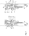
- the castle has the following essential cooperating components: a latch bolt 2 with latch bolt tail, an auxiliary latch 3 with Hilf fallenschwanz, a holding member 4, arranged between latch bolt tail and Hilfs fallenschwanz, and a slider 5.
- the slider 5 has a cam slot 5k, in which a arranged on the latch bolt tail Guide pin 2k engages.
- the holding member 4 cooperates with the latch bolt tail and the slider 5. At its other end, the holding member 4 cooperates with the auxiliary tail.
- the lock further includes a nut 6 with a handle connected thereto for manual operation by a user. Next, the lock on a lock cylinder with which the lock can be unlocked by means of a key.
- the latch bolt 2 is mounted linearly movable in the lock case.
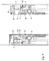
- the latch bolt 2 can assume three positions, a retracted first position (FIG. Fig. 6 ), an extended second position ( Fig. 1 ) and an extended third position ( Fig. 5 ).
- a retracted first position of the latch bolt 2 In its retracted first position of the latch bolt 2 is retracted in the lock case.
- the latch bolt 2 In the extended second position ( Fig. 1 ) and also in the extended third position ( Fig. 5 ), the latch bolt 2 is extended from the lock case, so that the latch bolt 2 protrudes from an associated opening in the lock plate.
- the latch bolt 2 in the extended second position ( Fig. 5 ) is extended by 12 mm from the lock case and that the latch bolt 2 in the further extended third position ( Fig.
- the latch bolt 2 is by a spring 2f, which in the following Fallen latch spring is called, acted upon in the extended third position.
- a first end of the latch bolt spring 2f here is supported lock box fixed; a second end of the latch bolt spring 2f is hereby supported on the latch bolt 2 itself.
- the latch bolt tail has the guide pin 2k, which serves to cooperate with the slider 5. This guide pin 2k is aligned in the usual manner of installation of the castle in the horizontal plane, perpendicular to the direction of movement of the latch bolt 2.
- the latch bolt tail further has a region 2m, which serves for the interaction of the latch bolt 2 with the retaining member 4. This area is referred to below as driver area 2m.
- the auxiliary latch 3 is linearly movable and mounted substantially parallel to the direction of movement of the latch bolt 2 in the lock case. In its retracted position, the auxiliary latch 3 is retracted into the lock case. In its extended position, the auxiliary latch 3 projects out of the lock case via an opening in the lock plate associated with the auxiliary latch 3.
- the auxiliary latch 3 is acted upon in the extended position by a spring 3f, which is referred to below as the auxiliary latch spring.
- a first end of the auxiliary latch spring 3f here is supported lock box fixed; a second end of the auxiliary latch spring 3f is in this case supported on the auxiliary latch 3 itself.
- the auxiliary tail is provided with a shoulder which can be brought into engagement with the retaining member 4 to be described.
- the slider 5 is mechanically coupled to the latch bolt 2.
- the slide 5 is linearly movably mounted in the lock case and movable in the usual manner of installation of the castle in the vertical direction.
- the slotted slot 2k has two slot portions, a first substantially horizontally oriented transverse slot portion and an inclined slit portion inclined at approximately 45 ° to the horizontal, which is vertically upwardly oriented.
- the substantially horizontally oriented slot portion of the cam slot 5k is formed in Stulpfernen area of the slider 5; the slot portion of the cam slot 5k, which is inclined upwards to the horizontal, is formed in the near-end region of the slider 5.
- the substantially horizontally oriented portion of the cam slot 5k is assigned to the extension of the latch bolt between 12 and 0 mm. In this area, the slider 5 remains in its upper position.
- the oblique section of the cam slot 5k is assigned to the extension area of the latch bolt between 12 and 20 mm. In this area, the slider 5 moves from its upper position in FIG. 2 in its lower position in FIG. 6 , In the retracted first position of the latch bolt 2 is the guide pin 2k of the latch bolt tail at Stulpfernen end of the horizontal slot portion of the slot slot 5k.
- the guide pin 2k first passes through the transverse slot portion and then penetrates into the oblique slot portion of the cam slot 5k. While the guide pin 2k passes through the oblique slot portion, the moving latch bolt 2 forces the slider 5 to move vertically downwards. In the extended third position of the latch bolt 2, the guide pin 2k of the latch bolt tail is located at the near-end of the inclined slot portion of the slot slot 5k. Furthermore, the slider 5 has a contact edge 5k for interaction with the retaining member 4 to be described later.
- the support member 4 is mounted linearly movable in the lock case.
- the holding member 4 can in this case occupy a blocking position, in which the holding member 4 projects into the path of movement of the slider 5.
- the abutment edge of the slide 5 bears against the holding member 4, wherein the holding member 4 prevents the movement of the slider 5 down.
- the holding member 4 holds the latch bolt 2 in the extended second position (FIG. Fig. 1 ); the further extension of the latch bolt 2 in its extended third position ( Fig. 5 ) is prevented by the system of the slider 5 on the holding member 4. This corresponds to the position in which the door leaf is open and does not rest against the door frame.
- an arm 4a is provided, which projects into the path of movement of the latch bolt 2, wherein the driving portion 2m of the latch bolt 2 in abutment with the arm of the support member 4 can be brought.
- the driver portion 2m of the latch bolt 2 comes into abutment against the arm 4a of the support member 4, so that the support member 4 taken from the latch bolt 2 and is moved parallel to the latch bolt 2.
- a driver portion 4m is also provided, to which the shoulder 3a of the auxiliary latch 3 can be brought into abutment.
- the auxiliary latch 3 is also moved parallel to the latch bolt 2, characterized in that the region 4m of the support member 4 rests against the shoulder 3a of the auxiliary latch 3. This means that when inserting the latch bolt 2 in the lock case, the auxiliary latch 3 is also drawn into the lock case, wherein the movement of the latch bolt 2 is transmitted via the support member 4 to the auxiliary latch 3.
- auxiliary latch 3 moves under the action of the auxiliary latch spring 3f in the extended position.
- the shoulder of the auxiliary latch 3 comes again in contact with the holding member 4, which is still in the blocking position.
- the latch bolt 2 and the auxiliary latch 3 are moved in the direction of their extended position under the action of the latch bolt spring 2f and the auxiliary latch spring 3f.
- the holding member 4 characterized in that the shoulder of the extending auxiliary latch 3 rests on the support member 4, again transferred to its blocking position.
- the latch bolt spring 2f and the auxiliary latch spring 3f are in this case matched to one another such that the auxiliary latch spring 3f transfers the holding member into its blocking position before the latch bolt 2, driven by the latch bolt spring 2f, has reached its extended second position. This means that when the latch bolt 2 has reached its extended second position, the support member 4 is already in its blocking position. The latch bolt 2 can then extend only to its extended second position. An inclusion of the latch bolt 2 in its extended third position is not possible because the support member 4 of the extending auxiliary latch 3 in the blocking position has been transferred, thereby preventing a downward movement of the slider 5 and thus an exception the latch bolt 2 in its extended third position.
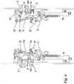
- FIGS. 7 to 10 a second embodiment of the castle is shown.
- This second embodiment comprises the same components as the embodiment of FIGS. 1 to 6 ; however, the latch bolt 2, the auxiliary latch 3 and the support member 4 cooperate in a different manner in the second embodiment.
- a third spring 4f hereinafter referred to as holding member spring 4f, is provided, which acts on the holding member 4 in the direction of its non-blocking position.
- the latch bolt tail has a region 2m, which serves for the interaction of the latch bolt 2 with the auxiliary latch 3.
- the auxiliary trap 3 has a corresponding counter area 3m.
- the areas 2m and 3m are in the FIGS. 7 . 8th . 9 and 10 each recognizable in the left part of the figure.
- the latch bolt 2 acts in this case with the auxiliary latch 3 such that when moving the latch bolt 2 from its extended second position in the direction of its retracted first position, the auxiliary latch 3 is moved in the direction of its retracted position.
- FIG. 8 in the left part of the figure, the area 2m of the latch bolt 2 is shown in abutment with the area 3m of the auxiliary latch.
- the latch bolt 2 interacts directly with the auxiliary latch 3.
- the auxiliary latch 3 has a surface on the auxiliary latch tail which serves to cooperate with the support member 4.
- the auxiliary latch 3 in this case cooperates with the holding member 4 such that upon movement of the auxiliary latch 3 in the direction of its extended position, the holding member 4 is transferred to its blocking position. In this movement, the surface of the auxiliary latch 3 is in contact with the holding member 4. Driven by the auxiliary latch spring 3f is thus the holding member 4, against the action of the holding member spring 4f, transferred by the auxiliary latch 3 in its blocking position.
- the auxiliary latch spring 4f thus urges the auxiliary latch 4f in its extended position and the holding member 4 against the action of the holding member spring 4f in the blocking position.
- the spring rate of the auxiliary latch spring 3f is to be selected larger than the spring stiffness of the holding member spring 4f.
- the latch bolt 2 When the door is open, the latch bolt 2 is in its extended second position. Here, the latch bolt 2 is acted upon by the latch bolt spring 2f in the extension direction. Since the latch bolt 2 is coupled to the slider via the guide pin 2k and the slide guide 5k, the force of the latch bolt spring 2f is transmitted to the slider 5.
- the slider 5 rests with its edge 5z on the holding member 4.
- the holding member 4 in this case prevents a downward movement of the slider 5 and holds the latch bolt 2 in its extended second position.
- the slider 5 is located at the door open with its contact edge 5z on the support member 4, so that the force of the latch bolt spring 2f acts on the support member 4. When open Doors act on the support member 4, both the force of the retaining member spring 4f and the force of the latch bolt 2f.
- the directions of these two forces are substantially perpendicular to each other.
- the spring hardnesses of the latch bolt spring 2f and the retaining member spring 4f are selected such that the force of the retaining member spring 4f is insufficient to overcome the static friction forces occurring between the retaining member 4 and contact edge 5z. This means that when the slide 5z bears on the holding member 4, the holding member 4 is held in its blocking position against the action of the holding member spring 4f.
- the self-locking mechanism of the lock according to the second embodiment will be described below.
- the driver portion 2m of the latch bolt 2 comes into contact with the area 3m of the auxiliary latch 3.
- This system of the latch bolt 2 on the auxiliary latch 2 is in Fig. 8 recognizable in the left partial figure. Due to the fact that the driver region 2m of the latch bolt 2 rests in the area 3m of the auxiliary latch 3, the auxiliary latch 3 is taken along in the lock box during the further retraction movement of the latch bolt 2 and parallel to the latch bolt 2 emotional. This ensures that the auxiliary latch 3 does not hit the strike plate. The auxiliary trap 3 is thereby spared.
- the guide pin 2k When inserting the latch bolt 2, the guide pin 2k also moves along the stülpfernen, substantially horizontal region of the cam slot 5k of the slider 5. Although this section of the cam slot 5k is referred to as “substantially horizontal”, the Kuliseenschlitz 5k in this area a slight slope, so that the slider 5 is raised when inserting the latch bolt 2 by a height in the millimeter range. The contact edge 5z of the slider 5 is then no longer on the support member 4, when the latch bolt 2 is moved from its extended second position in the direction of its retracted first position.
- the retraction of the latch bolt 2 in the lock case can be done not only by striking the latch bolt to the strike plate, but also manually by pressing a handle by a user, as in Fig. 9 is shown. Also in this case causes the retraction of the latch bolt 2 retracting the auxiliary latch 3 and the support member is, as the auxiliary latch is no longer applied to the support member, driven by the support member spring 4f transferred to the non-blocking position.
- Fig. 9 shows the lock according to the second embodiment with the latch bolt 2 in its retracted first position and the auxiliary latch 3 in its fully retracted position.
- the holding member is in its non-blocking position the slider 5.
- This stage in which the latch bolt 3 and the auxiliary latch 3 are completely retracted into the lock case, is obtained in practice only by operating the handle and corresponding maximum rotation of the nut 6.
- the latch bolt 2 and the auxiliary latch 3 are not fully inserted into the lock case; In this case, both the latch bolt and the auxiliary latch protrude out of the lock case according to the rebate clearance.
- the latch bolt 2 is no longer held by the strike plate in its retracted first position.
- the latch bolt 2 moves under the action of the latch bolt spring 2f in the latch bolt 2 associated opening on the door frame or on the active leaf into it.
- the auxiliary latch 3 is still held by the striker in its retracted position and is not in contact with the support member 4.
- the support member 4 is held by the support member spring 4f in its non-blocking position.
- the latch bolt 2 now moves, driven by the latch bolt spring 2f, in the direction of its extended position.
- the slider 5 Since the latch bolt 2 is coupled via the guide pin 2k with the guide slot 5k of the slider 5, the slider 5, as soon as the guide pin 2k has reached the oblique branch of the guide slot 5k, forcibly moved in the downward direction. Since the holding member 5 is in its non-blocking position, the slider 5 can move freely down and thus also the latch bolt 2 in its extended third position. The movement of the latch bolt 2 and the slider 5 ends when the guide pin 2k of the latch bolt 2 has reached the close to the end of the guide slot 5k. This situation is in Fig. 10 shown.
- the castle according to the second in the FIGS. 7 to 10 illustrated embodiment is safe against triggering of the self-locking mechanism by solely pressing the latch bolt 2 or the auxiliary latch 3, as will be described below.
- the auxiliary latch 3 is taken from the latch bolt 2 and retracted parallel to the latch bolt 2 in the lock case.
- the holding member 4 is in this case, driven by the holding member spring 4f, transferred to its non-blocking position.
- the latch bolt 2f driven by the latch bolt spring 2f
- the auxiliary latch spring 3f urges the auxiliary latch 3 in the direction of its extended position.
- the auxiliary latch 3 then comes back into contact with the support member 4, wherein the auxiliary latch 3 when moving in its extended position, the retaining member is transferred to its blocking position.
- the latch bolt spring 2f, the auxiliary latch spring 3f and the retaining member spring 4f are in this case matched to one another such that the retaining member 4 has already reached its blocking position before the latch bolt 2 reaches its extended second position.
- auxiliary latch 3 In a sole insertion of the auxiliary latch 3 in the lock case of the self-locking mechanism is also not triggered. In a sole insertion of the auxiliary latch 3, the auxiliary latch 3 comes out of contact with the support member 4.
- the latch bolt 2 is located with the door open in his second extended position.
- the holding member 4 remains in its blocking position, since the slider 5 rests with its contact edge 5z on the holding member 4.
- the holding member 4 is held in this by blocking friction forces acting between the support member 4 and the abutment edge 5z of the slider 5, in its blocking position.
- the force of the retainer spring 4f urging the retainer 4 into its non-blocking position is insufficient to overcome these static frictional forces.
- the holding member spring 4f is unable to urge the holding member 4 into its non-blocking position, as long as the slider 5 rests against the holding member 4 via its contact edge 5z. That is, the latch bolt 2 remains in its second extended position, even if the auxiliary latch is inserted with the door open in the lock case.
- the two embodiments of the FIGS. 1 to 6 and 7 to 10 differ in that in the first embodiment, the holding member 4 is interposed between the latch bolt 2 and the Hifsfalle 3 and the auxiliary latch 3 when retracting the latch bolt 2 is only indirectly taken from the latch bolt.
- the auxiliary latch 3 interacts directly with the latch bolt 2, so that the auxiliary latch 3 is taken along by the latch bolt 2 when retracting the latch bolt 2.
- the holding member 4 is acted upon by a spring 4f while the retaining member 4 in a non-blocking position, ie the slider 5 non-blocking position urges.
- no retaining member spring 4f is present, that is, the retaining member 4 is not acted upon by a spring. Instead, the holding member between the latch bolt 2 and the auxiliary latch 3 is connected.
Landscapes
- Engineering & Computer Science (AREA)
- Structural Engineering (AREA)
- Lock And Its Accessories (AREA)
Applications Claiming Priority (2)
| Application Number | Priority Date | Filing Date | Title |
|---|---|---|---|
| DE102012015345 | 2012-08-06 | ||
| PCT/EP2013/066513 WO2014023750A1 (de) | 2012-08-06 | 2013-08-06 | Schloss mit einem fallenriegel mit hilfsfalle, halteglied und schieber |
Publications (2)
| Publication Number | Publication Date |
|---|---|
| EP2880231A1 EP2880231A1 (de) | 2015-06-10 |
| EP2880231B1 true EP2880231B1 (de) | 2018-11-07 |
Family
ID=48953385
Family Applications (2)
| Application Number | Title | Priority Date | Filing Date |
|---|---|---|---|
| EP13758763.0A Active EP2880231B1 (de) | 2012-08-06 | 2013-08-06 | Schloss mit einem fallenriegel mit hilfsfalle, halteglied und schieber |
| EP13747832.7A Active EP2880233B1 (de) | 2012-08-06 | 2013-08-06 | Schlosseinrichtung für eine tür, fenster oder dergleichen mit einem fallenriegel mit auslöseglied und blockiereinrichtung |
Family Applications After (1)
| Application Number | Title | Priority Date | Filing Date |
|---|---|---|---|
| EP13747832.7A Active EP2880233B1 (de) | 2012-08-06 | 2013-08-06 | Schlosseinrichtung für eine tür, fenster oder dergleichen mit einem fallenriegel mit auslöseglied und blockiereinrichtung |
Country Status (4)
| Country | Link |
|---|---|
| EP (2) | EP2880231B1 (pl) |
| ES (1) | ES2698956T3 (pl) |
| PL (1) | PL2880233T3 (pl) |
| WO (2) | WO2014023749A2 (pl) |
Families Citing this family (1)
| Publication number | Priority date | Publication date | Assignee | Title |
|---|---|---|---|---|
| CN114046108B (zh) * | 2021-11-19 | 2025-01-10 | 上海向安实业有限公司 | 逃生门锁 |
Family Cites Families (13)
| Publication number | Priority date | Publication date | Assignee | Title |
|---|---|---|---|---|
| US5469723A (en) * | 1990-07-25 | 1995-11-28 | Litwin; Noel | Safety locks |
| US5474342A (en) * | 1993-08-04 | 1995-12-12 | Smith; Jerry R. | Door latch actuator |
| EP0866905A4 (en) * | 1995-12-12 | 1999-01-20 | Jerry R Smith | OPERATING DEVICE FOR A DOOR |
| DE19652601C1 (de) | 1996-12-18 | 1998-06-25 | Dorma Gmbh & Co Kg | Ent- und Verriegelung für eine einen Standflügel und einen Gangflügel aufweisende Tür |
| DE10063784B4 (de) * | 2000-12-21 | 2007-11-15 | Wilka Schließtechnik GmbH | Schloss |
| FI115066B (fi) | 2001-01-26 | 2005-02-28 | Abloy Oy | Järjestely vinoteljen ulostulopituuden ohjaamiseksi ovenlukossa |
| DE102004013646A1 (de) * | 2004-03-12 | 2005-09-29 | Wilka Schließtechnik GmbH | Panikschloss |
| DE102006030552A1 (de) * | 2005-07-14 | 2007-01-18 | Kfv Karl Fliether Gmbh & Co. Kg | Fluchttürschloss |
| FI20065200A7 (fi) * | 2006-03-28 | 2007-09-29 | Bjoerkboda Laas Oy Ab | Ovenlukon aputelkijärjestely |
| WO2009147689A1 (en) * | 2008-06-05 | 2009-12-10 | Cisa S.P.A. | Universal security lock |
| CN102137979A (zh) * | 2008-08-05 | 2011-07-27 | 西莎股份公司 | 推拉门的通用锁 |
| DE102009003860B4 (de) * | 2009-04-30 | 2015-10-22 | Wilka Schließtechnik GmbH | Panikschloss mit durch Betätigung eines der Riegelstirn zugeordneten Auslösers aushebbarer Zuhaltung |
| DE202011001842U1 (de) | 2011-01-14 | 2011-04-21 | Bks Gmbh | Verriegelungseinrichtung |
-
2013
- 2013-08-06 WO PCT/EP2013/066512 patent/WO2014023749A2/de not_active Ceased
- 2013-08-06 WO PCT/EP2013/066513 patent/WO2014023750A1/de not_active Ceased
- 2013-08-06 PL PL13747832T patent/PL2880233T3/pl unknown
- 2013-08-06 ES ES13747832T patent/ES2698956T3/es active Active
- 2013-08-06 EP EP13758763.0A patent/EP2880231B1/de active Active
- 2013-08-06 EP EP13747832.7A patent/EP2880233B1/de active Active
Non-Patent Citations (1)
| Title |
|---|
| None * |
Also Published As
| Publication number | Publication date |
|---|---|
| EP2880231A1 (de) | 2015-06-10 |
| EP2880233B1 (de) | 2018-09-19 |
| PL2880233T3 (pl) | 2019-02-28 |
| WO2014023749A3 (de) | 2014-06-26 |
| WO2014023749A2 (de) | 2014-02-13 |
| WO2014023750A1 (de) | 2014-02-13 |
| EP2880233A2 (de) | 2015-06-10 |
| ES2698956T3 (es) | 2019-02-06 |
Similar Documents
| Publication | Publication Date | Title |
|---|---|---|
| DE19701761C1 (de) | Selbstverriegelndes Schloß | |
| EP2703585B1 (de) | Schlosseinrichtung für einen Passivflügel mit Riegelstangeneinrichtung mit Manipulationsschutzeinrichtung | |
| EP1932989A2 (de) | Schliessanlage für Türen, Fenster oder dergleichen, insbesondere Treibstangenschloss mit Panikfunktion und Mehrpunktverriegelung | |
| EP2860332B1 (de) | Drückerbetätigbares, selbstverriegelndes Schloss | |
| EP3372757A1 (de) | Verriegelungseinheit für eine schliessanlage einer tür | |
| EP1526236B1 (de) | Vorrichtung zum Verriegeln und zum Betätigen von Klappen, Türen oder dgl. | |
| EP0521262A1 (de) | Schloss | |
| EP2757216B1 (de) | Schlosseinrichtung mit Riegelstangen-Betätigungshandhabe | |
| DE3520268A1 (de) | Ausgangseinrichtung | |
| EP2706174B1 (de) | Schloss für eine tür | |
| EP3569800B1 (de) | Schloss, insbesondere sperrfallenschloss | |
| DE2546549C3 (de) | Doppeltwirkendes Paniktürschloß mit Falle und Riegel | |
| DE3940393C2 (de) | Sicherheitsschloß | |
| DE102004013646A1 (de) | Panikschloss | |
| DE3931101C2 (pl) | ||
| EP3628801B1 (de) | Schlossvorrichtung für eine tür und verfahren zum öffnen einer tür | |
| DE2738746B2 (de) | Auslösevorrichtung für ein Paniktürschloß mit Falle und Riegel | |
| EP3112564A1 (de) | Selbstverriegelndes fallenschloss | |
| EP3907357A1 (de) | Verriegelungsvorrichtung | |
| EP2880231A1 (de) | Schloss mit einem fallenriegel mit hilfsfalle, halteglied und schieber | |
| EP2085543B1 (de) | Schloss | |
| EP3216952B1 (de) | Verriegelungseinrichtung | |
| DE3825823C2 (pl) | ||
| DE102013013547A1 (de) | Schloss mit Riegel mit Entriegelungspin | |
| DE102016207937B4 (de) | Schloss mit mehreren Verriegelungselementen |
Legal Events
| Date | Code | Title | Description |
|---|---|---|---|
| PUAI | Public reference made under article 153(3) epc to a published international application that has entered the european phase |
Free format text: ORIGINAL CODE: 0009012 |
|
| 17P | Request for examination filed |
Effective date: 20150210 |
|
| AK | Designated contracting states |
Kind code of ref document: A1 Designated state(s): AL AT BE BG CH CY CZ DE DK EE ES FI FR GB GR HR HU IE IS IT LI LT LU LV MC MK MT NL NO PL PT RO RS SE SI SK SM TR |
|
| AX | Request for extension of the european patent |
Extension state: BA ME |
|
| DAX | Request for extension of the european patent (deleted) | ||
| GRAP | Despatch of communication of intention to grant a patent |
Free format text: ORIGINAL CODE: EPIDOSNIGR1 |
|
| STAA | Information on the status of an ep patent application or granted ep patent |
Free format text: STATUS: GRANT OF PATENT IS INTENDED |
|
| INTG | Intention to grant announced |
Effective date: 20180209 |
|
| GRAJ | Information related to disapproval of communication of intention to grant by the applicant or resumption of examination proceedings by the epo deleted |
Free format text: ORIGINAL CODE: EPIDOSDIGR1 |
|
| STAA | Information on the status of an ep patent application or granted ep patent |
Free format text: STATUS: REQUEST FOR EXAMINATION WAS MADE |
|
| GRAP | Despatch of communication of intention to grant a patent |
Free format text: ORIGINAL CODE: EPIDOSNIGR1 |
|
| STAA | Information on the status of an ep patent application or granted ep patent |
Free format text: STATUS: GRANT OF PATENT IS INTENDED |
|
| INTC | Intention to grant announced (deleted) | ||
| INTG | Intention to grant announced |
Effective date: 20180528 |
|
| GRAS | Grant fee paid |
Free format text: ORIGINAL CODE: EPIDOSNIGR3 |
|
| GRAA | (expected) grant |
Free format text: ORIGINAL CODE: 0009210 |
|
| STAA | Information on the status of an ep patent application or granted ep patent |
Free format text: STATUS: THE PATENT HAS BEEN GRANTED |
|
| AK | Designated contracting states |
Kind code of ref document: B1 Designated state(s): AL AT BE BG CH CY CZ DE DK EE ES FI FR GB GR HR HU IE IS IT LI LT LU LV MC MK MT NL NO PL PT RO RS SE SI SK SM TR |
|
| REG | Reference to a national code |
Ref country code: GB Ref legal event code: FG4D Free format text: NOT ENGLISH |
|
| REG | Reference to a national code |
Ref country code: CH Ref legal event code: EP Ref country code: AT Ref legal event code: REF Ref document number: 1062231 Country of ref document: AT Kind code of ref document: T Effective date: 20181115 |
|
| REG | Reference to a national code |
Ref country code: IE Ref legal event code: FG4D Free format text: LANGUAGE OF EP DOCUMENT: GERMAN |
|
| REG | Reference to a national code |
Ref country code: DE Ref legal event code: R096 Ref document number: 502013011552 Country of ref document: DE |
|
| REG | Reference to a national code |
Ref country code: NL Ref legal event code: MP Effective date: 20181107 |
|
| REG | Reference to a national code |
Ref country code: LT Ref legal event code: MG4D |
|
| PG25 | Lapsed in a contracting state [announced via postgrant information from national office to epo] |
Ref country code: ES Free format text: LAPSE BECAUSE OF FAILURE TO SUBMIT A TRANSLATION OF THE DESCRIPTION OR TO PAY THE FEE WITHIN THE PRESCRIBED TIME-LIMIT Effective date: 20181107 Ref country code: LV Free format text: LAPSE BECAUSE OF FAILURE TO SUBMIT A TRANSLATION OF THE DESCRIPTION OR TO PAY THE FEE WITHIN THE PRESCRIBED TIME-LIMIT Effective date: 20181107 Ref country code: HR Free format text: LAPSE BECAUSE OF FAILURE TO SUBMIT A TRANSLATION OF THE DESCRIPTION OR TO PAY THE FEE WITHIN THE PRESCRIBED TIME-LIMIT Effective date: 20181107 Ref country code: LT Free format text: LAPSE BECAUSE OF FAILURE TO SUBMIT A TRANSLATION OF THE DESCRIPTION OR TO PAY THE FEE WITHIN THE PRESCRIBED TIME-LIMIT Effective date: 20181107 Ref country code: BG Free format text: LAPSE BECAUSE OF FAILURE TO SUBMIT A TRANSLATION OF THE DESCRIPTION OR TO PAY THE FEE WITHIN THE PRESCRIBED TIME-LIMIT Effective date: 20190207 Ref country code: FI Free format text: LAPSE BECAUSE OF FAILURE TO SUBMIT A TRANSLATION OF THE DESCRIPTION OR TO PAY THE FEE WITHIN THE PRESCRIBED TIME-LIMIT Effective date: 20181107 Ref country code: NO Free format text: LAPSE BECAUSE OF FAILURE TO SUBMIT A TRANSLATION OF THE DESCRIPTION OR TO PAY THE FEE WITHIN THE PRESCRIBED TIME-LIMIT Effective date: 20190207 Ref country code: IS Free format text: LAPSE BECAUSE OF FAILURE TO SUBMIT A TRANSLATION OF THE DESCRIPTION OR TO PAY THE FEE WITHIN THE PRESCRIBED TIME-LIMIT Effective date: 20190307 |
|
| PG25 | Lapsed in a contracting state [announced via postgrant information from national office to epo] |
Ref country code: NL Free format text: LAPSE BECAUSE OF FAILURE TO SUBMIT A TRANSLATION OF THE DESCRIPTION OR TO PAY THE FEE WITHIN THE PRESCRIBED TIME-LIMIT Effective date: 20181107 Ref country code: RS Free format text: LAPSE BECAUSE OF FAILURE TO SUBMIT A TRANSLATION OF THE DESCRIPTION OR TO PAY THE FEE WITHIN THE PRESCRIBED TIME-LIMIT Effective date: 20181107 Ref country code: GR Free format text: LAPSE BECAUSE OF FAILURE TO SUBMIT A TRANSLATION OF THE DESCRIPTION OR TO PAY THE FEE WITHIN THE PRESCRIBED TIME-LIMIT Effective date: 20190208 Ref country code: SE Free format text: LAPSE BECAUSE OF FAILURE TO SUBMIT A TRANSLATION OF THE DESCRIPTION OR TO PAY THE FEE WITHIN THE PRESCRIBED TIME-LIMIT Effective date: 20181107 Ref country code: PT Free format text: LAPSE BECAUSE OF FAILURE TO SUBMIT A TRANSLATION OF THE DESCRIPTION OR TO PAY THE FEE WITHIN THE PRESCRIBED TIME-LIMIT Effective date: 20190307 Ref country code: AL Free format text: LAPSE BECAUSE OF FAILURE TO SUBMIT A TRANSLATION OF THE DESCRIPTION OR TO PAY THE FEE WITHIN THE PRESCRIBED TIME-LIMIT Effective date: 20181107 |
|
| PG25 | Lapsed in a contracting state [announced via postgrant information from national office to epo] |
Ref country code: DK Free format text: LAPSE BECAUSE OF FAILURE TO SUBMIT A TRANSLATION OF THE DESCRIPTION OR TO PAY THE FEE WITHIN THE PRESCRIBED TIME-LIMIT Effective date: 20181107 Ref country code: IT Free format text: LAPSE BECAUSE OF FAILURE TO SUBMIT A TRANSLATION OF THE DESCRIPTION OR TO PAY THE FEE WITHIN THE PRESCRIBED TIME-LIMIT Effective date: 20181107 Ref country code: CZ Free format text: LAPSE BECAUSE OF FAILURE TO SUBMIT A TRANSLATION OF THE DESCRIPTION OR TO PAY THE FEE WITHIN THE PRESCRIBED TIME-LIMIT Effective date: 20181107 Ref country code: PL Free format text: LAPSE BECAUSE OF FAILURE TO SUBMIT A TRANSLATION OF THE DESCRIPTION OR TO PAY THE FEE WITHIN THE PRESCRIBED TIME-LIMIT Effective date: 20181107 |
|
| REG | Reference to a national code |
Ref country code: DE Ref legal event code: R097 Ref document number: 502013011552 Country of ref document: DE |
|
| PG25 | Lapsed in a contracting state [announced via postgrant information from national office to epo] |
Ref country code: RO Free format text: LAPSE BECAUSE OF FAILURE TO SUBMIT A TRANSLATION OF THE DESCRIPTION OR TO PAY THE FEE WITHIN THE PRESCRIBED TIME-LIMIT Effective date: 20181107 Ref country code: SK Free format text: LAPSE BECAUSE OF FAILURE TO SUBMIT A TRANSLATION OF THE DESCRIPTION OR TO PAY THE FEE WITHIN THE PRESCRIBED TIME-LIMIT Effective date: 20181107 Ref country code: EE Free format text: LAPSE BECAUSE OF FAILURE TO SUBMIT A TRANSLATION OF THE DESCRIPTION OR TO PAY THE FEE WITHIN THE PRESCRIBED TIME-LIMIT Effective date: 20181107 Ref country code: SM Free format text: LAPSE BECAUSE OF FAILURE TO SUBMIT A TRANSLATION OF THE DESCRIPTION OR TO PAY THE FEE WITHIN THE PRESCRIBED TIME-LIMIT Effective date: 20181107 |
|
| PLBE | No opposition filed within time limit |
Free format text: ORIGINAL CODE: 0009261 |
|
| STAA | Information on the status of an ep patent application or granted ep patent |
Free format text: STATUS: NO OPPOSITION FILED WITHIN TIME LIMIT |
|
| 26N | No opposition filed |
Effective date: 20190808 |
|
| PG25 | Lapsed in a contracting state [announced via postgrant information from national office to epo] |
Ref country code: SI Free format text: LAPSE BECAUSE OF FAILURE TO SUBMIT A TRANSLATION OF THE DESCRIPTION OR TO PAY THE FEE WITHIN THE PRESCRIBED TIME-LIMIT Effective date: 20181107 |
|
| PG25 | Lapsed in a contracting state [announced via postgrant information from national office to epo] |
Ref country code: TR Free format text: LAPSE BECAUSE OF FAILURE TO SUBMIT A TRANSLATION OF THE DESCRIPTION OR TO PAY THE FEE WITHIN THE PRESCRIBED TIME-LIMIT Effective date: 20181107 |
|
| GBPC | Gb: european patent ceased through non-payment of renewal fee |
Effective date: 20190806 |
|
| PG25 | Lapsed in a contracting state [announced via postgrant information from national office to epo] |
Ref country code: MC Free format text: LAPSE BECAUSE OF FAILURE TO SUBMIT A TRANSLATION OF THE DESCRIPTION OR TO PAY THE FEE WITHIN THE PRESCRIBED TIME-LIMIT Effective date: 20181107 Ref country code: LI Free format text: LAPSE BECAUSE OF NON-PAYMENT OF DUE FEES Effective date: 20190831 Ref country code: CH Free format text: LAPSE BECAUSE OF NON-PAYMENT OF DUE FEES Effective date: 20190831 Ref country code: LU Free format text: LAPSE BECAUSE OF NON-PAYMENT OF DUE FEES Effective date: 20190806 |
|
| REG | Reference to a national code |
Ref country code: BE Ref legal event code: MM Effective date: 20190831 |
|
| PG25 | Lapsed in a contracting state [announced via postgrant information from national office to epo] |
Ref country code: FR Free format text: LAPSE BECAUSE OF NON-PAYMENT OF DUE FEES Effective date: 20190831 Ref country code: IE Free format text: LAPSE BECAUSE OF NON-PAYMENT OF DUE FEES Effective date: 20190806 |
|
| PG25 | Lapsed in a contracting state [announced via postgrant information from national office to epo] |
Ref country code: BE Free format text: LAPSE BECAUSE OF NON-PAYMENT OF DUE FEES Effective date: 20190831 Ref country code: GB Free format text: LAPSE BECAUSE OF NON-PAYMENT OF DUE FEES Effective date: 20190806 |
|
| REG | Reference to a national code |
Ref country code: AT Ref legal event code: MM01 Ref document number: 1062231 Country of ref document: AT Kind code of ref document: T Effective date: 20190806 |
|
| PG25 | Lapsed in a contracting state [announced via postgrant information from national office to epo] |
Ref country code: AT Free format text: LAPSE BECAUSE OF NON-PAYMENT OF DUE FEES Effective date: 20190806 |
|
| PG25 | Lapsed in a contracting state [announced via postgrant information from national office to epo] |
Ref country code: CY Free format text: LAPSE BECAUSE OF FAILURE TO SUBMIT A TRANSLATION OF THE DESCRIPTION OR TO PAY THE FEE WITHIN THE PRESCRIBED TIME-LIMIT Effective date: 20181107 |
|
| PG25 | Lapsed in a contracting state [announced via postgrant information from national office to epo] |
Ref country code: MT Free format text: LAPSE BECAUSE OF FAILURE TO SUBMIT A TRANSLATION OF THE DESCRIPTION OR TO PAY THE FEE WITHIN THE PRESCRIBED TIME-LIMIT Effective date: 20181107 Ref country code: HU Free format text: LAPSE BECAUSE OF FAILURE TO SUBMIT A TRANSLATION OF THE DESCRIPTION OR TO PAY THE FEE WITHIN THE PRESCRIBED TIME-LIMIT; INVALID AB INITIO Effective date: 20130806 |
|
| PG25 | Lapsed in a contracting state [announced via postgrant information from national office to epo] |
Ref country code: MK Free format text: LAPSE BECAUSE OF FAILURE TO SUBMIT A TRANSLATION OF THE DESCRIPTION OR TO PAY THE FEE WITHIN THE PRESCRIBED TIME-LIMIT Effective date: 20181107 |
|
| PGFP | Annual fee paid to national office [announced via postgrant information from national office to epo] |
Ref country code: DE Payment date: 20250708 Year of fee payment: 13 |