EP2879771B1 - Filtration system - Google Patents
Filtration system Download PDFInfo
- Publication number
- EP2879771B1 EP2879771B1 EP13826224.1A EP13826224A EP2879771B1 EP 2879771 B1 EP2879771 B1 EP 2879771B1 EP 13826224 A EP13826224 A EP 13826224A EP 2879771 B1 EP2879771 B1 EP 2879771B1
- Authority
- EP
- European Patent Office
- Prior art keywords
- filter
- air
- filters
- exhaust
- thermo
- Prior art date
- Legal status (The legal status is an assumption and is not a legal conclusion. Google has not performed a legal analysis and makes no representation as to the accuracy of the status listed.)
- Active
Links
Images






Classifications
-
- A—HUMAN NECESSITIES
- A23—FOODS OR FOODSTUFFS; TREATMENT THEREOF, NOT COVERED BY OTHER CLASSES
- A23B—PRESERVATION OF FOODS, FOODSTUFFS OR NON-ALCOHOLIC BEVERAGES; CHEMICAL RIPENING OF FRUIT OR VEGETABLES
- A23B7/00—Preservation of fruit or vegetables; Chemical ripening of fruit or vegetables
- A23B7/14—Preserving or ripening with chemicals not covered by group A23B7/08 or A23B7/10
- A23B7/144—Preserving or ripening with chemicals not covered by group A23B7/08 or A23B7/10 in the form of gases, e.g. fumigation; Compositions or apparatus therefor
- A23B7/152—Preserving or ripening with chemicals not covered by group A23B7/08 or A23B7/10 in the form of gases, e.g. fumigation; Compositions or apparatus therefor in a controlled atmosphere comprising other gases in addition to CO2, N2, O2 or H2O ; Elimination of such other gases
-
- A—HUMAN NECESSITIES
- A01—AGRICULTURE; FORESTRY; ANIMAL HUSBANDRY; HUNTING; TRAPPING; FISHING
- A01N—PRESERVATION OF BODIES OF HUMANS OR ANIMALS OR PLANTS OR PARTS THEREOF; BIOCIDES, e.g. AS DISINFECTANTS, AS PESTICIDES OR AS HERBICIDES; PEST REPELLANTS OR ATTRACTANTS; PLANT GROWTH REGULATORS
- A01N43/00—Biocides, pest repellants or attractants, or plant growth regulators containing heterocyclic compounds
- A01N43/48—Biocides, pest repellants or attractants, or plant growth regulators containing heterocyclic compounds having rings with two nitrogen atoms as the only ring hetero atoms
- A01N43/54—1,3-Diazines; Hydrogenated 1,3-diazines
-
- A—HUMAN NECESSITIES
- A23—FOODS OR FOODSTUFFS; TREATMENT THEREOF, NOT COVERED BY OTHER CLASSES
- A23B—PRESERVATION OF FOODS, FOODSTUFFS OR NON-ALCOHOLIC BEVERAGES; CHEMICAL RIPENING OF FRUIT OR VEGETABLES
- A23B2/00—Preservation of foods or foodstuffs, in general
-
- A—HUMAN NECESSITIES
- A23—FOODS OR FOODSTUFFS; TREATMENT THEREOF, NOT COVERED BY OTHER CLASSES
- A23B—PRESERVATION OF FOODS, FOODSTUFFS OR NON-ALCOHOLIC BEVERAGES; CHEMICAL RIPENING OF FRUIT OR VEGETABLES
- A23B2/00—Preservation of foods or foodstuffs, in general
- A23B2/70—Preservation of foods or foodstuffs, in general by treatment with chemicals
- A23B2/704—Preservation of foods or foodstuffs, in general by treatment with chemicals in the form of gases, e.g. fumigation; Compositions or apparatus therefor
- A23B2/721—Preservation of foods or foodstuffs, in general by treatment with chemicals in the form of gases, e.g. fumigation; Compositions or apparatus therefor in a controlled atmosphere comprising other gases in addition to CO2, N2, O2 or H2O
-
- A—HUMAN NECESSITIES
- A23—FOODS OR FOODSTUFFS; TREATMENT THEREOF, NOT COVERED BY OTHER CLASSES
- A23B—PRESERVATION OF FOODS, FOODSTUFFS OR NON-ALCOHOLIC BEVERAGES; CHEMICAL RIPENING OF FRUIT OR VEGETABLES
- A23B7/00—Preservation of fruit or vegetables; Chemical ripening of fruit or vegetables
-
- A—HUMAN NECESSITIES
- A23—FOODS OR FOODSTUFFS; TREATMENT THEREOF, NOT COVERED BY OTHER CLASSES
- A23B—PRESERVATION OF FOODS, FOODSTUFFS OR NON-ALCOHOLIC BEVERAGES; CHEMICAL RIPENING OF FRUIT OR VEGETABLES
- A23B7/00—Preservation of fruit or vegetables; Chemical ripening of fruit or vegetables
- A23B7/14—Preserving or ripening with chemicals not covered by group A23B7/08 or A23B7/10
- A23B7/153—Preserving or ripening with chemicals not covered by group A23B7/08 or A23B7/10 in the form of liquids or solids
-
- B—PERFORMING OPERATIONS; TRANSPORTING
- B01—PHYSICAL OR CHEMICAL PROCESSES OR APPARATUS IN GENERAL
- B01D—SEPARATION
- B01D46/00—Filters or filtering processes specially modified for separating dispersed particles from gases or vapours
-
- B—PERFORMING OPERATIONS; TRANSPORTING
- B01—PHYSICAL OR CHEMICAL PROCESSES OR APPARATUS IN GENERAL
- B01D—SEPARATION
- B01D46/00—Filters or filtering processes specially modified for separating dispersed particles from gases or vapours
- B01D46/10—Particle separators, e.g. dust precipitators, using filter plates, sheets or pads having plane surfaces
-
- B—PERFORMING OPERATIONS; TRANSPORTING
- B01—PHYSICAL OR CHEMICAL PROCESSES OR APPARATUS IN GENERAL
- B01D—SEPARATION
- B01D46/00—Filters or filtering processes specially modified for separating dispersed particles from gases or vapours
- B01D46/52—Particle separators, e.g. dust precipitators, using filters embodying folded corrugated or wound sheet material
- B01D46/521—Particle separators, e.g. dust precipitators, using filters embodying folded corrugated or wound sheet material using folded, pleated material
-
- B—PERFORMING OPERATIONS; TRANSPORTING
- B01—PHYSICAL OR CHEMICAL PROCESSES OR APPARATUS IN GENERAL
- B01D—SEPARATION
- B01D46/00—Filters or filtering processes specially modified for separating dispersed particles from gases or vapours
- B01D46/56—Filters or filtering processes specially modified for separating dispersed particles from gases or vapours with multiple filtering elements, characterised by their mutual disposition
- B01D46/58—Filters or filtering processes specially modified for separating dispersed particles from gases or vapours with multiple filtering elements, characterised by their mutual disposition connected in parallel
-
- B—PERFORMING OPERATIONS; TRANSPORTING
- B01—PHYSICAL OR CHEMICAL PROCESSES OR APPARATUS IN GENERAL
- B01D—SEPARATION
- B01D46/00—Filters or filtering processes specially modified for separating dispersed particles from gases or vapours
- B01D46/56—Filters or filtering processes specially modified for separating dispersed particles from gases or vapours with multiple filtering elements, characterised by their mutual disposition
- B01D46/62—Filters or filtering processes specially modified for separating dispersed particles from gases or vapours with multiple filtering elements, characterised by their mutual disposition connected in series
-
- B—PERFORMING OPERATIONS; TRANSPORTING
- B01—PHYSICAL OR CHEMICAL PROCESSES OR APPARATUS IN GENERAL
- B01D—SEPARATION
- B01D50/00—Combinations of methods or devices for separating particles from gases or vapours
-
- A—HUMAN NECESSITIES
- A23—FOODS OR FOODSTUFFS; TREATMENT THEREOF, NOT COVERED BY OTHER CLASSES
- A23V—INDEXING SCHEME RELATING TO FOODS, FOODSTUFFS OR NON-ALCOHOLIC BEVERAGES AND LACTIC OR PROPIONIC ACID BACTERIA USED IN FOODSTUFFS OR FOOD PREPARATION
- A23V2002/00—Food compositions, function of food ingredients or processes for food or foodstuffs
-
- B—PERFORMING OPERATIONS; TRANSPORTING
- B01—PHYSICAL OR CHEMICAL PROCESSES OR APPARATUS IN GENERAL
- B01D—SEPARATION
- B01D2267/00—Multiple filter elements specially adapted for separating dispersed particles from gases or vapours
- B01D2267/30—Same type of filters
-
- B—PERFORMING OPERATIONS; TRANSPORTING
- B01—PHYSICAL OR CHEMICAL PROCESSES OR APPARATUS IN GENERAL
- B01D—SEPARATION
- B01D2279/00—Filters adapted for separating dispersed particles from gases or vapours specially modified for specific uses
- B01D2279/35—Filters adapted for separating dispersed particles from gases or vapours specially modified for specific uses for venting arrangements
Definitions
- Post-harvest chemicals are applied to fruit in environmentally sealed storage rooms.
- Air and treatment chemicals are applied in the form of a chemical fog mixture.
- the fog mixture is introduced into the storage room using a device such as an electro-thermofogger gun.
- the introduction of the externally supplied air in the fog mixture increases the internal pressure of the environmentally sealed storage rooms.
- US 2005/288184 describes a method and apparatus for applying aerosols of chemical formulations to a stored crop.
- US 2011/091655 describes a method and apparatus for surface treatment of footwear, bags, gloves, other leather items or leather-like items.
- a system and method for safely venting a storage room (such as a commodity storage room) into which a fog mixture is introduced. Venting the storage room reduces and/or prevents a substantial increase in the internal pressure of the storage room.
- a venting manifold with an in-line duct fan is used, for example, to exhaust storage room air into the atmosphere. The exhausted storage room air is filtered to reduce the exfiltration of chemicals and/or other contaminants from the environmentally sealed storage room.
- the present invention provides a filtration system, comprising: a substantially closed room that is arranged to hold items for treatment in a volume of air; an airstream substance infuser that is arranged to infuse treatment substances into an airstream to generate air-borne treatment substances and that is arranged to introduce the airstream and the air-borne treatment substances into the volume of air of the substantially closed room to generate dispersed air-borne substances; a first filter coupled between an exhaust port of the substantially closed room and an exhaust vent that is arranged to receive an exhaust air current that flows from the substantially closed room, wherein the exhaust air current includes a received portion of the air-borne substances, and wherein the first filter is arranged to capture a portion of the received portion of the air-borne substances coupled from the substantially closed room; a fan that is coupled in series with the first filter between the exhaust port of the substantially closed room and the exhaust vent, wherein the fan is arranged to induce flow of the exhaust air current from the substantially closed room to the exhaust vent, wherein the fan is coupled in series between the first filter and the exhaust vent; a
- the present invention also provides a method for filtration, comprising using the filtration system of the present invention.
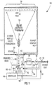
- FIG. 1 is a schematic diagram illustrating a thermo-fogging filtration system in accordance with embodiments of the present disclosure.
- the thermofogging filtration system 100 includes an environmentally sealed storage room 110 (such as a commodity storage room for storing potatoes) is provided for safely treating items within the environmentally sealed storage room 110.
- the environmentally sealed storage room 110 is a substantially closed room that is arranged to substantially reduce the introduction of a substantial amount of treatment substances into the surrounding area.
- Access to the chamber of the environmentally sealed storage room 110 can be provided using access port 112, which is arranged to allow ingress to and egress from the chamber of the environmentally sealed storage room 110 by, for example, humans and/or items 124 to be treated within the environmentally sealed storage room 110.
- the environmentally sealed storage room 110 is any suitable chamber that need not be large enough to allow a human to enter the environmentally sealed storage room 110.
- An airstream substance infuser is arranged to infuse treatment substances into an airstream to generate air-borne treatment substances.
- the airstream substance infuser is arranged to introduce the airstream and the air-borne treatment substances into the volume of air of the substantially closed room to generate dispersed air-borne substances.
- Thermo-fogging gun 120 is an example of an airstream substance infuser that is arranged to infuse treatment substances into an airstream.
- Thermo-fogging gun 120 is coupled to the environmentally sealed storage room 100 via access port 112, which is normally sealed during times in which items 124 within the environmentally sealed storage room 110 are being treated.
- air-borne substances 122 are introduced into the environmentally sealed storage room 110 by directing the airstream through an exhaust port of the thermo-fogging gun 120.
- the air-borne substances 122 disperse after being introduced into the environmentally sealed storage room 110 and come in contact with the items 124 that are to be treated.
- post-harvest chemicals are applied to fruit (or vegetables, including tubers such as potatoes) in sealed storage rooms using a thermo-fogging application method.
- Air and treatment chemicals in a form such as fog is introduced into a storage room (and/or container) using an electrically driven thermo-fogging gun.
- the treatment chemicals are dispersed in the storage room using air currents (such as those caused by the thermo-fogging gun itself and/or circulation fans) and (e.g., naturally occurring) diffusion gradients.
- fan means, for example, a device that causes movement of air.
- the operation is can be continued (without, for example, interruption) over a period of hours (more or less).
- the introduction of air-borne substances 122 into the environmentally sealed storage room 110 can increase the air pressure of the environmentally sealed storage room 110.
- the rise in the air pressure of the environmentally sealed storage room 110 can potentially cause exfiltration of air (and air-borne particles) from the environmentally sealed storage room 110 in accordance with the degree to which the environmentally sealed storage room 110 is, inter alia, airtight.
- the rise in the air pressure of the environmentally sealed storage room 110 can cause a higher back-pressure to exist relative to the exhaust port of the thermo-fogging gun 120, which can cause a reduction in the efficiency of the thermo-fogging gun as well as a reduction in the efficacy of the air-borne substances 122 treatment process.
- An exhaust manifold 140 is provided to prevent a substantial increase in the air pressure of the environmentally sealed storage room 110 (so that, for example, uncontrolled exfiltration is reduced and/or eliminated).
- the exhaust manifold 140 is a plastic tube that is arranged in an area of the environmentally sealed storage room 110 that is at an opposite end of and/or away from the area of the access port 112 such that the air-borne substances traverse a portion of the environmentally sealed storage room 110 that includes items 124 to be treated.
- Vent holes 142 are arranged in the exhaust manifold 140 to permit the introduction of air (including air-borne particles) into the exhaust manifold 140.
- the vent holes 142 are 1.9 cm (three/quarters of an inch) in diameter and are spaced on 45.7 cm (18 inch) centers along a wall of the environmentally sealed storage room 110 that faces the exhaust port of the thermo-fogging gun 120.
- the air pressure developed in the environmentally sealed storage room 110 by the introduction of the air (that conveys the air-borne substances) into the environmentally sealed storage room 110 facilitates the introduction of air (including air-borne particles) into the exhaust manifold 140.
- vent holes 142 along portions of the exhaust manifold 140 (placed along the wall that opposes the exhaust port 112 through which the air-borne substances 122 are introduced into the environmentally sealed storage room 110, for example) promotes a more even dispersion of the air-borne substances throughout the chamber of the environmentally sealed storage room 110.
- the exhaust manifold 140 is coupled to a filter 150 that is arranged to capture a portion (including a portion containing substantially all) of the concentration of air-borne particles that have been introduced into the exhaust manifold 140.
- the filter 150 can be located outside of the environmentally sealed storage room so as to permit easy maintenance and monitoring of the filter 150. (Filter 150 is further described below with reference to FIG. 2 .)
- an in-line duct fan 160 is coupled to the exhaust of filter 150.
- the in-line duct fan 160 is coupled in series with the filter 150 between the exhaust port 112 of the substantially closed room 110 and the exhaust vent 170.
- the exhaust manifold 140 is arranged to receive the dispersed air-borne substances 122 in the volume of air of the substantially closed room 110 and to couple the exhaust air current to the fan 160.
- In-line duct fan 160 is arranged to provide a negative pressure (e.g., suction) to the exhaustive filter 150.
- the applied negative pressure can, for example, be used to reduce the pressure of the filter 150 relative to the ambient air pressure (e.g., the air pressure surrounding the environmentally sealed storage room 110).
- the fan 160 is arranged to induce flow of the exhaust air current from the substantially closed room to the exhaust vent.
- the reduced internal pressure of filter 150 substantially reduces the potential for the air-borne substances to escape from the filter 150 housing by lessening (and/or even reversing) the pressure gradient between the inside of filter 150 and the outside of filter 150.
- the housing of filter 150 is arranged to be opened to permit maintenance of the filter 150 as well as to permit inspections thereof.
- the exhaust of in-line duct fan 160 can be, for example, optionally coupled to another filter. In-line duct fan 160 is coupled in series between the filter 150 and the exhaust vent 170. The exhaust of in-line duct fan 160 can be released as exhaust (through exhaust vent 170) to the ambient air (surrounding environmentally sealed storage room 110).
- Exhaust vent 170 optionally contains a check valve 172 to, for example, permit portions of the system (as described below) to operate at pressures lower than ambient (e.g., gauge) pressure (which normally reduces the possibility of exfiltration of treatment substances into the ambient air).
- a check valve 172 to, for example, permit portions of the system (as described below) to operate at pressures lower than ambient (e.g., gauge) pressure (which normally reduces the possibility of exfiltration of treatment substances into the ambient air).
- thermo-fogger gun 120 is arranged to introduce around 51.0-68.0 cubic metre per hour (30-40 cubic feet per minute (CFM)) of an air/chemical mixture into the environmentally sealed storage room 110 in the form of a fog.
- Controller 180 is arranged to determine ambient pressure (via sensor 182), chamber pressure (via sensor 132), filter intake pressure (via sensor 152), filter exhaust pressure (via sensor 154), and fan exhaust pressure (via sensor 162).
- Controller 180 is arranged to control the storage room pressure to a selected value between (for example) -37.3 and 37.3 Pa (-0.15 and +0.15 inches water column (IWC)) using a differential pressure reading.
- the differential pressure reading can be determined by subtracting a reading from sensor 132 with a (nearly contemporaneous) reading from sensor 182.
- Controller 180 is arranged to control the storage room pressure to a selected value used to control a variable speed in-line duct fan.
- Controller 180 can also determine a flow rate through the filter 150 by determining a differential pressure in response to readings from sensor 152 (at the intake of filter 150) and from sensor 154 (at the exhaust of filter 150).
- An abnormally high pressure differential can indicate a clogged filter (for example) or indicate that service of the filter is to be performed.
- Pressure sensor 162 can be used in combination other pressure sensors (such as sensor 154) to determine the efficiency of in-line duct fan 160, a blockage of the exhaust manifold upstream or downstream of the sensor 162, and normalization and/or calibration of other sensors.
- controller 180 is optionally arranged to selectively couple one (or more simultaneously) of intakes 182, 184, and 186 to the gun intake 188.
- intake 182 air from the volume of air (including air-borne treatment substances, if any) from environmentally sealed room 110 can be recirculated for injection of additional air-borne treatment substances into the environmentally sealed room. Recirculation via intake 182, for example, extends the life of filter 150, and reduces the possibility that the air-borne substances (not captured by filter 150) might be released to the surrounding area.
- air exhausted from the filter 150 can be recirculated for injection of additional air-borne treatment substances into the environmentally sealed room.
- the controller 180 can vary the pressure in selected areas.
- the pressure of the volumes measured by sensors 152, 154, and 162 can be controlled by selectively controlling the relative speeds of an intake fan of gun 120 and fan 160.
- the air pressures in between the exhaust of gun 120 and the intake of fan are lowered.
- the pressures at points measured by sensors 152, 154, and 162 can be reduced-even to pressures below ambient pressure (which reduces the possibility of exfiltration of the treatment substances to the ambient air).
- the pressure of the volumes measured by sensors 152, 154, and 162 can be controlled by selectively controlling the relative speed of one or both of fan of gun 120 and fan 160.
- intake 186 (for example) can be selectively opened using a range of settings from a fully open to a fully closed position. (In another exemplary embodiment, check valve 172 can be controlled in a similar fashion).
- ambient air is used for by the gun 120 for injection of additional air-borne treatment substances into the environmentally sealed room.
- the fan 160 is used to motivate air flow in the exhaust manifold, to draw the air-borne substances through filter 150, and to exhaust the filtered air through vent 170 as described above.
- the possibility of exfiltration of air-borne substances from the environmentally sealed storage room 110 is reduced, the possibility of exfiltration of air-borne substances from portions of the exhaust manifold 140 and filter 150 is reduced, and the dispersion of the air-borne substances in the environmentally sealed storage room 110 is more evenly distributed in accordance with the distribution of vent holes 142.
- FIG. 2 is an isometric view illustrating a filter system in accordance with embodiments of the present disclosure.
- the filter system 200 includes a chamber 210 having a width W (e.g., 40.6 cm (16 inches)), a height H (e.g., 63.5 cm (25 inches)), and a depth D (e.g., 50.8 cm (20 inches)).
- Intake port 220 is arranged to accept an air current 222, which contains air-borne substances that are to be filtered (e.g., removed) by filter system 200.
- the air current 222 is coupled to chamber 210 via intake port 220, and after being filtered as described below, is exhausted via exhaust port 250.
- Fan 260 is arranged to motivate the passage of air current 222 through filters of the chamber 210 by evacuating air (in varying degrees as described above) from the chamber 110 and exhausting the evacuated air as air current 272.
- Chamber 210 has a first stage filter 230 and a second stage filter 240.
- the first stage filter 230 in an embodiment is a bank of six "3M" high particle-rated fiber air filters (such as model number 1900 or 2200 and having dimensions of 2.5 cm (one inch) deep by 50.8 cm (20 inches) wide by 63.5 cm (25 inches) high) that are arranged in series with respect to the air current flow (such that the air current passes through each fiber air filter in the bank in turn).
- the first stage filter 230 includes a first filter bank that is arranged to capture an active ingredient of the air-borne substances, for example, a series (bank) of pleated fiber filters that are arranged to filter out "visible" air-borne particles.
- the air-borne particles typically include an active ingredient (AI) used for treating, for example, the items 124 in the environmentally sealed storage room.
- the first stage filter 230 includes one or more individual filters arranged in a bank.
- the second stage filter 240 in an embodiment is a column activated carbon 12 x 30 mesh (e.g., 1.68 mm x 0.595 mm) filter (having outer dimensions of 5.1 cm (two inches) deep by 50.8 cm (20 inches) wide by 63.5 cm (25 inches) high).
- the second stage filter 240 is coupled between the first filter 230 and the fan 260 and is arranged to capture organic solvents of the air-borne substances such as volatile solvents and odor ("non-visible" air-borne particles) present in the air current 222.
- the second stage filter 240 can include one or more individual filters arranged in a bank.
- the efficiency of the filter system 200 can be made by performing measurements on the quality of the intake air as well as performing measurements on the quality of the exhaust (e.g., filtered) air.
- inspection ports 224 and 254 are respectively provided to, for example, to sample the intake air and the exhaust air.
- the inspection ports 224 and 254 are used to provide a substantially airtight aperture that is arranged to accept a sampling probe.
- the inspection ports 224 and 254 can each include a substantially sealed membrane through which a needle of syringes 226 and 256 is respectively inserted.
- substantially sealed or airtight are used, for example, to indicate a level at which exfiltration of air-borne substances and/or infiltration of air from the sampling ports would introduce an unacceptable level of error in the measurements.
- Measurements on the quality of the intake air and exhaust air can be performed by measuring by sampling the concentrations of active ingredient (AI) pre-filter (e.g., via inspection port 224) and post-filter (e.g., via inspection port 254). Concentration measurements can be performed by taking aerosol samples at intervals starting, for example, around five to 10 minutes after the beginning of the fogging process (which typically includes introducing treatment substances into the environmentally sealed storage room 110 as described above).
- a first 60 ml-syringe is used to draw a 50 ml sample via inspection port 224 (pre-filter) and a second 60 ml-syringes is used to draw a 50 ml sample via inspection port 254 (post-filter).
- a 50 ml sample can be drawn by insert the needle into an inspection port and the plunger slowly drawn back (e.g., pulled up) to the 60 ml mark. After a 10 second delay, the plunger is depressed (e.g., pushed down) to 50 ml mark.
- the syringe is extracted from the inspection port and used to draw 5 ml of a solvent (such as analytical grade ethyl acetate) into the syringe.
- the aerosol sample and the solvent are mixed by, for example, removing the needle, capping the syringe outlet, and vigorously shaking the syringe for around 30 seconds.
- the plunger depressed to expel the liquid content (include solvent and solutes) into sampling vials.
- the level of the active ingredient content of the liquid content in the sampling vials can be determined using a suitable gas chromatography- (GC-) based method.
- the efficiency of the filter can be determined by comparing the higher concentration of AI in the pre-filter aerosol sample with the (usually lower) concentration (if any) of AI in a corresponding post-filter aerosol sample. For more accurate determinations, the samples are to be drawn contemporaneously (or substantially contemporaneously) compared to the corresponding outlet sample.
- Table 1 is a summary of capture efficiencies of various filters tested: TABLE 1 Filter Material Al (mg) /m ⁇ 3 min Pyre thrin /m ⁇ 3 max Pyre thrin /m ⁇ 3 avg AI re duction min % AI re duction max % AI re duction avg % Wgt gain (9) (6) 20" X 25" 3M 2200 air filters + 2" carbon 0 0 0 100 100 100 1074 (6) 20" X 25" 3M 2200 air filters + 2" carbon 0 0 0 100 100 100 1121 (6) 20" X 25" 3M 1900 rated fiber air filter 0.1 7.7 4 99.7 100 99.85 266 (6) 20" X 25" 3M 1900 rated fiber air filter 1 9 4 99.3 99.8 99.6 497 (6) 20" X 25" 3M 1900 rated fiber air filter *after 1 room* 3 33 13 90.6 99.4 97 (6) 3M 1900 rated fiber air filter (“Mer
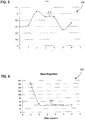
- FIG. 3 is a plot diagram that illustrates the efficiency of a "3M" filter bank used in a thermo-fogging filtration system in accordance with embodiments of the present disclosure.
- Chart 300 includes a plot 310, which illustrate a percentage of weight gain of each "3M" filter of a filter bank (for example) used in an exemplary thermo-fogger filtration system having a total "fog" application time of 45 minutes.
- Table 2 is a summary of the weight gain of the "3M" filters tested (due to air-borne substances being captured by each filter, for example): TABLE 2 Filters Weight (g) # Before After ⁇ m % W. Gain 1 275.98 730.5 454.52 164.7 2 278.19 509.29 231.1 83.1 3 271.49 415.21 143.72 52.9 4 271.21 374.49 103.28 38.1 5 271.16 339.58 68.42 25.2 6 271.12 306.63 35.51 13.1 Total 1639.15 2675.7 1036.55 63.2
- Table 3 is a summary of an analysis of the aerosol reduction in a thermo-fogging filtration system using "3M" filters tested: TABLE 3 Aerosol Analysis Sampling Time (min) Pre-Filter mg Pyr./M 3 After-Filter mg Pyr./M 3 AI Reduction (Times) % Reduction 5 min 508.83 24.32 21 times 95.2 25 min 4891.2 452.969 11 times 90.7
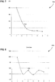
- FIG. 4 is a plot diagram that illustrates the efficiency of a "well-sealed 3M" filter bank used in a thermo-fogging filtration system in accordance with embodiments of the present disclosure.
- Chart 400 includes a plot 410, which illustrate a percentage of weight gain of each "well-sealed 3M" filter of a filter bank (for example) used in an exemplary thermo-fogger filtration system having a total "fog" application time of 135 minutes.
- Table 4 is a summary of the weight gain of the "well-sealed 3M" filters tested (due to air-borne substances being captured by each filter, for example): TABLE 4 Filters Weight (g) # Before After ⁇ m % W. Gain 1 274.53 768.15 493.62 179.8 2 273.94 536.91 262.97 96.0 3 275.63 454.37 178.74 64.8 4 275.68 398.83 123.15 44.7 5 271.67 362.18 90.51 33.3 6 272.15 324.3 52.15 19.2 Total 1643.6 2844.74 1201.14 73.1
- Table 5 is a summary of an analysis of the aerosol reduction in a thermo-fogging filtration system using "well-sealed 3M" filters tested: TABLE 5 Aerosol Analysis Sampling Time (min) Pre-Filter mg Pyr./M 3 After-Filter mg Pyr./M 3 AI Reduction (Times) % Reduction 5 min 4311.0 113.7 37.9 97.4 10 min 3610.8 72.6 49.8 98.0 20 min 4010.0 71.4 56.1 98.2 35 min 3244.4 191.2 17.0 94.1 70 min 2521.3 55.9 45.1 97.8 125 min 1592.1 67.2 23.7 95.8
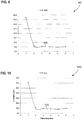
- FIG. 5 is a plot diagram that illustrates the efficiency of a "cheap" filter bank used in a thermo-fogging filtration system in accordance with embodiments of the present disclosure.
- Chart 500 includes a plot 510, which illustrate a percentage of weight gain of each "cheap" filter of a filter bank (for example) used in an exemplary thermo-fogger filtration system having a total "fog" application time of 15 minutes.
- Table 6 is a summary of the weight gain of the "cheap" filters tested (due to air-borne substances being captured by each filter, for example): TABLE 6 Filters Weight (g) # Before After ⁇ m % W. Gain 1 130.67 131.3 0.63 0.5 2 131.32 132.39 1.07 0.8 3 134.52 131.43 0.91 0.7 4 130.9 131.8 0.9 0.7 5 130.14 130.64 0.5 0.4 6 131.09 131.8 0.71 0.5 Total 784.64 789.36 4.72 0.6
- Table 7 is a summary of an analysis of the aerosol reduction in a thermo-fogging filtration system using "cheap" filters tested: TABLE 7 Aerosol Analysis Sampling Time (min) Pre-Filter mg Pyr./M 3 After-Filter mg Pyr./M 3 AI Reduction (Times) % Reduction 5 min 787.7 735.4 1.1 6.6
- FIG. 6 is a plot diagram that illustrates the efficiency of a "reusable" filter bank used in a thermo-fogging filtration system in accordance with embodiments of the present disclosure.
- Chart 600 includes a plot 610, which illustrate a percentage of weight gain of each "reusable" filter of a filter bank (for example) used in an exemplary thermo-fogger filtration system having a total "fog" application time of 165 minutes.
- Table 8 is a summary of the weight gain of the "reusable" filters tested (due to air-borne substances being captured by each filter, for example): TABLE 8 Filters Weight (g) # Before After ⁇ m % W. Gain 1 581.56 749.52 167.96 28.9 2 584.4 631.4 47 8.0 3 584.07 623.05 38.98 6.7 4 579.89 618.92 39.03 6.7 5 580.45 616.72 36.27 6.2 6 583.79 622.38 38.59 6.6 Total 3494.16 3861.99 367.83 10.5
- Table 9 is a summary of an analysis of the aerosol reduction in a thermo-fogging filtration system using "reusable" filters tested: TABLE 9 Aerosol Analysis Sampling Time (min) Pre-Filter mg Pyr./M 3 After-Filter mg Pyr./M 3 AI Reduction (Times) % Reduction 5 1889.9 1641.4 1.2 13.1 20 2989.2 1516.9 2.0 49.3 50 1985.5 810.4 2.5 59.2 95 750 530 1.4 29.3 155 500 210 2.4 58.0
- FIG. 7 is a plot diagram that illustrates the efficiency of a "cheap (2 nd test)" filter bank used in a thermo-fogging filtration system in accordance with embodiments of the present disclosure.
- Chart 700 includes a plot 710, which illustrate a percentage of weight gain of each "cheap (2 nd test)" filter of a filter bank (for example) used in an exemplary thermo-fogger filtration system having a total "fog" application time of 152 minutes.
- Table 10 is a summary of the weight gain of the "cheap (2 nd test)" filters tested (due to air-borne substances being captured by each filter, for example): TABLE 10 Filters Weight (g) # Before After ⁇ m % W. Gain 1 126.59 328.27 201.68 159.3 2 125.07 224.5 99.43 79.5 3 126.65 170.16 43.51 34.4 4 125.06 154.4 29.34 23.5 5 129.27 158.1 28.83 22.3 6 122.5 145.96 23.46 19.2 Total 755.14 1181.39 426.25 56.4
- Table 11 is a summary of an analysis of the aerosol reduction in a thermo-fogging filtration system using "cheap (2 nd test)" filters tested: TABLE 11 Aerosol Analysis Sampling Time (min) Pre-Filter mg Pyr./M 3 After-Filter mg Pyr./M 3 AI Reduction (Times) % Reduction 7 2784 2600 1.1 6.6 27 1332 1570 0.8 -17.9 47 1715 180 9.5 89.5 72 1203 130 9.3 89.2 112 491 70 7.0 85.7 142 315 50 6.3 84.1
- FIG. 8 is a plot diagram that illustrates the efficiency of a "reusable filters pretreated with propylene glycol” (PG) filter bank used in a thermo-fogging filtration system in accordance with embodiments of the present disclosure.
- Chart 800 includes a plot 810, which illustrate a percentage of weight gain of each "reusable filters pretreated with PG" filter of a filter bank (for example) used in an exemplary thermo-fogger filtration system having a total "fog" application time of 165 minutes.
- PG propylene glycol
- Table 12 is a summary of the weight gain of the "reusable filters pretreated with PG" filters tested (due to air-borne substances being captured by each filter, for example): TABLE 12 Filters Weight (g) # Before After ⁇ m PG on fltr % W. Gain 1 643.65 800.4 156.75 48.91 19.6 2 642.81 677.4 34.59 54.78 5.1 3 619.7 671.75 52.05 34.1 7.7 4 627.5 655.07 27.57 94.7 4.2 5 629.3 683.96 54.66 45.7 8.0 6 643.95 690.3 46.35 58.22 6.7 Total 3806.91 4178.88 371.97 336.41 8.9
- Table 13 is a summary of an analysis of the aerosol reduction in a thermo-fogging filtration system using "reusable filters pretreated with PG" filters tested: TABLE 13 Aerosol Analysis Sampling Time (min) Pre-Filter mg Pyr./M 3 After-Filter mg Pyr./M 3 AI Reduction (Times) % Reduction 5 1220 990 1.2 18.9 25 2550 1840 1.4 27.8 45 2330 970 2.4 58.4 85 1690 50D 3.4 70.4 145 1660 19D 8.7 88.6
- thermo-fogging filtration system The efficiency of an "activated carbon 15.2 cm (six inches)" filter used in a thermo-fogging filtration system in accordance with embodiments of the present disclosure is now discussed.
- Tables 14 and 15 illustrate measurements taken when using an "activated carbon 15.2 cm (six inches)" filter (for example) used in an exemplary thermo-fogger filtration system having a total "fog" application time of 125 minutes.
- Table 14 is a summary of the weight gain of the "activated carbon 15.2 cm (six inches)" filters tested (due to air-borne substances being captured by each filter, for example): TABLE 14 Filters Weight (g) # Before After ⁇ m % W. Gain 1 20411.7 21346.1 934.4 4.6 Total 20411.7 21346.1 934.4 4.6
- Table 15 is a summary of an analysis of the aerosol reduction in a thermo-fogging filtration system using "activated carbon 15.2 cm (six inches)" filters tested: TABLE 15 Aerosol Analysis Sampling Time (min) Pre-Filter mg Pyr./M 3 After-Filter mg Pyr./M 3 AI Reduction (Times) % Reduction 5 770 580 1.3 24.7 35 3030 90 33.7 97.0 65 1940 70 27.7 96.4 95 770 40 19.3 94.8 125 350 50 7.0 85.7
- Table 16 is a summary of the weight gain of the "activated carbon 15.2 cm (six inches) (pretreated)" filters tested (due to air-borne substances being captured by each filter, for example): TABLE 16 Filters Weight (g) # Before After ⁇ m % W. Gain 1 23586.8 24335.2 748.4 3.2 Tot 23586.B 24335.2 748.4 3.2
- Table 17 is a summary of an analysis of the aerosol reduction in a thermo-fogging filtration system using "activated carbon 15.2 cm (six inches) (pretreated)" filters tested: TABLE 17 Aerosol Analysis Sampling Time (min) Pre-Filter mg Pyr./M 3 After-Filter mg Pyr./M 3 AI Reduction (Times) % Reduction 5 2140 920 2.3 57.0 35 1830 230 8.0 87.4 65 1310 50 26.2 96.2 95 540 50 10.8 90.7 125 260 30 8.7 88.5
- FIG. 9 is a plot diagram that illustrates the efficiency of a "carbon/fiber filter (untreated)" filter bank used in a thermo-fogging filtration system in accordance with embodiments of the present disclosure.
- Chart 900 includes a plot 910, which illustrate a percentage of weight gain of each "carbon/fiber filter (untreated)" filter of a filter bank (for example) used in an exemplary thermo-fogger filtration system having a total "fog" application time of 125 minutes.
- Table 18 is a summary of the weight gain of the "carbon/fiber filter (untreated)" filters tested (due to air-borne substances being captured by each filter, for example): TABLE 18 Filters Weight (g) # Before After ⁇ m % W. Gain 1 239.73 417.67 177.94 74.2 2 240.6 271.39 30.79 12.8 3 239.56 265.13 25.57 10.7 4 244.23 268.52 24.29 9.9 5 238.55 260.86 22.31 9.4 6 237.39 260.61 23.22 9.8 Total 1440.06 1744.18 304.12 21.1
- Table 19 is a summary of an analysis of the aerosol reduction in a thermo-fogging filtration system using "carbon/fiber filter (untreated)" filters tested: TABLE 19 Aerosol Analysis Sampling Time (min) Pre-Filter mg Pyr./M 3 After-Filter mg Pyr./M 3 AI Reduction (Times) % Reduction 5 180 130 1.4 27.8 35 3090 1730 1.8 44.0 65 2060 940 2.2 54.4 95 640 380 0.6 40.6 125 240 150 1.6 37.5
- FIG. 10 is a plot diagram that illustrates the efficiency of a "carbon/fiber filter (10% PG)" filter bank used in a thermo-fogging filtration system in accordance with embodiments of the present disclosure.
- Chart 1000 includes a plot 1010, which illustrate a percentage of weight gain of each "carbon/fiber filter (10% PG)" filter of a filter bank (for example) used in an exemplary thermo-fogger filtration system having a total "fog" application time of 125 minutes.
- Table 20 is a summary of the weight gain of the "carbon/fiber filter (10% PG)" filters tested (due to air-borne substances being captured by each filter, for example): TABLE 20 Filters Weight (g) # Before After ⁇ m % W. Gain 1 261.2 421.31 160.11 61.3 2 263.74 291.9 28.16 10.7 3 264.44 289.9 25.46 9.6 4 265.11 288.31 23.2 8.8 5 264.13 285.17 21.04 8.0 6 269.35 295.75 26.4 9.8 Total 1587.97 1872.34 284.37 17.9
- Table 21 is a summary of an analysis of the aerosol reduction in a thermo-fogging filtration system using "carbon/fiber filter (10% PG)" filters tested: TABLE 21 Aerosol Analysis Sampling Time (min) Pre-Filter mg Pyr./M 3 After-Filter mg Pyr./M 3 AI Reduction (Times) % Reduction 5 580 150 3.9 74.1 35 3490 1740 2.0 50.1 65 2060 940 2.2 54.4 95 770 400 1.9 48.1 125 340 120 2.8 64.7
- FIG. 11 is a plot diagram that illustrates the efficiency of a "3M filter (Second Test)" filter bank used in a thermo-fogging filtration system in accordance with embodiments of the present disclosure.
- Chart 1100 includes a plot 1110, which illustrate a percentage of weight gain of each "3M filter (Second Test)" filter of a filter bank (for example) used in an exemplary thermo-fogger filtration system having a total "fog" application time of 140 minutes.
- Table 22 is a summary of the weight gain of the "3M filter (Second Test)" filters tested (due to air-borne substances being captured by each filter, for example): TABLE 22 Filters Weight (g) # Before After ⁇ m % W. Gain 1 273.13 722.62 449.49 164.6 2 271.97 522.04 250.07 91.9 3 274.07 452.04 177.97 64.9 4 2737 409.77 136.07 49.7 5 271.01 355.75 84.74 31.3 6 271.08 315.8 44.72 16.5 Total 1634.96 2778.02 1143.06 69.9
- Table 23 is a summary of an analysis of the aerosol reduction in a thermo-fogging filtration system using "3M filter (Second Test)" filters tested: TABLE 23 Aerosol Analysis Sampling Time (min) Pre-Filter mg Pyr./M 3 After-Filter mg Pyr./M 3 AI Reduction (Times) % Reduction 5 970 80 12.1 91.8 35 1530 130 11.8 91.5 65 1120 90 12.4 92.0 95 340 110 3.1 67.6 125 160 80 2.0 50.0 135 360 40 9.0 88.9
- FIG. 12 is a plot diagram that illustrates the efficiency of a "3M filter (washed and dried)" filter bank used in a thermo-fogging filtration system in accordance with embodiments of the present disclosure.
- Chart 1100 includes a plot 1110, which illustrate a percentage of weight gain of each "3M filter (washed and dried)" filter of a filter bank (for example) used in an exemplary thermo-fogger filtration system having a total "fog" application time of 125 minutes.
- Table 24 is a summary of the weight gain of the "3M filter (washed and dried)" filters tested (due to air-borne substances being captured by each filter, for example): TABLE 24 Filters Weight (g) # Before After ⁇ m % W. Gain 1 276.45 701.69 425.24 153.8 2 290.66 466.66 176 60.6 3 295 417.88 122.86 41.7 4 299.72 384.53 84.81 28.3 5 313.3 375.82 62.52 20.0 6 375.2 404.6 29.4 7.8 Total 1850.33 2751.18 900.85 48.7
- Table 25 is a summary of an analysis of the aerosol reduction in a thermo-fogging filtration system using "3M filter (washed and dried)" filters tested: TABLE 25 Aerosol Analysis Sampling Time (min) Pre-Filter mg Pyr./M 3 After-Filter mg Pyr./M 3 AI Reduction (Times) % Reduction 5 520 90 5.8 82.7 35 2200 230 9.6 89.5 65 1870 140 13.4 92.5 95 860 120 7.2 86.0 125 360 150 2.4 58.3
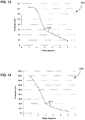
- FIG. 13 is a plot diagram that illustrates the efficiency of a "two cheap and four 3M filters" filter bank used in a thermo-fogging filtration system in accordance with embodiments of the present disclosure.
- Chart 1300 includes a plot 1310, which illustrate a percentage of weight gain of each "two cheap and four 3M filters" filter of a filter bank (for example) used in an exemplary thermo-fogger filtration system having a total "fog" application time of 125 minutes.
- Table 26 is a summary of the weight gain of the "two cheap and four 3M filters" filters tested (due to air-borne substances being captured by each filter, for example): TABLE 26 Filters Weight (g) # Before After ⁇ m % W. Gain 1 126.42 311.21 184.79 146.2 2 123.35 290.91 167.56 135.8 3 274.17 447.07 172.9 63.1 4 275.67 402.02 126.35 45.8 5 276.46 360.24 83.78 30.3 6 276.33 324.74 48.41 17.5 Total 1352.4 2136.19 783.79 58.0
- Table 27 is a summary of an analysis of the aerosol reduction in a thermo-fogging filtration system using "two cheap and four 3M filters" filters tested: TABLE 27 Aerosol Analysis Sampling Time (min) Pre-Filter mg Pyr./M 3 After-Filter mg Pyr./M 3 AI Reduction (Times) % Reduction 5 1790 80 22.4 95.5 35 1330 60 22.2 95.5 65 950 40 23.8 95.8 95 290 50 5.8 82.8 125 540 40 13.5 92.6
- FIG. 14 is a plot diagram that illustrates the efficiency of a "two cheap and four 3M filters (reused)" filter bank used in a thermo-fogging filtration system in accordance with embodiments of the present disclosure.
- Chart 1400 includes a plot 1410, which illustrate a percentage of weight gain of each "two cheap and four 3M filters (reused)" filter of a filter bank (for example) used in an exemplary thermo-fogger filtration system having a total "fog" application time of 125 minutes.
- Table 28 is a summary of the weight gain of the "two cheap and four 3M filters (reused)" filters tested (due to air-borne substances being captured by each filter, for example): TABLE 28 Filters Weight (g) # Before After ⁇ m % W. Gain 1 123.26 316.59 193.33 156.8 2 130.54 274.26 143.72 110.1 3 324.74 468.45 143.71 44.3 4 360.24 449.26 89.02 24.7 5 402.02 453.92 51.9 12.9 6 447.07 483.53 36.46 8.2 Total 1787.87 2446.01 658.14 36.8
- Table 29 is a summary of an analysis of the aerosol reduction in a thermo-fogging filtration system using "two cheap and four 3M filters (reused)" filters tested: TABLE 29 Aerosol Analysis Sampling Time (min) Pre-Filter mg Pyr./M 3 After-Filter mg Pyr./M 3 AI Reduction (Times) % Reduction 5 940 510 1.8 45.7 35 2740 390 7.0 85.8 65 640 80 8.0 87.5 95 620 70 8.9 88.7 125 400 60 6.7 85.0
- FIG. 15 is a plot diagram that illustrates the efficiency of a "20x25 3M filters (new)" filter bank used in a thermo-fogging filtration system in accordance with embodiments of the present disclosure.
- Chart 1500 includes a plot 1510, which illustrate a percentage of weight gain of each "20x25 3M filters (new)" filter of a filter bank (for example) used in an exemplary thermo-fogger filtration system having a total "fog" application time of 125 minutes.
- Table 30 is a summary of the weight gain of the "20x25 3M filters (new)" filters tested (due to air-borne substances being captured by each filter, for example): TABLE 30 Filters Weight (g) # Before After ⁇ m % W. Gain 1 302.25 751 448.75 148.5 2 301.82 556.5 254.68 84.4 3 339.90 532.35 192.54 56.6 4 301.25 385.84 84.59 28.1 5 303.84 332.1 28.26 9.3 6 302.92 315.63 12.71 4.2 Total 1851.98 2873.42 1021.44 55.2
- Table 31 is a summary of an analysis of the aerosol reduction in a thermo-fogging filtration system using "20x25 3M filters (new)" filters tested: TABLE 31 Aerosol Analysis Sampling Time (min) Pre-Filter mg Pyr./M 3 After-Filter mg Pyr./M 3 AI Reduction (Times) % Reduction 5 960 50 19.2 94.8 35 2100 40 52.5 98.1 65 480 60 8.0 87.5 95 390 60 6.5 84.6 125 210 40 5.3 81.0
- FIG. 16 is a plot diagram that illustrates the efficiency of a "20x25 3M filters (reused)" filter bank used in a thermo-fogging filtration system in accordance with embodiments of the present disclosure.
- Chart 1600 includes a plot 1610, which illustrate a percentage of weight gain of each "20x25 3M filters (reused)" filter of a filter bank (for example) used in an exemplary thermo-fogger filtration system having a total "fog" application time of 100 minutes.
- Table 32 is a summary of the weight gain of the "20x25 3M filters (reused)" filters tested (due to air-borne substances being captured by each filter, for example): TABLE 32 Filters Weight (g) # Before After ⁇ m % W. Gain 1 315.63 759.3 443.67 140.6 2 332.1 575.72 243.62 73.4 3 385.84 592.72 206.88 53.6 4 532.35 501.64 -30.71 -5.8 5 556.5 559.66 3.16 0.6 6 751 750.17 -0.83 -0.1 Total 2873.42 3739.21 865.79 30.1
- Table 33 is a summary of an analysis of the aerosol reduction in a thermo-fogging filtration system using "20x25 3M filters (reused)" filters tested: TABLE 33 Aerosol Analysis Sampling Time (min) Pre-Filter mg Pyr./M 3 After-Filter mg Pyr./M 3 AI Reduction (Times) % Reduction 5 500 70 7.1 86.0 35 2090 160 13.1 92.3 65 880 150 5.9 83.0 95 540 90 6.0 83.3
- thermo-fogging filtration system The efficiency of an "activated carbon (large granules) 20x20x6" filter used in a thermo-fogging filtration system in accordance with embodiments of the present disclosure is now discussed.
- Tables 34 and 35 illustrate measurements taken when using an "activated carbon (large granules) 20x20x6" filter (for example) used in an exemplary thermo-fogger filtration system having a total "fog" application time of 125 minutes.
- Table 34 is a summary of the weight gain of the "activated carbon (large granules) 20x20x6" filters tested (due to air-borne substances being captured by each filter, for example): TABLE 34 Filters Weight (g) # Before After ⁇ m % W. Gain 1 17345.37 18198.1 852.8 4.9 Total 17345.4 18198.1 852.8 4.9
- Table 35 is a summary of an analysis of the aerosol reduction in a thermo-fogging filtration system using "activated carbon (large granules) 20x20x6" filters tested: TABLE 35 Aerosol Analysis Sampling Time (min) Pre-Filter mg Pyr./M 3 After-Filter mg Pyr./M 3 AI Reduction (Times) % Reduction 5 910 880 1.0 3.3 35 2110 400 5.3 81.0 65 1370 240 5.7 82.5 95 430 240 1.8 44.2 125 160 90 1.8 43.8
- thermo-fogging filtration system The efficiency of an "activated carbon (large granules) 20x20x12" filter used in a thermo-fogging filtration system in accordance with embodiments of the present disclosure is now discussed.
- Tables 36 and 37 illustrate measurements taken when using an "activated carbon (large granules) 20x20x12" filter (for example) used in an exemplary thermo-fogger filtration system having a total "fog" application time of 205 minutes.
- Table 36 is a summary of the weight gain of the "activated carbon (large granules) 20x20x12" filters tested (due to air-borne substances being captured by each filter, for example): TABLE 36 Filters Weight (g) # Before After ⁇ m % W. Gain 1 55905.26 56744.4 839.1 1.5 Total 55905.3 56744.4 839.1 1.5
- Table 37 is a summary of an analysis of the aerosol reduction in a thermo-fogging filtration system using "activated carbon (large granules) 20x20x12" filters tested: TABLE 37 Aerosol Analysis Sampling Time (min) Pre-Filter mg Pyr./M 3 After-Filter mg Pyr./M 3 AI Reduction (Times) % Reduction 5 1080 780 1.4 27.8 45 520 460 1.1 11.5 85 320 190 1.7 40.6 125 130 120 1.1 7.7 165 110 100 1.1 9.1 205 60 60 1.0 0.0
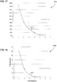
- FIG. 17 is a plot diagram that illustrates the efficiency of a "20x25 3M filters (1900 EcoFOG 11)" filter bank used in a thermo-fogging filtration system in accordance with embodiments of the present disclosure.
- Chart 1700 includes a plot 1710, which illustrate a percentage of weight gain of each "20x25 3M filters (1900 EcoFOG 11)" filter of a filter bank (for example) used in an exemplary thermo-fogger filtration system having a total "fog" application time of 125 minutes.
- Table 38 is a summary of the weight gain of the "20x25 3M filters (1900 EcoFOG 11)" filters tested (due to air-borne substances being captured by each filter, for example): TABLE 38 Filters Weight (g) # Before After ⁇ m % W. Gain 1 338.35 971.6 633.25 187.2 2 313.66 577.78 264.12 84.2 3 311.55 444.85 133.3 42.8 4 311.76 367.11 55.35 17.8 5 298.76 316.28 17.52 5.9 6 302.62 320.26 17.64 5.8 Total 1876.7 2997.88 1121.18 59.7
- Table 39 is a summary of an analysis of the aerosol reduction in a thermo-fogging filtration system using "20x25 3M filters (1900 EcoFOG 11)" filters tested: TABLE 39 Aerosol Analysis Sampling Time (min) Pre-Filter mg Pyr./M 3 After-Filter mg Pyr./M 3 AI Reduction (Times) % Reduction 5 734.40 0 734.0 100.0 35 3369.0 21.8 154.9 99.4 65 938.0 5.0 188.0 99.5 95 173.5 4.4 39.0 97.4 125 125.3 0.0 125.3 100.0 155 24.31 8.8 2.7 63.6
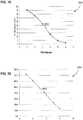
- FIG. 18 is a plot diagram that illustrates the efficiency of a "20x25 3M filters (1900 Melted DPA)" filter bank used in a thermo-fogging filtration system in accordance with embodiments of the present disclosure.
- Chart 1800 includes a plot 1810, which illustrate a percentage of weight gain of each "20x25 3M filters (1900 Melted DPA)" filter of a filter bank (for example) used in an exemplary thermo-fogger filtration system having a total "fog" application time of 125 minutes.
- Table 40 is a summary of the weight gain of the "20x25 3M filters (1900 Melted DPA)" filters tested (due to air-borne substances being captured by each filter, for example): TABLE 40 Filters Weight (g) # Before After ⁇ m % W.Gain 1 308.43 494.29 185.86 60.3 2 307.78 365.9 58.12 18.9 3 303.5 321.56 18.06 6.0 4 305.73 308.84 3.11 1.0 5 308.2 308.98 0.78 0.3 6 307.2 307.61 0.41 0.1 Total 1840.84 2107.18 266.34 14.5
- Table 41 is a summary of an analysis of the aerosol reduction in a thermo-fogging filtration system using "20x25 3M filters (1900 Melted DPA)" filters tested: TABLE 41 Aerosol Analysis Sampling Time (min) Pre-Filter mg Pyr./M 3 After-Filter mg Pyr./M 3 AI Reduction (Times) % Reduction 5 850 1.85 459.5 99.8 35 3740 10 374.0 99.7 65 3120 7.74 403.1 99.8 95 1950 0.1 19500.0 100.0 125 760 0.1 7600.0 100.0
- FIG. 19 is a plot diagram that illustrates the efficiency of a "20x25 3M filters (1900 new EcoFOG 100)" filter bank used in a thermo-fogging filtration system in accordance with embodiments of the present disclosure.
- Chart 1900 includes a plot 1910, which illustrate a percentage of weight gain of each "20x25 3M filters (1900 new EcoFOG 100)" filter of a filter bank (for example) used in an exemplary thermo-fogger filtration system having a total "fog" application time of 119 minutes.
- Table 42 is a summary of the weight gain of the "20x25 3M filters (1900 new EcoFOG 100)" filters tested (due to substances being captured by each filter, for example): TABLE 42 Filters Weight (g) # Before After ⁇ m % W. Gain 1 306.6 446.2 139.6 45.5 2 306.1 422.4 116.3 38.0 3 304 386.1 82.1 27.0 4 306.2 346.5 40.3 13.2 5 304.4 318.1 13.7 4.5 6 305 3100 5 4.6 Total 1832.3 2229.3 397 21.7
- Table 43 is a summary of an analysis of the aerosol reduction in a thermo-fogging filtration system using "20x25 3M filters (1900 new EcoFOG 100)" filters tested: TABLE 43 Aerosol Analysis Sampling Time (min) Pre-Filter mg Pyr./M 3 After-Filter mg Pyr./M 3 AI Reduction (Times) % Reduction 5 531.0 175.0 3.0 67.0 30 935.0 128.0 7.3 86.3 60 1023.0 138.0 7.4 86.5 90 903.0 139.0 6.5 84.6 119 946.0 137.0 6.9 85.5
- FIG. 20 is a plot diagram that illustrates the efficiency of a "20x25 3M filters (1900 new EcoFOG 100)" filter bank used in a thermo-fogging filtration system in accordance with embodiments of the present disclosure.
- Chart 2000 includes a plot 2010, which illustrate a percentage of weight gain of each "20x25 3M filters (1900 new EcoFOG 100)" filter of a filter bank (for example) used in an exemplary thermo-fogger filtration system having a total "fog" application time of 65 minutes in a first room and 80 in a second room.
- Table 44 is a summary of the weight gain of the "20x25 3M filters (1900 new EcoFOG 100)" filters after being used for filtering both rooms (sequentially): TABLE 44 Filters Weight (g) # Before After ⁇ m % W. Gain 1 308.58 530 221.42 71.8 2 309.97 499.6 189.63 61.2 3 309.74 460.1 150.36 48.5 4 310.56 424.4 113.84 36.7 5 307.53 380.3 72.77 23.7 6 309.12 347.7 38.58 12.5 Total 1855.5 2642.1 786.6 42.4
- Table 45 is a summary of an analysis of the aerosol reduction in a thermo-fogging filtration system using "20x25 3M filters (1900 new EcoFOG 100)" filters tested in the first room: TABLE 45 Aerosol Analysis Sampling Time (min) Pre-Filter mg Pyr./M 3 After-Filter mg Pyr./M 3 AI Reduction (Times) % Reduction 5 351.0 33.0 10.5 90.6 20 830.0 6.0 138.3 99.3 35 517.0 3.0 172.3 99.4 50 868.0 6.0 1447 99.3 65 534.0 17.0 31.4 96.8
- Table 46 is a summary of an analysis of the aerosol reduction in a thermo-fogging filtration system using "20x25 3M filters (1900 new EcoFOG 100)" filters tested in the second room: TABLE 46 Aerosol Analysis Sampling Time (min) Pre-Filter mg Pyr./M 3 After-Filter mg Pyr./M 3 AI Reduction (Times) % Reduction 5 249.0 5.0 49.8 98.0 20 1188.0 14.0 84.9 98.8 35 731.0 53.0 13.8 92.7 50 1108.0 38.0 29.2 96.6 65 949.0 50.0 19.0 94.7 80 858.0 276.0 3.1 67.8
- FIG. 21 is a plot diagram that illustrates the efficiency of a "six new 3M filters (EcoFOG 160)" filter bank used in a thermo-fogging filtration system in accordance with embodiments of the present disclosure.
- Chart 2100 includes a plot 2110, which illustrate a percentage of weight gain of each "six new 3M filters (EcoFOG 160)" filter of a filter bank (for example) used in an exemplary thermo-fogger filtration system having a total "fog" application time of 118 minutes.
- Table 47 is a summary of the weight gain of the "six new 3M filters (EcoFOG 160)" filters tested (due to substances being captured by each filter, for example): TABLE 47 Filters Weight (g) # Before After ⁇ m % W. Gain 1 310.6 501.8 191.2 61.6 2 308.8 452.9 144.1 46.7 3 309.8 403.4 93.6 30.2 4 311.6 359.8 48.2 15.5 5 308.7 323.3 14.6 4.7 6 309.1 313.9 4.8 1.6 Total 1858.6 2355.1 496.5 26.7
- Table 48 is a summary of an analysis of the aerosol reduction in a thermo-fogging filtration system using "six new 3M filters (EcoFOG 160)" filters tested: TABLE 48 Aerosol Analysis Sampling Time (min) Pre-Filter mg Pyr./M 3 After-Filter mg Pyr./M 3 AI Reduction (Times) % Reduction 6 413.0 1.0 413.0 99.8 60 289.0 2.0 144.5 99.3 118 4734.0 9.0 526.0 99.8
- FIG. 22 is a plot diagram that illustrates the efficiency of a "20x25 3M filters (2200 plus 5.1 cm (two inches) of activated carbon EcoFOG 160 2L)" filter bank used in a thermo-fogging filtration system in accordance with embodiments of the present disclosure.
- Chart 2200 includes a plot 2210, which illustrate a percentage of weight gain of each "20x25 3M filters (2200 plus 5.1 cm (two inches) of activated carbon EcoFOG 160 2L)" filter of a filter bank (for example) used in an exemplary thermo-fogger filtration system having a total "fog" application time of 125 minutes.
- Table 49 is a summary of the weight gain of the "20x25 3M filters (2200 plus 5.1 cm (two inches) of activated carbon EcoFOG 160 2L)" filters tested: TABLE 49 Filters Weight (g) # Before After ⁇ m % W. Gain 1 313.04 833.24 520.2 166.2 2 312 577.42 265.42 85.1 3 312.8 477.33 164.53 52.6 4 310.76 393.93 83.17 26.8 5 312.25 388.6 26.35 8.4 6 314.65 328.98 14.33 4.6 Total 1875.5 2949.5 1074 57.3
- FIG. 23 is a plot diagram that illustrates the efficiency in a second test of a "20x25 3M filters (2200 plus 5.1 cm (two inches) of activated carbon EcoFOG 160 2L)" filter bank used in a thermo-fogging filtration system in accordance with embodiments of the present disclosure.
- Chart 2300 includes a plot 2310, which illustrate a percentage of weight gain of each "20x25 3M filters (2200 plus 5.1 cm (two inches) of activated carbon EcoFOG 160 2L)” filter of a filter bank (for example) used in an exemplary thermo-fogger filtration system having a total "fog" application time of 125 minutes.
- Table 50 is a summary of the weight gain of the "20x25 3M filters (2200 plus 5.1 cm (two inches) of activated carbon EcoFOG 160 2L)" filters tested (due to substances being captured by each filter, for example): TABLE 50 Filters Weight (g) # Before After ⁇ m % W. Gain 1 312.98 817.35 504.37 161.2 2 312.36 591.01 278.65 89.2 3 310.89 488.75 177.86 57.2 4 311.74 411.82 100.08 32.1 5 313.38 352.06 38.68 12.3 6 313.24 334.61 21.37 6.8 Total 1874.59 2995.6 1121.01 59.8
- Table 51 is a summary of an analysis of the aerosol reduction in a thermo-fogging filtration system using "20x25 3M filters (2200 plus 5.1 cm (two inches) of activated carbon EcoFOG 160 2L)" filters tested: TABLE 51 Aerosol Analysis Sampling Time (min) Pre-Filter EtOAC Relative Concentration (No m.u.) After-Fiber Filter EtOAC Relative Concentration (No m.u.) After-Carbon Filter EtOAC Relative Concentration (No m.u.) % Reduction Fiber % Reduction Carbon % Reduction Total 35 567607 407245 38926 28.252294 90.44163 93.14209 65 235369 235103 30088 0.113014 87.2022 87.21667 95 169475 170857 68086 -0.81546 60.1503 59.82534 125 144186 371199 35583 -157.4446 90.41404 75.32146
Landscapes
- Chemical & Material Sciences (AREA)
- Life Sciences & Earth Sciences (AREA)
- Engineering & Computer Science (AREA)
- Chemical Kinetics & Catalysis (AREA)
- Wood Science & Technology (AREA)
- Zoology (AREA)
- Food Science & Technology (AREA)
- Polymers & Plastics (AREA)
- General Chemical & Material Sciences (AREA)
- Pest Control & Pesticides (AREA)
- Agronomy & Crop Science (AREA)
- Plant Pathology (AREA)
- Health & Medical Sciences (AREA)
- Dentistry (AREA)
- General Health & Medical Sciences (AREA)
- Environmental Sciences (AREA)
- Filtering Materials (AREA)
- Filtering Of Dispersed Particles In Gases (AREA)
- Separation Of Particles Using Liquids (AREA)
- Respiratory Apparatuses And Protective Means (AREA)
- Separation Of Gases By Adsorption (AREA)
- Sampling And Sample Adjustment (AREA)
Priority Applications (1)
| Application Number | Priority Date | Filing Date | Title |
|---|---|---|---|
| PL13826224T PL2879771T3 (pl) | 2012-08-03 | 2013-07-31 | Układ filtracyjny |
Applications Claiming Priority (2)
| Application Number | Priority Date | Filing Date | Title |
|---|---|---|---|
| US13/566,936 US20140033926A1 (en) | 2012-08-03 | 2012-08-03 | Filtration System |
| PCT/US2013/052826 WO2014022460A1 (en) | 2012-08-03 | 2013-07-31 | Filtration system |
Publications (3)
| Publication Number | Publication Date |
|---|---|
| EP2879771A1 EP2879771A1 (en) | 2015-06-10 |
| EP2879771A4 EP2879771A4 (en) | 2016-03-16 |
| EP2879771B1 true EP2879771B1 (en) | 2019-03-13 |
Family
ID=50024198
Family Applications (1)
| Application Number | Title | Priority Date | Filing Date |
|---|---|---|---|
| EP13826224.1A Active EP2879771B1 (en) | 2012-08-03 | 2013-07-31 | Filtration system |
Country Status (13)
| Country | Link |
|---|---|
| US (5) | US20140033926A1 (pl) |
| EP (1) | EP2879771B1 (pl) |
| AR (1) | AR091973A1 (pl) |
| AU (1) | AU2013296601B2 (pl) |
| BR (1) | BR112015002349B1 (pl) |
| CA (1) | CA2880243C (pl) |
| CL (1) | CL2015000246A1 (pl) |
| ES (1) | ES2717926T3 (pl) |
| MX (1) | MX367810B (pl) |
| PL (1) | PL2879771T3 (pl) |
| TR (1) | TR201904221T4 (pl) |
| WO (1) | WO2014022460A1 (pl) |
| ZA (1) | ZA201500684B (pl) |
Families Citing this family (133)
| Publication number | Priority date | Publication date | Assignee | Title |
|---|---|---|---|---|
| US11871901B2 (en) | 2012-05-20 | 2024-01-16 | Cilag Gmbh International | Method for situational awareness for surgical network or surgical network connected device capable of adjusting function based on a sensed situation or usage |
| US10506817B2 (en) * | 2012-08-03 | 2019-12-17 | Pace International, Llc | Filtration system |
| US20140033926A1 (en) * | 2012-08-03 | 2014-02-06 | Robert Scott Fassel | Filtration System |
| US9744542B2 (en) | 2013-07-29 | 2017-08-29 | Apeel Technology, Inc. | Agricultural skin grafting |
| US9120042B2 (en) * | 2013-08-30 | 2015-09-01 | American Sterilizer Company | Compact filter assembly for removing oil mist and odor from an airstream |
| US11504192B2 (en) | 2014-10-30 | 2022-11-22 | Cilag Gmbh International | Method of hub communication with surgical instrument systems |
| KR102636943B1 (ko) * | 2015-03-26 | 2024-02-16 | 도레이 카부시키가이샤 | 에어 필터용 여과재 |
| EP3298024B1 (en) | 2015-05-20 | 2020-04-01 | Apeel Technology, Inc. | Plant extract compositions and methods of preparation thereof |
| EP3349589B1 (en) | 2015-09-16 | 2022-12-14 | Apeel Technology, Inc. | Method for forming a protective coating by applying fatty acid glyceride compounds to a surface |
| ES2797697T3 (es) | 2015-12-10 | 2020-12-03 | Apeel Tech Inc | Proceso para despolimerizar cutina |
| WO2017132281A1 (en) | 2016-01-26 | 2017-08-03 | Apeel Technology, Inc. | Method for preparing and preserving sanitized products |
| JP7194678B2 (ja) | 2016-11-17 | 2022-12-22 | アピール テクノロジー,インコーポレイテッド | 植物抽出物から形成される組成物及びその調製方法 |
| US11291510B2 (en) | 2017-10-30 | 2022-04-05 | Cilag Gmbh International | Method of hub communication with surgical instrument systems |
| US11911045B2 (en) | 2017-10-30 | 2024-02-27 | Cllag GmbH International | Method for operating a powered articulating multi-clip applier |
| US11123070B2 (en) | 2017-10-30 | 2021-09-21 | Cilag Gmbh International | Clip applier comprising a rotatable clip magazine |
| US11311342B2 (en) | 2017-10-30 | 2022-04-26 | Cilag Gmbh International | Method for communicating with surgical instrument systems |
| US11819231B2 (en) | 2017-10-30 | 2023-11-21 | Cilag Gmbh International | Adaptive control programs for a surgical system comprising more than one type of cartridge |
| US11564756B2 (en) | 2017-10-30 | 2023-01-31 | Cilag Gmbh International | Method of hub communication with surgical instrument systems |
| US11801098B2 (en) | 2017-10-30 | 2023-10-31 | Cilag Gmbh International | Method of hub communication with surgical instrument systems |
| US11510741B2 (en) | 2017-10-30 | 2022-11-29 | Cilag Gmbh International | Method for producing a surgical instrument comprising a smart electrical system |
| US11317919B2 (en) | 2017-10-30 | 2022-05-03 | Cilag Gmbh International | Clip applier comprising a clip crimping system |
| US11229436B2 (en) | 2017-10-30 | 2022-01-25 | Cilag Gmbh International | Surgical system comprising a surgical tool and a surgical hub |
| US11266468B2 (en) | 2017-12-28 | 2022-03-08 | Cilag Gmbh International | Cooperative utilization of data derived from secondary sources by intelligent surgical hubs |
| US11832899B2 (en) | 2017-12-28 | 2023-12-05 | Cilag Gmbh International | Surgical systems with autonomously adjustable control programs |
| US11076921B2 (en) | 2017-12-28 | 2021-08-03 | Cilag Gmbh International | Adaptive control program updates for surgical hubs |
| US10898622B2 (en) * | 2017-12-28 | 2021-01-26 | Ethicon Llc | Surgical evacuation system with a communication circuit for communication between a filter and a smoke evacuation device |
| US11304699B2 (en) | 2017-12-28 | 2022-04-19 | Cilag Gmbh International | Method for adaptive control schemes for surgical network control and interaction |
| US11786251B2 (en) | 2017-12-28 | 2023-10-17 | Cilag Gmbh International | Method for adaptive control schemes for surgical network control and interaction |
| US10758310B2 (en) | 2017-12-28 | 2020-09-01 | Ethicon Llc | Wireless pairing of a surgical device with another device within a sterile surgical field based on the usage and situational awareness of devices |
| US11311306B2 (en) | 2017-12-28 | 2022-04-26 | Cilag Gmbh International | Surgical systems for detecting end effector tissue distribution irregularities |
| US11324557B2 (en) | 2017-12-28 | 2022-05-10 | Cilag Gmbh International | Surgical instrument with a sensing array |
| US11576677B2 (en) | 2017-12-28 | 2023-02-14 | Cilag Gmbh International | Method of hub communication, processing, display, and cloud analytics |
| US11432885B2 (en) | 2017-12-28 | 2022-09-06 | Cilag Gmbh International | Sensing arrangements for robot-assisted surgical platforms |
| US11832840B2 (en) | 2017-12-28 | 2023-12-05 | Cilag Gmbh International | Surgical instrument having a flexible circuit |
| US11771487B2 (en) | 2017-12-28 | 2023-10-03 | Cilag Gmbh International | Mechanisms for controlling different electromechanical systems of an electrosurgical instrument |
| US20190201112A1 (en) | 2017-12-28 | 2019-07-04 | Ethicon Llc | Computer implemented interactive surgical systems |
| US11410259B2 (en) | 2017-12-28 | 2022-08-09 | Cilag Gmbh International | Adaptive control program updates for surgical devices |
| US11896322B2 (en) | 2017-12-28 | 2024-02-13 | Cilag Gmbh International | Sensing the patient position and contact utilizing the mono-polar return pad electrode to provide situational awareness to the hub |
| US11389164B2 (en) | 2017-12-28 | 2022-07-19 | Cilag Gmbh International | Method of using reinforced flexible circuits with multiple sensors to optimize performance of radio frequency devices |
| US11026751B2 (en) | 2017-12-28 | 2021-06-08 | Cilag Gmbh International | Display of alignment of staple cartridge to prior linear staple line |
| US11571234B2 (en) | 2017-12-28 | 2023-02-07 | Cilag Gmbh International | Temperature control of ultrasonic end effector and control system therefor |
| US20190201090A1 (en) | 2017-12-28 | 2019-07-04 | Ethicon Llc | Capacitive coupled return path pad with separable array elements |
| US11633237B2 (en) | 2017-12-28 | 2023-04-25 | Cilag Gmbh International | Usage and technique analysis of surgeon / staff performance against a baseline to optimize device utilization and performance for both current and future procedures |
| US11308075B2 (en) | 2017-12-28 | 2022-04-19 | Cilag Gmbh International | Surgical network, instrument, and cloud responses based on validation of received dataset and authentication of its source and integrity |
| WO2019130125A1 (en) * | 2017-12-28 | 2019-07-04 | Ethicon Llc | Dual in-series large and small droplet filters |
| US11132462B2 (en) | 2017-12-28 | 2021-09-28 | Cilag Gmbh International | Data stripping method to interrogate patient records and create anonymized record |
| US11304745B2 (en) | 2017-12-28 | 2022-04-19 | Cilag Gmbh International | Surgical evacuation sensing and display |
| US11364075B2 (en) | 2017-12-28 | 2022-06-21 | Cilag Gmbh International | Radio frequency energy device for delivering combined electrical signals |
| US11166772B2 (en) | 2017-12-28 | 2021-11-09 | Cilag Gmbh International | Surgical hub coordination of control and communication of operating room devices |
| US11317937B2 (en) | 2018-03-08 | 2022-05-03 | Cilag Gmbh International | Determining the state of an ultrasonic end effector |
| US11419630B2 (en) | 2017-12-28 | 2022-08-23 | Cilag Gmbh International | Surgical system distributed processing |
| US10892995B2 (en) | 2017-12-28 | 2021-01-12 | Ethicon Llc | Surgical network determination of prioritization of communication, interaction, or processing based on system or device needs |
| US11559307B2 (en) | 2017-12-28 | 2023-01-24 | Cilag Gmbh International | Method of robotic hub communication, detection, and control |
| US11540855B2 (en) | 2017-12-28 | 2023-01-03 | Cilag Gmbh International | Controlling activation of an ultrasonic surgical instrument according to the presence of tissue |
| US11464559B2 (en) | 2017-12-28 | 2022-10-11 | Cilag Gmbh International | Estimating state of ultrasonic end effector and control system therefor |
| US11273001B2 (en) | 2017-12-28 | 2022-03-15 | Cilag Gmbh International | Surgical hub and modular device response adjustment based on situational awareness |
| US11969216B2 (en) | 2017-12-28 | 2024-04-30 | Cilag Gmbh International | Surgical network recommendations from real time analysis of procedure variables against a baseline highlighting differences from the optimal solution |
| US11202570B2 (en) | 2017-12-28 | 2021-12-21 | Cilag Gmbh International | Communication hub and storage device for storing parameters and status of a surgical device to be shared with cloud based analytics systems |
| US12096916B2 (en) | 2017-12-28 | 2024-09-24 | Cilag Gmbh International | Method of sensing particulate from smoke evacuated from a patient, adjusting the pump speed based on the sensed information, and communicating the functional parameters of the system to the hub |
| US20190206569A1 (en) | 2017-12-28 | 2019-07-04 | Ethicon Llc | Method of cloud based data analytics for use with the hub |
| US11696760B2 (en) | 2017-12-28 | 2023-07-11 | Cilag Gmbh International | Safety systems for smart powered surgical stapling |
| US11786245B2 (en) | 2017-12-28 | 2023-10-17 | Cilag Gmbh International | Surgical systems with prioritized data transmission capabilities |
| US11304763B2 (en) | 2017-12-28 | 2022-04-19 | Cilag Gmbh International | Image capturing of the areas outside the abdomen to improve placement and control of a surgical device in use |
| US11253315B2 (en) | 2017-12-28 | 2022-02-22 | Cilag Gmbh International | Increasing radio frequency to create pad-less monopolar loop |
| US11160605B2 (en) | 2017-12-28 | 2021-11-02 | Cilag Gmbh International | Surgical evacuation sensing and motor control |
| US11903601B2 (en) | 2017-12-28 | 2024-02-20 | Cilag Gmbh International | Surgical instrument comprising a plurality of drive systems |
| US11659023B2 (en) | 2017-12-28 | 2023-05-23 | Cilag Gmbh International | Method of hub communication |
| US12396806B2 (en) | 2017-12-28 | 2025-08-26 | Cilag Gmbh International | Adjustment of a surgical device function based on situational awareness |
| US11818052B2 (en) | 2017-12-28 | 2023-11-14 | Cilag Gmbh International | Surgical network determination of prioritization of communication, interaction, or processing based on system or device needs |
| US11602393B2 (en) | 2017-12-28 | 2023-03-14 | Cilag Gmbh International | Surgical evacuation sensing and generator control |
| US12062442B2 (en) | 2017-12-28 | 2024-08-13 | Cilag Gmbh International | Method for operating surgical instrument systems |
| US11857152B2 (en) | 2017-12-28 | 2024-01-02 | Cilag Gmbh International | Surgical hub spatial awareness to determine devices in operating theater |
| US11612408B2 (en) | 2017-12-28 | 2023-03-28 | Cilag Gmbh International | Determining tissue composition via an ultrasonic system |
| US11446052B2 (en) | 2017-12-28 | 2022-09-20 | Cilag Gmbh International | Variation of radio frequency and ultrasonic power level in cooperation with varying clamp arm pressure to achieve predefined heat flux or power applied to tissue |
| US11376002B2 (en) | 2017-12-28 | 2022-07-05 | Cilag Gmbh International | Surgical instrument cartridge sensor assemblies |
| US11864728B2 (en) | 2017-12-28 | 2024-01-09 | Cilag Gmbh International | Characterization of tissue irregularities through the use of mono-chromatic light refractivity |
| JP2021509596A (ja) * | 2017-12-28 | 2021-04-01 | エシコン エルエルシーEthicon LLC | 二重直列大液滴及び小液滴フィルタ |
| US11969142B2 (en) | 2017-12-28 | 2024-04-30 | Cilag Gmbh International | Method of compressing tissue within a stapling device and simultaneously displaying the location of the tissue within the jaws |
| US20190201139A1 (en) | 2017-12-28 | 2019-07-04 | Ethicon Llc | Communication arrangements for robot-assisted surgical platforms |
| CN111757710A (zh) | 2017-12-28 | 2020-10-09 | 爱惜康有限责任公司 | 基于情境态势感知的外科装置功能调节 |
| US11744604B2 (en) | 2017-12-28 | 2023-09-05 | Cilag Gmbh International | Surgical instrument with a hardware-only control circuit |
| US11109866B2 (en) | 2017-12-28 | 2021-09-07 | Cilag Gmbh International | Method for circular stapler control algorithm adjustment based on situational awareness |
| WO2019133143A1 (en) | 2017-12-28 | 2019-07-04 | Ethicon Llc | Surgical hub and modular device response adjustment based on situational awareness |
| US11419667B2 (en) | 2017-12-28 | 2022-08-23 | Cilag Gmbh International | Ultrasonic energy device which varies pressure applied by clamp arm to provide threshold control pressure at a cut progression location |
| US11424027B2 (en) | 2017-12-28 | 2022-08-23 | Cilag Gmbh International | Method for operating surgical instrument systems |
| US11278281B2 (en) | 2017-12-28 | 2022-03-22 | Cilag Gmbh International | Interactive surgical system |
| US11179208B2 (en) | 2017-12-28 | 2021-11-23 | Cilag Gmbh International | Cloud-based medical analytics for security and authentication trends and reactive measures |
| US11896443B2 (en) | 2017-12-28 | 2024-02-13 | Cilag Gmbh International | Control of a surgical system through a surgical barrier |
| US11529187B2 (en) | 2017-12-28 | 2022-12-20 | Cilag Gmbh International | Surgical evacuation sensor arrangements |
| US11678881B2 (en) | 2017-12-28 | 2023-06-20 | Cilag Gmbh International | Spatial awareness of surgical hubs in operating rooms |
| US11464535B2 (en) | 2017-12-28 | 2022-10-11 | Cilag Gmbh International | Detection of end effector emersion in liquid |
| US11559308B2 (en) | 2017-12-28 | 2023-01-24 | Cilag Gmbh International | Method for smart energy device infrastructure |
| US12376855B2 (en) | 2017-12-28 | 2025-08-05 | Cilag Gmbh International | Safety systems for smart powered surgical stapling |
| US11844579B2 (en) | 2017-12-28 | 2023-12-19 | Cilag Gmbh International | Adjustments based on airborne particle properties |
| US11423007B2 (en) | 2017-12-28 | 2022-08-23 | Cilag Gmbh International | Adjustment of device control programs based on stratified contextual data in addition to the data |
| US11666331B2 (en) | 2017-12-28 | 2023-06-06 | Cilag Gmbh International | Systems for detecting proximity of surgical end effector to cancerous tissue |
| US11257589B2 (en) | 2017-12-28 | 2022-02-22 | Cilag Gmbh International | Real-time analysis of comprehensive cost of all instrumentation used in surgery utilizing data fluidity to track instruments through stocking and in-house processes |
| US11304720B2 (en) | 2017-12-28 | 2022-04-19 | Cilag Gmbh International | Activation of energy devices |
| US11234756B2 (en) | 2017-12-28 | 2022-02-01 | Cilag Gmbh International | Powered surgical tool with predefined adjustable control algorithm for controlling end effector parameter |
| US11937769B2 (en) | 2017-12-28 | 2024-03-26 | Cilag Gmbh International | Method of hub communication, processing, storage and display |
| US11147607B2 (en) | 2017-12-28 | 2021-10-19 | Cilag Gmbh International | Bipolar combination device that automatically adjusts pressure based on energy modality |
| US11998193B2 (en) | 2017-12-28 | 2024-06-04 | Cilag Gmbh International | Method for usage of the shroud as an aspect of sensing or controlling a powered surgical device, and a control algorithm to adjust its default operation |
| US12458351B2 (en) | 2017-12-28 | 2025-11-04 | Cilag Gmbh International | Variable output cartridge sensor assembly |
| US12127729B2 (en) | 2017-12-28 | 2024-10-29 | Cilag Gmbh International | Method for smoke evacuation for surgical hub |
| US11291495B2 (en) | 2017-12-28 | 2022-04-05 | Cilag Gmbh International | Interruption of energy due to inadvertent capacitive coupling |
| US11589888B2 (en) | 2017-12-28 | 2023-02-28 | Cilag Gmbh International | Method for controlling smart energy devices |
| US11213359B2 (en) | 2017-12-28 | 2022-01-04 | Cilag Gmbh International | Controllers for robot-assisted surgical platforms |
| US11284936B2 (en) | 2017-12-28 | 2022-03-29 | Cilag Gmbh International | Surgical instrument having a flexible electrode |
| US10918310B2 (en) | 2018-01-03 | 2021-02-16 | Biosense Webster (Israel) Ltd. | Fast anatomical mapping (FAM) using volume filling |
| US11986233B2 (en) | 2018-03-08 | 2024-05-21 | Cilag Gmbh International | Adjustment of complex impedance to compensate for lost power in an articulating ultrasonic device |
| US12303159B2 (en) | 2018-03-08 | 2025-05-20 | Cilag Gmbh International | Methods for estimating and controlling state of ultrasonic end effector |
| US11259830B2 (en) | 2018-03-08 | 2022-03-01 | Cilag Gmbh International | Methods for controlling temperature in ultrasonic device |
| US11844545B2 (en) | 2018-03-08 | 2023-12-19 | Cilag Gmbh International | Calcified vessel identification |
| US11219453B2 (en) | 2018-03-28 | 2022-01-11 | Cilag Gmbh International | Surgical stapling devices with cartridge compatible closure and firing lockout arrangements |
| US11471156B2 (en) | 2018-03-28 | 2022-10-18 | Cilag Gmbh International | Surgical stapling devices with improved rotary driven closure systems |
| US11090047B2 (en) | 2018-03-28 | 2021-08-17 | Cilag Gmbh International | Surgical instrument comprising an adaptive control system |
| US11278280B2 (en) | 2018-03-28 | 2022-03-22 | Cilag Gmbh International | Surgical instrument comprising a jaw closure lockout |
| US11207067B2 (en) | 2018-03-28 | 2021-12-28 | Cilag Gmbh International | Surgical stapling device with separate rotary driven closure and firing systems and firing member that engages both jaws while firing |
| US11166716B2 (en) | 2018-03-28 | 2021-11-09 | Cilag Gmbh International | Stapling instrument comprising a deactivatable lockout |
| US11589865B2 (en) | 2018-03-28 | 2023-02-28 | Cilag Gmbh International | Methods for controlling a powered surgical stapler that has separate rotary closure and firing systems |
| US12245605B2 (en) | 2018-09-05 | 2025-03-11 | Apeel Technology, Inc. | Compounds and formulations for protective coatings |
| US11317915B2 (en) | 2019-02-19 | 2022-05-03 | Cilag Gmbh International | Universal cartridge based key feature that unlocks multiple lockout arrangements in different surgical staplers |
| US11517309B2 (en) | 2019-02-19 | 2022-12-06 | Cilag Gmbh International | Staple cartridge retainer with retractable authentication key |
| US11357503B2 (en) | 2019-02-19 | 2022-06-14 | Cilag Gmbh International | Staple cartridge retainers with frangible retention features and methods of using same |
| US11464511B2 (en) | 2019-02-19 | 2022-10-11 | Cilag Gmbh International | Surgical staple cartridges with movable authentication key arrangements |
| US11369377B2 (en) | 2019-02-19 | 2022-06-28 | Cilag Gmbh International | Surgical stapling assembly with cartridge based retainer configured to unlock a firing lockout |
| DE102019106976B4 (de) * | 2019-03-19 | 2021-04-22 | Argo-Hytos Group Ag | Filterdeckel, Filtereinrichtung, Filtersystem und Verfahren zur Berechnung der Reststandzeit eines Filterelements |
| USD950728S1 (en) | 2019-06-25 | 2022-05-03 | Cilag Gmbh International | Surgical staple cartridge |
| USD964564S1 (en) | 2019-06-25 | 2022-09-20 | Cilag Gmbh International | Surgical staple cartridge retainer with a closure system authentication key |
| USD952144S1 (en) | 2019-06-25 | 2022-05-17 | Cilag Gmbh International | Surgical staple cartridge retainer with firing system authentication key |
| JP7578707B2 (ja) | 2020-03-04 | 2024-11-06 | アピール テクノロジー,インコーポレイテッド | 被覆された農産物及び対応する方法 |
| MX2023004343A (es) | 2020-10-30 | 2023-05-08 | Apeel Tech Inc | Composiciones y metodos de preparacion de las mismas. |
| CN118159138A (zh) | 2021-09-08 | 2024-06-07 | 阿比尔技术公司 | 用于保护性涂层的化合物和制剂 |
Family Cites Families (31)
| Publication number | Priority date | Publication date | Assignee | Title |
|---|---|---|---|---|
| US2251617A (en) * | 1939-08-30 | 1941-08-05 | Henry F Gensicke | Means for and method of controlling temperature, humidity, ventilation, and gas content in warehouses |
| US4226179A (en) * | 1978-11-15 | 1980-10-07 | Kenneth T. Place | Apparatus for applying sprout inhibitor |
| US4303420A (en) * | 1980-01-14 | 1981-12-01 | Howard Arthur G | Air treatment apparatus |
| US5096474A (en) * | 1989-12-13 | 1992-03-17 | Air Systems International, Inc. | Negative pressure filtration device |
| US5009152A (en) * | 1989-12-28 | 1991-04-23 | Morgan Charles R | Reverse diffusing baffle for applying sprout inhibitor to stored potatoes |
| US5623105A (en) * | 1992-10-21 | 1997-04-22 | Prolong Systems, Inc. | Oxygen/carbon dioxide sensor and controller for a refrigerated controlled atmosphere shipping container |
| US5387344A (en) * | 1992-11-13 | 1995-02-07 | Monsanto Enviro-Chem Systems, Inc. | Process for treating waste water oxidation ponds to abate malodors |
| US5564980A (en) * | 1995-02-09 | 1996-10-15 | Becker; Sydney J. | Room air quality conditioning system |
| US5858041A (en) * | 1997-08-22 | 1999-01-12 | David Luetkemeyer | Clean air system |
| US6102977A (en) * | 1998-06-18 | 2000-08-15 | Seh America, Inc. | Make-up air handler and method for supplying boron-free outside air to clean rooms |
| US6153240A (en) * | 1999-12-15 | 2000-11-28 | Dennis E. Tottenham | Apparatus and method for food surface microbial intervention and pasteurization |
| GB0000481D0 (en) * | 2000-01-10 | 2000-03-01 | Grewal Simon S P | A method of peeling citrus fruit |
| US6660310B2 (en) * | 2000-05-18 | 2003-12-09 | American Moxie Llc | Method to infuse fresh fruits and vegetables with an agent |
| US6790469B2 (en) * | 2001-10-12 | 2004-09-14 | Industrial Ventilation, Inc. | Method and apparatus for treating tubers with a powdered organic compound |
| US20030150326A1 (en) * | 2002-02-11 | 2003-08-14 | Hp Intellectual Corp. | Multi-stage air cleaner fan system |
| US7105037B2 (en) * | 2002-10-31 | 2006-09-12 | Advanced Technology Materials, Inc. | Semiconductor manufacturing facility utilizing exhaust recirculation |
| US7228793B2 (en) * | 2002-11-25 | 2007-06-12 | Fizzy Fruit, LLC | Carbonation system for enhancing the flavor of fruits and vegetables |
| FR2853354B1 (fr) * | 2003-04-04 | 2006-06-09 | Peugeot Citroen Automobiles Sa | Moteur a combustion interne a injection directe d'essence et a allumage commande |
| US20050011372A1 (en) * | 2003-07-16 | 2005-01-20 | Corrigan Corporation Of America | System and method of introducing ozone treated humidified air into a refrigerated sevice display case or refrigerated storage room |
| US7635665B2 (en) | 2004-06-28 | 2009-12-22 | John Raymond Keim | Method and apparatus for treating stored crops |
| EP1643658A1 (en) | 2004-10-04 | 2006-04-05 | Sony Deutschland GmbH | Power line communication method |
| US7691168B2 (en) * | 2005-10-19 | 2010-04-06 | 3M Innovative Properties Company | Highly charged, charge stable nanofiber web |
| US8177883B2 (en) * | 2006-08-09 | 2012-05-15 | Maersk Container Industri A/S | Container with controlled atmosphere |
| EP2152086B1 (en) * | 2007-05-03 | 2012-10-17 | Jack G. Mazin | System and method for producing a dehydrated food product |
| US20090142453A1 (en) * | 2007-11-30 | 2009-06-04 | Lobisser George F | Nutraceutical Coatings fo Fruits and Vegetables |
| CA2758409C (en) * | 2008-04-16 | 2016-08-30 | Danprotex A/S | Method and apparatus for impregnation of items |
| US8739694B2 (en) * | 2010-10-26 | 2014-06-03 | James C. Schaefer | Dynamic control system and method for controlled atmosphere room |
| US20130209617A1 (en) * | 2011-08-10 | 2013-08-15 | Pace International, Llc | Compositions and methods for use in promoting produce health |
| CN104302328B (zh) * | 2012-04-19 | 2017-02-22 | 艾那株式会社 | 以氮氧化物为基础的灭菌法以及灭菌装置 |
| ES2439616B2 (es) * | 2012-07-20 | 2014-12-19 | Decco Worldwide Post-Harvest Holding Co. B.V. | Formulacion de recubrimiento que comprende cinamaldehído y aditivos alimentarios fungiestáticos |
| US20140033926A1 (en) * | 2012-08-03 | 2014-02-06 | Robert Scott Fassel | Filtration System |
-
2012
- 2012-08-03 US US13/566,936 patent/US20140033926A1/en not_active Abandoned
-
2013
- 2013-07-31 MX MX2015001560A patent/MX367810B/es active IP Right Grant
- 2013-07-31 WO PCT/US2013/052826 patent/WO2014022460A1/en not_active Ceased
- 2013-07-31 CA CA2880243A patent/CA2880243C/en active Active
- 2013-07-31 AU AU2013296601A patent/AU2013296601B2/en active Active
- 2013-07-31 TR TR2019/04221T patent/TR201904221T4/tr unknown
- 2013-07-31 BR BR112015002349-5A patent/BR112015002349B1/pt active IP Right Grant
- 2013-07-31 EP EP13826224.1A patent/EP2879771B1/en active Active
- 2013-07-31 PL PL13826224T patent/PL2879771T3/pl unknown
- 2013-07-31 ES ES13826224T patent/ES2717926T3/es active Active
- 2013-08-02 AR ARP130102750A patent/AR091973A1/es active IP Right Grant
-
2015
- 2015-01-29 ZA ZA2015/00684A patent/ZA201500684B/en unknown
- 2015-01-30 CL CL2015000246A patent/CL2015000246A1/es unknown
- 2015-09-24 US US14/863,728 patent/US9433227B2/en active Active
-
2016
- 2016-07-29 US US15/223,414 patent/US9961912B2/en active Active
- 2016-08-24 US US15/245,901 patent/US9961913B2/en active Active
- 2016-08-24 US US15/245,926 patent/US10258056B2/en active Active
Non-Patent Citations (1)
| Title |
|---|
| None * |
Also Published As
| Publication number | Publication date |
|---|---|
| TR201904221T4 (tr) | 2019-05-21 |
| EP2879771A4 (en) | 2016-03-16 |
| WO2014022460A1 (en) | 2014-02-06 |
| US10258056B2 (en) | 2019-04-16 |
| US9961912B2 (en) | 2018-05-08 |
| US9433227B2 (en) | 2016-09-06 |
| US20170049118A1 (en) | 2017-02-23 |
| AU2013296601A1 (en) | 2015-02-19 |
| AU2013296601B2 (en) | 2017-08-31 |
| PL2879771T3 (pl) | 2019-06-28 |
| BR112015002349A2 (pt) | 2017-07-04 |
| MX367810B (es) | 2019-09-06 |
| MX2015001560A (es) | 2015-09-29 |
| CA2880243A1 (en) | 2014-02-06 |
| BR112015002349B1 (pt) | 2021-08-24 |
| EP2879771A1 (en) | 2015-06-10 |
| US20160353759A1 (en) | 2016-12-08 |
| ES2717926T3 (es) | 2019-06-26 |
| US20160073649A1 (en) | 2016-03-17 |
| ZA201500684B (en) | 2016-08-31 |
| CA2880243C (en) | 2020-03-24 |
| US20160360767A1 (en) | 2016-12-15 |
| AR091973A1 (es) | 2015-03-11 |
| US9961913B2 (en) | 2018-05-08 |
| US20140033926A1 (en) | 2014-02-06 |
| CL2015000246A1 (es) | 2015-06-12 |
Similar Documents
| Publication | Publication Date | Title |
|---|---|---|
| US10258056B2 (en) | Filtration system | |
| US10925515B2 (en) | Alveolar breath collection apparatus | |
| JP3416121B2 (ja) | 揮発性成分の抽出装置および抽出方法 | |
| WO2010051378A1 (en) | Powder sterilization | |
| US10506817B2 (en) | Filtration system | |
| US12318502B2 (en) | Disinfection process sampling device | |
| CN107647641A (zh) | 一种无风管自净型储药柜 | |
| CN213912834U (zh) | 一种带有粉尘浓度检测的除尘装置 | |
| US11530964B2 (en) | Fluid sensor system and method for analysing fluid | |
| JP2005265413A (ja) | 分析用試験液を濾過するためのフィルター自動送り機能付き濾過装置 | |
| US8375939B2 (en) | Secured anesthetic device for high rate medical sampling on small laboratory animals | |
| US20240230624A9 (en) | Breath capture and analysis system and method | |
| CN116584535B (zh) | 一种用于溴甲烷气体的自动进行水果熏蒸的熏蒸装置 | |
| DE202005016659U1 (de) | Schrank, insbesondere Gefahrstoffschrank | |
| US20210145313A1 (en) | Breath collection apparatus with downstream gas sampling device | |
| CN209612542U (zh) | 一种新型的通风系统 | |
| WO2024239070A1 (en) | A system for and method of monitoring a gas component | |
| Hwang et al. | Filter-and Denuder-Based Organic Carbon Correction for Positive Sampling Artifacts | |
| DE202020104998U1 (de) | Bettsystem mit geregelter Atmosphäre | |
| CN106324135A (zh) | 成像设备挥发物的测试装置及其测试方法 | |
| DE102006018643A1 (de) | Vorrichtung und Verfahren zum Nachweis eines in einem Sportgerät enthaltenen flüchtigen Stoffes | |
| JP2009250907A (ja) | 気中有機物の分析方法と分析装置 |
Legal Events
| Date | Code | Title | Description |
|---|---|---|---|
| PUAI | Public reference made under article 153(3) epc to a published international application that has entered the european phase |
Free format text: ORIGINAL CODE: 0009012 |
|
| 17P | Request for examination filed |
Effective date: 20150223 |
|
| AK | Designated contracting states |
Kind code of ref document: A1 Designated state(s): AL AT BE BG CH CY CZ DE DK EE ES FI FR GB GR HR HU IE IS IT LI LT LU LV MC MK MT NL NO PL PT RO RS SE SI SK SM TR |
|
| AX | Request for extension of the european patent |
Extension state: BA ME |
|
| RIN1 | Information on inventor provided before grant (corrected) |
Inventor name: CHRISTIE, SCOTT, AARON Inventor name: FASSEL, ROBERT, SCOTT |
|
| DAX | Request for extension of the european patent (deleted) | ||
| RA4 | Supplementary search report drawn up and despatched (corrected) |
Effective date: 20160216 |
|
| RIC1 | Information provided on ipc code assigned before grant |
Ipc: A23L 3/3589 20060101ALI20160210BHEP Ipc: B05B 7/00 20060101ALI20160210BHEP Ipc: B01D 27/00 20060101AFI20160210BHEP Ipc: A23B 7/144 20060101ALI20160210BHEP |
|
| STAA | Information on the status of an ep patent application or granted ep patent |
Free format text: STATUS: EXAMINATION IS IN PROGRESS |
|
| 17Q | First examination report despatched |
Effective date: 20170906 |
|
| GRAP | Despatch of communication of intention to grant a patent |
Free format text: ORIGINAL CODE: EPIDOSNIGR1 |
|
| STAA | Information on the status of an ep patent application or granted ep patent |
Free format text: STATUS: GRANT OF PATENT IS INTENDED |
|
| INTG | Intention to grant announced |
Effective date: 20180926 |
|
| GRAS | Grant fee paid |
Free format text: ORIGINAL CODE: EPIDOSNIGR3 |
|
| GRAA | (expected) grant |
Free format text: ORIGINAL CODE: 0009210 |
|
| STAA | Information on the status of an ep patent application or granted ep patent |
Free format text: STATUS: THE PATENT HAS BEEN GRANTED |
|
| AK | Designated contracting states |
Kind code of ref document: B1 Designated state(s): AL AT BE BG CH CY CZ DE DK EE ES FI FR GB GR HR HU IE IS IT LI LT LU LV MC MK MT NL NO PL PT RO RS SE SI SK SM TR |
|
| REG | Reference to a national code |
Ref country code: GB Ref legal event code: FG4D |
|
| REG | Reference to a national code |
Ref country code: CH Ref legal event code: EP Ref country code: AT Ref legal event code: REF Ref document number: 1106939 Country of ref document: AT Kind code of ref document: T Effective date: 20190315 |
|
| REG | Reference to a national code |
Ref country code: IE Ref legal event code: FG4D |
|
| REG | Reference to a national code |
Ref country code: DE Ref legal event code: R096 Ref document number: 602013052401 Country of ref document: DE |
|
| REG | Reference to a national code |
Ref country code: ES Ref legal event code: FG2A Ref document number: 2717926 Country of ref document: ES Kind code of ref document: T3 Effective date: 20190626 |
|
| REG | Reference to a national code |
Ref country code: NL Ref legal event code: MP Effective date: 20190313 |
|
| REG | Reference to a national code |
Ref country code: LT Ref legal event code: MG4D |
|
| PG25 | Lapsed in a contracting state [announced via postgrant information from national office to epo] |
Ref country code: NO Free format text: LAPSE BECAUSE OF FAILURE TO SUBMIT A TRANSLATION OF THE DESCRIPTION OR TO PAY THE FEE WITHIN THE PRESCRIBED TIME-LIMIT Effective date: 20190613 Ref country code: LT Free format text: LAPSE BECAUSE OF FAILURE TO SUBMIT A TRANSLATION OF THE DESCRIPTION OR TO PAY THE FEE WITHIN THE PRESCRIBED TIME-LIMIT Effective date: 20190313 Ref country code: SE Free format text: LAPSE BECAUSE OF FAILURE TO SUBMIT A TRANSLATION OF THE DESCRIPTION OR TO PAY THE FEE WITHIN THE PRESCRIBED TIME-LIMIT Effective date: 20190313 Ref country code: FI Free format text: LAPSE BECAUSE OF FAILURE TO SUBMIT A TRANSLATION OF THE DESCRIPTION OR TO PAY THE FEE WITHIN THE PRESCRIBED TIME-LIMIT Effective date: 20190313 |
|
| PG25 | Lapsed in a contracting state [announced via postgrant information from national office to epo] |
Ref country code: LV Free format text: LAPSE BECAUSE OF FAILURE TO SUBMIT A TRANSLATION OF THE DESCRIPTION OR TO PAY THE FEE WITHIN THE PRESCRIBED TIME-LIMIT Effective date: 20190313 Ref country code: BG Free format text: LAPSE BECAUSE OF FAILURE TO SUBMIT A TRANSLATION OF THE DESCRIPTION OR TO PAY THE FEE WITHIN THE PRESCRIBED TIME-LIMIT Effective date: 20190613 Ref country code: RS Free format text: LAPSE BECAUSE OF FAILURE TO SUBMIT A TRANSLATION OF THE DESCRIPTION OR TO PAY THE FEE WITHIN THE PRESCRIBED TIME-LIMIT Effective date: 20190313 Ref country code: GR Free format text: LAPSE BECAUSE OF FAILURE TO SUBMIT A TRANSLATION OF THE DESCRIPTION OR TO PAY THE FEE WITHIN THE PRESCRIBED TIME-LIMIT Effective date: 20190614 Ref country code: NL Free format text: LAPSE BECAUSE OF FAILURE TO SUBMIT A TRANSLATION OF THE DESCRIPTION OR TO PAY THE FEE WITHIN THE PRESCRIBED TIME-LIMIT Effective date: 20190313 Ref country code: HR Free format text: LAPSE BECAUSE OF FAILURE TO SUBMIT A TRANSLATION OF THE DESCRIPTION OR TO PAY THE FEE WITHIN THE PRESCRIBED TIME-LIMIT Effective date: 20190313 |
|
| REG | Reference to a national code |
Ref country code: AT Ref legal event code: MK05 Ref document number: 1106939 Country of ref document: AT Kind code of ref document: T Effective date: 20190313 |
|
| PG25 | Lapsed in a contracting state [announced via postgrant information from national office to epo] |
Ref country code: PT Free format text: LAPSE BECAUSE OF FAILURE TO SUBMIT A TRANSLATION OF THE DESCRIPTION OR TO PAY THE FEE WITHIN THE PRESCRIBED TIME-LIMIT Effective date: 20190713 Ref country code: AL Free format text: LAPSE BECAUSE OF FAILURE TO SUBMIT A TRANSLATION OF THE DESCRIPTION OR TO PAY THE FEE WITHIN THE PRESCRIBED TIME-LIMIT Effective date: 20190313 Ref country code: SK Free format text: LAPSE BECAUSE OF FAILURE TO SUBMIT A TRANSLATION OF THE DESCRIPTION OR TO PAY THE FEE WITHIN THE PRESCRIBED TIME-LIMIT Effective date: 20190313 Ref country code: RO Free format text: LAPSE BECAUSE OF FAILURE TO SUBMIT A TRANSLATION OF THE DESCRIPTION OR TO PAY THE FEE WITHIN THE PRESCRIBED TIME-LIMIT Effective date: 20190313 Ref country code: EE Free format text: LAPSE BECAUSE OF FAILURE TO SUBMIT A TRANSLATION OF THE DESCRIPTION OR TO PAY THE FEE WITHIN THE PRESCRIBED TIME-LIMIT Effective date: 20190313 Ref country code: CZ Free format text: LAPSE BECAUSE OF FAILURE TO SUBMIT A TRANSLATION OF THE DESCRIPTION OR TO PAY THE FEE WITHIN THE PRESCRIBED TIME-LIMIT Effective date: 20190313 |
|
| PG25 | Lapsed in a contracting state [announced via postgrant information from national office to epo] |
Ref country code: SM Free format text: LAPSE BECAUSE OF FAILURE TO SUBMIT A TRANSLATION OF THE DESCRIPTION OR TO PAY THE FEE WITHIN THE PRESCRIBED TIME-LIMIT Effective date: 20190313 |
|
| REG | Reference to a national code |
Ref country code: DE Ref legal event code: R097 Ref document number: 602013052401 Country of ref document: DE |
|
| PG25 | Lapsed in a contracting state [announced via postgrant information from national office to epo] |
Ref country code: IS Free format text: LAPSE BECAUSE OF FAILURE TO SUBMIT A TRANSLATION OF THE DESCRIPTION OR TO PAY THE FEE WITHIN THE PRESCRIBED TIME-LIMIT Effective date: 20190713 Ref country code: AT Free format text: LAPSE BECAUSE OF FAILURE TO SUBMIT A TRANSLATION OF THE DESCRIPTION OR TO PAY THE FEE WITHIN THE PRESCRIBED TIME-LIMIT Effective date: 20190313 |
|
| PLBE | No opposition filed within time limit |
Free format text: ORIGINAL CODE: 0009261 |
|
| STAA | Information on the status of an ep patent application or granted ep patent |
Free format text: STATUS: NO OPPOSITION FILED WITHIN TIME LIMIT |
|
| PG25 | Lapsed in a contracting state [announced via postgrant information from national office to epo] |
Ref country code: DK Free format text: LAPSE BECAUSE OF FAILURE TO SUBMIT A TRANSLATION OF THE DESCRIPTION OR TO PAY THE FEE WITHIN THE PRESCRIBED TIME-LIMIT Effective date: 20190313 |
|
| 26N | No opposition filed |
Effective date: 20191216 |
|
| PG25 | Lapsed in a contracting state [announced via postgrant information from national office to epo] |
Ref country code: MC Free format text: LAPSE BECAUSE OF FAILURE TO SUBMIT A TRANSLATION OF THE DESCRIPTION OR TO PAY THE FEE WITHIN THE PRESCRIBED TIME-LIMIT Effective date: 20190313 Ref country code: SI Free format text: LAPSE BECAUSE OF FAILURE TO SUBMIT A TRANSLATION OF THE DESCRIPTION OR TO PAY THE FEE WITHIN THE PRESCRIBED TIME-LIMIT Effective date: 20190313 |
|
| REG | Reference to a national code |
Ref country code: CH Ref legal event code: PL |
|
| GBPC | Gb: european patent ceased through non-payment of renewal fee |
Effective date: 20190731 |
|
| REG | Reference to a national code |
Ref country code: BE Ref legal event code: MM Effective date: 20190731 |
|
| PG25 | Lapsed in a contracting state [announced via postgrant information from national office to epo] |
Ref country code: GB Free format text: LAPSE BECAUSE OF NON-PAYMENT OF DUE FEES Effective date: 20190731 |
|
| PG25 | Lapsed in a contracting state [announced via postgrant information from national office to epo] |
Ref country code: LI Free format text: LAPSE BECAUSE OF NON-PAYMENT OF DUE FEES Effective date: 20190731 Ref country code: CH Free format text: LAPSE BECAUSE OF NON-PAYMENT OF DUE FEES Effective date: 20190731 Ref country code: LU Free format text: LAPSE BECAUSE OF NON-PAYMENT OF DUE FEES Effective date: 20190731 Ref country code: BE Free format text: LAPSE BECAUSE OF NON-PAYMENT OF DUE FEES Effective date: 20190731 |
|
| PG25 | Lapsed in a contracting state [announced via postgrant information from national office to epo] |
Ref country code: IE Free format text: LAPSE BECAUSE OF NON-PAYMENT OF DUE FEES Effective date: 20190731 |
|
| PG25 | Lapsed in a contracting state [announced via postgrant information from national office to epo] |
Ref country code: CY Free format text: LAPSE BECAUSE OF FAILURE TO SUBMIT A TRANSLATION OF THE DESCRIPTION OR TO PAY THE FEE WITHIN THE PRESCRIBED TIME-LIMIT Effective date: 20190313 |
|
| PG25 | Lapsed in a contracting state [announced via postgrant information from national office to epo] |
Ref country code: MT Free format text: LAPSE BECAUSE OF FAILURE TO SUBMIT A TRANSLATION OF THE DESCRIPTION OR TO PAY THE FEE WITHIN THE PRESCRIBED TIME-LIMIT Effective date: 20190313 Ref country code: HU Free format text: LAPSE BECAUSE OF FAILURE TO SUBMIT A TRANSLATION OF THE DESCRIPTION OR TO PAY THE FEE WITHIN THE PRESCRIBED TIME-LIMIT; INVALID AB INITIO Effective date: 20130731 |
|
| PGFP | Annual fee paid to national office [announced via postgrant information from national office to epo] |
Ref country code: TR Payment date: 20210708 Year of fee payment: 9 |
|
| PG25 | Lapsed in a contracting state [announced via postgrant information from national office to epo] |
Ref country code: MK Free format text: LAPSE BECAUSE OF FAILURE TO SUBMIT A TRANSLATION OF THE DESCRIPTION OR TO PAY THE FEE WITHIN THE PRESCRIBED TIME-LIMIT Effective date: 20190313 |
|
| PG25 | Lapsed in a contracting state [announced via postgrant information from national office to epo] |
Ref country code: TR Free format text: LAPSE BECAUSE OF NON-PAYMENT OF DUE FEES Effective date: 20220731 |
|
| PGFP | Annual fee paid to national office [announced via postgrant information from national office to epo] |
Ref country code: ES Payment date: 20250801 Year of fee payment: 13 |
|
| PGFP | Annual fee paid to national office [announced via postgrant information from national office to epo] |
Ref country code: DE Payment date: 20250729 Year of fee payment: 13 |
|
| PGFP | Annual fee paid to national office [announced via postgrant information from national office to epo] |
Ref country code: IT Payment date: 20250721 Year of fee payment: 13 Ref country code: PL Payment date: 20250701 Year of fee payment: 13 |
|
| PGFP | Annual fee paid to national office [announced via postgrant information from national office to epo] |
Ref country code: FR Payment date: 20250728 Year of fee payment: 13 |